Emtron 8 Button CAN Keypad
1.0 Description
The Emtron 8 Button CAN Keypad provides a programmable switching solution which is available for all Emtron ECUs. The use of the CAN Keypad allows unique application-specific user controls to be included in the ECU control strategy. The buttons can be used for a variety of inputs from simple switching to binary selectable runtimes. Three LED lights are located above each button which are used to indicate the current state of the unit.
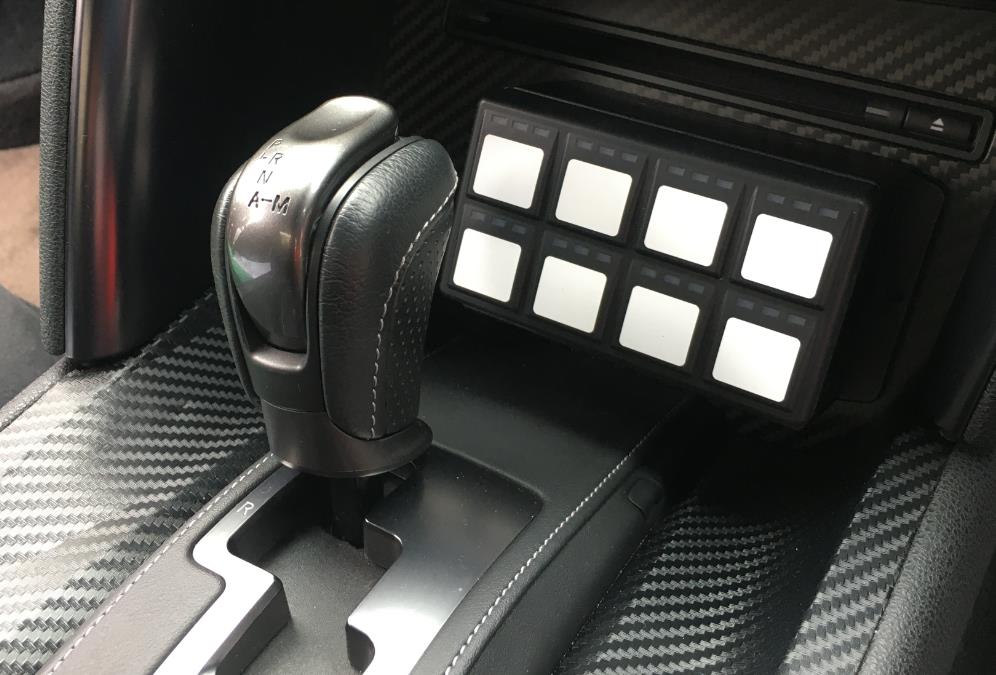
Figure 1.0 — Example of an Emtron 8 Button CAN Keypad fitment to a GTR R35.
The keypad is supplied blank and the (supplied) stickers are applied to indicate to the driver the purpose of each button once configured.
2.0 Specifications
All configuration is performed via the Emtune software:
- Keypad programming
- Device Backlight
- LED Indicator Brightness
- Individual button modes
- Individual button memories
- CAN broadcast of status
Communications
- Single CAN Bus
- Baud Rate 1 Mbps
LED Indicator Wavelength
- RED = 640nm
- AMBER = 601nm
- GREEN = 525nm
Power
- 8 to 22 Volts
- Current limit 0.2A
- Reverse Battery Protection
- Short Circuit Protection
Operating temperature
- -40°C to 85°C
Connection
- 1 x Deutsch DT4 Connector
2.1 Software Installation Procedure
- Connect Emtune to the ECU.
- Firmware Version 2.15.0 or later must be used.
- Select the CAN Bus the device is to be wired to: Config → Communications → CAN Bus X → CAN Bus X Channel X.
- Enable the channel.
- Select Data set 40 — Emtron 8-way Keypad.
2.2 Hardware Installation Procedure
The keypad should be mounted securely such that it is convenient for use by the driver. Mounting studs are M6 × 1.0mm (2 places).
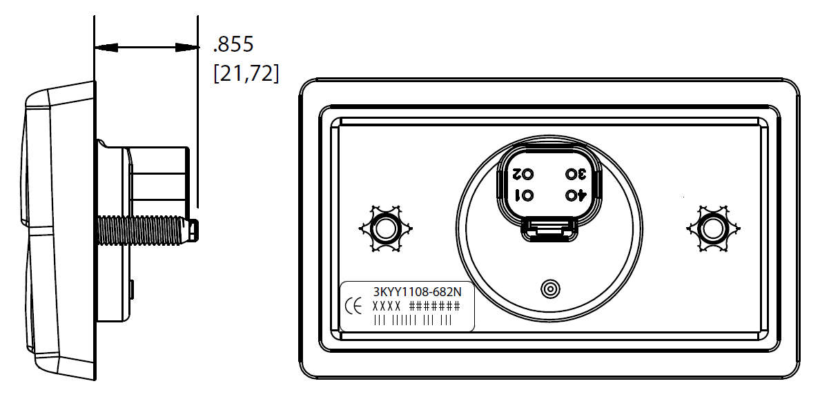
Figure 1.2 / 1.3 — Rear & side view of the keypad showing mounting stud positions and installed orientation with button numbers.
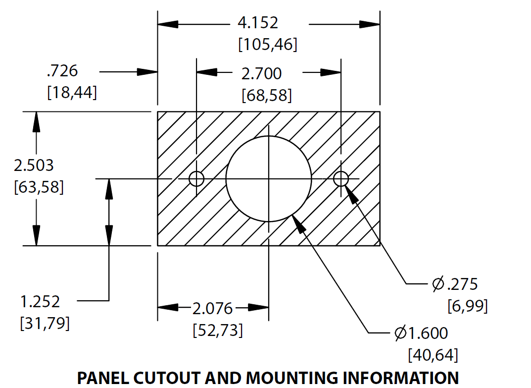
Figure 1.4 — Panel cut-out & mounting information to physically mount the keypad (not to scale).
2.3 Hardware Wiring
Power and CAN flying loom connection to the supplied DT4 connector. (Wire colours are recommended only.)
Table 1.0 — CAN Keypad Power and CAN Deutsch Connector Pinout
| Pin | Function | Wire Colour |
|---|---|---|
| 1 | 12V Supply | Red |
| 2 | Ground | Black |
| 3 | CAN Hi | Yellow |
| 4 | CAN Lo | Green |
2.4 CAN Bus Wiring
The 8 Button CAN Keypad does not include an on-board CAN terminating resistor, allowing the device to be wired at any position on the Bus. CAN termination must be done correctly by using a 120 ohm (0.25W) resistor at each end of the Bus system.
CAN bus wiring precautions
- CAN Bus High and Low are differential signals, so twisted pair MUST be used. Failing to do so will compromise the entire CAN Bus System.
- In some extreme environments, shielded twisted pair may be required to help with reliability and data integrity.
- The fewer connectors in any transmission system the better. Unnecessary connectors are almost guaranteed to present an impedance discontinuity and hence may cause reflections and data loss.
- CAN Bus termination must be done correctly using a 120 ohm 0.25W resistor at each END of the bus system.
- Maximum stub length to a device from the main Bus is recommended at 0.3m, in accordance with the High-Speed ISO 11898 Standard.
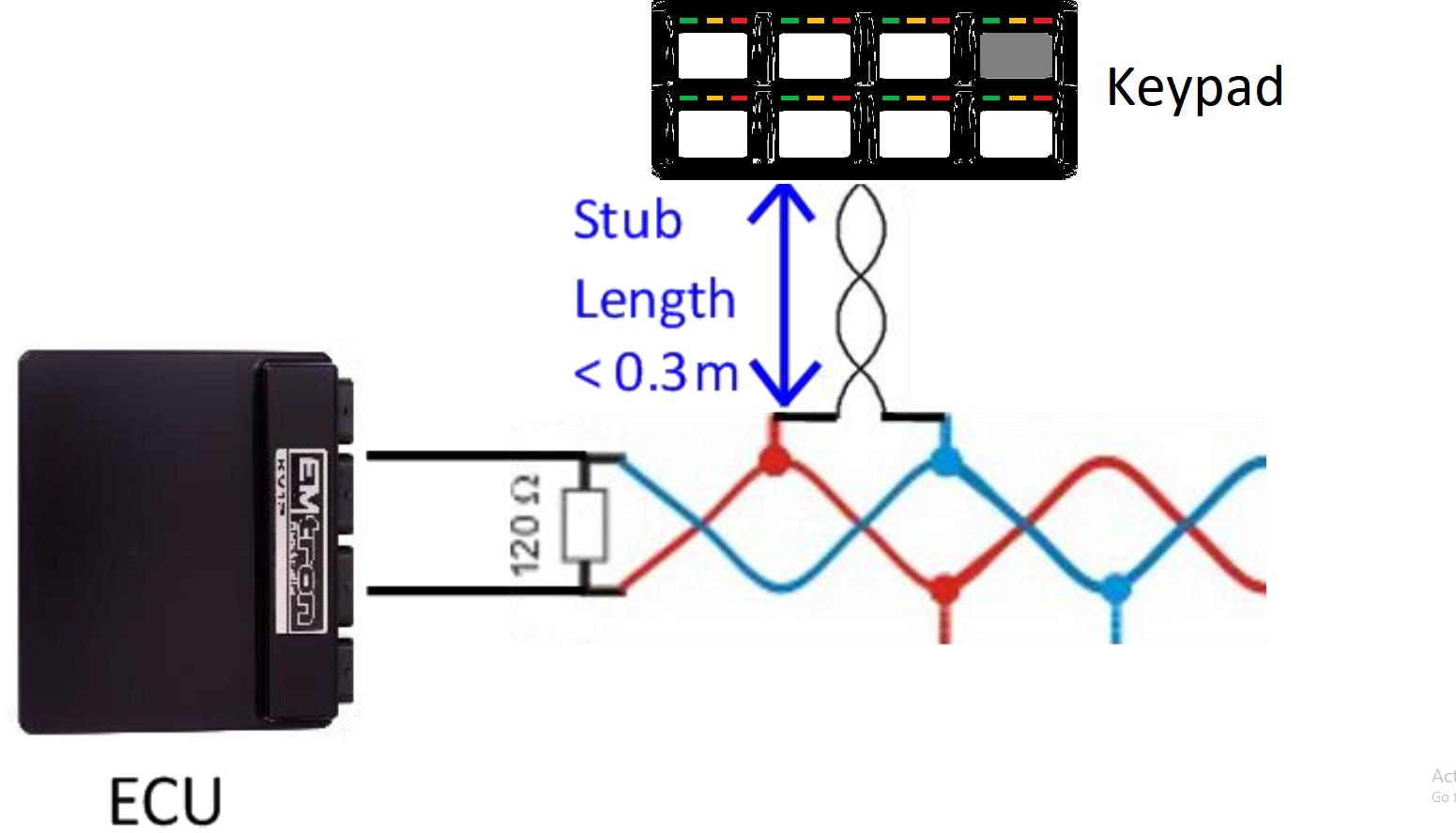
Figure 1.5 / 1.6 — CAN Bus wiring example with the ECU and CAN Keypad at each end (120 Ohm termination), and a stub length of less than 0.3m.
3.0 Configuration
The keypad programming is accessed via: Config → Communications → Emtron CAN Devices → Emtron Keypad.
Each switch button is individually defined, and the Backlight & LED Brightness are set. The memory function for each button can also be enabled if desired.
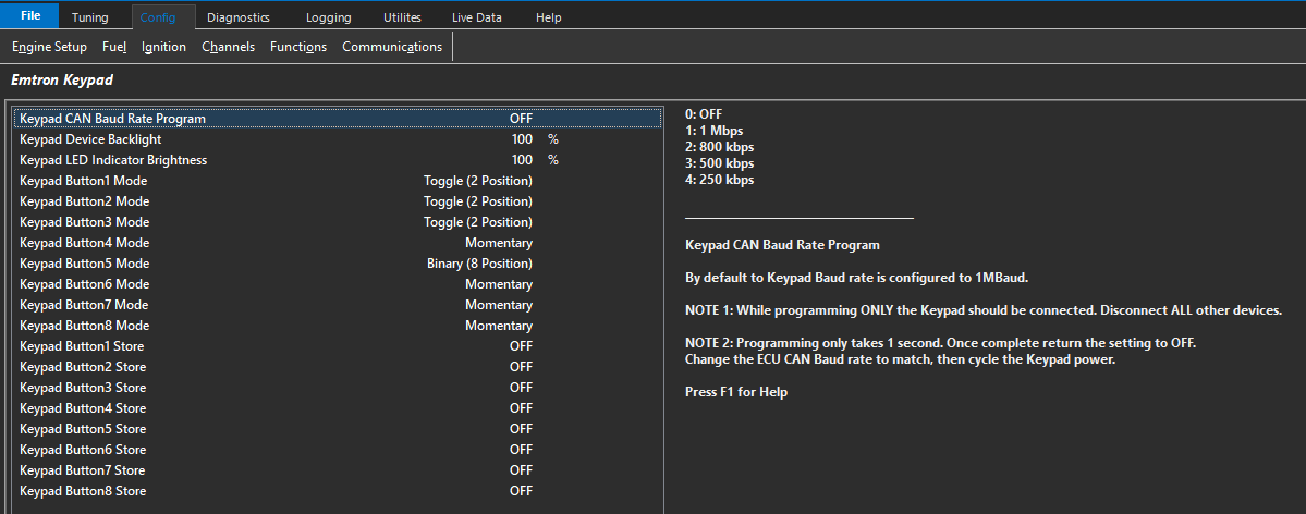
Figure 1.8 — Emtron Keypad programming page.
3.1 Input Switches
Various driver demand switches can be assigned to the CAN keypad. The switch can be assigned as a pre-defined input channel or used as a user-controlled runtime in a control strategy.
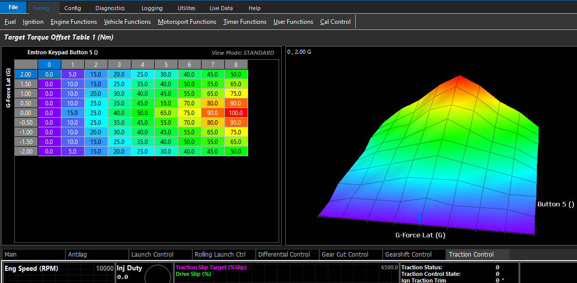
Figure 1.9 / 2.0 — Examples of switched inputs set to CAN keypad buttons, and a table runtime use of a CAN button.
The use of the keypad is only limited by the imagination of the user.