Emtron Thermocouple to CAN (ETC4 / ETC8M)
Kit Contents — When purchasing an ETC4 the following items are included:
- ETC4 Device with Flying Harness
- Deutsch DTM 4-way connector and female pins (DTM06-4S)
- Deutsch DTM 12-way connector and male pins (DTM04-12PA)
1.0 Description
The Emtron Thermocouple (EGT) to CAN devices are available in both Standard and Mil Spec versions.
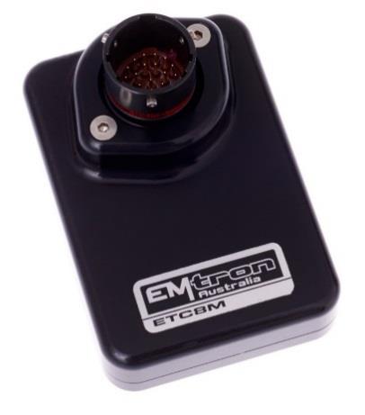
ETC8M — Mil Spec 8 channel Thermocouple to CAN device with Deutsch Autosport connector.
ETC8M — The ETC8M is a Mil Spec 8 Channel Thermocouple to CAN device using the Motorsport-proven Deutsch Autosport connector (Red). The enclosure is made from billet 6061 aluminium and is waterproof to allow for implementation in extreme environments.
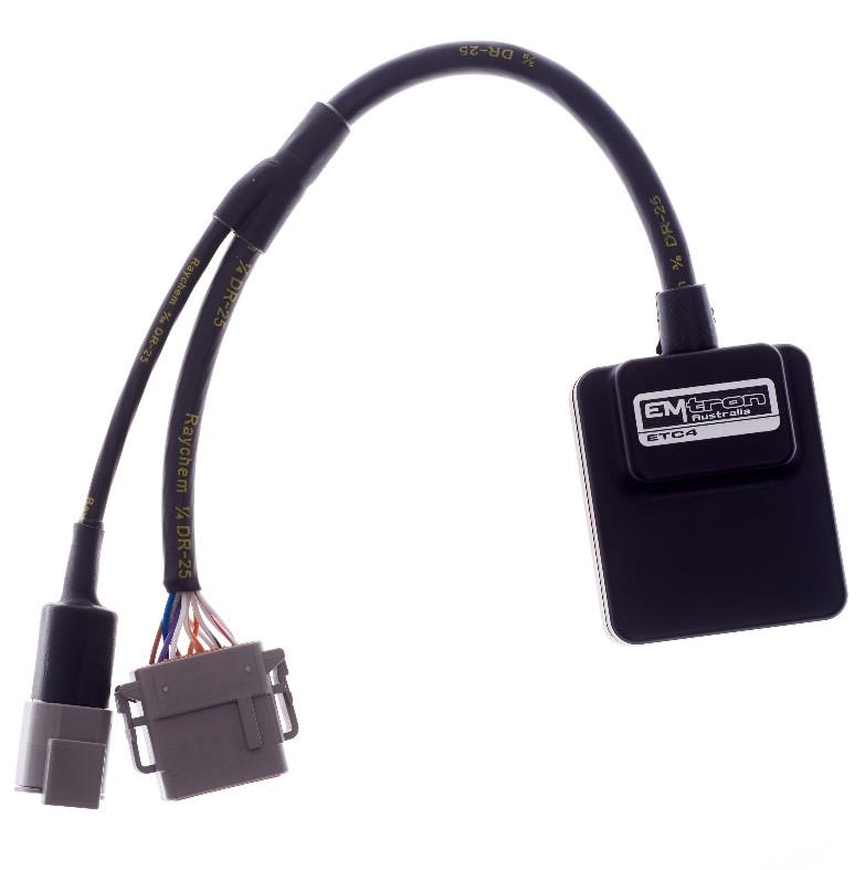
ETC4 — 4 channel Thermocouple to CAN device with Deutsch DTM connectors.
ETC4 — The ETC4 is a 4 channel Thermocouple to CAN device with a concentric twisted flying loom system, terminated with the reliable and environmentally sealed Deutsch DTM connector. The waterproof enclosure is extremely compact and made from billet 6061 aluminium.
Both devices accurately measure the exhaust gas temperature or cylinder head temperature using K-type thermocouples with a range of -50 to 1350 Degrees Celsius. The device is connected to the ECU via CAN bus and will be automatically detected, significantly minimising configuration time.
2.0 Specification
Power Supply
- Operating Voltage: 7.0 to 22.0 Volts DC
- Operating Current: 25mA (ETC4) and 30mA (ETC8M) at 14.0V
- Reverse Battery Protection: 0mA current draw
- Battery Transient/Over Current Protection
Internal
- 64MHz 16-bit Automotive Processor
- Instrumentation Amplifier for K-Type voltage measurement with precise gain control and protected inputs
- Built-in cold junction compensation
- Thermocouple open circuit fault detection
Inputs - General
- K-Type Thermocouple Inputs — Range: -50 to 1350°C, Resolution 1°C
- Sampling rate 500 Hz — Resolution: 1.22mV (12 Bit)
- Internal or External Cold Junction Correction — Range: -50 to 150°C, Resolution 1°C
- ETC8M: 8× K-Type Thermocouple Inputs, 1× External Cold Junction Input
- ETC4: 4× K-Type Thermocouple Inputs, 1× External Cold Junction Input
Communications
- CAN 2.0B Baud Rate: 250kBaud, 500kBaud or 1Mbaud Auto Detect
- CAN Transmit Rate Adjustable: 50Hz / 100Hz / 200Hz / 500Hz
Operating Temperature: -30 to 100°C (-22 to 212°F)
Physical
- ETC8M: Enclosure Size 52 × 74 × 18 mm, 125g
- ETC4: Enclosure Size 63 × 54 × 20 mm, 160g
3.0 Installation
Each device has an M4 × 1.5 thread tapped into the base of the enclosure and can be used for mounting. In high vibration applications rubber mounting is recommended.
WarningCAUTION When mounting the device inside the engine compartment, it should be positioned in cooler areas and away from heat sources such as exhaust manifolds. Any unnecessary radiated heat may affect device performance.
3.1 ETC4 Pinout
Table 3.0 — ETC4 Power and CAN Deutsch Connector (DTM 4 pin, M)
| Pin | Function | Wire Colour |
|---|---|---|
| 1 | Ground | BLACK |
| 2 | CAN Lo | GREEN |
| 3 | CAN Hi | YELLOW |
| 4 | 12V Supply | RED |
Table 3.1 — ETC4 Thermocouple Flying Loom Connector (DTM 12 pin, F — DTM06-12SA)
| Pin | Function | Wire Colour |
|---|---|---|
| 1 | EGT 1+ | BRN |
| 2 | EGT 2+ | BLUE |
| 3 | EGT 3+ | GREY |
| 4 | EGT 4+ | W/GREY |
| 5 | NC | W/BLUE |
| 6 | External Cold Junction | W/BRN |
| 7 | Analog Sensor 0V Reference | W/RED |
| 8 | NC | W/BLACK |
| 9 | EGT 4- | W/OR |
| 10 | EGT 3- | OR |
| 11 | EGT 2- | WHITE |
| 12 | EGT 1- | PUR |
3.2 ETC8M Pinout
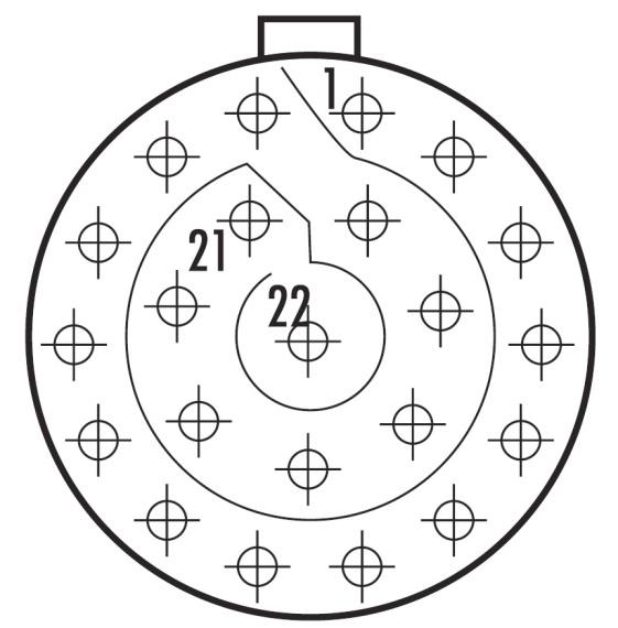
ETC8M Deutsch Autosport AS Series connector. Mating connector loom side: AS612-35SN (Red).
Table 3.2 — ETC8M Pinout
| Pin | Function | Pin | Function |
|---|---|---|---|
| 1 | 14 V Supply | 12 | EGT 4+ |
| 2 | Ground | 13 | EGT 5- |
| 3 | CAN Hi | 14 | EGT 5+ |
| 4 | CAN Lo | 15 | EGT 6- |
| 5 | EGT 1- | 16 | EGT 6+ |
| 6 | EGT 1+ | 17 | EGT 7- |
| 7 | EGT 2- | 18 | EGT 7+ |
| 8 | EGT 2+ | 19 | EGT 8- |
| 9 | EGT 3- | 20 | EGT 8+ |
| 10 | EGT 3+ | 21 | Cold Junction Input (External) |
| 11 | EGT 4- | 22 | 0V Analog Sensor Reference |
3.3 CAN Bus
The ETC4 or ETC8M can be connected to the ECU’s CAN Bus 1 or 2. All devices on the CAN Bus must be configured to use the same baud rate. For this reason, all Emtron CAN devices will auto-scan the CAN bus until a successful baud rate has been detected. Once detected this rate will be stored and used at the next power up. The device will scan 3 different baud rates at 500ms intervals moving from 1Mbaud → 500kBaud → 250kBaud → 1Mbaud and so on.
NoteNOTE For this process to function effectively, when new devices are introduced to the CAN bus, they should initially be connected one at a time. This allows each device to sync up to the CAN Bus baud rate and store that setting. This typically takes 3-5 seconds.
The ETC4 and ETC8M leave the factory programmed with individual serial numbers, but all have the same Base CAN Address ID used to transmit data over the Bus. The CAN Base address can be adjusted from the factory setting using the ID Reprogramming Tool. This is required when 2 or more of the same devices are connected to the CAN Bus (see section 4.2).
- ETC4: Factory CAN Base Address of 691 only. Up to 3× ETC4 devices can be used on the CAN Bus giving a total of 12 available EGT Input Channels.
- ETC8M: Factory CAN Base Address of 700. Transmits data sequentially on the next ID (total CAN ID Range 700–701). Up to 2× ETC8M devices can be used on the CAN Bus giving a total of 16 available EGT Input Channels.
3.4 Thermocouple Polarity
The polarity of the thermocouple is critical and must be connected to the correct input. In most applications the red cable is the negative (–) and the yellow is the positive (+). Some sensors may also have a blue or black as the positive, which is counter-intuitive to conventional wiring methods.
3.5 Cold Junction Compensation
Both the ETC8M and ETC4 offer 2 options for Cold Junction compensation: Built-in and External Input.
Built-in Compensation (Default) — The device has an internal temperature sensor that measures the temperature of the connector so cold junction temperature compensation can be applied. This is the default mode used when the external input is not connected. With this setup, the thermocouple wire should be connected directly to the device. If the wires must be extended, then matching thermocouple wire should be used.
External Input — The input is pre-calibrated to use a standard Bosch NTC 2k5 Ohm at 20°C calibration with a 1K Ohm pullup resistor and temperature range of -30°C to 150°C. When the external input is connected to a sensor, the measured temperature is used for Cold Junction correction. For the ETC8M, connect the sensor to pins 21 and 22. For the ETC4, connect the sensor to pins 11 and 12 of the 12-way DTM connector.
3.6 Noise Immunity
To minimise signal contamination and maximise noise immunity, the CAN High and CAN Low wire pair must be twisted. It is recommended to twist the wire pairs at a minimum of one twist per 40mm of cable. This is very important and should always be implemented.
3.7 CAN Bus Wiring
- CAN Bus High and Low are differential signals, so twisted pair MUST be used.
- In some extreme environments, shielded twisted pair may be required to help with reliability and data integrity.
- The fewer connectors in any transmission system the better.
- CAN Bus termination must be done correctly by using a 120 ohm 0.25W resistor at each END of the bus system.
- Maximum stub length to a device from the main Bus is recommended at 0.3m, in accordance with the High-Speed ISO 11898 Standard.
The ETC8M or ETC4 devices do not include an on-board CAN termination resistor, allowing the device to be wired at any position on the Bus.
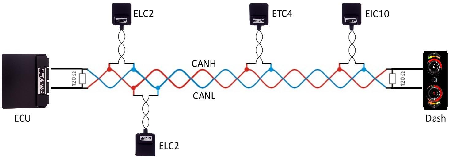
Figure 3.1 — CAN Bus wiring example: ECU and a device at each end with 120 Ohm termination.
4.0 ETC Device Configuration
Once the ETC4 or ETC8M is powered and connected to the ECU’s CAN bus, the following steps should be taken to complete the setup. All setup and device monitoring is done using Emtune, so this software needs to be installed and connected to the ECU.
NoteNOTE When a Thermocouple Input has been detected as Open Circuit, the Fault Value of -50.0°C will be transmitted over the CAN Bus.
4.1 ETC Single Device Setup
This involves 3 steps: Device Detection by the ECU, ECU CAN Bus configuration, and ETC Live Data Monitoring.
4.11 ETC Device Detection — To confirm the ETC device has been detected, connect to the ECU using Emtune. Open the ECU Runtime menu (F3) and select the Communications Tab. This lists the CAN Device Model, Device Serial Number, Device Firmware Version, Device Hardware Version, and CAN Base Address ID for each detected Emtron CAN device. At this stage the ECU has only detected the device — it has not yet been configured to an ECU CAN Channel. Note the CAN Base Address ID (factory setting is 691 for the ETC4, 700 for the ETC8M).
4.12 ECU CAN Configuration for Single Device — Configure an ECU CAN channel to allow the ECU to decode the ETC CAN packets (e.g. CAN 1 – Channel 3):
- Set “Enable” to 1 (ON).
- Set “CAN Base Address” to the Base Address shown in the runtime (691 for ETC4, 700 for ETC8M).
- Set “DATA Set” to 60 (ETC4 1× Device) or 65 (ETC8M 1× Device).
4.13 ETC Data Monitoring for Single Device — To confirm the ETC data is being decoded by the ECU, open the runtime menu (F3) → Emtron CAN Device Tab. The ETC4/ETC8M EGT and Cold Junction Temperatures live data can be viewed.
4.2 ETC Multiple Device Setup
The Base CAN Address ID used to transmit data over the Bus is the same for each device type by default. When multiple ETC4/ETC8M devices are installed on the same CAN Bus, each device MUST have a unique CAN Base Address to avoid Bus conflicts. The CAN Base Address ID is reprogrammed using the ID Reprogramming Tool (section 4.22).
NoteREMEMBER When multiple new devices are introduced to the CAN bus, they should initially be connected one at a time so each device can sync to the CAN Bus baud rate and store that setting (3-5 seconds).
4.21 Multiple Device Detection — With multiple devices connected, the CAN Summary List (F3 → Communications Tab) shows each device. By default all share the same Base Address (691 for ETC4). To avoid Bus conflicts, when re-programming the Base Address for each device the IDs MUST be: (1) sequential in order, (2) have a gap of 1 number between each ETC4 device, (3) have a gap of 2 numbers between each ETC8M device. Recommended:
- ETC4 Device 1/2/3: ID Base Address 691 / 692 / 693
- ETC8M Device 1/2: ID Base Address 700 (range 700–701) / 702 (range 702–703)
4.22 CAN Base Address ID Reprogramming — In Emtune go to Config View → Communications → Emtron CAN Devices → Emtron CAN Device Programming. Enter the device Serial Number and the Custom Address, tick “Program Address”, then select “Program”. Repeat for each device. Confirm via F3 → Communications Tab that each device now has a unique Base Address ID.
4.23 ECU CAN Configuration for Multiple Devices — Only 1 CAN Channel is required for multiple devices (e.g. CAN 1 – Channel 3):
- Set “Enable” to 1 (ON).
- Set “CAN Base Address” to the lowest Base Address ID (e.g. 691).
- Set “DATA Set” to 62 (Emtron ETC4 3× Devices, CAN PID 691/692/693). Use option 61 for 2× ETC4 devices.
You only need to program in the lowest Base Address — the ECU automatically configures the remaining IDs based on the assumption the IDs are sequential.
4.24 Data Monitoring for Multiple Devices — Confirm via the runtime menu (F3) → Emtron CAN Device Tab.
5.0 ECU Channel Configuration
Once the ECU has been configured to receive the ETC data, the next step is assigning the data to ECU channel(s). Select Config View → Channels → Inputs Setup → EGT Tab. Select “Exhaust Gas Temp Cyl 1” and open the Input Setup menu:
- Set Input Source = CAN ETC4 #1 Ch-1
- Filter = 0 (normally not required as filtering is done by the ETC device)
- Calibration Type = Predefined
- Predefined Calibration = CAN – EGT 1:1 Scaling, or ETC8M/ETC4 1:1 Scaling
NoteNOTE The CAN values can be scaled using the 2D calibration if required by setting the Calibration Type to “Custom”. Repeat the process for the remaining channels.
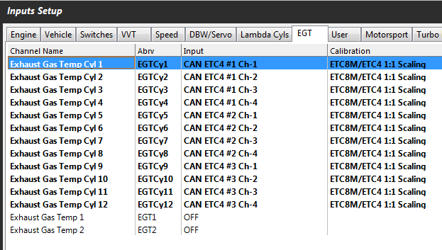
Figure 5.1 — ECU EGT input channels assigned to ETC4 CAN data.
6.0 ETC Custom Device Setting
The EGT data Transmit rate is adjustable on the ETC4 and ETC8M: 200Hz (Default), 50Hz, 100Hz, 500Hz. Configure using Emtune from Config View → Communications → CAN Device → Emtron Thermocouple to CAN Setup. Adjust to suit the application and available CAN bandwidth.
NoteNOTE Once changed, the setting is automatically stored by the ETC device and used on the next power cycle.
7.0 Ordering Information
| Product | Part Number |
|---|---|
| Emtron ETC4 | 5203-4 |
| Emtron ETC8M | 5203-813 |
Appendix 1 — CAN Bus Data Packaging (Device FW 36 or Later)
This section provides detailed information on the CAN ID data structure and requires an understanding of both CAN protocols and data packaging. If the device is connected to an Emtron ECU, the CAN Bus packet is automatically decoded when the correct CAN Dataset is selected and no additional setup is required.
ETC4 CAN Data Format — ID 691 / 0x2B3 (Default), Standard 11-bit identifier, Transmit from Device, Length 7 bytes, Tx Rate adjustable (50/100/200/500 Hz).
| Name | Start bit | Length (bits) | Byte Order | Data Type | Multiplier | Offset | Units | Example |
|---|---|---|---|---|---|---|---|---|
| EGT Channel 1 | 0 | 12 | Big Endian | Unsigned | 1 | -50 | DegC | CAN 900 = 850 DegC |
| EGT Channel 2 | 12 | 12 | Big Endian | Unsigned | 1 | -50 | DegC | |
| EGT Channel 3 | 24 | 12 | Big Endian | Unsigned | 1 | -50 | DegC | |
| EGT Channel 4 | 36 | 12 | Big Endian | Unsigned | 1 | -50 | DegC | |
| Cold Junc. Temp | 48 | 8 | NA | Unsigned | 1 | -50 | DegC | CAN 68 = 18 DegC |
ETC8M CAN Data Format — ID 700 / 0x2BC (channels 1-4 + cold junction) and ID 701 / 0x2BD (channels 5-8 + open-circuit status), Standard 11-bit identifier, Transmit from Device, Length 7 bytes.
ID 700 carries EGT Channels 1-4 (start bits 0/12/24/36, 12 bits each, Big Endian, ×1, offset -50, DegC) plus Cold Junc. Temp (start bit 48, 8 bits, ×1, offset -50).
ID 701 carries EGT Channels 5-8 (start bits 0/12/24/36, 12 bits each, Big Endian, ×1, offset -50, DegC) plus an Open-Circuit Status byte (start bit 48, 8 bits):
| Bit | Meaning | Bit | Meaning |
|---|---|---|---|
| 0 | EGT Ch 1 Open Cct | 4 | EGT Ch 5 Open Cct |
| 1 | EGT Ch 2 Open Cct | 5 | EGT Ch 6 Open Cct |
| 2 | EGT Ch 3 Open Cct | 6 | EGT Ch 7 Open Cct |
| 3 | EGT Ch 4 Open Cct | 7 | EGT Ch 8 Open Cct |
Appendix 2 — CAN Bus Data Packaging (Device FW 35 or earlier)
The packet structure is identical to Appendix 1, except that EGT Channels 1 and 3 use Little Endian byte order (Channels 2 and 4 remain Big Endian). This applies to both the ETC4 (ID 691) and ETC8M (IDs 700 and 701). All multipliers, offsets (-50), units (DegC) and the Open-Circuit Status bit mapping are unchanged.