Subsections of Accessories
Emtron 8 Button CAN Keypad
1.0 Description
The Emtron 8 Button CAN Keypad provides a programmable switching solution which is available for all Emtron ECUs. The use of the CAN Keypad allows unique application-specific user controls to be included in the ECU control strategy. The buttons can be used for a variety of inputs from simple switching to binary selectable runtimes. Three LED lights are located above each button which are used to indicate the current state of the unit.
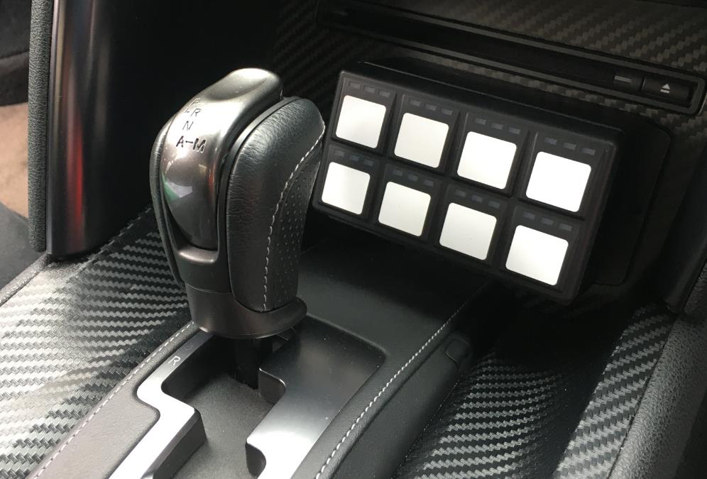
Figure 1.0 — Example of an Emtron 8 Button CAN Keypad fitment to a GTR R35.
The keypad is supplied blank and the (supplied) stickers are applied to indicate to the driver the purpose of each button once configured.
2.0 Specifications
All configuration is performed via the Emtune software:
- Keypad programming
- Device Backlight
- LED Indicator Brightness
- Individual button modes
- Individual button memories
- CAN broadcast of status
Communications
- Single CAN Bus
- Baud Rate 1 Mbps
LED Indicator Wavelength
- RED = 640nm
- AMBER = 601nm
- GREEN = 525nm
Power
- 8 to 22 Volts
- Current limit 0.2A
- Reverse Battery Protection
- Short Circuit Protection
Operating temperature
- -40°C to 85°C
Connection
- 1 x Deutsch DT4 Connector
2.1 Software Installation Procedure
- Connect Emtune to the ECU.
- Firmware Version 2.15.0 or later must be used.
- Select the CAN Bus the device is to be wired to: Config → Communications → CAN Bus X → CAN Bus X Channel X.
- Enable the channel.
- Select Data set 40 — Emtron 8-way Keypad.
2.2 Hardware Installation Procedure
The keypad should be mounted securely such that it is convenient for use by the driver. Mounting studs are M6 × 1.0mm (2 places).
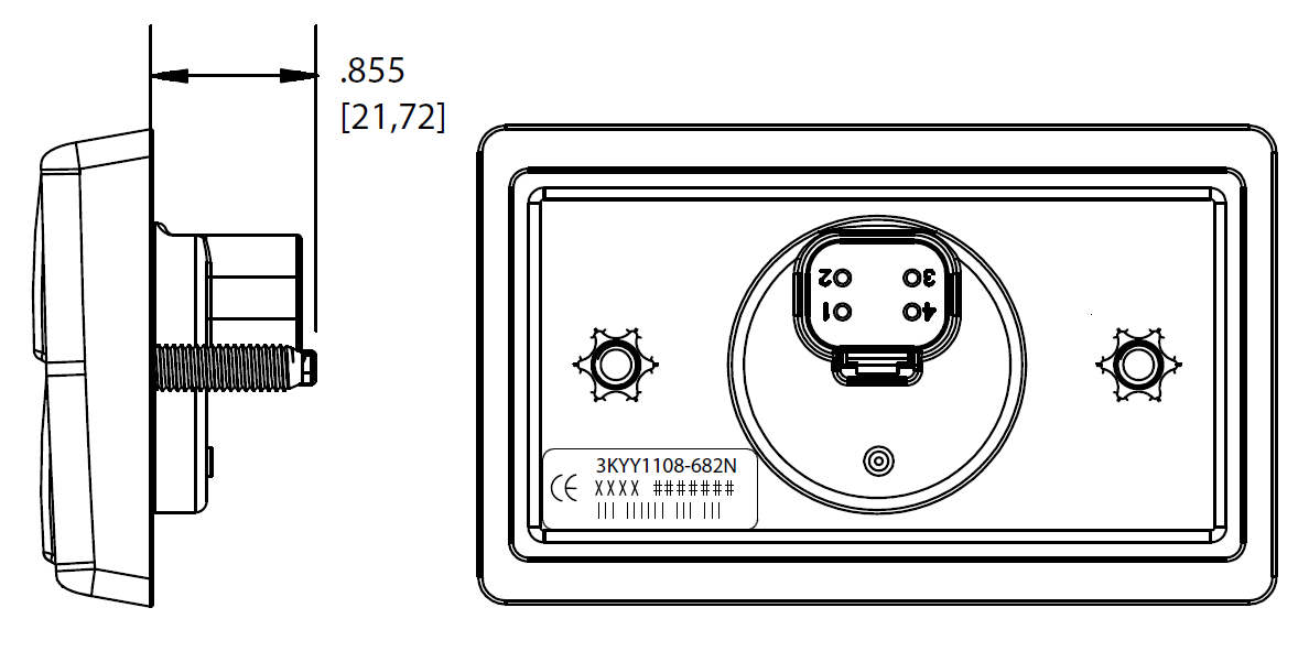
Figure 1.2 / 1.3 — Rear & side view of the keypad showing mounting stud positions and installed orientation with button numbers.
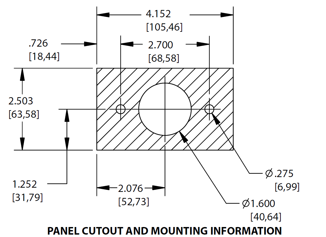
Figure 1.4 — Panel cut-out & mounting information to physically mount the keypad (not to scale).
2.3 Hardware Wiring
Power and CAN flying loom connection to the supplied DT4 connector. (Wire colours are recommended only.)
Table 1.0 — CAN Keypad Power and CAN Deutsch Connector Pinout
| Pin | Function | Wire Colour |
|---|---|---|
| 1 | 12V Supply | Red |
| 2 | Ground | Black |
| 3 | CAN Hi | Yellow |
| 4 | CAN Lo | Green |
2.4 CAN Bus Wiring
The 8 Button CAN Keypad does not include an on-board CAN terminating resistor, allowing the device to be wired at any position on the Bus. CAN termination must be done correctly by using a 120 ohm (0.25W) resistor at each end of the Bus system.
CAN bus wiring precautions
- CAN Bus High and Low are differential signals, so twisted pair MUST be used. Failing to do so will compromise the entire CAN Bus System.
- In some extreme environments, shielded twisted pair may be required to help with reliability and data integrity.
- The fewer connectors in any transmission system the better. Unnecessary connectors are almost guaranteed to present an impedance discontinuity and hence may cause reflections and data loss.
- CAN Bus termination must be done correctly using a 120 ohm 0.25W resistor at each END of the bus system.
- Maximum stub length to a device from the main Bus is recommended at 0.3m, in accordance with the High-Speed ISO 11898 Standard.
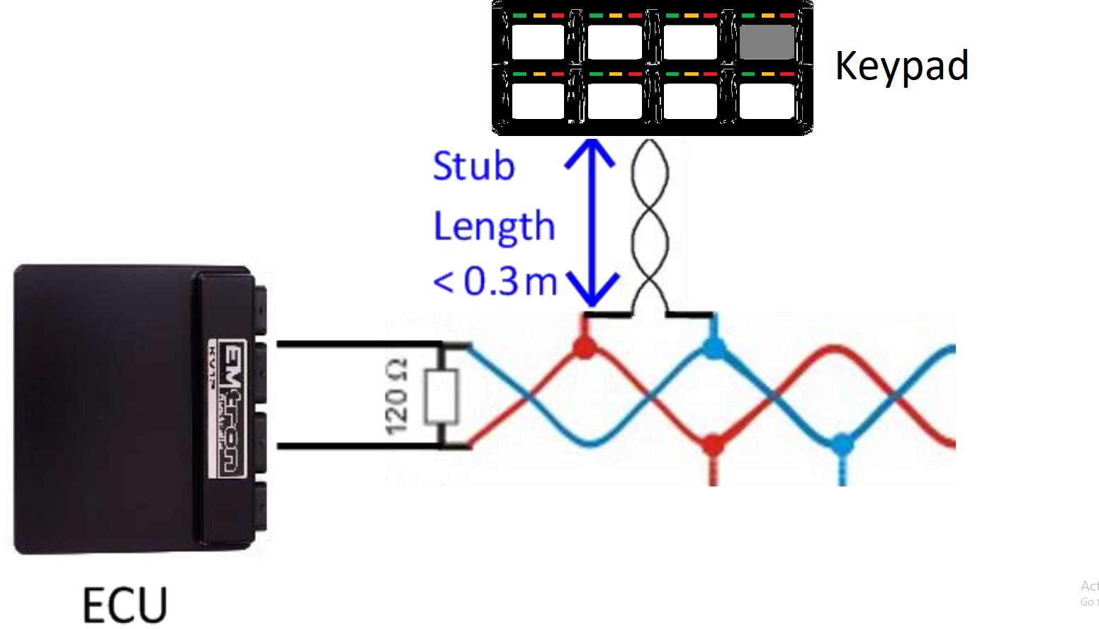
Figure 1.5 / 1.6 — CAN Bus wiring example with the ECU and CAN Keypad at each end (120 Ohm termination), and a stub length of less than 0.3m.
3.0 Configuration
The keypad programming is accessed via: Config → Communications → Emtron CAN Devices → Emtron Keypad.
Each switch button is individually defined, and the Backlight & LED Brightness are set. The memory function for each button can also be enabled if desired.
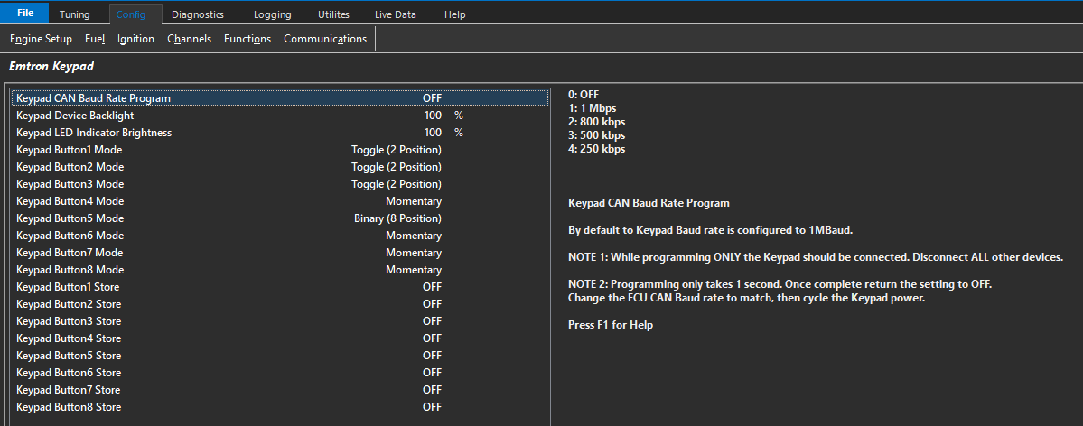
Figure 1.8 — Emtron Keypad programming page.
3.1 Input Switches
Various driver demand switches can be assigned to the CAN keypad. The switch can be assigned as a pre-defined input channel or used as a user-controlled runtime in a control strategy.
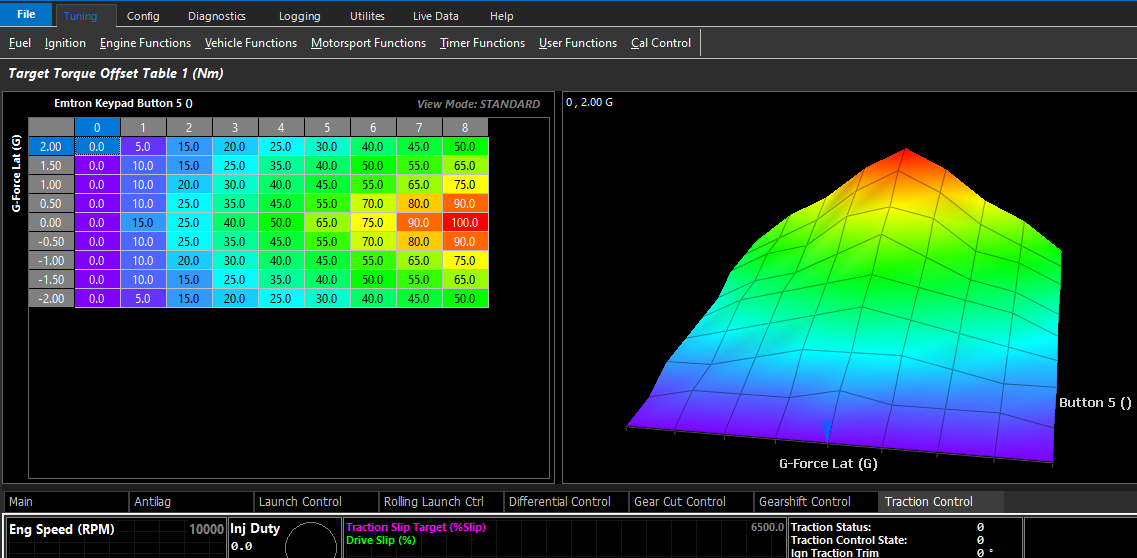
Figure 1.9 / 2.0 — Examples of switched inputs set to CAN keypad buttons, and a table runtime use of a CAN button.
The use of the keypad is only limited by the imagination of the user.
Emtron CAN Gauge
Kit Contents — When purchasing the Emtron CAN Gauge the following items are included:
- 1 × Emtron CAN Gauge
- 1 × Mounting Bracket
- 2 × Mounting Bracket thumbscrews
- 1 × Unterminated standard flying loom
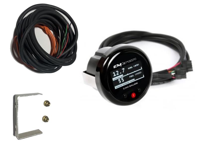
Emtron CAN Gauge kit contents.
1.0 Description
The Emtron CAN Gauge by Gauge ART is a compact 52mm OLED gauge that connects to all Emtron ECUs to display real-time data from CAN broadcasts. It is also compatible with aftermarket and factory ECUs.
The gauge is wirelessly configurable using an Android or Apple iOS mobile device through Wi-Fi. Gauge channels, bar graphs, warning points, and custom gauge labels can be configured using the “Gauge ART CAN Gauge App”.
2.0 Specification
- 52mm display
- Configurable low and high warnings
- Day / Night dimming
- Wireless Wi-Fi configuration
- Connect more than one unit
- Runtime channel names user definable
- User defined channels can be displayed
- OLED Display
- 1, 2 or 4 channel gauge layouts available
- Up to 10 different pages available
Inputs: 1 × CAN bus
Operating Temperature: -30 to 85°C (-22 to 185°F)
3.0 Requirements
3.1 Compatible ECU
All Emtron ECUs are compatible. Most common ECUs are also compatible, including: Adaptronic, AEM EMS 4, AEM EMS Series 2, AEM Infinity, Factory CAN OEM (requires OBD Link), Hondata KPro4 / S300, Link G4+, MaxxECU, Megasquirt MS3, Motec M1 Series, ProEFI, Syvecs S6/S6+/S8, Vipec, Wolf EMS.
3.2 Smartphone or Tablet
Smartphone or tablet with Apple iOS or Android v4.4 or later.
3.3 ECU Terminals, Connector, & Installation tools
The Emtron CAN Gauge includes an unterminated flying loom that will require connection to a power source and the ECU CAN bus.
4.0 Wiring
4.1 CAN Gauge Wiring
Table 4.1 — CAN Gauge Wiring
| Wire | Function |
|---|---|
| Red | 14 V Supply |
| Black | Ground |
| Orange | 14 V Illumination |
| White | CAN Hi |
| Green | CAN Lo |
4.2 CAN Bus Wiring
The CAN Gauge includes a user-configurable 120 ohm terminating resistor jumper. The resistor is enabled when the jumper is in place.
CAN bus wiring precautions
- CAN Bus High and Low are differential signals, so twisted pair MUST be used. Failing to do so will compromise the entire CAN Bus System.
- In some extreme environments, shielded twisted pair may be required to help with reliability and data integrity.
- The fewer connectors in any transmission system the better. Unnecessary connectors are almost guaranteed to present an impedance discontinuity and hence may cause reflections and data loss.
- CAN Bus termination must be done correctly by using a 120 ohm 0.25W resistor at each END of the bus system.
- Maximum stub length to a device from the main Bus is recommended at 0.3m, in accordance with the High-Speed ISO 11898 Standard.
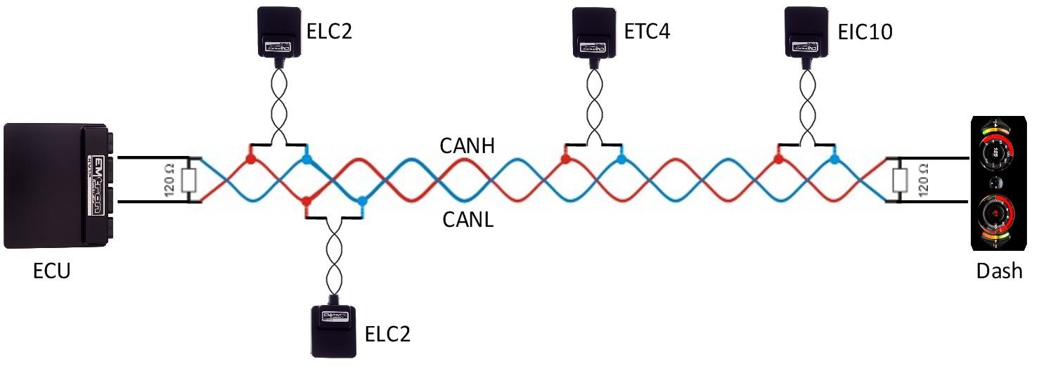
Figure 4.1 — CAN Bus wiring example: ECU and Dash at each end with 120 Ohm termination.
4.3 Illumination Signal Wiring
The CAN Gauge can dim illumination at night when the parking lights are on. Using the factory service manual, find a wire in the interior that switches to +12V power when the parking lights are on. Verify with a voltmeter or test light that the wire receives +12V when the parking lights are turned on. Note that many vehicles have an illumination-switched connector in the interior fuse box.
5.0 Gauge ART Application
Search “gaugeART” and download the gaugeART CAN Gauge App from your device’s app store. If you have two gauges, remove one of the gauges from power — program one gauge at a time.
Turn on your ignition to turn on the CAN Gauge; the welcome screen will be shown. Connect to the gauge via Wi-Fi by tapping Settings → Wi-Fi. Tap on gaugeART and enter the default password 12345678. Allow the gauge to connect. If prompted with a message that internet is not available with this device, tap OK. You may now open the gaugeART CAN Gauge App.
5.1 Create Configuration
Tap Create Configuration. Select ECU type and tap Next. The gaugeART CAN Gauge allows you to create up to 10 pages of gauge layouts in 1, 2, or 4 gauge layouts. Tap the centre of the screen for Gauge Screen Setup. On this screen, select a channel, configure graph range, update speed, warnings, and gauge labels (e.g. rename “MAP” to “BOOST”). Tap Previous Page to return. Tap the left side to change the configuration between 1, 2, or 4 gauge layout. Tap Next Page to add a new page or Delete to remove a page.
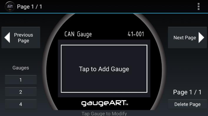
Figure 5.1 — gaugeART CAN Gauge App configuration.
5.2 Save & Send Configuration
Tap the icon in the top right and tap Save. Enter a name under “Enter Save File Name” and tap Save. To program, tap Send Configuration. The gauge will be programmed and will show your configuration. Programming takes anywhere from 10–60 seconds and will update the gauge’s firmware automatically if an update is available.
5.3 Load Configuration
Select “Emtron”. Previously saved files will be shown in the second drop-down. Click Load to open the file. To edit your saved configuration, tap Edit once loaded. To program, tap Send Configuration.
6.0 Emtune Settings
Ensure the ECU firmware Version is 2.17.0. If using earlier firmware versions, the display may still be operational; however, some functionality and channels will not be available.
Make sure the ECU is powered up and is Online in Emtune. Go to Config View → Communications → CAN Bus 1 → CAN Bus 1 Setup → CAN 1 Baud Rate and set to 1Mbps.
Open the first available Channel. If there is nothing else already configured on the CAN bus, then CAN 1 Channel 1 would be the first available channel. If this channel is already used, simply select a channel that is free — the CAN 1 channel number selection has no effect on the operation.
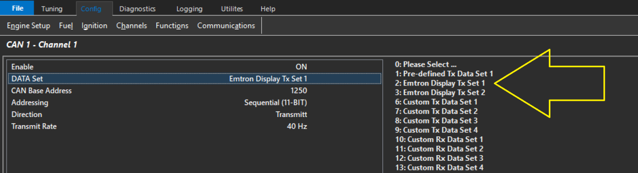
Figure 6.2 — CAN 1 Channel 1 setup menu.
Store setting changes permanently in the ECU by pressing F4. Switch power OFF and ON to the ECU to ensure the updated CAN bus settings have been initialised. The CAN Gauge should now be receiving and displaying live runtimes.
7.0 Ordering Information
| Product | Part Number |
|---|---|
| Emtron CAN Gauge | 537-711 |
Emtron Input Expansion to CAN
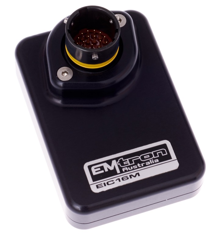
When purchasing an EIC16M the loom side mating Autosport connector is not included but can be purchased separately.
1.0 Description
The EIC16M is a Mil Spec device designed to increase the Input channel capability of all Emtron ECUs with 16 high resolution analog and/or 4 frequency based inputs. The device is connected via CAN bus and will be automatically detected which will significantly minimalize configuration time. The enclosure is made from billet 6061 aluminium and is waterproof, allowing for use in extreme environments. Installation is made simple through use of a Motorsport proven Deutsch Autosport connector system.
2.0 Specification
Power Supply
- Operating Voltage: 7.0 to 22.0 Volts DC
- Operating Current: 30mA at 14.0V
- Reverse Battery Protection with zero current draw
- Battery Transient/Over Current Protection
Internal
- 64MHz 16-bit Automotive Processor
- Analog Channel Sampling Rate 1000 Hz
Inputs - General
- Analog Inputs
- Range 0.0V to 5.0V, Resolution. 1.22mV 12 Bit
- 1st order 1600Hz low pass filter
- Analog sampling rate of 1000Hz
- Frequency Inputs
- Range 0.5Hz up to 6500.0Hz, Resolution. 0.1Hz
- Magnetic and Hall effect sensor compatible
- Rising Edge Threshold = 1.65V, Falling Edge Threshold = 1.0V
EIC16M – 16 Analog Inputs
- ANV1-12: Analog Inputs 0.0V - 5.00V range.
- Switchable 1k pull-up resistor on ANV9-12 to the 5V Sensor Supply for temperature measurement.
- Input Impedance 100k to ground
- ANV13-16 / Frequency Input 1-4
- Analog Inputs 0.0 – 16.0V Range. Resolution. 3.90mV 12 Bit, suitable for analog inputs and switched inputs.
- Switchable 1k Pullups with blocking diode to 8V Supply
- Input Impedance 50k to ground
- Frequency Range 0.5Hz up to 6500.0Hz, Resolution. 0.1Hz
Outputs
- 5V Sensor Supply. Output current 250mA. Short circuit to ground protected.
Communications
- CAN 2.0B Baud Rate: 250kBaud, 500kBaud or 1Mbaud Auto Detect
- CAN Transmit Rate Adjustable: 50Hz/100Hz/200Hz/500/1000 Hz
Operating Temperature
- Operating Temperature Range: -30 to 100°C (-22 to 212°F)
Physical
EIC16M
- Enclosure Size 52 mm x 74 mm x 18 mm
- 125g
3.0 Installation
Each device has a M4 x 1.5 thread tapped into the base of the enclosure and can be used for mounting. In high vibration applications rubber mounting is recommended.
CAUTION: When mounting the device inside the engine compartment, it should be positioned in cooler areas and away from heat sources such as exhaust manifolds. Any unnecessary radiated heat may affect device performance.
3.1 EIC16M Pinout
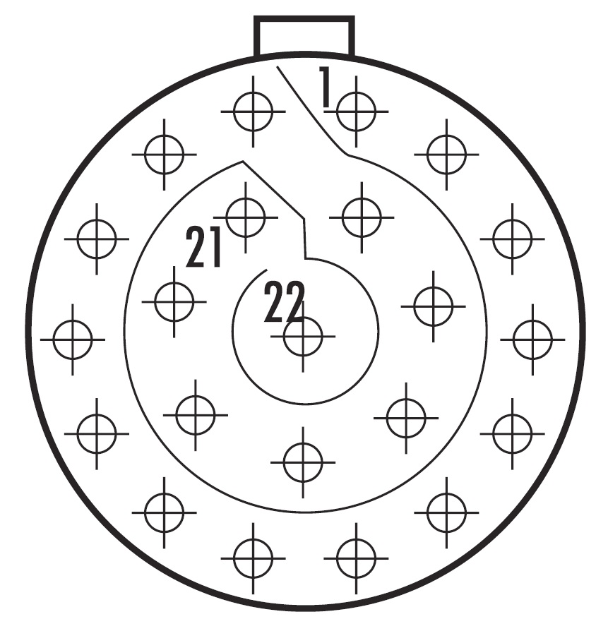
| Mating Connector Loom Side (Deutsch Autosport AS Series) |
|---|
| AS612-35SA (Yellow) |
| Pin | Function | Voltage Range | Pull-Up |
|---|---|---|---|
| 1 | 14 V Supply | ||
| 2 | Ground | ||
| 3 | CAN Hi | ||
| 4 | CAN Lo | ||
| 5 | Analog Voltage 1 | 0.0 – 5.0V | |
| 6 | Analog Voltage 2 | 0.0 – 5.0V | |
| 7 | Analog Voltage 3 | 0.0 – 5.0V | |
| 8 | Analog Voltage 4 | 0.0 – 5.0V | |
| 9 | Analog Voltage 5 | 0.0 – 5.0V | |
| 10 | Analog Voltage 6 | 0.0 – 5.0V | |
| 11 | Analog Voltage 7 | 0.0 – 5.0V | |
| 12 | Analog Voltage 8 | 0.0 – 5.0V | |
| 13 | Analog Voltage 9 | 0.0 – 5.0V | |
| 14 | Analog Voltage 10 | 0.0 – 5.0V | |
| 15 | Analog Voltage 11 | 0.0 – 5.0V | |
| 16 | Analog Voltage 12 | 0.0 – 5.0V | |
| 17 | Analog Voltage 13/Frequency 1 | 0.0 – 16.0V | |
| 18 | Analog Voltage 14/Frequency 2 | 0.0 – 16.0V | |
| 19 | Analog Voltage 15/Frequency 3 | 0.0 – 16.0V | |
| 20 | Analog Voltage 16/Frequency 4 | 0.0 – 16.0V | |
| 21 | 5.0V Sensor Supply | ||
| 22 | 0V Analog Sensor Reference |
Table 3.2. EIC16M Pinout
3.3 CAN Bus
The EIC16M can be connected to the Emtron’s CAN Bus 1 or 2.
All devices on the CAN Bus must be configured to use the same baud rate. For this reason, all Emtron CAN devices will Auto-scan the CAN bus until a successful baud rate has been detected. Once detected this rate will be stored and used at the next power up.
The device will scan 3 different Baud rates at 500ms intervals moving from 1Mbaud -> 500kBaud -> 250k Baud -> 1Mbaud and so on.
NOTE: For this process to function effectively, when new devices are introduced to the CAN bus, they should initially be connected one at a time. This allows each device to sync up to the CAN Bus baud rate and store that setting. This typically takes 3-5 seconds.
The EIC16M leave the factory programmed with individual serial numbers, but all have the same Base CAN Address ID used to transmit data over the Bus. The CAN Base address can be adjusted from the factory setting using the ID Reprogramming Tool. This is required when 2 or more of the same devices are connected to the CAN Bus.
EIC16M.
- Factory CAN Base Address of 705. Transmits data sequentially on the next 5 IDs. Total CAN ID Range is therefore 705 – 710.
3.4 Pullup Resistors
3.41 EIC16M
Temperature Sensors: 5V 1k Pull-ups
Analog Voltage Channels 9 -12 have independent software controlled 5V 1k ohm pullup resistors to the “5V Sensor Supply”. These are suitable for temperature measurement or as ON/OFF inputs by pulling the input to ground through a switch.
The EIC16M has x4 software controlled pullup resistors on ANV9 and ANV12 using a 1k ohm resistor pulled high to the 5V Sensor Supply. These are suitable for temperature sensor inputs.
NOTE: An External 1k resistor can be fitted to other inputs if connecting to a temperature sensor. The 5V Sensor Supply pin should be used as the pullup supply.
Switched Inputs: 8V 1k Pull-ups
The EIC16M has x4 software controlled pullup resistors on ANV13 and ANV16 using a 1k ohm resistor and blocking diode to 8V These are suitable for switched inputs allowing the device to read between 0.0 and 16.0V. In this configuration with the pull ON, the switch can be wired to pull the input to ground.
A summary is shown in Table 3.2.
| Pin | Function | Voltage Input Range | Pull-Up |
|---|---|---|---|
| 13 | Analog Voltage 9 | 0.0 – 5.0V | Yes – 5.0V |
| 14 | Analog Voltage 10 | 0.0 – 5.0V | Yes – 5.0V |
| 15 | Analog Voltage 11 | 0.0 – 5.0V | Yes – 5.0V |
| 16 | Analog Voltage 12 | 0.0 – 5.0V | Yes – 5.0V |
| 17 | Analog Voltage 13/Frequency 1 | 0.0 – 16.0V | Yes – 8.0V |
| 18 | Analog Voltage 14/Frequency 2 | 0.0 – 16.0V | Yes – 8.0V |
| 19 | Analog Voltage 15/Frequency 3 | 0.0 – 16.0V | Yes – 8.0V |
| 20 | Analog Voltage 16/Frequency 4 | 0.0 – 16.0V | Yes – 8.0V |
Table 3.2. EIC16M Inputs pullup resistor summary
NOTE: The blocking diode on the 8V pullup prevents large frequency based signals back-feeding into the supply. If these channels are to be used for temperature measurement this pullup is not suitable. An external 1k resistor will need to be fitted and pulled up to the 5V Sensor Supply.
3.5 Frequency Inputs
The EIC16M has 4x Frequency Inputs which get shared with Analog Input pins as shown with Tables 3.3 and 3.4.
- Range 0.5Hz up to 6500.0Hz
- Resolution. 0.1Hz
- Rising Edge Threshold = 1.65V
- Falling Edge Threshold = 1.00V
- 8V independent software selectable 1k Ohm pullup resistors
- Both Falling or Rising Edges are software selectable.
EIC16M
| Pin | Function |
|---|---|
| 17 | Analog Voltage 13/Frequency 1 |
| 18 | Analog Voltage 14/Frequency 2 |
| 19 | Analog Voltage 15/Frequency 3 |
| 20 | Analog Voltage 16/Frequency 4 |
Table 3.4. EIC16M Frequency Inputs Input Summary.
NOTE: Any EIC configuration changes made from Emtune are immediately sent to the EIC16M device over the CAN Bus and stored automatically by the device.
3.6 Noise Immunity
To minimise signal contamination and maximise noise immunity, the wire pairs shown in Table 3.2 must be twisted. It is recommended to twist the wire pairs at a minimum one twist per 40mm of cable. This is very important and should always be implemented.
| Pair 1 | Pair 2 | |
|---|---|---|
| CAN High | <——-> | CAN Low |
Table 3.3. CAN Hi and Lo wire pairing for twisting
3.7 Sensor Wiring
5V Sensor Supply Pin
This is a 250mA 5V output designed to supply automotive sensors.
Analog Sensor 0V Reference Pin
This pin should be connected directly to the 0V (Ground) pin on any low current analog sensor, for example Pressure or Temperature.
- DO NOT connect the EIC 0V Reference pin directly to the Engine Block or ECU Ground. This is a dedicated and specialised 0V/ground reference for analog sensors.
- DO NOT connect a Sensor 0V/ground pin directly to the Engine Block or Device Ground. Instead this pin should be directly connected to the dedicated EIC 0V Reference pin. See Figure 3.1/3.2.
- DO NOT connect frequency based sensor grounds to the EIC 0V Reference pin; for example, an Ethanol content sensor. Use the main device ground.
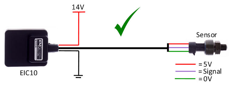
Figure 3.1. Correct MAP Sensor 0V Wiring
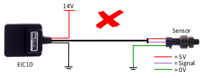
Figure 3.2. Incorrect MAP Sensor 0V Wiring
3.8 CAN Bus Wiring
- CAN Bus High and Low are differential signals, so twisted pair MUST be used. Failing to do so will compromise the entire CAN Bus System.
- In some extreme environments, shielded twisted pair may be required to help with reliability and data integrity.
- The less connectors in any transmission system the better. Unnecessary connectors are almost guaranteed to present an impedance discontinuity and hence may cause reflections and data loss.
- CAN Bus termination must be done correctly by using a 120 ohm 0.25W resistor at each END of the bus system.
- Maximum Stub length to a device from the main Bus is recommended at 0.3m, in accordance with High-Speed ISO 11898 Standard specification. See Figure 3.3.
The EIC16M device does not include an on-board CAN termination resistor, allowing the device to be wired at any position on the Bus. CAN Bus termination must be done correctly by using a 120 ohm 0.25W resistor at each end of the bus system as mentioned above. Figures 3.1 and 3.2 show possible CAN Bus Implementation examples.
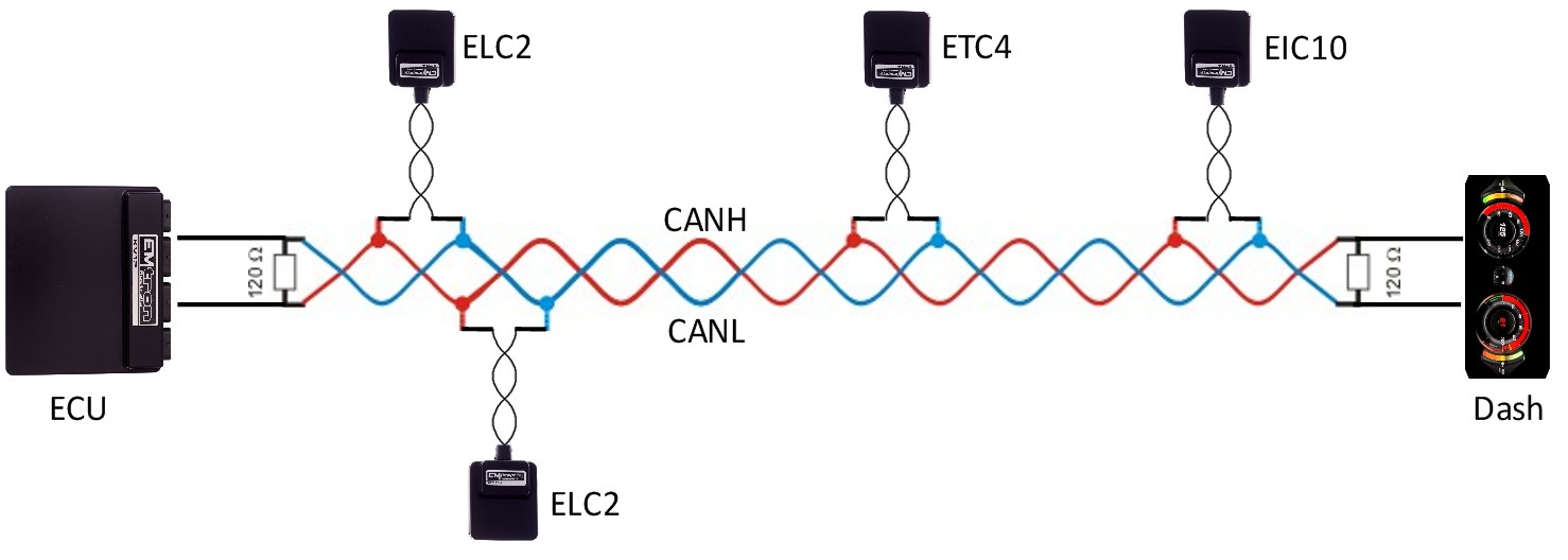
Figure 3.1. CAN Bus Wiring Example. ECU and Dash at each end with 120 Ohm Termination
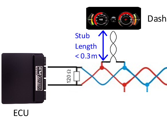
Figure 3.2. CAN Bus Wiring Example. Stub Length less than 0.3m
4.0 EIC Device Configuration
Once the EIC16M is powered and connected to the ECU’s CAN bus, the following steps should be taken to complete the setup. All setup and device monitoring is done using Emtune, so this software needs to be installed and connected to the ECU.
4.1 EIC Single Device Setup
This section outlines the setup procedure for a single device and involves 3 steps:
- Device Detection by the ECU
- ECU CAN Bus configuration
- EIC Live Data Monitoring
4.11 EIC Device Detection
To confirm the EIC device has been detected, connect to the ECU using Emtune. Open the ECU Runtime menu (F3) and select the Communications Tab. Within this tab there will be a list of Emtron CAN devices that the ECU has detected. It will list:
- CAN Device Model
- Device Serial Number
- Device Firmware Version
- Device Hardware Version
- CAN Base Address ID
With a single EIC16M device connected, the data should look as shown in Figure 4.0.
Important:
- At this stage the ECU has only detected the device. It has not been configured to an ECU CAN Channel so the EIC data is not yet available.
- Note the CAN Base Address ID. This is required in the ECU CAN setup. The factory setting is
ID 705for the EIC16M
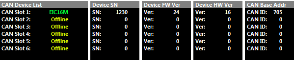 Figure 4.0. EIC16M connected to the CAN Bus
4.12 ECU CAN Configuration for Single Device
Next step is to configure an ECU CAN channel, allowing the ECU to decode the EIC CAN packets.
For this example, CAN 1- Channel 4 has been selected.
- Set “Enable" to 1(ON)”
- Set “CAN Base Address” to the Base Address shown in Figure 4.0 / 4.1. In this example select 705 for EIC16M.
- EIC16M. Set “DATA Set” to 69 (EIC16M 1x Device). See Figure 4.3
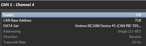
Figure 4.3. EIC16M CAN Configuration
4.13 EIC Data Monitoring for Single Device
To confirm the EIC data is being decoded by the ECU, open the ECU runtime menu (F3) -> Emtron CAN Device Tab. The EIC16M live data can be viewed. See Figure 4.4 and 4.5.
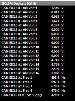
Figure 4.5. EIC16M CAN Live Data– x1 Device
4.2 EIC CAN Base Address ID Reprogramming
The default CAN Base Address can be changed at any time.
This is easily done using Emtune from the Config view -> Communications Menu -> Emtron CAN Devices -> Emtron CAN Device Programming menu. This example shows the CAN Base address being changed from the default 718 to 722.
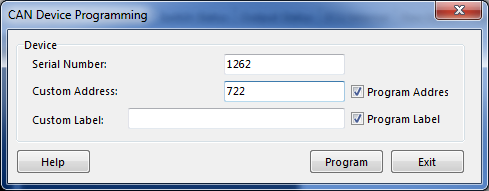
- Enter in Serial Number = 1262
- Enter new Custom Address = 722
- Make sure the “Program Address” checkbox is ticked.
- Select the “Program” button and the new Custom Address ID will be programmed into the device.
To check the device(s) have been programmed correctly with the new Base Address, open the ECU Runtime menu (F3)-> Communications Tab. Each device now has a unique Base Address ID. See Figure 4.8 shows before the program and Figure 4.9 after the program.
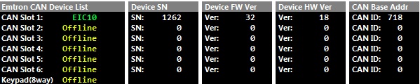
Figure 4.8. EIC CAN ID Default

Figure 4.9. EIC CAN ID Re-programmed
5.0 ECU Channel Configuration
Once the ECU has been configured to receive the EIC4/ECIC16M data, the next step is assigning the data to an ECU channel(s). The example shown in Figure 5.0 shows the following channel assignments:
- Compressor Inlet Pressure assigned to EIC16M channel 1
- Compressor Outlet Pressure assigned to EIC16M channel 2
- Compressor Inlet Temperature assigned to EIC16M channel 9
- Compressor Outlet Temperature assigned to EIC16M channel 10
NOTE: EIC16M pullup control is done through the Config View-> Communications -> Emtron CAN Devices -> Emtron Input to CAN Expansion menu. See Section 6.2 for more information.
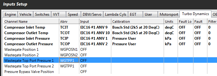
Figure 5.0
6.0 EIC Custom Settings
The EIC16M has custom settings available for:
- Transmit Rates
- Pullup configurations
- Frequency Edge selection
NOTE: When any custom EIC setting is changed, the setting is automatically stored by the EIC device and therefore used on the next power cycle.
CAN Transmit Rates
The data is separated into 3 categories and can be independently adjusted. There are:
- Analog Voltage Channels 1-12 (EIC16M)
- Analog Voltage Channels 13-16 (EIC16M)
- Frequency 1-4
For these setting see Config view-> Communications -> Emtron CAN Devices -> Emtron Input to CAN Expansion. Inside this menu will be an EIC16M menu. The Default value is 200Hz. It can be adjusted to suit the application and available CAN Bandwidth.
There are 4 options available.
- 200 Hz (Default)
- 50 Hz
- 100Hz
- 500Hz
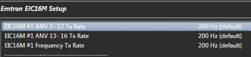
Figure 6.1. EIC16M Transmit Rate setup
Pullup Resistor Control
Section 3.5 previously summarises the Pullup options.
To adjust these setting see Config view-> Communications -> Emtron CAN Devices -> Emtron Input to CAN Expansion
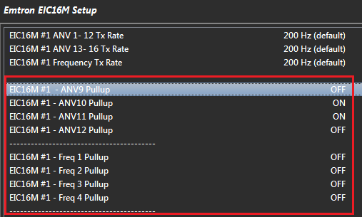
Figure 6.3. EIC16M Pullup Settings
Frequency Channel
Section 3.5 previously summarises the Frequency options. There are 3 frequency modes that can be selected:
- OFF
- Falling Edge
- Rising Edge
The Inputs can accept signals from Magnetic or Hall effect sensors. Magnetic sensors should have the edge selected to Falling. To adjust these setting see Config view-> Communications -> Emtron CAN Devices -> Emtron Input to CAN Expansion menu.
NOTE: The Frequency will not read until the Input Channel is selected to ON (i.e. Falling or Rising edge).
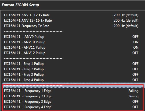
Figure 6.5. EIC16M Frequency Input Settings
7.0 Ordering Information
| Product | Part Number |
|---|---|
| Emtron EIC16M | 593-1613 |
Appendices
Appendix 1. CAN Bus Data Packaging
This section outlines the CAN Protocol used to communicate with the EIC device(s). If the device is connected to an Emtron ECU, the CAN Bus packet is automatically decoded when correct CAN Dataset is selected and no additional setup is required. For more information refer to Section 4.0.
This section provides more detailed information on the CAN ID data structure and requires an understanding of both CAN protocols and data packaging.
Baud Rate
The EIC will Auto-scan the CAN bus until a successful baud rate has been detected. Once detected this rate will be stored by the device and used at the next power up.
The device will scan 3 different Baud rates at 500ms intervals moving from 1Mbaud -> 500kBaud -> 250k Baud -> 1Mbaud and so on.
EIC16M CAN Data Format
| ID | 705 /0x2C1 (Default) |
|---|---|
| Data | Voltage 3dp |
| ID Type | Standard 11-bit identifier |
| Direction | Transmit from Device |
| Length | 8 bytes |
| Tx Rate | Adjustable (50/100/200/500 Hz) |
| CAN ID | Name | Start bit | Length (bits) | Byte Order | Data Type |
|---|---|---|---|---|---|
| 705/0x2C1 | AN Voltage 1 | 0 | 16 | Little Endian | Unsigned |
| AN Voltage 2 | 16 | 16 | Little Endian | Unsigned | |
| AN Voltage 3 | 32 | 16 | Little Endian | Unsigned | |
| AN Voltage 4 | 48 | 16 | Little Endian | Unsigned | |
| 705/0x2C1 | AN Voltage 1 | 0.001 | 0 | V | 0.0 V |
| AN Voltage 2 | 0.001 | 0 | V | 0.0 V | |
| AN Voltage 3 | 0.001 | 0 | V | 0.0 V | |
| AN Voltage 4 | 0.001 | 0 | V | 0.0 V |
| ID | 706 /0x2C2 (Default) |
|---|---|
| Data | Voltage 3dp |
| ID Type | Standard 11-bit identifier |
| Direction | Transmit from Device |
| Length | 8 bytes |
| Tx Rate | Adjustable (50/100/200/500 Hz) |
| CAN ID | Name | Start bit | Length (bits) | Byte Order | Data Type |
|---|---|---|---|---|---|
| 706/0x2C2 | AN Voltage 5 | 0 | 16 | Little Endian | Unsigned |
| AN Voltage 6 | 16 | 16 | Little Endian | Unsigned | |
| AN Voltage 7 | 32 | 16 | Little Endian | Unsigned | |
| AN Voltage 8 | 48 | 16 | Little Endian | Unsigned | |
| 706/0x2C2 | AN Voltage 5 | 0.001 | 0 | V | 0.0 V |
| AN Voltage 6 | 0.001 | 0 | V | 0.0 V | |
| AN Voltage 7 | 0.001 | 0 | V | 0.0 V | |
| AN Voltage 8 | 0.001 | 0 | V | 0.0 V |
| ID | 707 /0x2C3 (Default) |
|---|---|
| Data | Voltage 3dp |
| ID Type | Standard 11-bit identifier |
| Direction | Transmit from Device |
| Length | 8 bytes |
| Tx Rate | Adjustable (50/100/200/500 Hz) |
| CAN ID | Name | Start bit | Length (bits) | Byte Order | Data Type |
|---|---|---|---|---|---|
| 707/0x2C3 | AN Voltage 9 | 0 | 16 | Little Endian | Unsigned |
| AN Voltage 10 | 16 | 16 | Little Endian | Unsigned | |
| AN Voltage 11 | 32 | 16 | Little Endian | Unsigned | |
| AN Voltage 12 | 48 | 16 | Little Endian | Unsigned | |
| 707/0x2C3 | AN Voltage 9 | 0.001 | 0 | V | 0.0 V |
| AN Voltage 10 | 0.001 | 0 | V | 0.0 V | |
| AN Voltage 11 | 0.001 | 0 | V | 0.0 V | |
| AN Voltage 12 | 0.001 | 0 | V | 0.0 V |
| ID | 708 /0x2C4 (Default) |
|---|---|
| Data | Voltage 3dp |
| ID Type | Standard 11-bit identifier |
| Direction | Transmit from Device |
| Length | 8 bytes |
| Tx Rate | Adjustable (50/100/200/500 Hz) |
| CAN ID | Name | Start bit | Length (bits) | Byte Order | Data Type |
|---|---|---|---|---|---|
| 708/0x2C4 | AN Voltage 13 | 0 | 16 | Little Endian | Unsigned |
| AN Voltage 14 | 16 | 16 | Little Endian | Unsigned | |
| AN Voltage 15 | 32 | 16 | Little Endian | Unsigned | |
| AN Voltage 16 | 48 | 16 | Little Endian | Unsigned | |
| 708/0x2C4 | AN Voltage 13 | 0.001 | 0 | V | 0.0 V |
| AN Voltage 14 | 0.001 | 0 | V | 0.0 V | |
| AN Voltage 15 | 0.001 | 0 | V | 0.0 V | |
| AN Voltage 16 | 0.001 | 0 | V | 0.0 V |
| ID | 709 /0x2C5 (Default) |
|---|---|
| Data | Frequency 1dp |
| ID Type | Standard 11-bit identifier |
| Direction | Transmit from Device |
| Length | 8 bytes |
| Tx Rate | Adjustable (50/100/200/500 Hz) |
| CAN ID | Name | Start bit | Length (bits) | Byte Order | Data Type |
|---|---|---|---|---|---|
| 709/0x2C5 | Frequency 1 | 0 | 16 | Little Endian | Unsigned |
| Frequency 2 | 16 | 16 | Little Endian | Unsigned | |
| Frequency 3 | 32 | 16 | Little Endian | Unsigned | |
| Frequency 4 | 48 | 16 | Little Endian | Unsigned | |
| 709/0x2C5 | Frequency 1 | 0.1 | 0 | Hz | 0 |
| Frequency 2 | 0.1 | 0 | Hz | 0 | |
| Frequency 3 | 0.1 | 0 | Hz | 0 | |
| Frequency 4 | 0.1 | 0 | Hz | 0 |
| ID | 710 /0x2C6 (Default) |
|---|---|
| Data | Sensor Supply |
| ID Type | Standard 11-bit identifier |
| Direction | Transmit from Device |
| Length | 2 bytes |
| Tx Rate | 20Hz (fixed) |
| CAN ID | Name | Start bit | Length (bits) | Byte Order | Data Type |
|---|---|---|---|---|---|
| 710/0x2C6 | 5V Analog Supply | 0 | 16 | Little Endian | Unsigned |
| 710/0x2C6 | 5V Analog Supply | 0.001 | 0 | V | 0.0 V |
Appendix B. Magneto-Resistive Sensors
Magneto-resistive (MR) sensors are commonly used in driver assistance systems such as ABS, TCS and ESP to measure wheel speed, the frequency being proportional to the rotational speed of the wheel. These sensors detect a magnetic field and because there is no electrical contact the sensor can operate across a relatively large air gap. The amplitude of the output signal does not depend on speed.
These are active sensors which means they become “active” when a power supply is connected to it and a digital output waveform is then generated. However, the signal does not switch to ground like a conventional Hall sensor. Instead the signal swings between a high and low voltage, with the swing voltage dependant on the current passing through the sensor, i.e. the value of the pullup or pulldown current limiting resistor. Typical currents required to make to the sensor operate are 4 – 8mA.
Two important checks must be completed.
- The polarity of the sensor must be correct.
- The pullup/pulldown resistor might need adjustment to ensure it the digital signal swings within the correct levels. For the EIC16 this is 1.0V low and 1.8V high.
Sensor Polarity
The sensor polarity can be determined by measuring the diode voltage drop across the sensor, (sensor resistance cannot be used) using a Multimeter. The direction with the highest voltage drop is the correct polarity. See Table 6.0 as an example. Pin 1 should be connected to the pullup resistor and pin 2 should be connected the ground.
| Diode Voltage Drop | Pin 1 | Pin 2 | Notes | |
|---|---|---|---|---|
| 1.781 V | Positive | Negative | Correct Polarity | |
| 0.637 V | Negative | Positive | Incorrect Polarity |
Table 6.0
Device Connection
An MT sensor can be connected directly to an Emtron ECU and the internal Scope function can be used to view the signal. Once you have the signal image, config the pullup resistor and correctly set the arming threshold.
Due to the variation in sensor outputs the EIC Device requires an interface device to condition the signal to match the factory EIC thresholds (1.0V low and 1.8V high).
Sensor Supply and Wiring
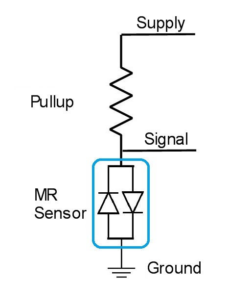
The sensor is powered through a pullup resistor. The minimum supply voltage is 8V, ideally a regulated supply should be used to ensure consistent readings. Figure 6.0 illustrates how the sensor should be wired.
NOTE: If the pullup resistor is too big there will be insufficient current to make the output switch. Typical Pullup resistor range is 330 Ohms to 1000 Ohms.
NOTE: The Low and High outputs levels will vary with different sensors, so for signal integrity each sensor output should be checked using an oscilloscope. Table 6.1 show some typical results from a Toyota Sensor
Figure 6.0. Sensor Wiring
| Supply | Pullup Resistance | Low Output | High Output | Switching Range | Comments |
|---|---|---|---|---|---|
| 5V | 330 Ohms | 5.2V | 5.2V | 0.0V | Insufficient Current |
| 8V | 330 Ohms | 3.6V | 5.9V | 2.3V | (see Figure 6.1) |
| 12V | 330 Ohms | 7.6V | 9.9V | 2.3V | |
| 8V | 470 Ohms | 5.25V | 5.25V | 0.0V | Insufficient Current |
| 12V | 470 Ohms | 6.3V | 9.45V | 3.15V |
Table 6.1
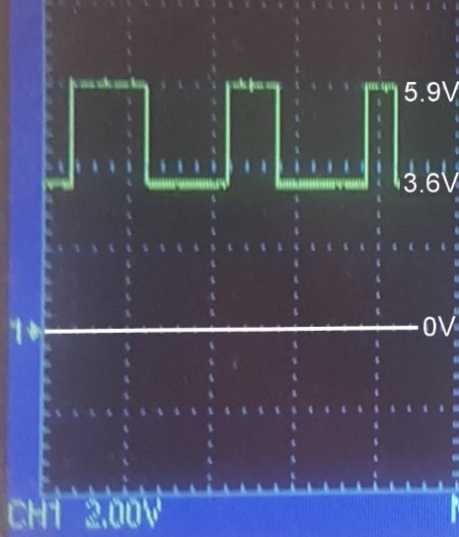
Figure 6.1 shows a scope trace of a MR Sensor with 330R pullup supplied at 8V. The High Output level is 5.9V and the Low Output Level is 3.6V.
Figure 6.1. Scope trace of MR Sensor.
Emtron Lambda to CAN
ELC1/ ELC2/ ELC2M
Kit Contents
When purchasing an ELC1/ELC2 the following items are included:
- ELC1/2 Device with Flying Harness
- Deustch DTM 4-way mating connector with female pins (DTM06-4S)
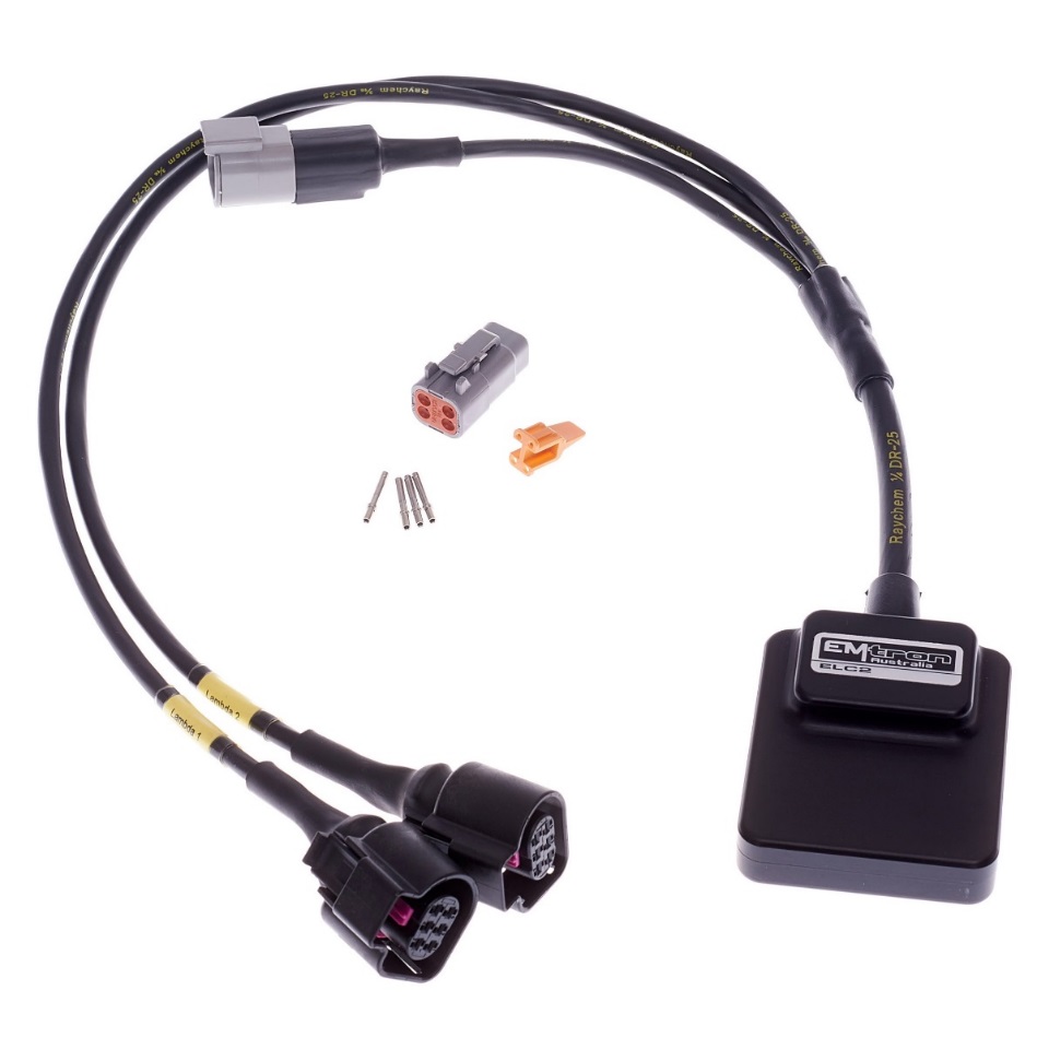
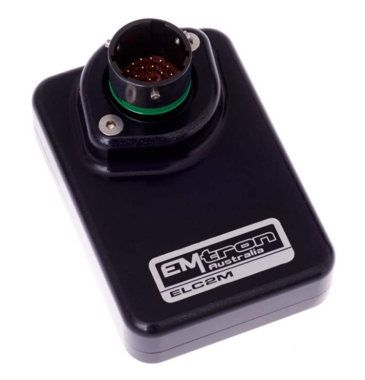
ELC2 kit pictured.
When purchasing an ELC2M the loom side mating Autosport connector is not included but can be purchased separately.
Contents
1.0 Description
The Emtron Lambda to CAN devices are available in both Standard and Mil Spec versions.
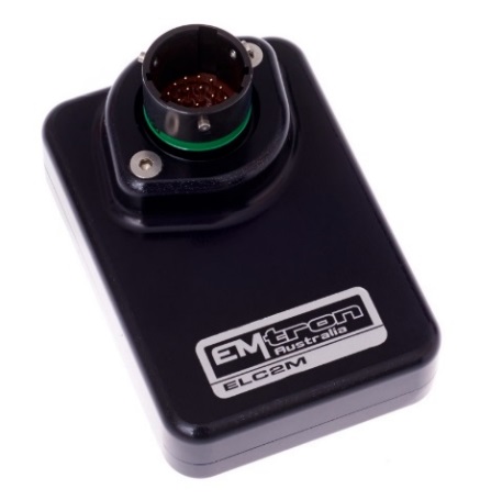
ELC2M
The ELC2M is a Mil Spec Dual Channel Lambda to CAN device using the Motorsport proven Deutsch Autosport connector system(Green). The enclosure is made from billet 6061 aluminium and is waterproof, allowing for use in extreme environments.
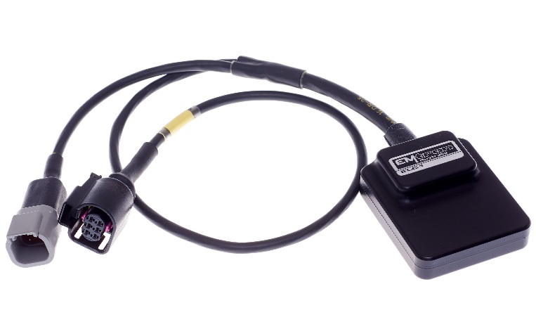
ELC1
The ELC1 is a Single Lambda to CAN device with a concentric twisted flying loom system, terminated with the reliable and environmentally sealed Deutsch DTM connector. The water proof enclosure is extremely compact and made from billet 6061 aluminium.
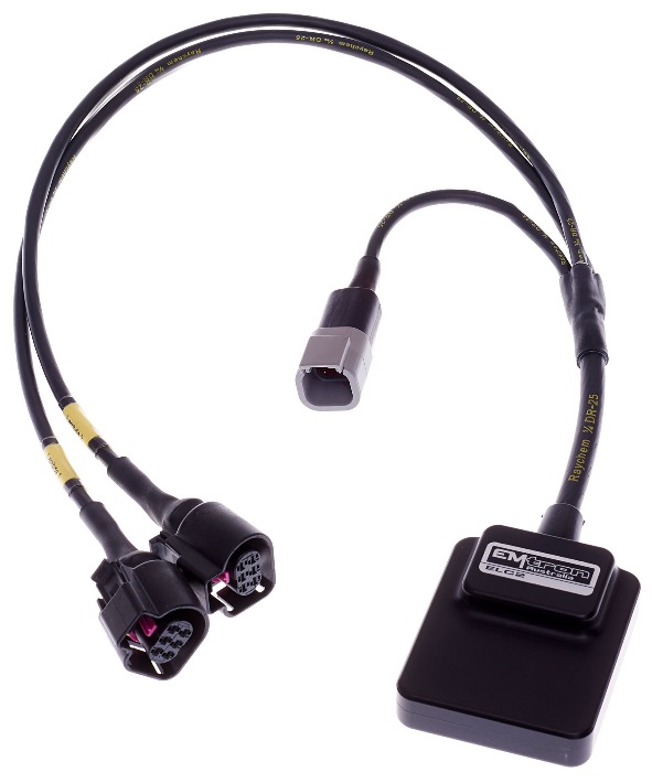
ELC2
The ELC2 is a Dual Channel Lambda to CAN device with a concentric twisted flying loom system, terminated with the reliable and environmentally sealed Deutsch DTM connector. The waterproof enclosure is extremely compact and made from billet 6061 aluminium.
All devices control the Bosch LSU4.9 Lambda Sensor and are compatible with all Emtron ECUs. Bosch proven integrated circuit technology is used for sensor control, Nernst Cell temperature measurement with advanced PID algorithms for precise heater control. Exhaust Pressure compensation is available when enabled. The device is connected to the ECU via CAN bus and will be automatically detected, significantly minimising configuration time.
2.0 Specification
Power Supply
- Operating Voltage: 7.0 to 22.0 Volts DC
- Operating Current Standby: 38mA at 14.0V
- Operating Current Average: 3A at 14.0V (Peak 8A Warmup)
- Reverse Battery Protection: 0mA current draw
- Battery Transient/Over Current Protection
Internal
- 64MHz 16-bit Automotive Processor
Inputs
- Bosch LSU4.9. Supports Single or Dual Channel
- Resolution: 0.001 Lambda
- Range: 0.580 Lambda to open air.
- Lambda Signal sampling rate: 100 Hz
- Exhaust Pressure Pump Current Compensation
Communications
- CAN 2.0B Baud Rate: 250kBaud, 500kBaud or 1Mbaud Auto Detect
- CAN Transmit Rate 100Hz
Operating Temperature
- Operating Temperature Range: -30 to 85°C (-22 to 185°F)
Physical
ELC2M
- Enclosure Size 52 mm x 74 mm x 18 mm
- 125g (Excludes loom)
ELC1/ ELC2
- Enclosure Size 63mm x 54 mm x 20mm
- ELC1 165g, ELC2 200g (includes flying loom)
3.0 Installation
Each device has a M4 x 1.5 thread tapped into the base of the enclosure and can be used for mounting. In high vibration applications rubber mounting is recommended.
CAUTION When mounting the device inside the engine compartment, it should be positioned in cooler areas and away from heat sources such as exhaust manifolds. Any unnecessary radiated heat may affect device performance.
3.1 ELC1/2 Wiring
The pinouts are shown below in Table 3.0 and Table 3.1.
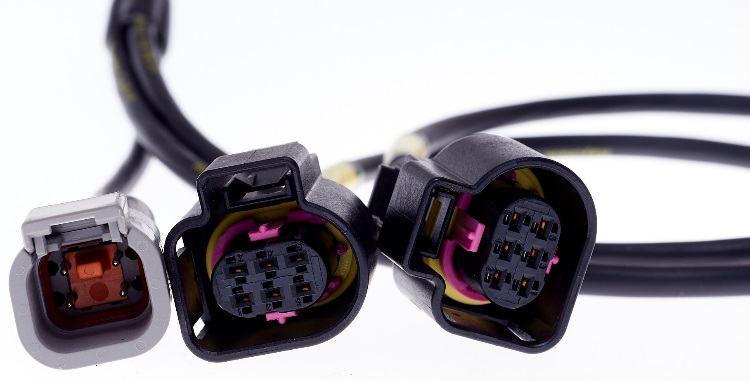 Power and CAN Flying Loom Connector: DTM 4 pin (M).
| Pin | Function |
|---|---|
| 1 | Ground |
| 2 | CAN Lo |
| 3 | CAN Hi |
| 4 | 12V Supply |
Table 3.0. ELC Power and CAN Deustch Connector Pinout
Lambda Flying Loom Connector: Bosch LSU 4.9 (F)
| Pin | Function | Wire Colour |
|---|---|---|
| 1 | Pump Current | Red |
| 2 | Virtual Ground | Yellow |
| 3 | Heater Ground | White |
| 4 | Heater 12 Supply | Grey |
| 5 | Cal Resistor | Orange |
| 6 | Nernst Cell Voltage | Black |
Table 3.1 ELC1/2 LSU 4.9 Connector Pinout
3.2 ELC2M Wiring
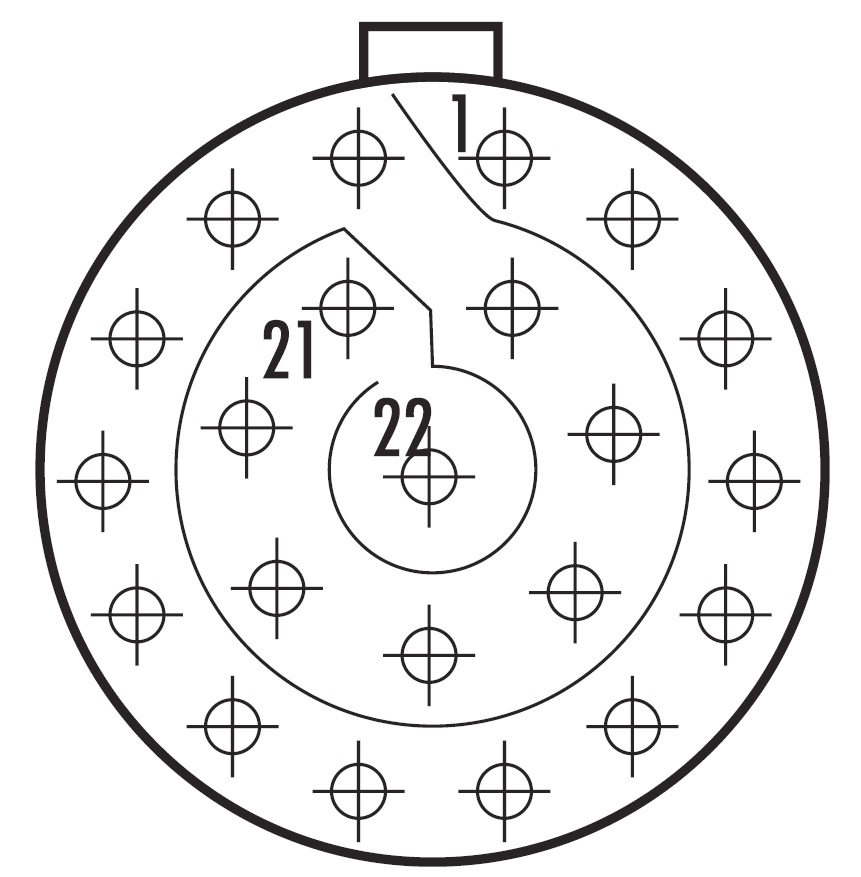
| Mating Connector Loom Side (Deutsch Autosport AS Series) |
|---|
| AS612-35PD (Green) |
| Pin | Function | Bosch Datasheet Reference |
|---|---|---|
| 1 | 14 V Supply | |
| 2 | Ground | |
| 3 | CAN Hi | |
| 4 | CAN Lo | |
| 5 | Lambda 1 Pump Current | APE |
| 6 | Lambda 1 Nernst Cell Voltage | RE |
| 7 | Lambda 1 Cal Resistor | |
| 8 | Lambda 1 Virtual Ground | IPN |
| 9 | Lambda 2 Pump Current | APE |
| 10 | Lambda 2 Nernst Cell Voltage | RE |
| 11 | Lambda 2 Cal Resistor | |
| 12 | Lambda 2 Virtual Ground | IPN |
| 13 | Lambda 1 Heater Ground | |
| 14 | Lambda 2 Heater Ground | |
| 15 | Lambda 1 Heater 14V Supply (Protected) | |
| 16 | Lambda 2 Heater 14V Supply (Protected) | |
| 17 | (Not used) | |
| 18 | (Not used) | |
| 19 | (Not used) | |
| 20 | (Not used) | |
| 21 | (Not used) | |
| 22 | (Not used) |
Table 3.2. ELC2M Pinout
3.3 Bosch LSU4.9 Sensor Wiring
Lambda Connector: Bosch LSU 4.9 (F)
| Pin | Function | Wire Colour |
|---|---|---|
| 1 | Pump Current | Red |
| 2 | Virtual Ground | Yellow |
| 3 | Heater Ground | White |
| 4 | Heater 12 Supply | Grey |
| 5 | Cal Resistor | Orange |
| 6 | Nernst Cell Voltage | Black |
Table 3.3. Bosch LSU 4.9 Sensor Pinout
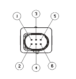

Figure 3.0. LSU4.9 Connector Pinout
NoteTo avoid signal errors and loss of accuracy, a cable of a maximum length of 1.5 m between sensor and ELC is recommended.3.4 CAN Bus Wiring
- CAN Bus High and Low are differential signals, so twisted pair MUST be used. Failing to do so will compromise the entire CAN Bus System.
- In some extreme environments, shielded twisted pair may be required to help with reliability and data integrity.
- The less connectors in any transmission system the better. Unnecessary connectors are almost guaranteed to present an impedance discontinuity and hence may cause reflections and data loss.
- CAN Bus termination must be done correctly by using a 120 ohm 0.25W resistor at each END of the bus system.
- Maximum Stub length to a device from the main Bus is recommended at 0.3m, in accordance with High-Speed ISO 11898 Standard specification. See Figure 3.3.
The ELC devices do not include an on-board CAN termination resistor, allowing the device to be wired at any position on the Bus. CAN Bus termination must be done correctly by using a 120 ohm 0.25W resistor at each end of the bus system as mentioned above. Figures 3.1 and 3.2 show possible CAN Bus Implementation examples
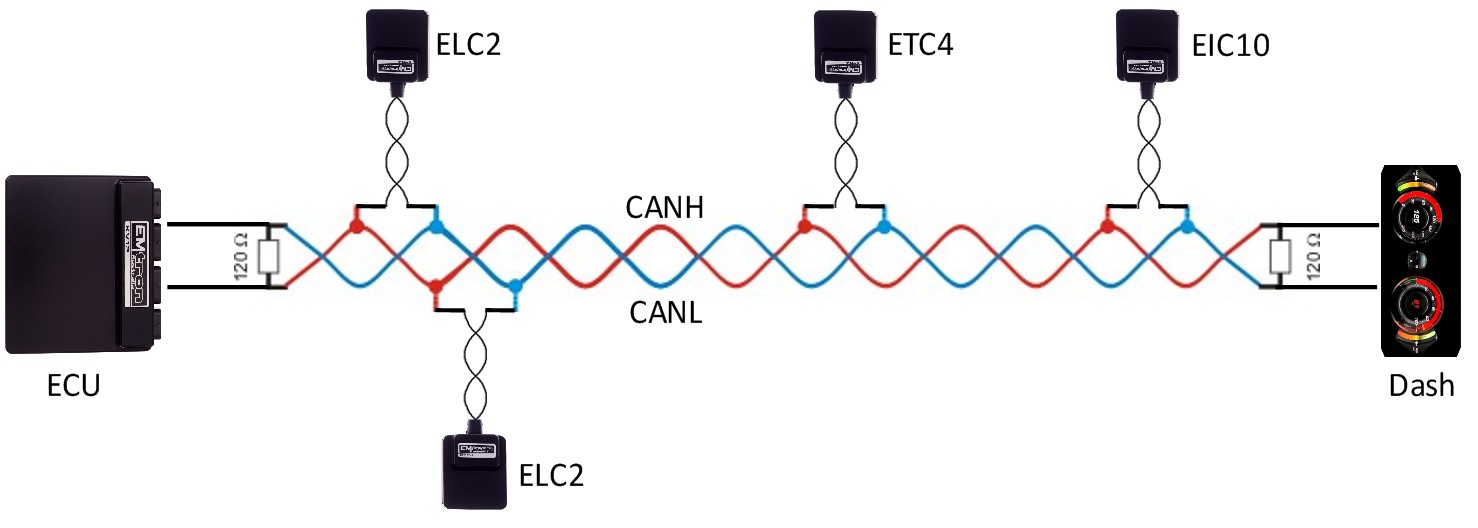
Figure 3.1. CAN Bus Wiring Example. ECU and Dash at each end with 120 Ohm Termination
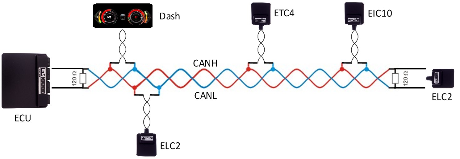
Figure 3.2. CAN Bus Wiring Example. ECU and ELC2 at each end with 120 Ohm Termination
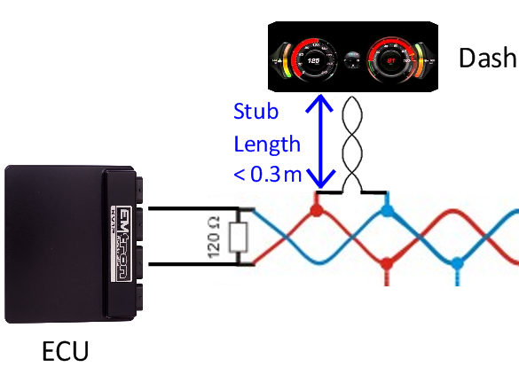
Figure 3.3. CAN Bus Wiring Example. Stub Length less than 0.3m
3.5 ELC CAN Bus
The ELC devices can be connected to the ECUs CAN Bus 1 or 2.
All devices on the CAN Bus must be configured to use the same baud rate. For this reason, all Emtron CAN devices will Auto-scan the CAN bus until a successful baud rate has been detected. Once detected this rate will be stored and used at the next power up.
The device will scan 3 different Baud rates at 500ms intervals moving from 1Mbaud -> 500kBaud -> 250k Baud -> 1Mbaud and so on.
NOTE: For this process to function effectively, when new devices are introduced to the CAN bus, they should initially be connected one at a time. This allows each device to sync up to the CAN Bus baud rate and store that setting. This typically takes 3-5 seconds.
The ELC devices leave the factory programmed with individual serial numbers, but all have the same Base CAN Address ID used to transmit data over the Bus. The CAN Base address can be adjusted from the factory setting using the ID Reprogramming Tool. This is required when 2 or more of the same devices are connected to the CAN Bus (See section 4.2).
- Factory CAN Base Address of 671. Transmits data sequentially on the next ID. Total CAN ID Range is therefore 671 – 672.
- Up to 6x ELC devices (ELC or ELCM) can be used on the CAN Bus giving a total of 12 available Lambda Channels.
3.6 Noise Immunity
To minimise signal contamination and maximise noise immunity, the wire pairs shown in Table 3.2 must be twisted. It is recommended to twist the wire pairs at a minimum one twist per 40mm of cable. This is very important and should always be implemented on both CAN Bus and LSU Sensor wiring.
| Pair 1 | Pair 2 | |
|---|---|---|
| CAN High | <——-> | CAN Low |
| Pump Current | <——-> | Cal Resistor |
| Nernst Cell Voltage | <——-> | Virtual Ground |
Table 3.4. Wire pairing for twisting
4.0 Lambda Sensor Installation
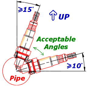
Installation angle must be inclined at least 10° towards horizontal, (electrical connection upwards) up to a maximum of 75°. This prevents the collection of liquids between sensor housing and sensor element during the cold start phase.
The angle against the exhaust gas stream should be aimed as 90°. Maximum inclination should be 90°+15° (protection tube towards gas stream) or 90°-30°.
NOTE: NEVER mount the sensor directly on the horizontal or within 10 degrees of the horizontal. Doing so will result in intermittent sensor shutdown.
Also route the sensor cable to avoid high moisture locations – just a small amount of moisture is enough to provide a conductive path within the connector that will upset measurement from the sensor.
Winter and salted roads compound this issue. Always check for a cracked or broken connector when strange results occur.
5.0 Heater Control and Sensor Calibration
5.1 Heater Control
During engine start-up, condensation forms in the exhaust which may damage the sensor. It is recommended to only start heating the LSU sensor after the engine is running and the moisture content in the exhaust has evaporated. ELC settings allow the ECU to control heater setup if enabled.
For maximum sensor life the ECU should control heater start-up. It does this by communicating with the ELC over CAN Bus. For setup options see Config View -> Communications Tab -> Emtron CAN Device -> Emtron Lambda to CAN (ELC/ELCM) Setup. See Figure 5.0.
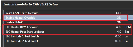
Figure 5.0. Emtune ELC Setup menu - Heater Control
Once changed, the settings are automatically stored by the ELC and therefore used on the next power cycle. If the CAN bus is not used to control the heater (Enable Heater Override = OFF), then by default the heater remains OFF for 15 seconds after the device is powered up.
5.2 Sensor Calibration
The sensor is calibrated by the ELC on power up. During the Calibration process two important pieces of data are read:
- The optimal Nernst Cell Temperature which is used for sensor heater control. The ELC applies duty cycle and a PID routine to maintain a constant and accurate heater temperature which results in a very stable and accurate Lambda value.
- The Pump Current that corresponds to a Lambda reading of 1.000 Lambda.
NOTE: A Free-Air Calibration is NOT required on the LSU4.9. The sensor uses a reference pump current instead of reference air. The big advantage with this is that the reference is a calibrated electrical signal and remains constant.
6.0 Exhaust Back Pressure (EMAP) Compensation
Wideband Lambda sensors primarily count oxygen atom numbers through measuring the oxygen ion current within the sensors pump cell. The exhaust gas pressure affects this oxygen ion current. The more pressure means more atoms per unit volume and a higher pump current at the same Lambda i.e. this will cause the sensor to read farther from stoichiometric.
A rich reading will appear richer than it really is.
A lean reading will appear leaner than it really is.
This predominantly becomes an issue in Turbocharged applications. This is the main reason you should position the sensor after the turbo where exhaust back-pressure is lowest.
Excessive Exhaust Back Pressure (EMAP) can also damage the sensor. The following rule should be observed:
Exhaust Back Pressure < 2.5 Bar
When measuring Exhaust Back Pressure, an Absolute Pressure Sensor MUST be used. (i.e. do not use a Gauge Pressure Sensor). The ECU MUST have the Exhaust Manifold Pressure channel configured so data transmitted from ECU to ELC is valid.
The EMAP setting can be enabled by going to the the Config View -> Communications Tab -> Emtron CAN Device -> Emtron Lambda to CAN (ELC/ELCM) Setup and selecting the “Enable EMAP” setting to ON (Figure 6.0). Once enabled to ECU will transmit the EMAP value over the CAN Bus and the ELC will received this value so the correction can be applied.
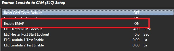
Figure 6.0. Emtune ELC setup menu - EMAP Enable
NOTE: Once changed, the setting is automatically stored by the ELC and therefore used on the next power cycle.
7.0 ELC Device Configuration
Once the ELC is powered and connected to the ECU’s CAN bus, the following steps should be taken to complete the setup. All setup and device monitoring is done using Emtune so this software needs to be installed and connected to the ECU.
7.1 ELC Single Device Setup
This section outlines the setup procedure for a single device and involves 2 steps:
- Device Detection by the ECU
- ECU CAN Bus configuration
7.11 ELC Device Detection
To confirm the ELC device has been detected, connect to the ECU using Emtune. Open the ECU Runtime menu (F3) and select the Communications Tab. Within this tab there will be a list of Emtron CAN devices the ECU has detected. It will list:
- CAN Device Model
- Device Serial Number
- Device Firmware Version
- Device Hardware Version
- CAN Base Address ID
With a single ELC device connected, the data should look as shown in Figure 7.0/7.1.
Important:
- At this stage the ECU has only detected the device. It has not been configured to an ECU CAN Channel so the ELC data is not yet available.
- Note the CAN Base Address ID. This is required in the ECU CAN setup. The factory setting is ID 671 for the ELC and ELC2M.
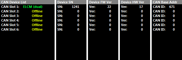
Figure 7.0. Example ELC2M device detected by the ECU.
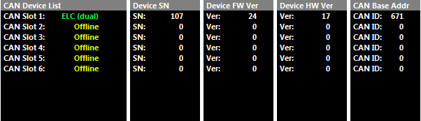
Figure 7.1. Example ELC2 device detected by the ECU
7.12 ECU CAN Channel Configuration for Single Device
The next step is to configure an ECU CAN channel, allowing the ECU to decode the ELC CAN packets.
For this example, CAN 1- Channel 1 has been selected.
- Set “Enable” to (ON)
- Set “CAN Base Address” to the ID shown in Figure 7.0/7.1 In this example its ID 671.
- Set “DATA Set” to 50 (ELC/ELC2M 1x Device). See Figure 7.2.
The ECU in now configured and reading the data from the ELC Device.

Figure 7.2. ELC CAN Configuration
7.2 ELC Multiple Device Setup
As mentioned in section 3.5, the Base CAN Address ID used to transmit Data over the Bus by default is the same for each device type. The ELC has a factory CAN Base Address of 671. When multiple ELC devices are installed on the same CAN Bus, each device MUST have a unique CAN Base Address to avoid Bus conflicts. This means the CAN Base Address ID will need to be reprogrammed which is a simple task using the ID Reprogramming Tool as outlined in section 7.22.
REMEMBER: For this process to function effectively, when multiple new devices are introduced to the CAN bus, they should initially be connected one at a time. This allows each device to sync up to the CAN Bus baud rate and store that setting. This usually takes 3-5 seconds.
7.21 ELC Multiple Device Detection
To confirm the ELC device has been detected, connect to the ECU using Emtune. Open the ECU Runtime menu (F3) and select the Communications Tab. Within this tab there will be a list of Emtron CAN devices the ECU has detected. It will list:
- CAN Device Model
- Device Serial Number
- Device Firmware Version
- Device Hardware Version
- CAN Base Address
With multiple ELC devices connected, the CAN Summary List should look as shown in Figure 7.3. In this example x2 ELC2 devices are connected to the BUS. Device 1 with SN 1241 and Device 2 with SN 1242.

Figure 7.3. Example show two ELC2 Devices detected by the ECU
Note: ALL devices have the same Base Address of ID 671, which is the factory setting for a single device. To avoid Bus conflicts, the factory base address needs to be changed when multiple devices are used, to ensure each device has its own unique ID. When re-programming the Base Address for each device the IDs MUST be:
- Sequential in order.
- Have a gap of 2 numbers between each ELC device.
The Base Address ID can be any number but Emtron recommends the following:
- ELC Device 1: ID Base Address 671. (CAN ID Range 671-672)
- ELC Device 2: ID Base Address 722. (CAN ID Range 673-674)
- ELC Device 3: ID Base Address 722. (CAN ID Range 675-676)
- ELC Device 4: ID Base Address 722. (CAN ID Range 677-678)
- ELC Device 5: ID Base Address 722. (CAN ID Range 679-680)
- ELC Device 6: ID Base Address 722. (CAN ID Range 681-682)
7.22 ELC CAN Base Address ID Reprogramming
To ensure each ELC device has a unique ID from the example in Figure 7.3, ELC2 Device 2 (SN 1242) needs a new Base Address of 673.
This is easily done using Emtune from the Config view -> Communications Menu -> Emtron CAN Devices -> Emtron CAN Device Programming menu
In this example, ELC Device 2 will need to have its Base Address re-programmed to 673. This is easily done using Emtune from the Config view -> Communications Menu -> Emtron CAN Devices -> Emtron CAN Device Programming menu. In this example select:
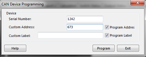
Device 2 ID Reprogramming
Enter in Serial Number = 1242
Enter in Custom Address = 673
Make sure the “Program Address” checkbox is ticked.
Select the “Program” button and the new Custom Address ID will be programmed into the device.
To check the device has been correctly programmed with the new CAN Base Address, open the F3 menu -> Communications Tab. CAN device 2 with SN 1242 should have a new Base Address of 673. See Figure 7.5
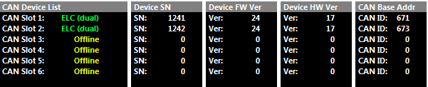
Figure 7.5. 2x ELC Devices detected by the ECU with reprogrammed IDs
7.23 ECU CAN Configuration for Multiple Devices
The next step is to configure an ECU CAN channel, allowing the ECU to decode the ELC CAN packets.
Only 1 CAN Channel is required for multiple devices. CAN 1 - Channel 4 has been selected. Config as follows:
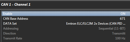 Set “Enable" to 1(ON)”
- Set “CAN Base Address” to the Lowest Base Address ID shown in Figure 7.5. In this example its 671.
- Set “DATA Set” to 51 -Emtron ELC/ELCM 2x Devices (CAN PID 671/673).
The ECU is now configured and will receive data from all devices on IDs 671-672, 673-674.
NOTE: You only need to program in the lowest Base Address . The ECU automatically configures the remaining IDs based on the assumption that the IDs are sequential in order.
8.0 ECU Channel Configuration
Once the ECU has been configured to receive the ELC data, the next step is assigning the data to an ECU lambda channel(s). There are several options:
Option A: Use the Lambda 1 and Lambda 2 Input Channel(s) as shown in Figure 8.0. With a ELC1 set the Lambda 1 to CAN ELC #1 Ch-A and for an ELC2 set Lambda 1 to CAN ELC #1 Ch-A and Lambda 2 to CAN ELC #1 Ch-B.
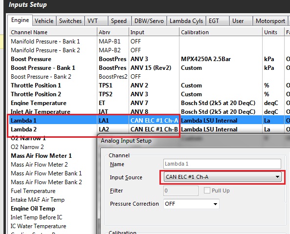
Figure 8.0.
When this option is used the Runtime menu (F3) -> Lambda tab can be used to view the data from both channels. This includes Lambda data and Diagnostics data to help with fault finding should any issues occur. See Figure 8.1.
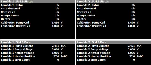
Figure 8.1
Options B: Use the Lambda Cylinder Input Channels. This setup is normally done when multiple ELC devices are used to measure the lambda on individual cylinders. Figure 8.2 shows four ELC devices configured, measuring the individual Lambda on an 8-cylinder engine. Example setup:
- To configure the ELC Device 1:
- Channel A to Cylinder 1; set the Channel Input Source for Lambda Cyl 1 to CAN ELC #1 Ch-A
- Channel B to Cylinder 2; set the Channel Input Source for Lambda Cyl 2 to CAN ELC #1 Ch-B
- To configure the ELC Device 2:
- Channel A to Cylinder 3; set the Channel Input Source for Lambda Cyl 3 to CAN ELC #2 Ch-A
- Channel B to Cylinder 4; set the Channel Input Source for Lambda Cyl 4 to CAN ELC #2 Ch-B
… etc for ELC Device 3 and 4
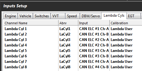
Figure 8.2. Multiple ELC devices channel assignments
9.0 ELC Custom Device Settings
The following settings are available to control the ELC. These settings get applied to ALL ELC devices connected on the CAN bus.
- Reset CAN IDs to Default
- Enable Heater Override (See Section 5.0)
- Enable EMAP (See Section 6.0)
- ELC Heater RPM Lockout (See Section 5.0)
- ELC Heater Post Start Lockout (See Section 5.0)
- ELC Lambda 1 Test Enable
- ELC Lambda 2 Test Enable
These settings are available from the Config View -> Communications Tab -> Emtron CAN Device -> Emtron Lambda to CAN (ELC/ELCM) Setup". See Figure 9.0
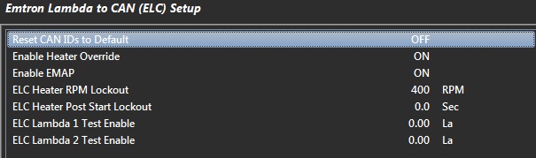
Figure 9.0
The ELC Lambda 1 and 2 Test Enable setting will force the ELC device to send the Test Lambda value over the CAN bus. The ECU will read that value and it’s a simple way of confirming the system is calibrated correctly. Make sure this setting is reset back to zero when finished.
NOTE: When any custom ELC setting is changed, the setting is automatically stored by the ELC device and therefore used on the next power cycle.
10.0 Ordering Information
| Product | Part Number |
|---|---|
| Emtron ELC1 | 5123-1 |
| Emtron ELC2 | 5123-2 |
| Emtron ELC2M | 5123-213 |
Appendices
Appendix 1 – CAN Bus Data Packaging
This section outlines the CAN Protocol used to communicate with the ELC device(s). If the device is connected to an Emtron ECU, the CAN Bus packet is automatically decoded when CAN ELC Dataset is selected and no additional setup is required. For more information refer to Section 7.0.
This section provides more detailed information on the CAN ID data structure and requires an understanding of both CAN protocols and data packaging.
Baud Rate
The device will Auto-scan the CAN bus until a successful baud rate has been detected. Once detected this rate will be stored by the device and used at the next power up.
The device will scan 3 different Baud rates at 500ms intervals moving from 1Mbaud -> 500kBaud -> 250k Baud -> 1Mbaud and so on.
ELC CAN Data Format
| ID | 671 /0x28F (Default) |
|---|---|
| Data | Lambda Channel 1 |
| ID Type | Standard 11-bit identifier |
| Direction | Transmit from Device |
| Length | 8 bytes |
| Tx Rate | 100Hz/10ms |
| CAN ID | Name | Start bit | Length (bits) | Byte Order | Data Type |
|---|---|---|---|---|---|
| 671/0x28F | Index = 0 | 0 | 8 | Little Endian | Unsigned |
| Lambda 1 | 8 | 16 | Little Endian | Unsigned | |
| Pump Current 1 | 24 | 16 | Little Endian | Signed | |
| Fault 1 | 40 | 8 | Little Endian | Unsigned | |
| Status 1 | 48 | 8 | Little Endian | Unsigned | |
| Heater 1 DC | 56 | 8 | Little Endian | Unsigned |
Continuation:
| CAN ID | Name | Multiplier | Offset | Units | Example |
|---|---|---|---|---|---|
| 671/0x28F | Index = 0 | 1 | 0 | ||
| Lambda 1 | 0.001 | 0 | La | 897 = 0.897 La | |
| Pump Current 1 | 0.001 | 0 | mA | 132 = 0.132mA | |
| Fault 1 | 1 | 0 | |||
| Status 1 | 1 | 0 | |||
| Heater 1 DC | 1 | 0 | % | 42 = 42%DC |
| ID | 672 /0x290 (Default) |
|---|---|
| Data | Lambda Channel 2 |
| ID Type | Standard 11-bit identifier |
| Direction | Transmit from Device |
| Length | 8 bytes |
| Tx Rate | 100Hz/10ms |
| CAN ID | Name | Start bit | Length (bits) | Byte Order | Data Type |
|---|---|---|---|---|---|
| 672/0x290 | Index = 0 | 0 | 8 | Little Endian | Unsigned |
| Lambda 2 | 8 | 16 | Little Endian | Unsigned | |
| Pump Current 2 | 24 | 16 | Little Endian | Signed | |
| Fault 2 | 40 | 8 | Little Endian | Unsigned | |
| Status 2 | 48 | 8 | Little Endian | Unsigned | |
| Heater 2 DC | 56 | 8 | Little Endian | Unsigned |
Continuation:
| CAN ID | Name | Multiplier | Offset | Units | Example |
|---|---|---|---|---|---|
| 672/0x290 | Index = 0 | 1 | 0 | ||
| Lambda 2 | 0.001 | 0 | La | 897 = 0.897 La | |
| Pump Current 2 | 0.001 | 0 | mA | 132 = 0.132mA | |
| Fault 2 | 1 | 0 | |||
| Status 2 | 1 | 0 | |||
| Heater 2 DC | 1 | 0 | % | 42 = 42%DC |
| Fault 1/2 – Start BIT 40 Length 8 BITS | |
|---|---|
| Bit 0/1: Virtual Ground | 0 = Error: Short to ground 1 = Error: IC Power Supply Low 2 = Error: Short to Vbatt 3 = Ok |
| Bit 2/3: Nernst Cell | 0 = Error: Short to ground 1 = Error: IC Power Supply Low 2 = Error: Short to Vbatt 3 = Ok |
| Bit 4/5: Pump Current | 0 = Error: Short to ground 1 = Error: IC Power Supply Low 2 = Error: Short to Vbatt 3 = Ok |
| Bit 6/7: Heater | 0 = Error: Short to ground 1 = Error: IC Open Load 2 = Error: Short to Vbatt 3 = Ok |
| Status 1/2 - Start BIT 48 Length 8 BITS |
|---|
| 0 = OFF |
| 1 = Normal Operation |
| 2 = Sensor Warming up |
| 3 = RPM Lockout (when available) |
| 4 = Post Start Lockout (when available) |
| 5 = Reading Calibration Data |
| 14 = Heater Under Temperature (cannot reach 650 DegC) |
| 15 = Heater Over Temperature |
| 16 = Sensor Shutdown - Thermal Shock |
| 17 = Cannot read Chip ID |
| 18 = Set Pump reference command Invalid |
| 19 = Calibrate Command Invalid |
| 20 = Standalone Command Invalid |
| 21 = Nernst Cal Data Invalid |
| 22 = Pump Cal Data Invalid |
| 19 = Lambda Stability Error |
| 20 = Error Reading Chip ID |
| 22 = System Voltage Low |
| 22 = Cannot enter Calibration mode |
| 23 = Cannot enter standalone mode |
Emtron Thermocouple to CAN (ETC4 / ETC8M)
Kit Contents — When purchasing an ETC4 the following items are included:
- ETC4 Device with Flying Harness
- Deutsch DTM 4-way connector and female pins (DTM06-4S)
- Deutsch DTM 12-way connector and male pins (DTM04-12PA)
1.0 Description
The Emtron Thermocouple (EGT) to CAN devices are available in both Standard and Mil Spec versions.
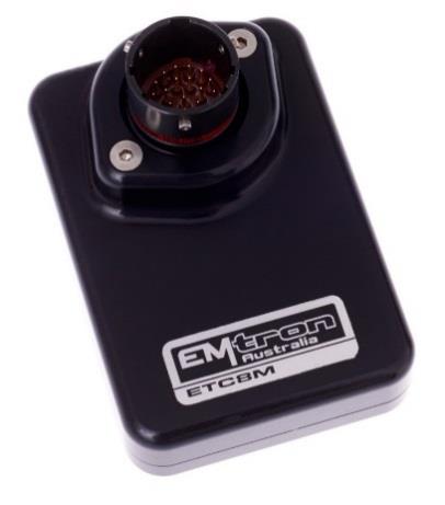
ETC8M — Mil Spec 8 channel Thermocouple to CAN device with Deutsch Autosport connector.
ETC8M — The ETC8M is a Mil Spec 8 Channel Thermocouple to CAN device using the Motorsport-proven Deutsch Autosport connector (Red). The enclosure is made from billet 6061 aluminium and is waterproof to allow for implementation in extreme environments.
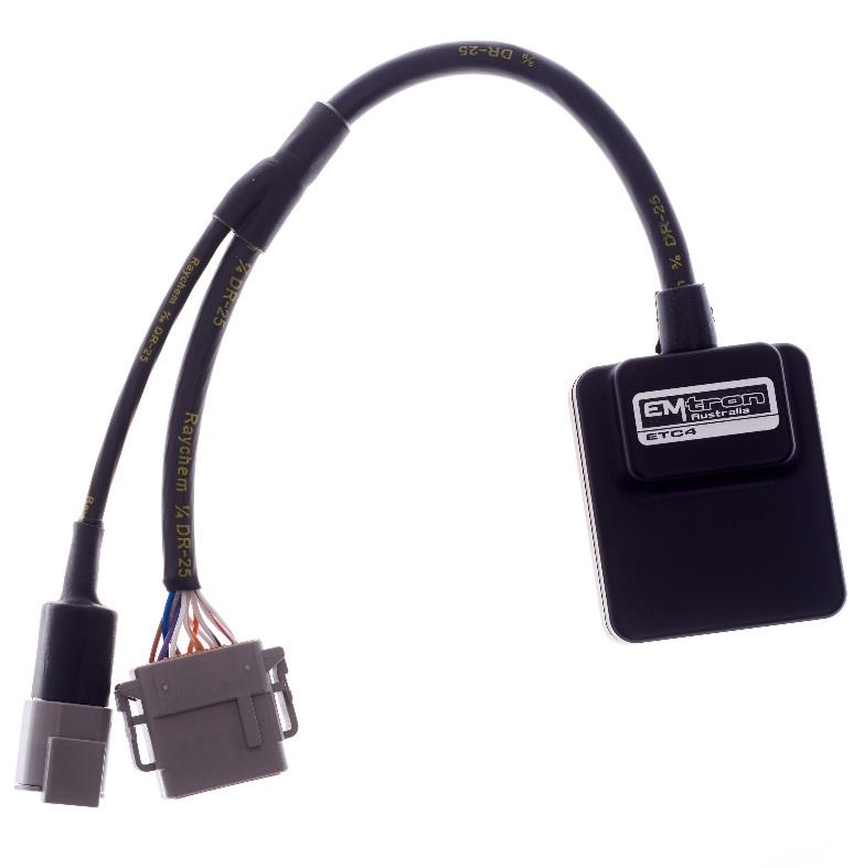
ETC4 — 4 channel Thermocouple to CAN device with Deutsch DTM connectors.
ETC4 — The ETC4 is a 4 channel Thermocouple to CAN device with a concentric twisted flying loom system, terminated with the reliable and environmentally sealed Deutsch DTM connector. The waterproof enclosure is extremely compact and made from billet 6061 aluminium.
Both devices accurately measure the exhaust gas temperature or cylinder head temperature using K-type thermocouples with a range of -50 to 1350 Degrees Celsius. The device is connected to the ECU via CAN bus and will be automatically detected, significantly minimising configuration time.
2.0 Specification
Power Supply
- Operating Voltage: 7.0 to 22.0 Volts DC
- Operating Current: 25mA (ETC4) and 30mA (ETC8M) at 14.0V
- Reverse Battery Protection: 0mA current draw
- Battery Transient/Over Current Protection
Internal
- 64MHz 16-bit Automotive Processor
- Instrumentation Amplifier for K-Type voltage measurement with precise gain control and protected inputs
- Built-in cold junction compensation
- Thermocouple open circuit fault detection
Inputs - General
- K-Type Thermocouple Inputs — Range: -50 to 1350°C, Resolution 1°C
- Sampling rate 500 Hz — Resolution: 1.22mV (12 Bit)
- Internal or External Cold Junction Correction — Range: -50 to 150°C, Resolution 1°C
- ETC8M: 8× K-Type Thermocouple Inputs, 1× External Cold Junction Input
- ETC4: 4× K-Type Thermocouple Inputs, 1× External Cold Junction Input
Communications
- CAN 2.0B Baud Rate: 250kBaud, 500kBaud or 1Mbaud Auto Detect
- CAN Transmit Rate Adjustable: 50Hz / 100Hz / 200Hz / 500Hz
Operating Temperature: -30 to 100°C (-22 to 212°F)
Physical
- ETC8M: Enclosure Size 52 × 74 × 18 mm, 125g
- ETC4: Enclosure Size 63 × 54 × 20 mm, 160g
3.0 Installation
Each device has an M4 × 1.5 thread tapped into the base of the enclosure and can be used for mounting. In high vibration applications rubber mounting is recommended.
WarningCAUTION When mounting the device inside the engine compartment, it should be positioned in cooler areas and away from heat sources such as exhaust manifolds. Any unnecessary radiated heat may affect device performance.
3.1 ETC4 Pinout
Table 3.0 — ETC4 Power and CAN Deutsch Connector (DTM 4 pin, M)
| Pin | Function | Wire Colour |
|---|---|---|
| 1 | Ground | BLACK |
| 2 | CAN Lo | GREEN |
| 3 | CAN Hi | YELLOW |
| 4 | 12V Supply | RED |
Table 3.1 — ETC4 Thermocouple Flying Loom Connector (DTM 12 pin, F — DTM06-12SA)
| Pin | Function | Wire Colour |
|---|---|---|
| 1 | EGT 1+ | BRN |
| 2 | EGT 2+ | BLUE |
| 3 | EGT 3+ | GREY |
| 4 | EGT 4+ | W/GREY |
| 5 | NC | W/BLUE |
| 6 | External Cold Junction | W/BRN |
| 7 | Analog Sensor 0V Reference | W/RED |
| 8 | NC | W/BLACK |
| 9 | EGT 4- | W/OR |
| 10 | EGT 3- | OR |
| 11 | EGT 2- | WHITE |
| 12 | EGT 1- | PUR |
3.2 ETC8M Pinout
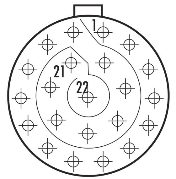
ETC8M Deutsch Autosport AS Series connector. Mating connector loom side: AS612-35SN (Red).
Table 3.2 — ETC8M Pinout
| Pin | Function | Pin | Function |
|---|---|---|---|
| 1 | 14 V Supply | 12 | EGT 4+ |
| 2 | Ground | 13 | EGT 5- |
| 3 | CAN Hi | 14 | EGT 5+ |
| 4 | CAN Lo | 15 | EGT 6- |
| 5 | EGT 1- | 16 | EGT 6+ |
| 6 | EGT 1+ | 17 | EGT 7- |
| 7 | EGT 2- | 18 | EGT 7+ |
| 8 | EGT 2+ | 19 | EGT 8- |
| 9 | EGT 3- | 20 | EGT 8+ |
| 10 | EGT 3+ | 21 | Cold Junction Input (External) |
| 11 | EGT 4- | 22 | 0V Analog Sensor Reference |
3.3 CAN Bus
The ETC4 or ETC8M can be connected to the ECU’s CAN Bus 1 or 2. All devices on the CAN Bus must be configured to use the same baud rate. For this reason, all Emtron CAN devices will auto-scan the CAN bus until a successful baud rate has been detected. Once detected this rate will be stored and used at the next power up. The device will scan 3 different baud rates at 500ms intervals moving from 1Mbaud → 500kBaud → 250kBaud → 1Mbaud and so on.
NoteNOTE For this process to function effectively, when new devices are introduced to the CAN bus, they should initially be connected one at a time. This allows each device to sync up to the CAN Bus baud rate and store that setting. This typically takes 3-5 seconds.
The ETC4 and ETC8M leave the factory programmed with individual serial numbers, but all have the same Base CAN Address ID used to transmit data over the Bus. The CAN Base address can be adjusted from the factory setting using the ID Reprogramming Tool. This is required when 2 or more of the same devices are connected to the CAN Bus (see section 4.2).
- ETC4: Factory CAN Base Address of 691 only. Up to 3× ETC4 devices can be used on the CAN Bus giving a total of 12 available EGT Input Channels.
- ETC8M: Factory CAN Base Address of 700. Transmits data sequentially on the next ID (total CAN ID Range 700–701). Up to 2× ETC8M devices can be used on the CAN Bus giving a total of 16 available EGT Input Channels.
3.4 Thermocouple Polarity
The polarity of the thermocouple is critical and must be connected to the correct input. In most applications the red cable is the negative (–) and the yellow is the positive (+). Some sensors may also have a blue or black as the positive, which is counter-intuitive to conventional wiring methods.
3.5 Cold Junction Compensation
Both the ETC8M and ETC4 offer 2 options for Cold Junction compensation: Built-in and External Input.
Built-in Compensation (Default) — The device has an internal temperature sensor that measures the temperature of the connector so cold junction temperature compensation can be applied. This is the default mode used when the external input is not connected. With this setup, the thermocouple wire should be connected directly to the device. If the wires must be extended, then matching thermocouple wire should be used.
External Input — The input is pre-calibrated to use a standard Bosch NTC 2k5 Ohm at 20°C calibration with a 1K Ohm pullup resistor and temperature range of -30°C to 150°C. When the external input is connected to a sensor, the measured temperature is used for Cold Junction correction. For the ETC8M, connect the sensor to pins 21 and 22. For the ETC4, connect the sensor to pins 11 and 12 of the 12-way DTM connector.
3.6 Noise Immunity
To minimise signal contamination and maximise noise immunity, the CAN High and CAN Low wire pair must be twisted. It is recommended to twist the wire pairs at a minimum of one twist per 40mm of cable. This is very important and should always be implemented.
3.7 CAN Bus Wiring
- CAN Bus High and Low are differential signals, so twisted pair MUST be used.
- In some extreme environments, shielded twisted pair may be required to help with reliability and data integrity.
- The fewer connectors in any transmission system the better.
- CAN Bus termination must be done correctly by using a 120 ohm 0.25W resistor at each END of the bus system.
- Maximum stub length to a device from the main Bus is recommended at 0.3m, in accordance with the High-Speed ISO 11898 Standard.
The ETC8M or ETC4 devices do not include an on-board CAN termination resistor, allowing the device to be wired at any position on the Bus.
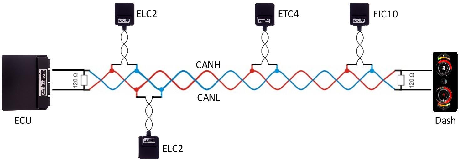
Figure 3.1 — CAN Bus wiring example: ECU and a device at each end with 120 Ohm termination.
4.0 ETC Device Configuration
Once the ETC4 or ETC8M is powered and connected to the ECU’s CAN bus, the following steps should be taken to complete the setup. All setup and device monitoring is done using Emtune, so this software needs to be installed and connected to the ECU.
NoteNOTE When a Thermocouple Input has been detected as Open Circuit, the Fault Value of -50.0°C will be transmitted over the CAN Bus.
4.1 ETC Single Device Setup
This involves 3 steps: Device Detection by the ECU, ECU CAN Bus configuration, and ETC Live Data Monitoring.
4.11 ETC Device Detection — To confirm the ETC device has been detected, connect to the ECU using Emtune. Open the ECU Runtime menu (F3) and select the Communications Tab. This lists the CAN Device Model, Device Serial Number, Device Firmware Version, Device Hardware Version, and CAN Base Address ID for each detected Emtron CAN device. At this stage the ECU has only detected the device — it has not yet been configured to an ECU CAN Channel. Note the CAN Base Address ID (factory setting is 691 for the ETC4, 700 for the ETC8M).
4.12 ECU CAN Configuration for Single Device — Configure an ECU CAN channel to allow the ECU to decode the ETC CAN packets (e.g. CAN 1 – Channel 3):
- Set “Enable” to 1 (ON).
- Set “CAN Base Address” to the Base Address shown in the runtime (691 for ETC4, 700 for ETC8M).
- Set “DATA Set” to 60 (ETC4 1× Device) or 65 (ETC8M 1× Device).
4.13 ETC Data Monitoring for Single Device — To confirm the ETC data is being decoded by the ECU, open the runtime menu (F3) → Emtron CAN Device Tab. The ETC4/ETC8M EGT and Cold Junction Temperatures live data can be viewed.
4.2 ETC Multiple Device Setup
The Base CAN Address ID used to transmit data over the Bus is the same for each device type by default. When multiple ETC4/ETC8M devices are installed on the same CAN Bus, each device MUST have a unique CAN Base Address to avoid Bus conflicts. The CAN Base Address ID is reprogrammed using the ID Reprogramming Tool (section 4.22).
NoteREMEMBER When multiple new devices are introduced to the CAN bus, they should initially be connected one at a time so each device can sync to the CAN Bus baud rate and store that setting (3-5 seconds).
4.21 Multiple Device Detection — With multiple devices connected, the CAN Summary List (F3 → Communications Tab) shows each device. By default all share the same Base Address (691 for ETC4). To avoid Bus conflicts, when re-programming the Base Address for each device the IDs MUST be: (1) sequential in order, (2) have a gap of 1 number between each ETC4 device, (3) have a gap of 2 numbers between each ETC8M device. Recommended:
- ETC4 Device 1/2/3: ID Base Address 691 / 692 / 693
- ETC8M Device 1/2: ID Base Address 700 (range 700–701) / 702 (range 702–703)
4.22 CAN Base Address ID Reprogramming — In Emtune go to Config View → Communications → Emtron CAN Devices → Emtron CAN Device Programming. Enter the device Serial Number and the Custom Address, tick “Program Address”, then select “Program”. Repeat for each device. Confirm via F3 → Communications Tab that each device now has a unique Base Address ID.
4.23 ECU CAN Configuration for Multiple Devices — Only 1 CAN Channel is required for multiple devices (e.g. CAN 1 – Channel 3):
- Set “Enable” to 1 (ON).
- Set “CAN Base Address” to the lowest Base Address ID (e.g. 691).
- Set “DATA Set” to 62 (Emtron ETC4 3× Devices, CAN PID 691/692/693). Use option 61 for 2× ETC4 devices.
You only need to program in the lowest Base Address — the ECU automatically configures the remaining IDs based on the assumption the IDs are sequential.
4.24 Data Monitoring for Multiple Devices — Confirm via the runtime menu (F3) → Emtron CAN Device Tab.
5.0 ECU Channel Configuration
Once the ECU has been configured to receive the ETC data, the next step is assigning the data to ECU channel(s). Select Config View → Channels → Inputs Setup → EGT Tab. Select “Exhaust Gas Temp Cyl 1” and open the Input Setup menu:
- Set Input Source = CAN ETC4 #1 Ch-1
- Filter = 0 (normally not required as filtering is done by the ETC device)
- Calibration Type = Predefined
- Predefined Calibration = CAN – EGT 1:1 Scaling, or ETC8M/ETC4 1:1 Scaling
NoteNOTE The CAN values can be scaled using the 2D calibration if required by setting the Calibration Type to “Custom”. Repeat the process for the remaining channels.
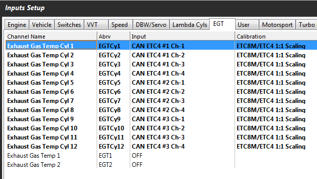
Figure 5.1 — ECU EGT input channels assigned to ETC4 CAN data.
6.0 ETC Custom Device Setting
The EGT data Transmit rate is adjustable on the ETC4 and ETC8M: 200Hz (Default), 50Hz, 100Hz, 500Hz. Configure using Emtune from Config View → Communications → CAN Device → Emtron Thermocouple to CAN Setup. Adjust to suit the application and available CAN bandwidth.
NoteNOTE Once changed, the setting is automatically stored by the ETC device and used on the next power cycle.
7.0 Ordering Information
| Product | Part Number |
|---|---|
| Emtron ETC4 | 5203-4 |
| Emtron ETC8M | 5203-813 |
Appendix 1 — CAN Bus Data Packaging (Device FW 36 or Later)
This section provides detailed information on the CAN ID data structure and requires an understanding of both CAN protocols and data packaging. If the device is connected to an Emtron ECU, the CAN Bus packet is automatically decoded when the correct CAN Dataset is selected and no additional setup is required.
ETC4 CAN Data Format — ID 691 / 0x2B3 (Default), Standard 11-bit identifier, Transmit from Device, Length 7 bytes, Tx Rate adjustable (50/100/200/500 Hz).
| Name | Start bit | Length (bits) | Byte Order | Data Type | Multiplier | Offset | Units | Example |
|---|---|---|---|---|---|---|---|---|
| EGT Channel 1 | 0 | 12 | Big Endian | Unsigned | 1 | -50 | DegC | CAN 900 = 850 DegC |
| EGT Channel 2 | 12 | 12 | Big Endian | Unsigned | 1 | -50 | DegC | |
| EGT Channel 3 | 24 | 12 | Big Endian | Unsigned | 1 | -50 | DegC | |
| EGT Channel 4 | 36 | 12 | Big Endian | Unsigned | 1 | -50 | DegC | |
| Cold Junc. Temp | 48 | 8 | NA | Unsigned | 1 | -50 | DegC | CAN 68 = 18 DegC |
ETC8M CAN Data Format — ID 700 / 0x2BC (channels 1-4 + cold junction) and ID 701 / 0x2BD (channels 5-8 + open-circuit status), Standard 11-bit identifier, Transmit from Device, Length 7 bytes.
ID 700 carries EGT Channels 1-4 (start bits 0/12/24/36, 12 bits each, Big Endian, ×1, offset -50, DegC) plus Cold Junc. Temp (start bit 48, 8 bits, ×1, offset -50).
ID 701 carries EGT Channels 5-8 (start bits 0/12/24/36, 12 bits each, Big Endian, ×1, offset -50, DegC) plus an Open-Circuit Status byte (start bit 48, 8 bits):
| Bit | Meaning | Bit | Meaning |
|---|---|---|---|
| 0 | EGT Ch 1 Open Cct | 4 | EGT Ch 5 Open Cct |
| 1 | EGT Ch 2 Open Cct | 5 | EGT Ch 6 Open Cct |
| 2 | EGT Ch 3 Open Cct | 6 | EGT Ch 7 Open Cct |
| 3 | EGT Ch 4 Open Cct | 7 | EGT Ch 8 Open Cct |
Appendix 2 — CAN Bus Data Packaging (Device FW 35 or earlier)
The packet structure is identical to Appendix 1, except that EGT Channels 1 and 3 use Little Endian byte order (Channels 2 and 4 remain Big Endian). This applies to both the ETC4 (ID 691) and ETC8M (IDs 700 and 701). All multipliers, offsets (-50), units (DegC) and the Open-Circuit Status bit mapping are unchanged.