Drive By Wire Throttle Position
Emtron Drive By Wire (DBW) control is more than a simple DC position control system. DBW can be leveraged for many purposes beyond opening and closing relative to a pedal target. Understanding how the Emtron strategy works is important to getting the most from it.
Pedal Demand
Users often try to quantify the relationship between pedal position and servo position — but this is not a 1:1 relationship.
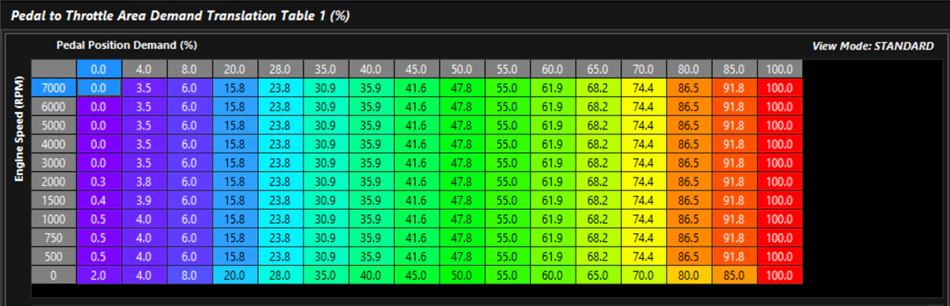
The Driver Demand Torque tables in the Torque Management section contain the Pedal to Throttle Area Demand translation tables. These allow the user to shape demand into the model. While this may appear to be a traditional translation to servo position, it is actually a translation to Throttle Area — a function of the Throttle Body Model.
Screenshot 1a: Pedal Demand Screenshot 1b: Pedal Demand Table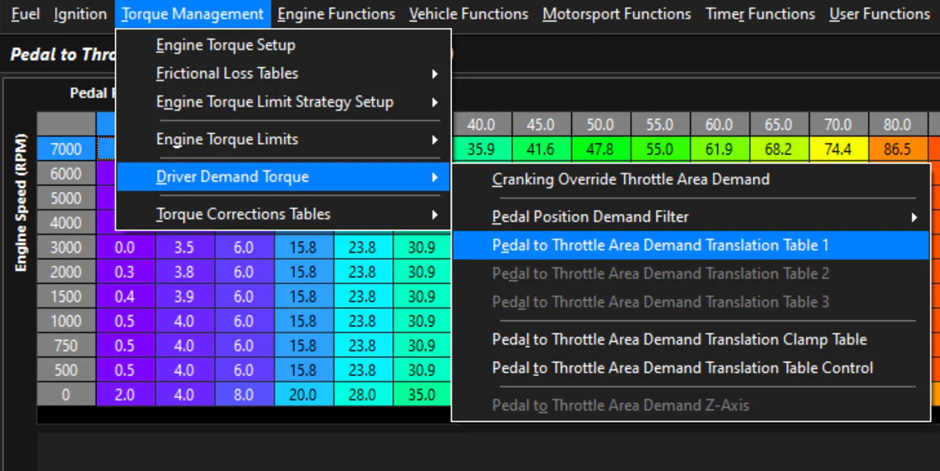
Throttle Body Model
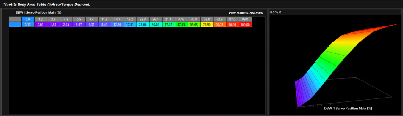
In Engine Functions > Throttle Body Model, the Throttle Body Area table defines what the Pedal to Throttle Area Demand translates to. This is the only place where direct demand to raw servo position target can be quantified.
In most cases, a calibrated Throttle Area will not be 1:1 with position (0–100% or degrees). Simply holding a throttle body and observing the visual area as it opens makes this obvious. Mechanical throttles historically used linkage mechanisms to shape the pedal/cable input relative to throttle blade movement — particularly on engines with large throttles or carburettors with primary/secondary barrel ramps.
The common first instinct is to target DBW like a cable throttle (1:1), but as noted above, most cable throttle setups are not truly 1:1 either. In a traditional Pedal-to-Servo PID controller system, calibrators typically end up with a “bent” demand table to make the car drivable — which is actually an inverse representation of the throttle body’s true area curve.
Screenshot 2a: Throttle Body Model Setup Screenshot 2b: Throttle Body Area Table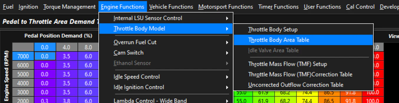
Throttle Body Area vs DBW Servo Position
The Emtron Throttle Body Model generates airflow through the model with the correct sensors fitted. It also calculates engine torque through a complex torque model — not a simple estimation system. These can be used to validate throttle area against a true value. The screenshots above show the Throttle Position (raw servo position) channel compared to the Throttle Effective Area channel on a calibrated throttle.
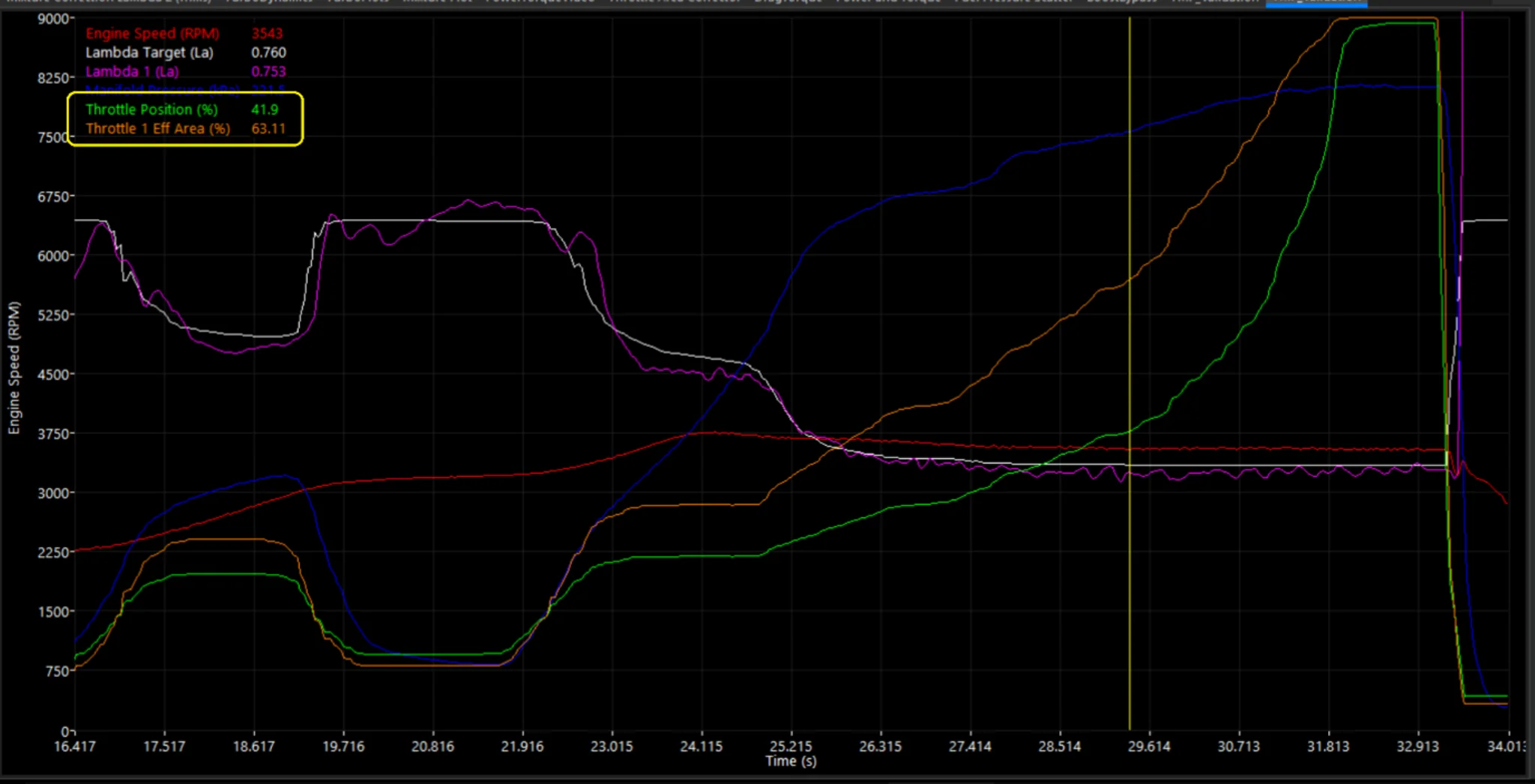
Screenshot 3: Throttle Body Area vs DBW Servo Position
Returning to the 1:1 instinct — this is achieved by targeting Throttle Area Demand 1:1, not raw servo position (demand is mostly linear, as seen in Section 1).
The additional benefit of the calibrated system is that at varying engine loads, pressure ratios, and conditions, the throttle area demand for Torque Management can be reverse-calculated to control engine torque output. This is superior to simply closing raw servo position, which is not compensated by actual engine load, airflow, or other factors.