Technical Articles
A collection of technical articles
A collection of technical articles
Knock (detonation) is one of the biggest killers of a performance engine. Emtron ECUs monitor individual cylinder knock and make cylinder-specific ignition adjustments to keep the engine safe without unnecessarily impacting performance through a global ignition trim.
The log below is taken from a mildly tuned EVO IX engine:
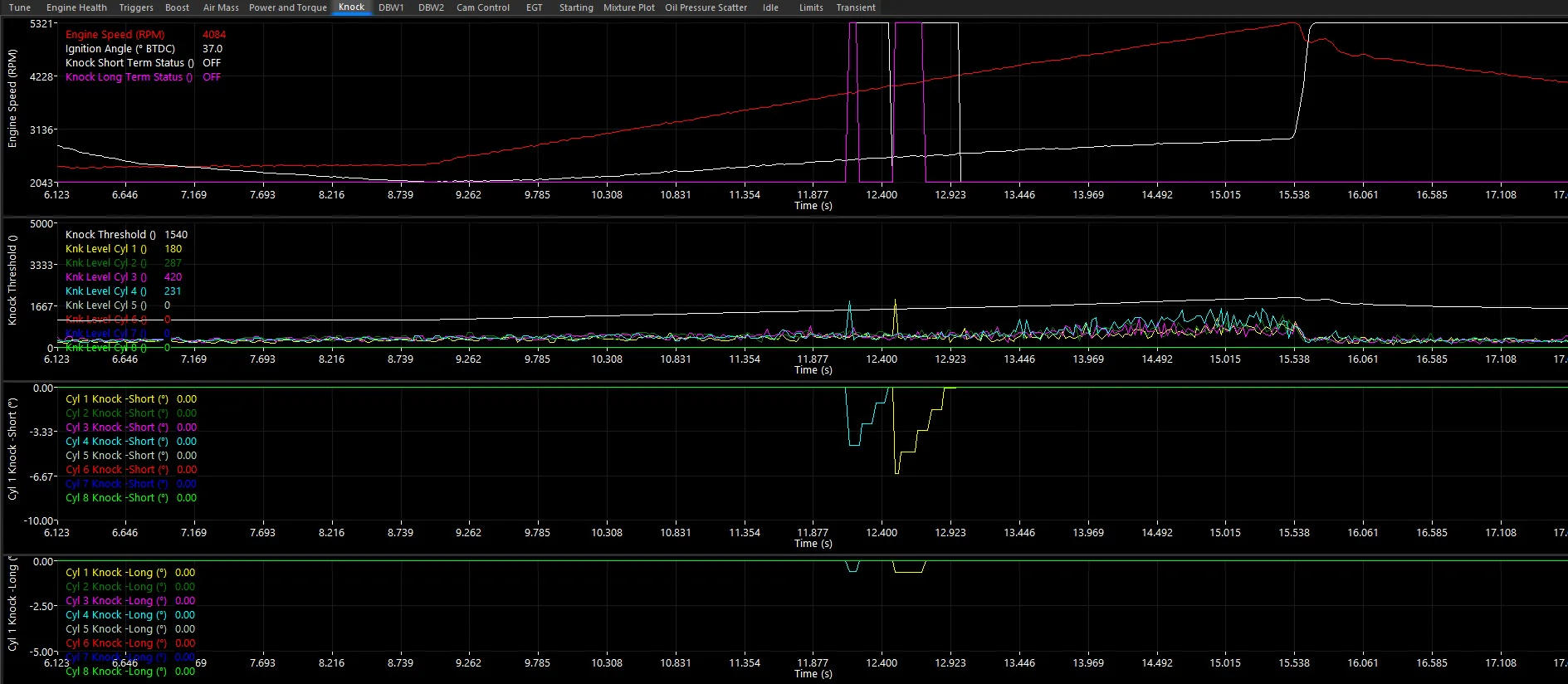
Knock Control Log – EVO IX
In this example, Knock Level Cyl 1 and Knock Level Cyl 2 each show a knock event where the level exceeded the knock threshold. The ECU detected the knock and pulled 6.5° from Cylinder 1 and 4.4° from Cylinder 4 via short-term retard. The long-term retard also reduced timing advance by a moderate amount.
This data allows each cylinder to be individually trimmed with ignition or fuel adjustments to optimise power and manage knock events. If knock does occur, the ECU will retard timing automatically — provided the system is correctly configured.
Emtron Drive By Wire (DBW) control is more than a simple DC position control system. DBW can be leveraged for many purposes beyond opening and closing relative to a pedal target. Understanding how the Emtron strategy works is important to getting the most from it.
Users often try to quantify the relationship between pedal position and servo position — but this is not a 1:1 relationship.
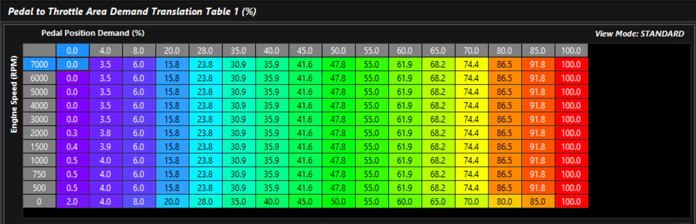
The Driver Demand Torque tables in the Torque Management section contain the Pedal to Throttle Area Demand translation tables. These allow the user to shape demand into the model. While this may appear to be a traditional translation to servo position, it is actually a translation to Throttle Area — a function of the Throttle Body Model.
Screenshot 1a: Pedal Demand Screenshot 1b: Pedal Demand Table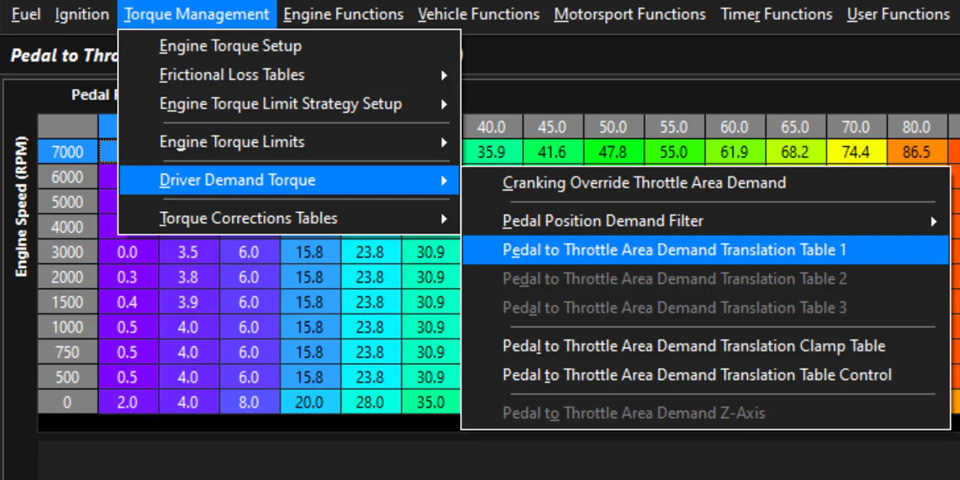
In Engine Functions > Throttle Body Model, the Throttle Body Area table defines what the Pedal to Throttle Area Demand translates to. This is the only place where direct demand to raw servo position target can be quantified.
In most cases, a calibrated Throttle Area will not be 1:1 with position (0–100% or degrees). Simply holding a throttle body and observing the visual area as it opens makes this obvious. Mechanical throttles historically used linkage mechanisms to shape the pedal/cable input relative to throttle blade movement — particularly on engines with large throttles or carburettors with primary/secondary barrel ramps.
The common first instinct is to target DBW like a cable throttle (1:1), but as noted above, most cable throttle setups are not truly 1:1 either. In a traditional Pedal-to-Servo PID controller system, calibrators typically end up with a “bent” demand table to make the car drivable — which is actually an inverse representation of the throttle body’s true area curve.
Screenshot 2a: Throttle Body Model Setup Screenshot 2b: Throttle Body Area Table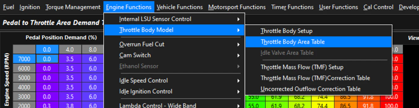
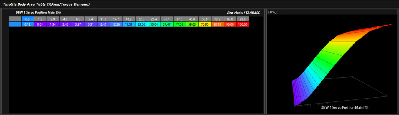
The Emtron Throttle Body Model generates airflow through the model with the correct sensors fitted. It also calculates engine torque through a complex torque model — not a simple estimation system. These can be used to validate throttle area against a true value. The screenshots above show the Throttle Position (raw servo position) channel compared to the Throttle Effective Area channel on a calibrated throttle.
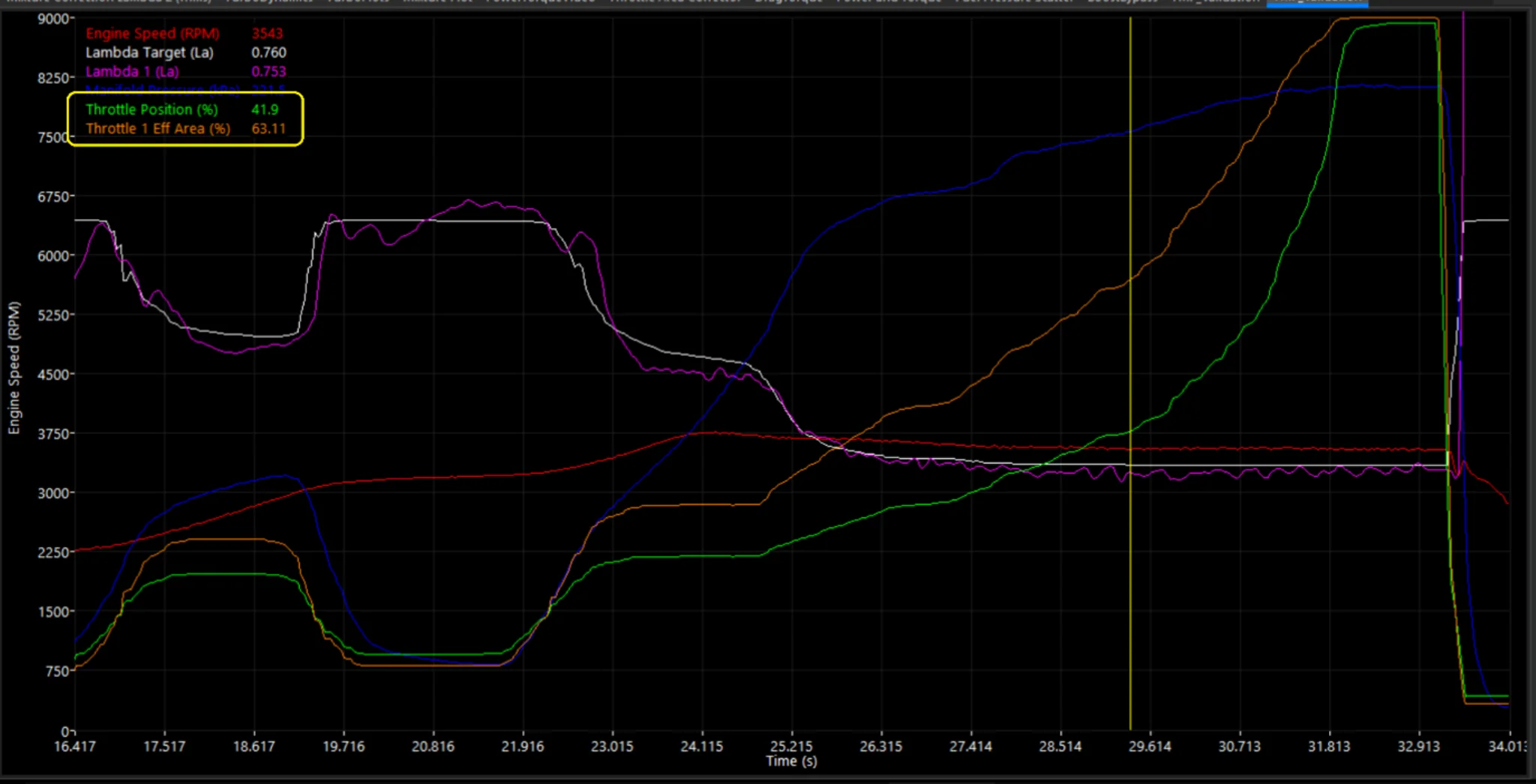
Screenshot 3: Throttle Body Area vs DBW Servo Position
Returning to the 1:1 instinct — this is achieved by targeting Throttle Area Demand 1:1, not raw servo position (demand is mostly linear, as seen in Section 1).
The additional benefit of the calibrated system is that at varying engine loads, pressure ratios, and conditions, the throttle area demand for Torque Management can be reverse-calculated to control engine torque output. This is superior to simply closing raw servo position, which is not compensated by actual engine load, airflow, or other factors.
Emtron torque modelling relies on a series of inputs and calculations to achieve accurate output estimates. Frictional loss is a significant factor when estimating engine torque output. If incorrectly calibrated, torque-based functions will not perform as designed and may perform worse than equivalent legacy functions. The ECU provides three frictional loss tables for calibration, as shown in Screenshot 1.
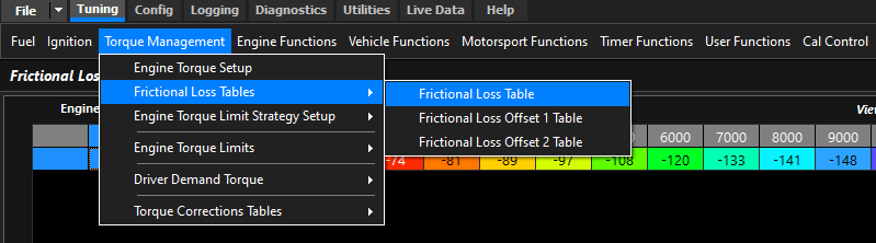
Screenshot 1: Frictional Loss Tables
The Frictional Loss Table is the primary table that must be set. The default values in any Emtron base file will generally be a reasonable starting point, but the better this is calibrated the better torque-based functions will perform. Screenshot 2 shows an example table from a Nissan RB26 six-cylinder engine. As a general rule, higher cylinder counts produce higher frictional losses. Modern engines almost always have significantly lower frictional loss than older counterparts.
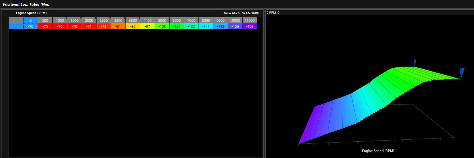
Screenshot 2: Frictional Loss Table (Nm)
Oil temperature also influences frictional loss — cold oil increases friction. The Frictional Loss Offset 1 Table is calibrated against engine oil temperature, as shown in Screenshot 3. The table is normalised to zero near the target operating oil temperature (90°C in this example). The Frictional Loss Offset 2 Table is available for additional calibration inputs and can be set to zero for most applications.
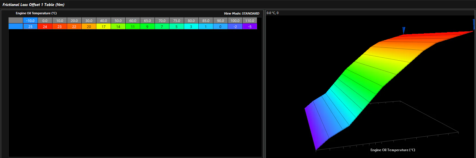
Screenshot 3: Frictional Loss Offset 1 Table (Nm)
Engine mapping must be completed correctly before calibrating the frictional loss tables. Calibration should be performed at the target engine oil temperature.
Main Frictional Loss Table:
Engine speed step-and-hold testing can yield even more accurate readings but is not necessary for most applications.
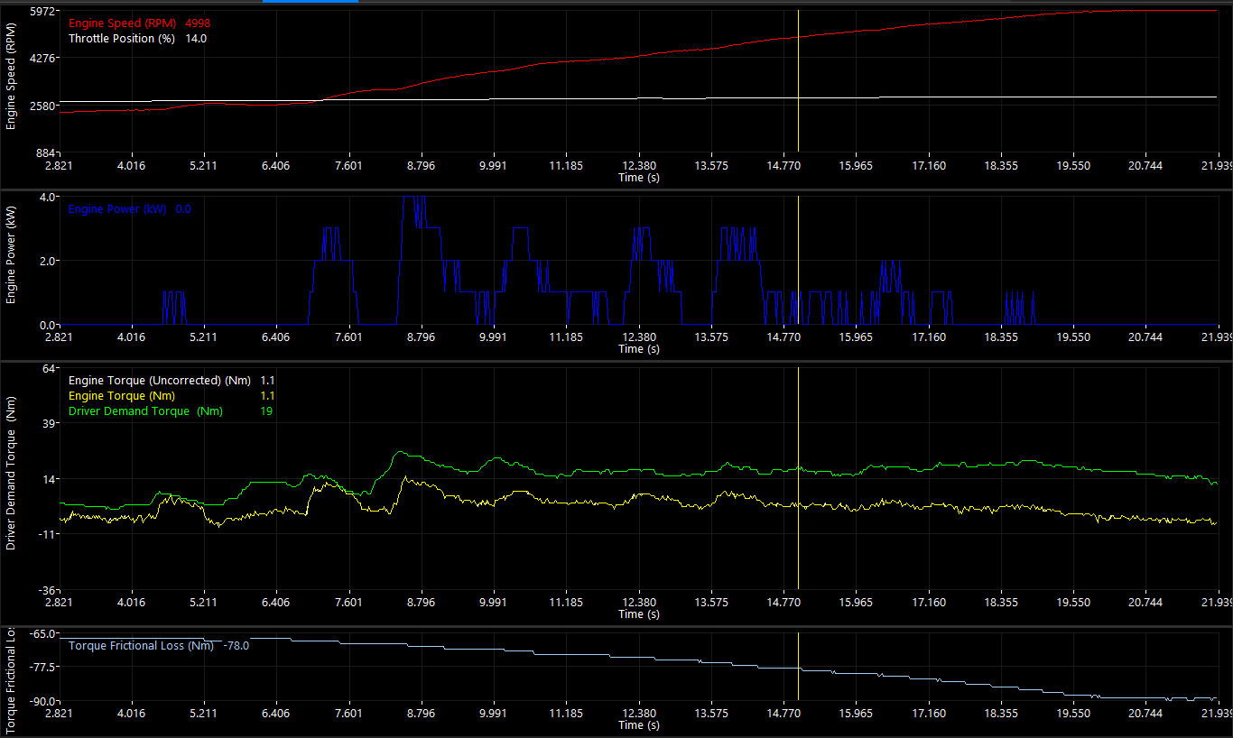
Screenshot 4: Example Engine Speed Sweep
Frictional Loss Offset 1 Table (cold oil):
These tables should not require further adjustment unless engine changes affect frictional characteristics.
For idle speed control, users often try to manage engine speed by manipulating throttle position to control airflow. This works reasonably well with solenoid systems (ICV), where position has a more proportional effect on airflow.
With DBW — especially on larger throttles — small changes in throttle position have a disproportionately large effect on airflow, making fine control difficult. Emtron addresses this with a purpose-built approach.
TMF (Throttle Mass Flow) Idle Speed Control is a specialised function that provides superior airflow control at idle by working directly in mass flow terms rather than raw position.
The concept is straightforward: the airflow required to idle the engine is mapped and controlled directly. The Initial Position table defines target airflow (g/s) based on XY parameters.
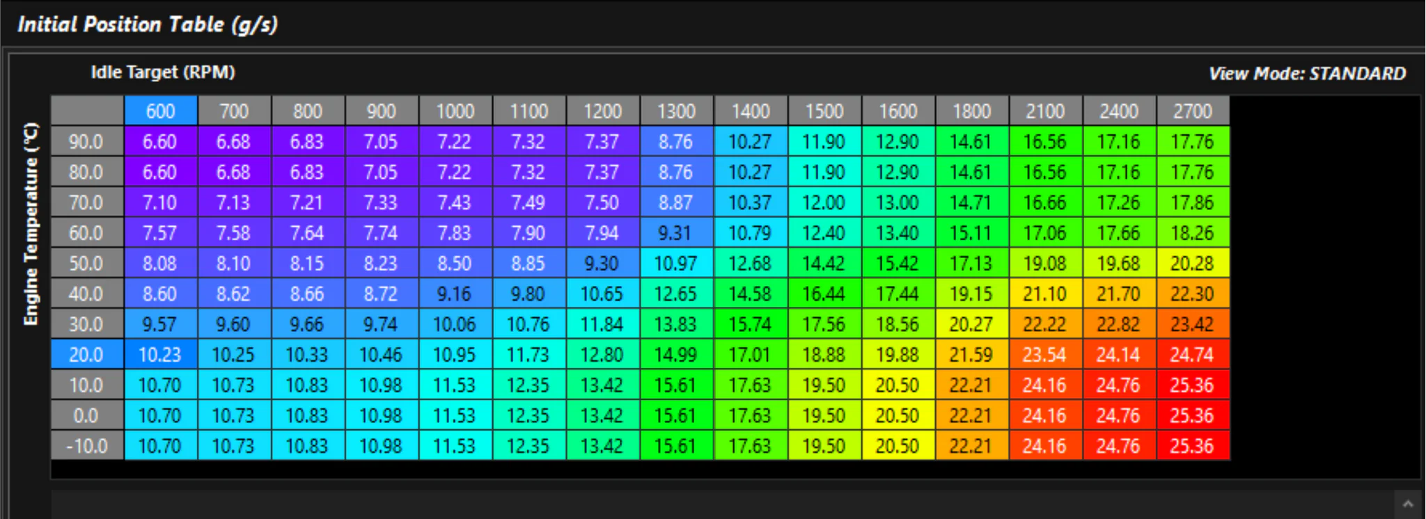
Screenshot 1: Initial Position (g/s) – Airflow-based idle target table
A PID loop can be enabled for adaptation, just as with traditional idle systems. Because the PID output is airflow rather than raw position, it has greater authority and precision.
The target air mass is translated to a DBW servo position via the Throttle Body Model, which should be validated before relying on TMF idle control.
Screenshot 2a: Throttle Body Model Setup Screenshot 2b: Throttle Body Area Table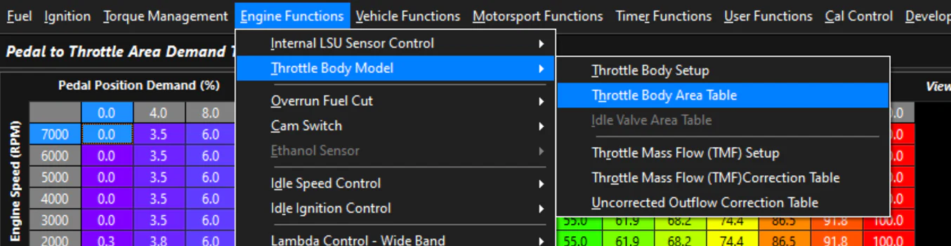
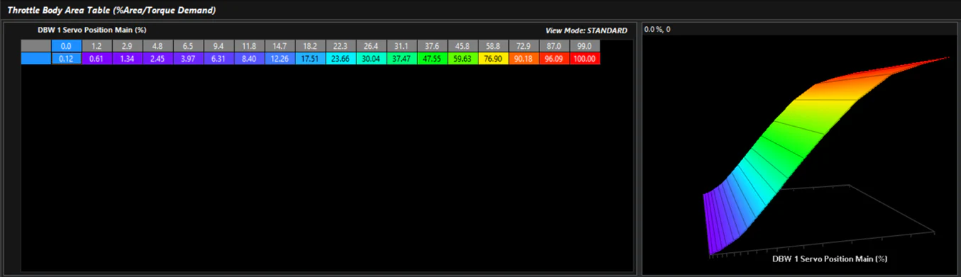
Regardless of whether the Throttle Body Model is used as part of the engine’s airflow model, TMF Idle Speed Control uses the TMF calculation to determine DBW position.
TMF Idle Speed Control should be treated as the base air delivery system. Idle Ignition Control handles fine idle speed corrections, as ignition timing has a fast and predictable effect on engine torque at low RPM.
Screenshot 3: TMF Idle with Idle Ignition Control Screenshot 4: Example Base Idle Initial Position (airflow) and corresponding Base Idle Ignition Table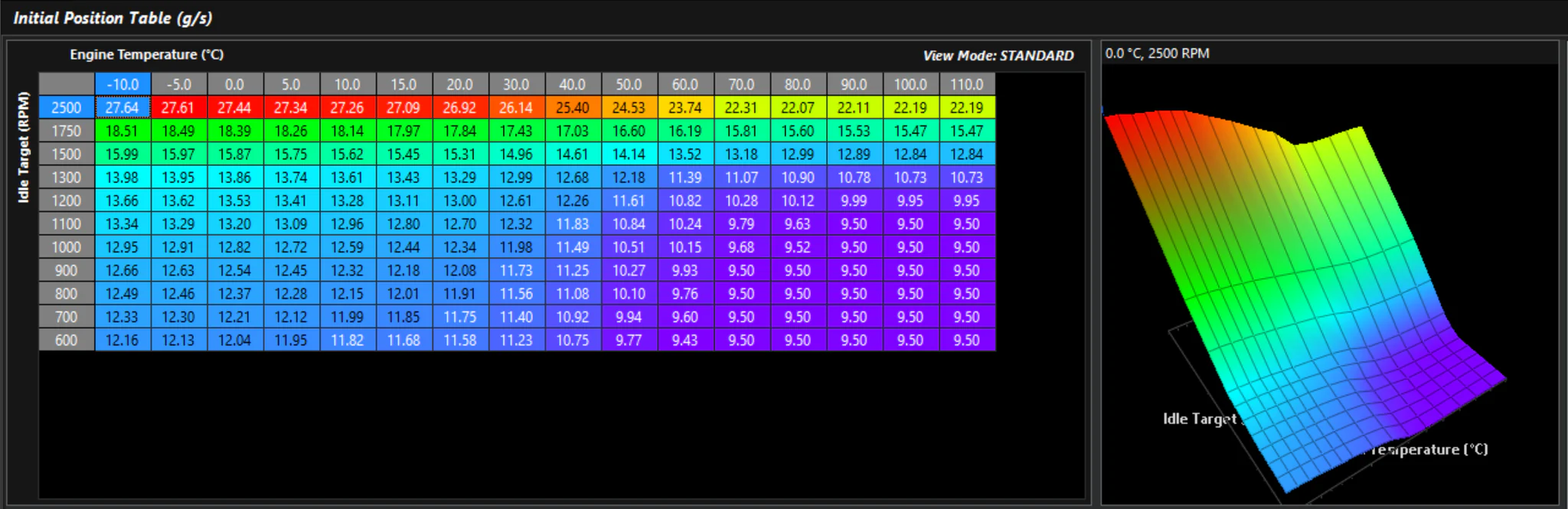
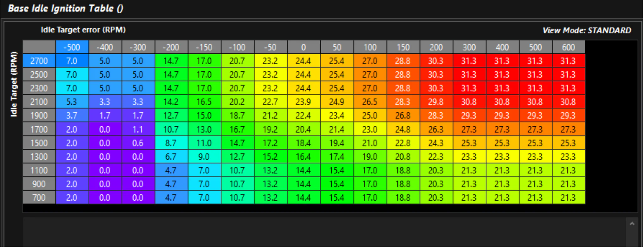
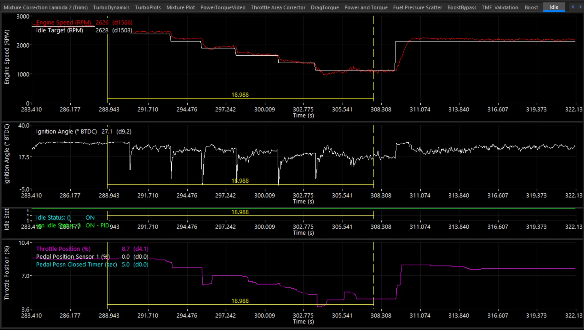
The Emtron Idle Ignition Control is a comprehensive system with full PID controls. When used together with TMF Idle Speed Control, it delivers OEM-level idle quality on virtually any application.
Screenshot 5: Idle target adjusted live – engine following correctly Screenshot 6: Log showing throttle position and ignition control working together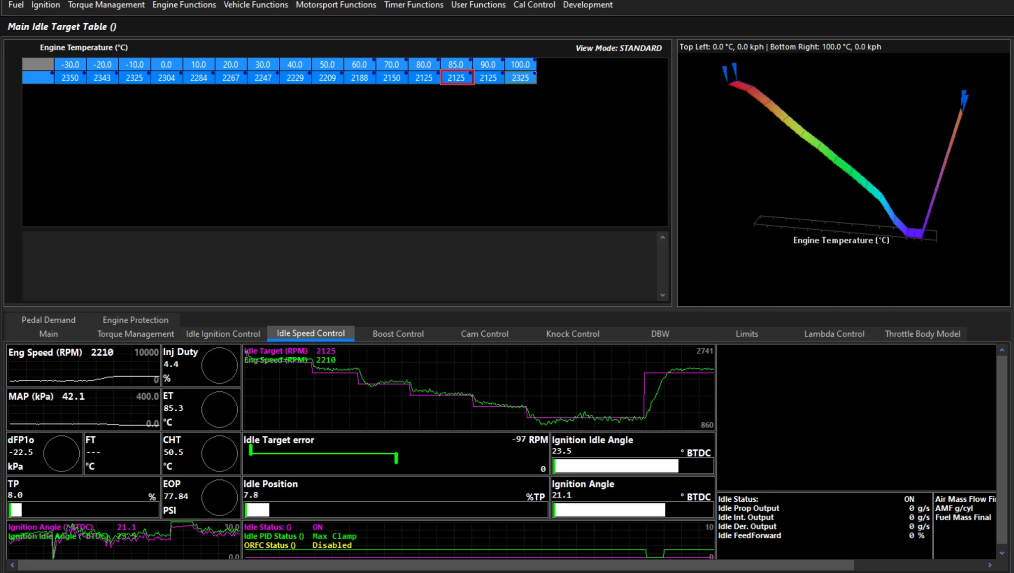
The V2.19.0 firmware release in EMtune introduced a major expansion of the ECU’s engine output control capabilities. While Emtron ECUs have had torque control for several years, it was previously only available within specific dedicated functions or OEM application builds — limiting flexibility for custom and motorsport applications.
The new User Torque Limits section changes this. There are now five fully user-configurable torque limits that can be assigned to any purpose. As shown in Screenshot 1, each limit is enabled and labelled independently.
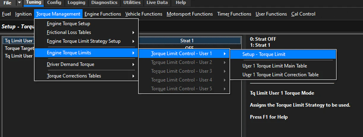
Screenshot 1: Torque Limit Control – User 1
Screenshot 2 shows the main setup screen, where you configure:
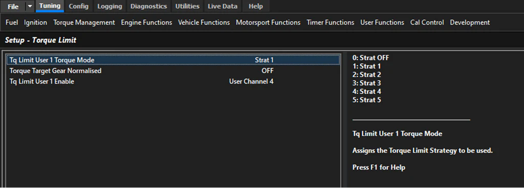
Screenshot 2: Torque Limit Setup
Once setup is complete, a 16×12 cell table defines the desired torque target based on nearly any ECU channel. A Torque Limit Correction table is also available to adjust this target by a set percentage. When the assigned User Output channel activates, the ECU monitors engine torque output and applies the configured strategy to meet the limit.
Screenshot 3 shows a log from a high-performance turbocharged four-cylinder Time Attack engine. The Strat mode uses a combination of throttle reduction and ignition retard to achieve a 600 Nm torque limit.
In this example the strategy heavily favours throttle control, so the margin between corrected and uncorrected torque is small — the throttle is handling most of the airflow reduction, with ignition retard making up the balance to hit 600 Nm. The ECU continuously adjusts both throttle area demand and ignition angle, resulting in an extremely smooth 600 Nm output.
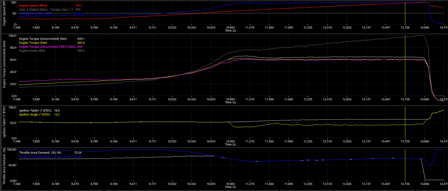
Screenshot 3: Example Logging Data – 600 Nm torque limit active
For more detail on the available strategy types, see the Torque Limit Strategies article.
When announcing new firmware functions, we discussed the addition of the User Engine Torque Limits function and how Strategy (Strat) modes control how the ECU limits torque output. Screenshot 1 shows where the Torque Limit Strategies are configured. There are five Strat modes available. At the time of writing, the functions that can be linked to these strategies are: Traction Control (Torque Mode), Launch Control (Torque Mode – Static), Launch Control (Torque Mode – Moving), and User Torque Limits. Using the same 600Nm example from our last post, we will look at the Strat mode used to achieve that target.
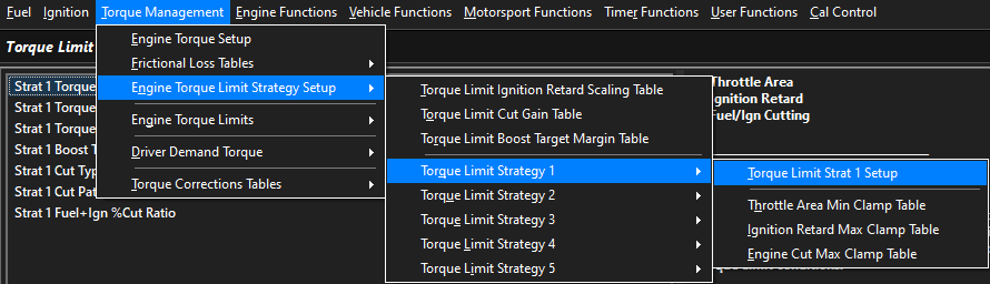
Screenshot 1: Engine Torque Limit Strategy Setup – Torque Limit Strat 1 Setup
Screenshot 2 shows the Torque Limit Strat 1 Setup, which is the core configuration dictating how the ECU reduces engine torque. There are three limit priorities, and the ECU works through them in order — Priority 1, then Priority 2, then Priority 3 — until the Torque Target is met. As seen in Screenshot 1, each torque limiting method has an associated clamp table that controls how much the ECU can use that method before moving to the next priority.
In this example, only Priority 1 (Throttle Area) and Priority 2 (Ignition Retard) are used. When a torque limit is requested, the ECU calculates the required throttle reduction using Throttle Mass Flow calculations, then monitors the Throttle Area Min Clamp Table. If the Torque Target is reached before hitting the clamp limit, only Priority 1 is needed. If engine torque remains above the target, the ECU moves to Priority 2 (Ignition Retard) to make up the difference. Provided the Ignition Retard Max Clamp Table allows sufficient retard, the target will be met. If not, the ECU falls through to Priority 3 — set to OFF in this example — making it essential that the Priority 1 and 2 clamps together allow enough torque reduction to reach the target.
Cutting (fuel, ignition, or both) is not used here but is a highly effective torque reduction method. Note that the Engine Torque channel is derived from Air Mass Final in the ECU. Any discrepancy between the Throttle Mass Flow calculated value and Air Mass Final will affect torque reduction accuracy. When throttle reduction is the primary method, it is recommended that Air Mass Final uses a strong blend of Throttle Mass Flow Calculated to minimise errors.
The ECU can also leverage fuel cut, ignition cut, or a combination of both. Cutting provides fast, near-instantaneous torque reduction, typically used for short durations. Further examples will be covered in future posts.
Boost Target Override is another Strat Mode feature that allows the ECU to calculate a reduced boost target during torque reduction. While not covered in detail here, it is particularly useful when there is a large gap between airflow-generated torque and the torque target — it is impractical to produce 1000Nm of airflow torque and then request only 50Nm of output. It also helps reduce throttle closure levels during active torque limiting by reducing airflow relative to driver demand.
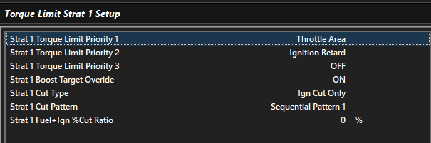
Screenshot 2: Torque Limit Strat 1 Setup