Emtron CDI8b — 8 Channel
Emtron8b — 8 Channel Capacitor Discharge Ignition (© M&W Ignitions / Emtron Australia)
WarningCAUTION This wiring diagram is applicable only to ignition systems with a serial number prefix starting 47xxxx. Use of the incorrect diagram will void warranty and may damage the unit.
The installation of high energy ignition systems may require advanced knowledge and skills. Improper installation or operation of this unit could cause damage to the ignition system and ignition coil.
Installation Notes
Mounting
Do not mount the unit where it will be exposed to water or other liquids; ensure the bottom condensation slots are unobstructed and oriented to permit gravity drain. Select a location away from intense heat and, if required, provide a source of cooling air to remove internally generated heat.
WarningWARNING Failure to use the supplied rubber mounts will void warranty! Suitable replacement anti-vibration mounts are M&W #MNT002, or Paulstra Radiaflex #521128.
Ignition Leads
Do not use plain metal wire or carbon core ignition leads. Use spiral wound inductively suppressed metal core ignition leads such as those available from Magnecor (www.magnecor.com).
Spark Plugs
The use of non-resistor spark plugs (where possible) will greatly enhance ignition performance. In some installations the use of resistor spark plugs may be unavoidable. In these cases ensure they are not damaged by testing the internal resistance value as part of regular maintenance. Open circuit or high resistance may cause failure of spark plug wires, ignition coils and the CDI.
Surface discharge and semi-surface discharge spark plugs are designed for use with CDI ignition; however, be aware they have a large non-adjustable spark gap suitable only for naturally aspirated or low boost applications.
Insulation Precautions
Degrease spark plug insulators and coil/plug boots after handling to prevent tracking or insulation breakdown. Use the supplied dielectric grease on spark plug insulators and coil/plug boots to increase insulation properties and ease installation/removal. Use of dielectric grease in the main connector may reduce water ingress.
Wiring & Power Supply
EMtron CDI systems are designed to blow the external fuse under conditions of over voltage or reverse polarity. Faults such as loose battery terminals, poor wiring or a defective alternator/regulator may also cause this to occur. Fitting a larger capacity fuse won’t disable this feature, will void warranty and may cause irreparable damage to the unit. Only fit the recommended size fuse!
Main connector pins are designed to be roll crimped. Squeeze crimping or soldering will cause distortion resulting in misfiring or incorrect CDI operation.
Wire the ignition system directly to the battery. If required wire length exceeds recommendations, use small paired battery cable (power and ground) to make up the distance. Do not rely on the vehicle chassis to provide a ground path. If connected to a high impedance supply shared with the ECU or its sensors, erratic operation will be experienced.
Do not use voltage boosters as most can’t provide the instantaneous current required for correct CDI operation.
When using a total loss electrical system, install either a 16V or 18V battery to ensure adequate supply voltage. If using extended voltage batteries, isolate them during charging to prevent excessive voltage reaching the CDI and ECU.
Use twisted pair wire for all power and coil connections. For improved noise suppression and to comply with Australian EMC ‘C Tick’ standards, use twisted shielded pair wire for coils. Twisted pair wire must be used for power/ground. Keep coil wires one continuous length from the CDI and do not fit any intermediate connectors into the harness. All coil negative wires must be joined at or in the CDI connector. Keep coil primary (CDI) wires away from HT leads, the coil HV outlet and the coil body to prevent a flashover occurring.
Triggering
Trigger input & coil output numbers (letters) indicate CDI ignition sequence, not cylinder number. EMtron CDI systems default to falling edge ignition. To select rising edge ignition, install a jumper wire between the ‘Trigger Edge’ and ‘Signal Ground’ pins. Where the ECU contains an inbuilt igniter it may be necessary to use rising edge ignition.
WarningWARNING If the CDI trigger edge and ECU ignition edge do not match, timing will be erratic!
When using a Hall sensor to trigger the CDI, changing the trigger edge will alter whether the system fires on the advancing or retreating target edge.
Power Level Switch
Some EMtron CDI systems are provided with an (active low) power level switch. Do not manually activate this feature or operate continuously, as this will significantly increase spark plug wear and system current draw. Activate by grounding the input through either a ‘Hobbs’ style manifold pressure switch or a programmable output from the ECU when elevated energy levels are required.
Two Spark Switch
Some EMtron CDI systems are provided with a two spark switch for part load conditions in lean burn engines. Do not manually activate this feature as it will significantly increase spark plug wear and double system current draw. Activate by grounding the input through a programmable ECU output.
Tuning
CDI systems are ’edge triggered’ and not affected by dwell settings. EMtron CDI systems may reduce combustion delay and percentage misfire requiring a reduction in ignition timing. The resulting changes in combustion characteristics may also require alterations to fuel flow. Set ECU ignition delay to zero and tune the engine as required. Always re-tune both fuel and timing curves after installing CDI ignition.
Tacho Output
The tacho output provides a 50% duty cycle square wave signal at battery supply voltage. This will work with most aftermarket digital tachos; however, earlier types and those designed for coil negative triggering may not read accurately.
LED Indicator
After applying power to the switch wire, the LED will illuminate for 1 second and extinguish. The LED will then flash briefly with each consecutive trigger event received (it may be necessary to view the LED directly on axis). A repeated double flash of the LED may indicate a possible faulty ignition coil, faulty wiring, low supply voltage or damage to the CDI.
Testing
The CDI may be tested by momentarily grounding the trigger inputs, causing the LED to flash and the corresponding ignition coil to spark. Do not conduct this test without grounded spark plugs installed!
Installation Precautions
The main cause of CDI damage is conduction of high voltage to the coil primary wiring. Care must be taken due to the propensity for HV flashovers and insulation breakdown caused by the CDI ignition’s unique characteristics. It is important to fully read and understand these instructions and have a good knowledge of automotive electrical systems before commencing installation.
Ignition Coils
(Pro-Street systems only)
Coil Selection
Most inductive ignition coils will work reasonably well with CDI systems; however, for ultimate ignition energy and efficiency use a coil specifically designed for CDI use.
COP Coils
COP (coil on plug) coils with inbuilt drivers are not suitable for use with CDI ignition. COP coils designed for inductive ignition may contain a blocking diode in the secondary winding which must be considered during wiring (see coil polarity note below). Use resistive spark plugs with all COP coils. Keep plug gap < 0.025" (0.6mm) to prevent coil damage. DO NOT use AEM pencil coils under any circumstances!
Ferrite CDI Coils
Ferrite core CDI coils provide a lightweight solution for direct fire applications and give high secondary current; however, they may not be suitable for all applications due to their extremely short arc duration. The high level of EMI emitted by these coils may also require additional shielding to prevent electrical interference with the ECU or CDI. Do not use ferrite coils in parallel wired pairs!
Coil Polarity
All diagrams are shown for CDI style coils. For correct operation with inductive ignition coils, wire the primary connections in reverse to maintain correct spark plug polarity.
WarningCAUTION Ignition coil damage may occur if operated with an excessive spark gap.
Mounting Dimensions
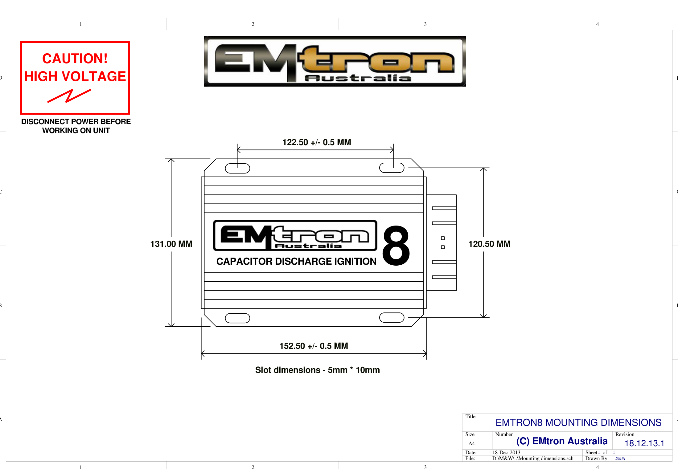
Emtron CDI8b mounting dimensions (slot dimensions 5mm × 10mm).
Connections and Specifications
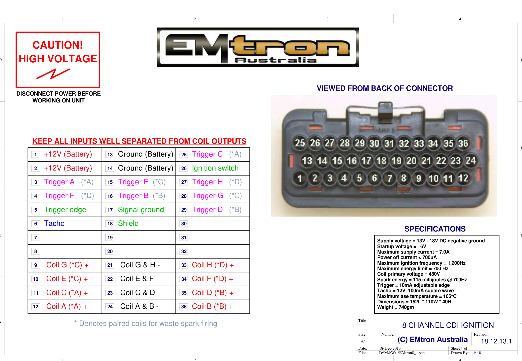
Emtron CDI8b 36-pin connector pinout (viewed from back of connector). * denotes paired coils for wasted spark firing.
Specifications
| Parameter | Value |
|---|---|
| Supply voltage | 13V - 18V DC negative ground |
| Startup voltage | +6V |
| Maximum supply current | 7.0A |
| Power off current | < 700µA |
| Maximum ignition frequency | 1,200Hz |
| Maximum energy limit | 700 Hz |
| Coil primary voltage | 480V |
| Spark energy | 115 millijoules @ 700Hz |
| Trigger | 10mA adjustable edge |
| Tacho | 12V, 100mA square wave |
| Maximum case temperature | 105°C |
| Dimensions | 152L × 110W × 40H mm |
| Weight | 740g |
8 Cylinder Direct Fire Ignition
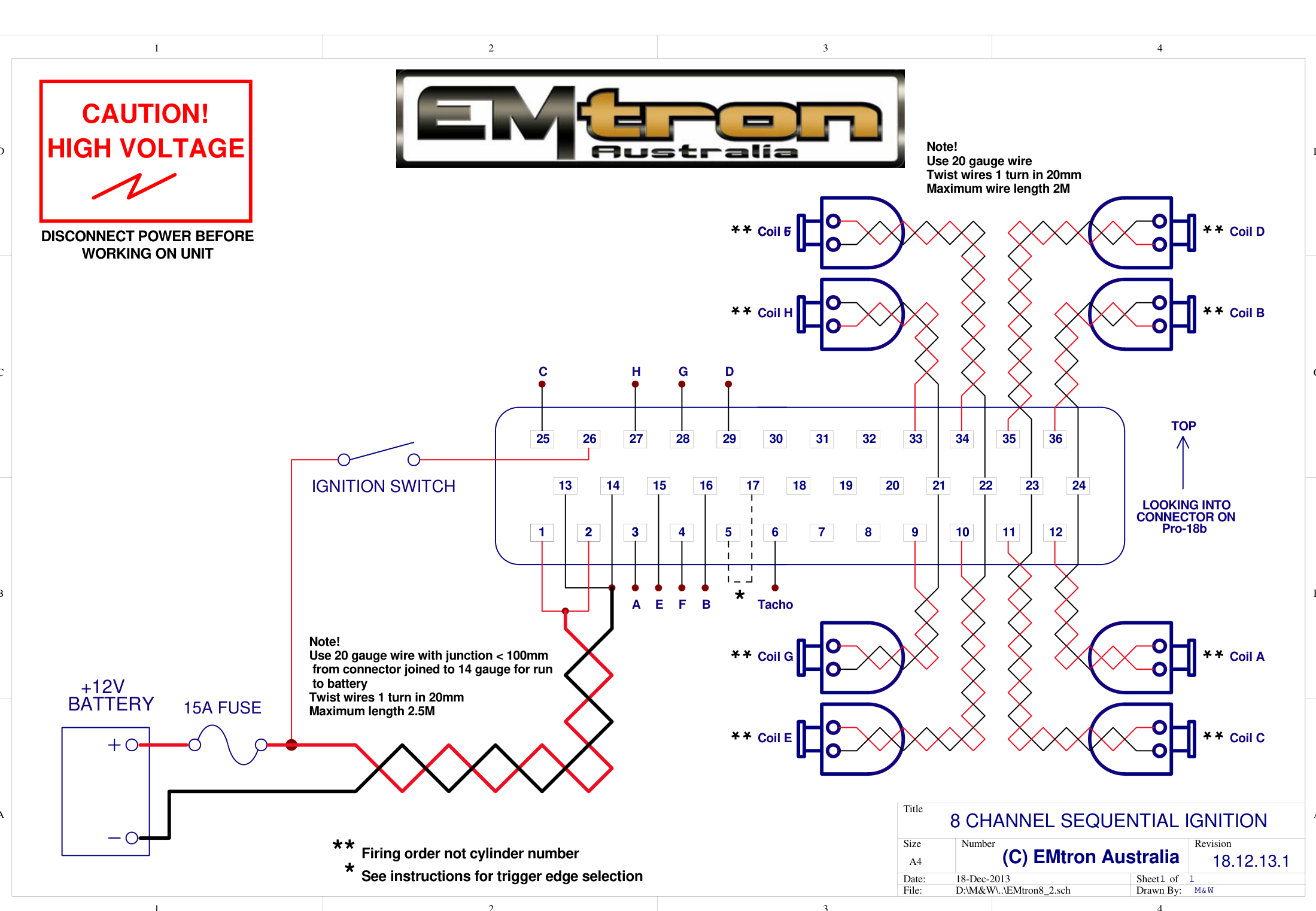
8 channel sequential ignition wiring (firing order, not cylinder number). Use 20 gauge wire twisted 1 turn in 20mm, junction < 100mm from connector joined to 14 gauge for the run to battery (max 2.5M).
8 Cylinder 8 Coil Wasted Spark Ignition
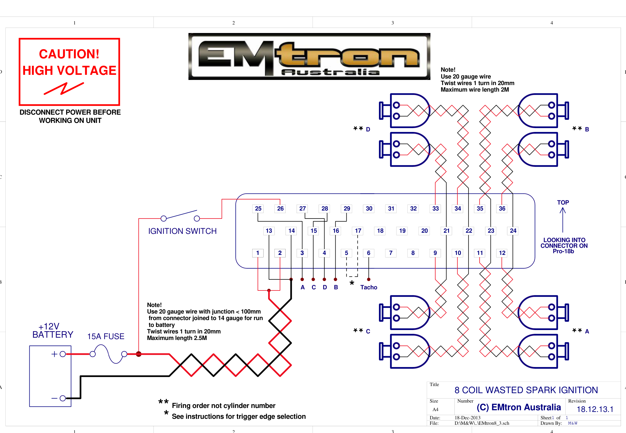
8 coil wasted spark ignition wiring. * denotes paired coils; wire by firing order, not cylinder number.
Shielding & EMC Compliance
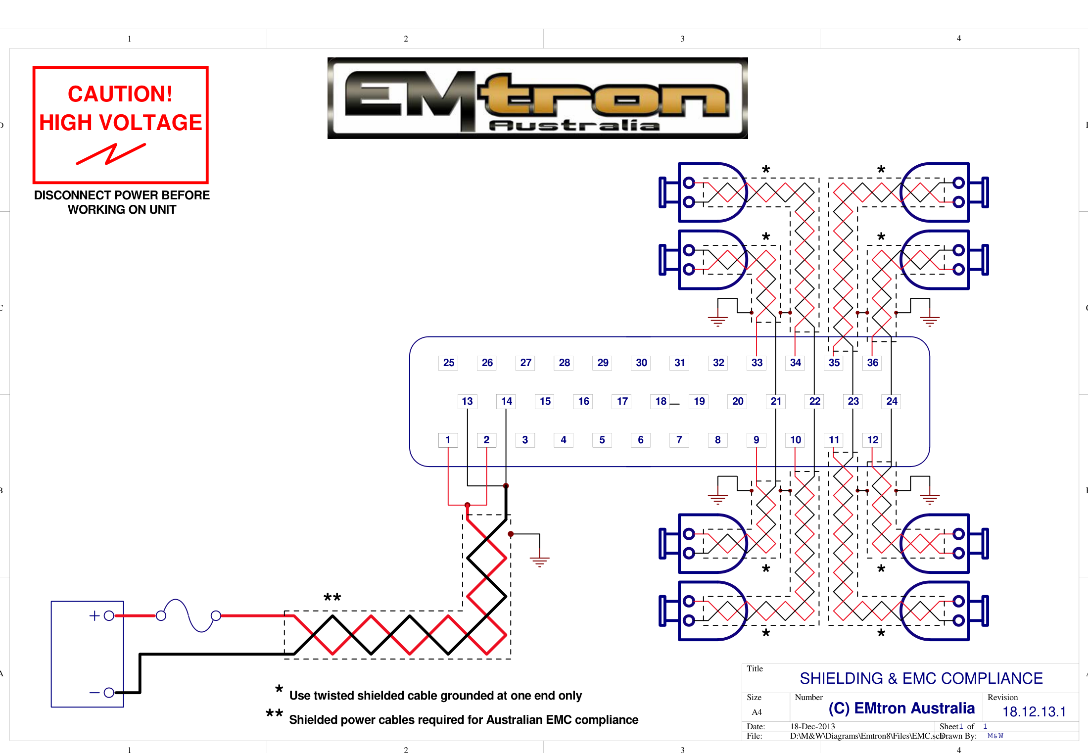
Shielding for Australian EMC compliance — shielded power cables required; use twisted shielded cable grounded at one end only.