ED7M Datasheet
1.0 General
Power Supply
- Operating voltage: 7.20V to 20.0V DC
- Operating current: 800 mA at 14.0V 50% Backlight Duty Cycle(excluding sensor and load currents)
- Reverse battery protection
Operating Temperature
- Max operating range: -30 to 85°C (-22 to 230°F)
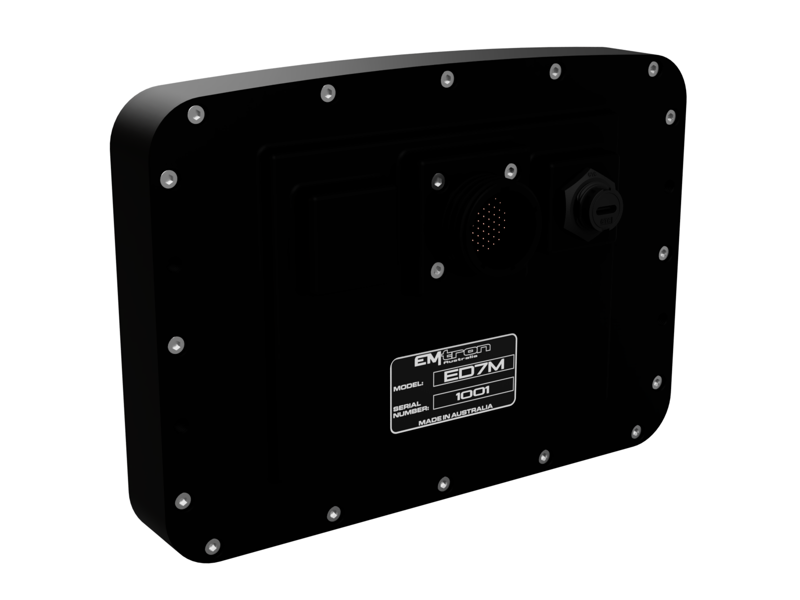
Physical
- Aluminium 6061 grade CNC billet enclosure
- Enclosure size 199 X 142mm
- Weight: 1310g
- Connector system: 55 Pin Circular Mil Spec Series III Connector
- Pin diameter: 1 mm
- Current rating: maximum 5.0A per pin at 22AWG
Internal: Specification of the SoM
- NXP® i.MX 8M Plus Quad Core
- 4 x Arm Cortex A-53
- 1 x Arm Cortex-M7 CPU 1.8GHz Core
- Arm Cortex M4 170MHz Microcontroller
- eMMC 32GB + 32GB external = 64GB total storage
- Gigabit Ethernet
- On-Board 6-axis IMU with 3-axis accelerometer and 3-axis gyroscope
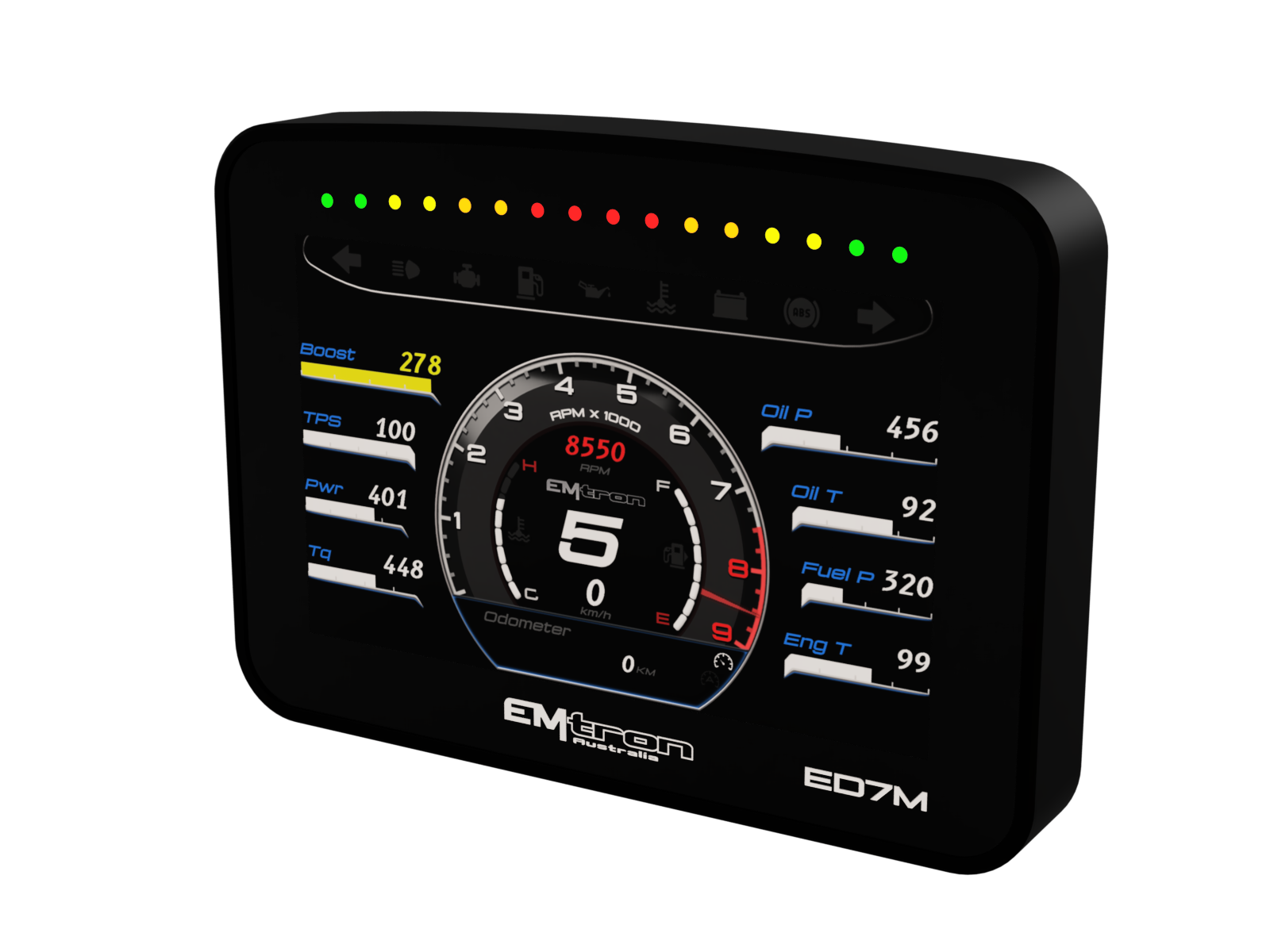
2.0 Main Features
- 7.0 inch TFT Screen – 1280 x 768 Resolution
- Anti Glare / Scratch Resistant Optical Bonded Glass
- 16x High Intensity RGB LEDs
- High Speed Gigabit Ethernet 1000Mbps
- High Speed Logging (Up to 2000Hz)
- eMMC 64GB On-board logging memory
- Real-Time clock for datalogging
- 3-axis Accelerometer and 3-axis Gyroscope
- 4x CAN Bus
- 4x Video Input
- Headphone LR Output
- Mic LR Input
- 8 x Analog External 0.0 -5.0V Inputs (see Pinout)
- Selectable CAN 120 Ohm Termination
3.0 Analog Audio
- High quality 24-bit stereo audio codec with built-in stereo headphone amplifier
- Left and Right Mic Inputs
- Left and Right Speaker Outputs
4.0 Analog Inputs
8x Analog Voltage
- Accepts a 0.0 - 5.0V Analog input. Resolution is 1.22mV (12-Bit)
- Selectable 1k Ohm pull-up resistor to 5V Sensor Supply on ANV1 – ANV4
- Selectable Range control on ANV5 – ANV8; 0.0- 5.0V or 0.0 - 15.6V
- Input Impedance 100k Ohms to ground
- Sample Rate 2000Hz
5.0 Frequency Inputs
4x Frequency Inputs
- Tolerant of inputs signals -50.0V to 50.0V
- Accepts Magnetic and Hall effect signals.
- User adjustable trigger thresholds from -10.0V to 10.0V with 0.25V built in hysteresis.
- Range 0.1Hz up to 20,000.0Hz, Resolution. 0.1Hz
- Input Impedance 100k Ohms to ground
- Selectable 4k7 Ohm pull-up resistor to 8.5V
6.0 Analog Video Inputs
- Accepts Analog baseband video signals.
- 4x Composite Inputs OR 2x S-Video Inputs
7.0 Communications
- 1x High Speed Gigabit Ethernet 1000Mbps IPv6
- Auto IP Config
- 4x CAN 2.0B
- ESD Protection
- Selectable 120 Ohm Termination Resistors
- 1 x RS232
- 1 x Lin Bus
- 1 x USB C
- 1 x Wi-Fi IEEE 802.11 ac/a/b/g/n Dual-Band (2.4/5 GHz)
- 1 x Bluetooth 5/BLE
8.0 Infield firmware update
Full In-field firmware updatable over Ethernet using the Emtron Display Setup Tool
9.0 Voltage and Ground Supplies
1x 14V Supply Input
- 5.0A Max (pin limited)
- 7.2V - 20.0V Range
- Supplies Device power
1x Backup Supply Input
- 5.0A Max (pin limited)
- 7.2V - 20.0V Range
- Supplies device power during shutdown
3x 5.0V Sensor Supply
- 5V Sensor Supply, Output current 400mA
- Accuracy: +/- 0.8% at 25 °C
- Short circuit, Reverse Battery Protection, Thermal overload protection
- Operating temperature range -40°C ~ 85°C
1x 12.0V Regulated Output
- 12V Regulated Supply, Output current 700mA
- Accuracy: +/- 1.0% at 25 °C
- Short circuit, Reverse Battery Protection, Thermal overload protection
- Operating temperature range -40°C ~ 85°C
1x Main Ground
- 5.0 A pin Limited
2x Analog Input 0V Reference
- Analog Sensor 0V Reference with short to battery protection
1x Speed 0V Reference
- Speed Sensor 0V Reference with short to battery protection
10.0 Pinout
Connector 8D0C17Z35PN: (5.0A continuous current. Shell size 17, 55 Pin. 22 AWG)
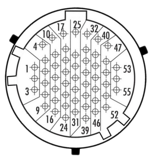
Looking into Connector
Mating Connector 8DA5-17Z35SN
| Pin | Channel Name | Pin | Channel Name |
|---|---|---|---|
| 1 | 14V Switched Supply | 29 | CAN 3 Low |
| 2 | Ground | 30 | CAN 4 High |
| 3 | Gigabit Ethernet Shield | 31 | CAN 4 Low |
| 4 | 12V Regulated Output | 32 | Analog Input Channel 5 |
| 5 | 14V Backup Supply | 33 | Analog Input Channel 6 |
| 6 | Gigabit Ethernet +Tx/Rx Pair 1 | 34 | Analog Input Channel 7 |
| 7 | Gigabit Ethernet -Tx/Rx Pair 1 | 35 | Analog Input Channel 8 |
| 8 | Gigabit Ethernet +Tx/Rx Pair 3 | 36 | Headphone LH |
| 9 | Gigabit Ethernet -Tx/Rx Pair 3 | 37 | Headphone RH |
| 10 | Sensor Supply: 5.0V | 38 | Mic Input LH |
| 11 | Sensor Supply: 5.0V | 39 | Mic Input RH |
| 12 | Sensor Supply: 5.0V | 40 | RS232 Transmit Output |
| 13 | Gigabit Ethernet +Tx/Rx Pair 2 | 41 | RS232 Receive Input |
| 14 | Gigabit Ethernet -Tx/Rx Pair 2 | 42 | RS232 0V Reference |
| 15 | Gigabit Ethernet +Tx/Rx Pair 4 | 43 | Video Input 1 |
| 16 | Gigabit Ethernet -Tx/Rx Pair 4 | 44 | Video Input 2 |
| 17 | Analog Input Channel 1 | 45 | Video Input 3 |
| 18 | Analog Input Channel 2 | 46 | Mic 0V Reference |
| 19 | Analog Input Channel 3 | 47 | Speed Input 1 |
| 20 | Analog Input Channel 4 | 48 | Speed Input 2 |
| 21 | CAN 1 High | 49 | Speed Input 3 |
| 22 | CAN 1 Low | 50 | Speed Input 4 |
| 23 | CAN 2 High | 51 | Video Input 4 |
| 24 | CAN 2 Low | 52 | Video 0V Reference |
| 25 | Analog Input 0V Reference | 53 | LIN Bus |
| 26 | Analog Input 0V Reference | 54 | Speed 0V Reference |
| 27 | Headphone 0V Reference | 55 | ED10M Recovery |
| 28 | CAN 3 High |
10.1 Function Pin Assignments
Power
| Pin | Channel Name |
|---|---|
| 1 | 14V Supply + |
| 2 | Ground - |
| 5 | 14V Backup Supply + |
Sensor Supply
| Pin | Channel Name |
|---|---|
| 10 | Sensor Supply: 5.0V |
| 11 | Sensor Supply: 5.0V |
| 12 | Sensor Supply: 5.0V |
| 4 | 12V Regulated Output |
Gigabit Ethernet Communications T-568A Standard
| Emtron Pin | RJ45 Pin T-568A | Description | Cat5e Wire Colour |
|---|---|---|---|
| 3 | Ethernet Shield | ||
| 6 | 1 | Ethernet Tx/Rx + Pair 1 | Green/White |
| 7 | 2 | Ethernet Tx/Rx - Pair 1 | Green |
| 13 | 3 | Ethernet Tx/Rx + Pair 2 | Orange/White |
| 14 | 6 | Ethernet Tx/Rx - Pair 2 | Orange |
| 8 | 4 | Ethernet Tx/Rx + Pair 3 | Blue |
| 9 | 5 | Ethernet Tx/Rx - Pair 3 | Blue/White |
| 15 | 7 | Ethernet Tx/Rx + Pair 4 | Brown/White |
| 16 | 8 | Ethernet Tx/Rx - Pair 4 | Brown |
NOTE: The Orange/White and Brown/White can often look very similar in colour so make sure the correct wire is used.
CAN Communications
| Pin | Channel Name |
|---|---|
| 21 | CAN 1 High |
| 22 | CAN 1 Low |
| 23 | CAN 2 High |
| 24 | CAN 2 Low |
| 28 | CAN 3 High |
| 29 | CAN 3 Low |
| 30 | CAN 4 High |
| 31 | CAN 4 Low |
RS232/LIN Communications
| Pin | Channel Name |
|---|---|
| 40 | RS232 Transmit Output |
| 41 | RS232 Receive Input |
| 42 | RS232 0V Reference |
| 53 | LIN Bus |
Analog Inputs
| Pin | Channel Name |
|---|---|
| 17 | Analog Input Channel 1 |
| 18 | Analog Input Channel 2 |
| 19 | Analog Input Channel 3 |
| 20 | Analog Input Channel 4 |
| 32 | Analog Input Channel 5 |
| 33 | Analog Input Channel 6 |
| 34 | Analog Input Channel 7 |
| 35 | Analog Input Channel 8 |
| 25 | Analog Input 0V Reference |
| 26 | Analog Input 0V Reference |
Speed Inputs
| Pin | Channel Name |
|---|---|
| 47 | Speed Input 1 |
| 48 | Speed Input 2 |
| 49 | Speed Input 3 |
| 50 | Speed Input 4 |
| 54 | Speed 0V Reference |
Video Inputs
| Pin | Channel Name |
|---|---|
| 43 | Video Input 1 |
| 44 | Video Input 2 |
| 45 | Video Input 3 |
| 51 | Video Input 4 |
| 52 | Video 0V Reference |
Audio
| Pin | Channel Name |
|---|---|
| 36 | Headphone Output LH |
| 37 | Headphone Output RH |
| 27 | Headphone 0V Reference |
| 38 | Mic Input LH |
| 39 | Mic Input RH |
| 46 | Mic 0V Reference |
10.2 Important Wiring Notes
14V Switched Supply (Pin 1)
This is a switched 14V supply. Constant power should not be supplied on this pin.
14V Backup Supply (Pin 5)
A Constant 14V supply should be wired to this pin. When the power is removed from pin “14V Switched Supply” the ED10M automatically switches to the " 14V Backup Supply” to keep itself powered. This will allow the ED10M to complete critical tasks before shutting itself down (for example data logging storage).
NOTE: When the “14V Backup Supply” is wired to the ED10M, no additional current is drawn when the device is OFF.
Analog Sensor 0V Reference (Pin 25, 26)
As the name indicates these should be connected directly to the 0V (Ground) pin on any low current analog sensor, for example Pressure or Temperature.
- DO NOT connect these pins directly to the Engine Block or ED10M Ground. These are dedicated and specialised ground outputs for all analog channels and should be connected directly to the sensor.
- DO NOT connect speed-based sensors to this ground, use the Speed 0V Reference Pin 51.
Mic 0V Reference Pin 46
This is a dedicated 0V reference for the microphone.
WarningDo not share this pinVideo Input Config
Video inputs are multiplexed, only one input can be captured at a time.
- x4 Composite Video
- x2 S-Video:
- Y input on AIN1
- C input on AIN2
- Y input on AIN3
- C input on AIN4
RS232 Communications
Pin 40 is the ED10M RS232 Transmit Output. As the name suggests this is an Output and should be connected to the Receive Input of the wired external device.
Pin 41 is the ED10M RS232 Receive Input. As the name suggests this is an Input and should be connected to the Transmit Output of the wired external device.
This is the wiring standard when working with RS232 communications.
ED10M Recovery (Pin 55)
In the unlikely event the SOM becomes bricked after a software update, grounding this pin at power-on allows the device to be recovered by loading software through the USB Port. (Normally this would be done over Ethernet using the Display Editor software )