ED5 User Manual
Kit Contents — When purchasing an ED5 the following items are included:
- 1 × ED5 5 inch Display
- 1 × 12-Way DTM Connector and pin kit
- 1 × GPS Antenna
- 1 × USB Cable
1.0 Description
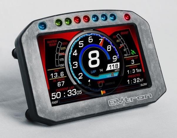
The Emtron ED5 5" digital dash display.
The ED5 features a full-colour, daylight readable screen surrounded by a tough, lightweight flow-moulded carbon fibre composite housing. Seven ultra-bright LEDs span the top of the display housing for RPM and shift light indication. Users can program them to ascend in specific increments based on RPM range and flash when it is time to shift. Brightness is user programmable on the fixed colour LEDs. Button functions are included in the supplied rear connector, allowing the user to mount remote buttons. Two additional programmable LEDs are located on the top of the housing on either side of the integrated LED shift lights.
2.0 Specification
- Full colour 5" display with 800 × 480 resolution
- Super bright sunlight readable with anti-glare filter (1000 cd/m²)
- IP66 water resistance allows for operation in marine and motorcycle applications
- Completely user definable CAN receive
- Seven LED RPM/shift light indicators on top of the housing (programmable and dimmable)
- Full graphics display with up to 6 different pages
- Odometer function
- Unit ships configured to receive the Emtron Display Tx Set 1 and Emtron Display Tx Set 2
- Completely user definable graphical layouts
- Stand-alone PC program to create and customize layouts
- Dual CAN bus
- Logging included in ED5L and ED7L versions only
Inputs
- 1 × ‘Headlight-in’ connection dims the dash and LEDs during night operation
- 2 × User extra switch inputs included
- 1 × Beacon Input
- 1 × Page Up Button
- 1 × Reset/Acknowledge Button
Communications
- 2 × CAN 2.0B — Baud Rate: 250kBaud, 500kBaud or 1Mbaud
Operating Temperature
- -30 to 85°C (-22 to 185°F)
Physical
- Enclosure Size 145mm × 102mm × 48mm
- Weight 331 grams
3.0 ED5 Wiring
3.1 ED5 Pinout
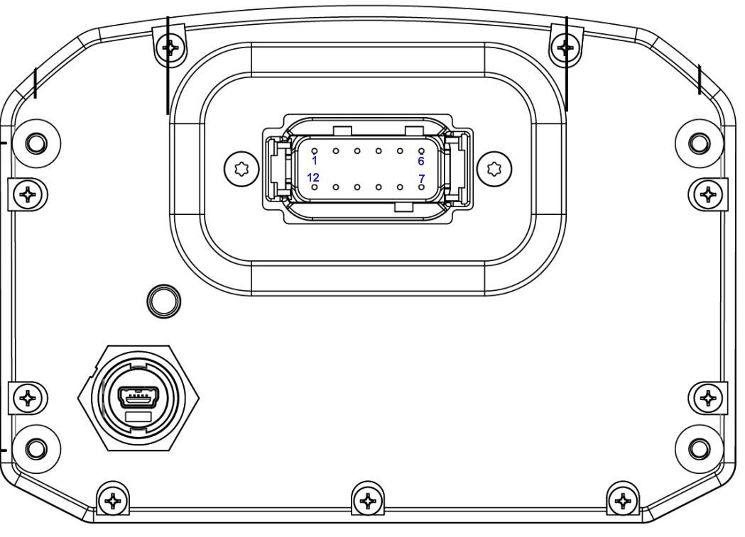
ED5 12-way DTM connector.
Table 3.1 — ED5 Pinout
| Pin | Function |
|---|---|
| 1 | 14 V Supply |
| 2 | Ground |
| 3 | CAN 1 Hi |
| 4 | CAN 1 Lo |
| 5 | CAN 2 Hi |
| 6 | CAN 2 Lo |
| 7 | Page Up |
| 8 | Reset/Ack |
| 9 | Night Mode |
| 10 | Beacon |
| 11 | User 1 Input (spare1) |
| 12 | User 2 Input (spare2) |
3.2 CAN Bus Wiring
The ED5 includes an on-board CAN termination resistor. It is switchable in the Emtron Display Editor software to allow the device to be wired at any position on the Bus, provided the termination resistor is turned off. If the ED5 is the only device connected to the ECU on the CAN bus, it is advised to switch the termination resistor on to provide termination at the display end of the CAN bus. CAN Bus termination must be done correctly by using a 120 ohm 0.25W resistor at each end of the bus system.
CAN bus wiring precautions
- CAN Bus High and Low are differential signals, so twisted pair MUST be used. Failing to do so will compromise the entire CAN Bus System.
- In some extreme environments, shielded twisted pair may be required to help with reliability and data integrity.
- The fewer connectors in any transmission system the better. Unnecessary connectors are almost guaranteed to present an impedance discontinuity and hence may cause reflections and data loss.
- CAN Bus termination must be done correctly by using a 120 ohm 0.25W resistor at each END of the bus system.
- Maximum stub length to a device from the main Bus is recommended at 0.3m, in accordance with the High-Speed ISO 11898 Standard.
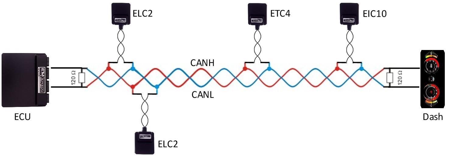
Figure 3.1 — CAN Bus wiring example: ECU and Dash at each end with 120 Ohm termination.
4.0 ED5 Software Installation
Download the latest version of Emtron Display Editor from https://emtron.world/downloads/. Install by opening the downloaded installer and following the instructions provided. Once the install is complete there will be a shortcut icon on the desktop.
4.1 Installing USB Drivers
USB drivers will be installed automatically.
5.0 ED5 Device Configuration
Once the ED5 and ECU are powered and connected to the CAN bus, the ECU must be configured to send CAN packets. The ED5 is shipped pre-configured with a sample configuration file that will allow communications, provided the ECU is set up to send the correct CAN IDs.
NoteNOTE The ED5 will not switch into run mode with the USB cable connected to the PC. Make sure this is unplugged for normal operation.
5.1 Emtune Settings
Ensure the ECU firmware Version is 2.17.0. If using earlier firmware versions, the display may still be operational; however, some functionality and channels will not be available.
Make sure the ECU is powered up and Online in Emtune. Go to Config View → Communications → CAN Bus 1 → CAN Bus 1 Setup → CAN 1 Baud Rate and set to 1Mbps.
Open the first available Channel. If there is nothing else already configured on the CAN bus, then CAN 1 Channel 1 would be the first available channel. If this channel is already used, simply select a channel that is free — the CAN 1 channel number selection has no effect on the operation. Set CAN 1 – Channel 1 and CAN 1 – Channel 2 as per the setup figures.
Store setting changes permanently in the ECU by pressing F4. Switch power OFF and ON to the ECU to ensure the updated CAN bus settings have been initialised. The ED5 should now be receiving and displaying live runtimes included in the Emtron Display Tx Set 1 and Emtron Display Tx Set 2.
6.0 Ordering Information
| Product | Part Number |
|---|---|
| Emtron ED5 | 54-052F |
Appendix 1 – ED5 Mechanical Drawing
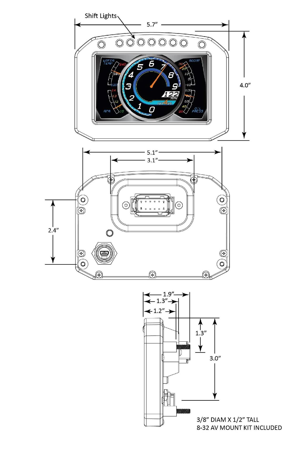
ED5 mechanical drawing.