Inertial Measurement Unit
Emtron ED Series Displays contain 6 axis Inertial Measurement Unit (IMU).
Output Channels
- G-Force Lateral
- G-Force Longitude
- G-Force Vertical
- Acceleration Lateral
- Acceleration Longitude
- Acceleration Vertical
- Angular Velocity X
- Angular Velocity Y
- Angular Velocity Z
- Roll
- Pitch
- Yaw
Calibration
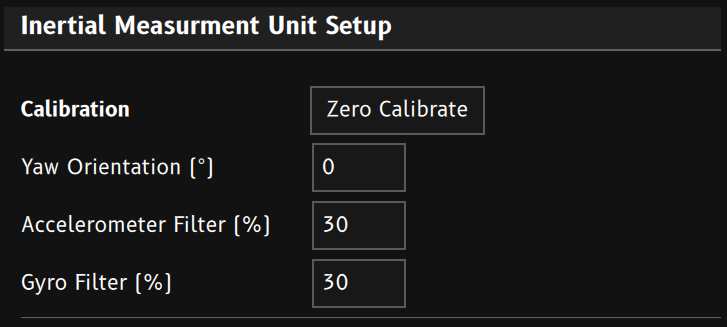
- Make sure car is parked on a flat level surface.
- Click
Zero Calibrateto put the IMU into calibration mode. The device will take 5 seconds worth of samples and find it’s vertical orientation. The calibration is stored in permanent memory in the device. - Once completed,
G-Force Verticalshould read close to 1.0G, whileG-Force LateralandG-Force Longitudeshould be 0.0G. - Drive the car forward and stop.
G-Force Longitudeshould go positive when accelerating and negative when braking.G-Force Lateralshould remain near zero. - If required, adjust the
Yaw Orientationvalue until the Longitudinal and Lateral G-Forces are aligned correctly.
In Field Calibration: Conditional Logic can be used to generate the
IMU Calibration Beginevent. This allows the IMU to be calibrated from a keypad button or similar user input.
Filtering
Accelerometer Filter and Gyro Filter values control how filtered the IMU measurements are.Values are a percentage (0 - 99.9%). Higher filtering gives a cleaner signal, but slows down the signals rate of change. Use the least filtering you can get away with.
Typical values would be 10-40 %