Air Mass Model Setup
Overview
The Air Mass Model defines how the ECU calculates the mass of air entering the engine.
Accurate air mass calculation is critical for two primary functions within the ECU:
The calculated air mass is used to determine the required fuel mass to achieve the commanded Lambda Target, before being converted into an injector pulse width using the injector configuration data.
The calculated air mass is used by the Engine Torque Model to estimate engine torque. Accurate air mass calculation is therefore essential to ensure Torque Control and Torque Reduction functions operate correctly.
Important Note: Torque and Air Mass.
The selected Air Mass Model forms the foundation of the ECU Fuel and Torque calculations and should be configured before starting engine tuning.
Just to restate this important point, the ECU calculates engine torque from the Air Mass defined by the Mass Model. This may be derived from Speed Density, TMF, a Mass Air Flow (MAF) Sensor, or another supported air-mass measurement method. The importance of correctly calibrating the selected Air Mass Model cannot be overstated. Accurate air mass modelling is fundamental to achieving accurate engine torque modelling and, consequently, correct operation of the ECU’s Torque Control and Torque Reduction functions.
Throttle Torque Reduction can only operate when the Air Mass Model Throttle Mass Flow (TMF) is enabled. TMF is required to accurately calculate the change in air mass across the throttle plate during throttle movements and can therefore provide accurate throttle torque reduction control.
The Throttle Mass Flow (TMF) air mass model cannot be used as a standalone air mass calculation and must always be blended with a secondary air mass model. At throttle pressure ratios above 0.9 (Post-Throttle Pressure / Pre-Throttle Pressure), the pressure differential across the throttle body becomes very small, significantly reducing the sensitivity and resolution of the TMF calculation. This requirement is referenced multiple times throughout the documentation due to its importance when configuring TMF based air mass models.
Different engine combinations may benefit from different air mass calculation strategies. Emtron provides several Air Mass Models to suit a wide range of applications. The ECU can calculate engine air mass using the following Air Mass Models:
Setup Options
| Value | Air Mass Model |
|---|---|
| 0 | Speed Density (MAP) |
| 1 | Speed Density (BAP) |
| 2 | Mass Air Flow (MAF) |
| 3 | Air Mass User 1 + Throttle Mass Flow (TMF) Blend |
| 4 | Speed Density (MAP) + Throttle Mass Flow (TMF) Blend |
| 5 | Emtron Air Mass Model (Custom) |
Air Mass Model Descriptions
Speed Density (MAP)
Calculates engine air mass using the Ideal Gas Law based on Manifold Absolute Pressure (MAP), Charge Temperature, Engine Displacement, and Volumetric Efficiency (VE).
See here for more information: MAP air mass
Speed Density (BAP)
Calculates engine air mass using Barometric Absolute Pressure (BAP) instead of manifold pressure. This mode is typically used on naturally aspirated engines operating with individual throttle bodies (ITBs), where manifold pressure is not a reliable indicator of engine load.
See here for more information: BAP air mass
Mass Air Flow (MAF)
Calculates engine air mass directly from the measured airflow provided by the configured Mass Air Flow sensor.
See here for more information: MAF air mass
Air Mass User 1 + Throttle Mass Flow (TMF) Blend
The final engine air mass is generated by blending the calculated Air Mass User 1 value and Throttle Mass Flow (TMF) calculation using the ratio defined by the Air Mass Blend Table.
When this mode is enabled the The Air Mass Blend Table becomes active:
Tuning -> Fuel -> Air Mass Model Blending Table
- 0% Blend = 100% Air Mass User 1
- 100% Blend = 100% Throttle Mass Flow (TMF)
See here for more information: TMF air mass
See here for more information: User 1 air mass
Speed Density (MAP) + Throttle Mass Flow (TMF) Blend
The final engine air mass is generated by blending Speed Density (MAP) value and Throttle Mass Flow (TMF) calculation using the ratio defined by the Air Mass Blend Table.
When this mode is enabled the The Air Mass Blend Table becomes active:
Tuning -> Fuel -> Air Mass Model Blending Table
- 0% Blend = 100% Speed Density
- 100% Blend = 100% Throttle Mass Flow
See here for more information: TMF air mass
See here for more information: MAP air mass
Important Notes: TMF Blending.
At throttle pressure ratios above approximately 0.9 (Post-Throttle Pressure / Pre-Throttle Pressure), the pressure differential across the throttle body becomes very small, reducing the resolution of the Throttle Mass Flow (TMF) calculation. This is why TMF must always be blended with an alternative air mass calculation method and cannot be used as the sole air mass model for engine operation.
The Air Mass Blend Table should therefore progressively transition from TMF to an alternative air mass calculation method as the throttle pressure ratio approaches 1.0
The Air Mass Blend Table forms part of the engine air mass model and must be finalised before tuning starts.
TMF tuning is accomplished by validating the Throttle Body Area Table
The TMF Correction Table can be used to make small adjustments to the TMF calculation if required. In most applications, little or no correction should be necessary.
Emtron Air Mass Model (Custom)
Uses the custom Emtron air mass model. See here for more information: Emtron air mass
Air Mass Blend Table
When Air Mass Model 3, 4 or 5 is selected, the Air Mass Blend table is enabled.
This table determines the contribution(ratio) of each air mass model used to calculate the final engine air mass.
Intermediate values proportionally blend between the selected air mass models.
See here for more information on Air Mass Blend Table : Air Mass Blend Table
Air Mass Bank Control
This option is only available using the Emtron Air Mass Model. See Emtron Air Mass Model
Air Mass Runtimes
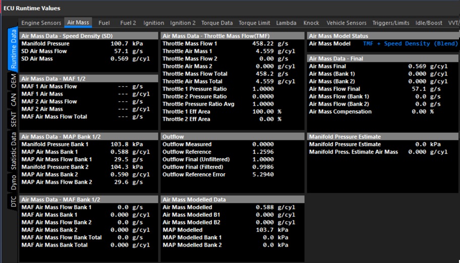
All ECU air mass related runtimes can be viewed from: ECU Runtime -> Air Mass
Note on Units: Air Mass Flow is expressed in units of g/s (grams per second), while Air Mass is expressed in units of g/cyl (grams per cylinder), representing the mass of air trapped in the cylinder during a single engine cycle.