Air Mass Modelled
Air Mass Modeling allows the ECU to blend different methods of air mass calculation to generate the Air Mass Modeled runtime
Air Mass Modelled Setup
This function blends the Air Mass (g/cyl) selected in Parameter 1 and 2 to give a “Air Mass Modelled” runtime in g/cyl.
This runtime can be used throughout the ECU. As an example it can be used used to run the Fuel Model, you can blend the air mass from
Throttle Mass Flow (TMF) to Speed Density (MAP) and use that result to run the engine i.e you can “favour” the TMF under lite to mid throttle and blend to MAP
under high load conditions (Fuel Model setting 3). See Fuel Model Setup for Fuel Model information.
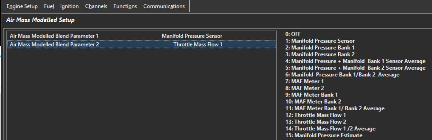
Air Mass Modelled Blend Parameters have the following options. Choose what two air flow calculations to use in the blend table:
0: OFF. Function is off
1: Manifold Pressure Sensor. Manifold Pressure
2: Manifold Pressure Bank 1. Bank 1 Manifold Pressure
3: Manifold Pressure Bank 2. Bank 2 Manifold Pressure
4: Manifold Pressure + Manifold Bank 1 Sensor Average. Average of MAP and MAP Bank 1
5: Manifold Pressure + Manifold Bank 2 Sensor Average. Average of MAP and MAP Bank 2
6: Manifold Pressure Bank 1/Bank 2 Average. Average of MAP Bank 1 and Bank 2
7: MAF Meter 1. MAF Sensor 1
8: MAF Meter 2.MAF Sensor 2
9: MAF Meter Bank 1. Bank 1 MAF Sensor
10: MAF Meter Bank 2.Bank 2 MAF MeSensorter
11: MAF Meter Bank 1/ Bank 2 Average, Average of MAF Bank 1 and Bank 2
12: Throttle Mass Flow 1.Throttle Mass Flow Bank 1
13: Throttle Mass Flow 2. Throttle Mass Flow Bank 2
14: Throttle Mass Flow 1 /2 Average. Average of TMF Bank 1 and Bank 2
15: Manifold Pressure Estimate. Estimated Manifold Pressure
Air Mass Modelled (Parameter Blend)
This mode generates new calculated runtime called “Air Mass Modelled (g/cyl)” which is a blend of two different air mass parameters. The “Blend Table”
determines the blend ratio between both parameters.
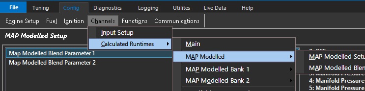
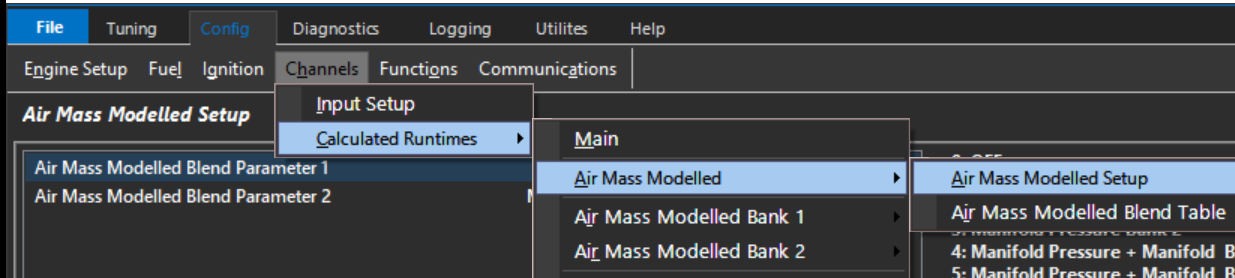
The configuration takes place in: Config -> Channels -> Calculated Runtimes -> Air Mass Modelled Setup. See Air Mass Modelled Setup
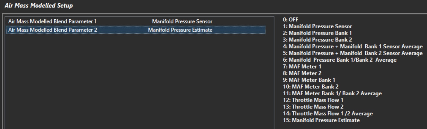
Air Mass Modelled Blend Parameter 1
Select the method of air mass calculation for Parameter 1
Air Mass Modelled Blend Parameter 2
Select the method of air mass calculation for Parameter 2
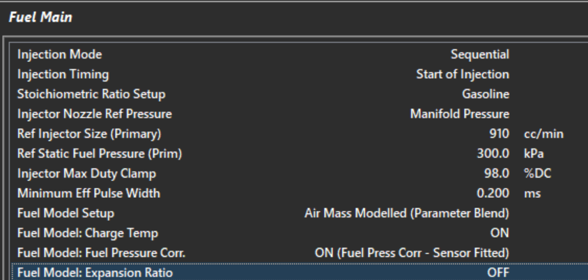
This Fuel mode is most commonly used when bending between Manifold Pressure Sensor and Manifold Pressure Estimate as shown above. (see further help on MAP Estimate).
If Air Mass Modelling is not being used, select the same runtime for both parameters or set Air Mass Modelled Blend Table to point towards the appropriate runtime.
Air Mass Modelled Blend Table
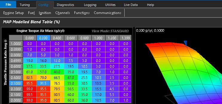
Speed Density (Parameter 1) over Throttle Mass Flow (Parameter 2) shown as an example
3D table with configurable axis that allows blending between to the two selected Air Mass Modelled Parameters.
0.0% : All Parameter 1
100.0% : All Parameter 2