The Air Mass Model defines how the ECU calculates the mass of air entering the engine.
Accurate air mass calculation is critical for two primary functions within the ECU:
The calculated air mass is used to determine the required fuel mass to achieve the commanded Lambda Target, before being converted into an injector pulse width using the injector configuration data.
The calculated air mass is used by the Engine Torque Model to estimate engine torque. Accurate air mass calculation is therefore essential to ensure Torque Control and Torque Reduction functions operate correctly.
Important Note: Torque and Air Mass.
The selected Air Mass Model forms the foundation of the ECU Fuel and Torque calculations and should be configured before starting engine tuning.
Just to restate this important point, the ECU calculates engine torque from the Air Mass defined by the Mass Model. This may be derived from Speed Density, TMF, a Mass Air Flow (MAF) Sensor, or another supported air-mass measurement method. The importance of correctly calibrating the selected Air Mass Model cannot be overstated. Accurate air mass modelling is fundamental to achieving accurate engine torque modelling and, consequently, correct operation of the ECU’s Torque Control and Torque Reduction functions.
Throttle Torque Reduction can only operate when the Air Mass Model Throttle Mass Flow (TMF) is enabled. TMF is required to accurately calculate the change in air mass across the throttle plate during throttle movements and can therefore provide accurate throttle torque reduction control.
The Throttle Mass Flow (TMF) air mass model cannot be used as a standalone air mass calculation and must always be blended with a secondary air mass model. At throttle pressure ratios above 0.9 (Post-Throttle Pressure / Pre-Throttle Pressure), the pressure differential across the throttle body becomes very small, significantly reducing the sensitivity and resolution of the TMF calculation. This requirement is referenced multiple times throughout the documentation due to its importance when configuring TMF based air mass models.
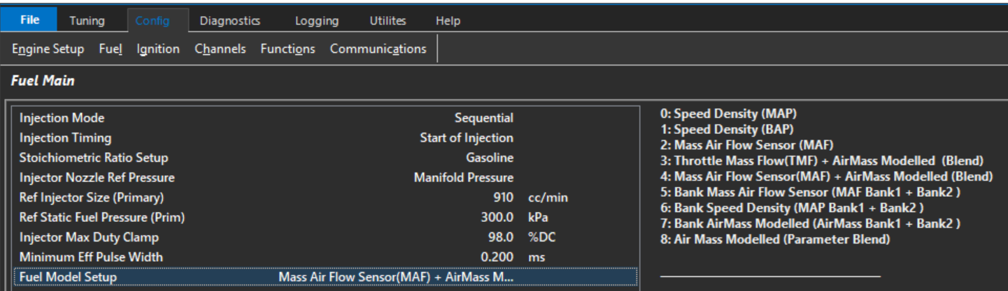
Different engine combinations may benefit from different air mass calculation strategies. Emtron provides several Air Mass Models to suit a wide range of applications. The ECU can calculate engine air mass using the following Air Mass Models:
Setup Options
Value
Air Mass Model
0
Speed Density (MAP)
1
Speed Density (BAP)
2
Mass Air Flow (MAF)
3
Air Mass User 1 + Throttle Mass Flow (TMF) Blend
4
Speed Density (MAP) + Throttle Mass Flow (TMF) Blend
5
Emtron Air Mass Model (Custom)
Air Mass Model Descriptions
Speed Density (MAP)
Calculates engine air mass using the Ideal Gas Law based on Manifold Absolute Pressure (MAP), Charge Temperature, Engine Displacement, and Volumetric Efficiency (VE).
Calculates engine air mass using Barometric Absolute Pressure (BAP) instead of manifold pressure. This mode is typically used on naturally aspirated engines operating with individual throttle bodies (ITBs), where manifold pressure is not a reliable indicator of engine load.
The final engine air mass is generated by blending the calculated Air Mass User 1 value and Throttle Mass Flow (TMF) calculation using the ratio defined by the Air Mass Blend Table.
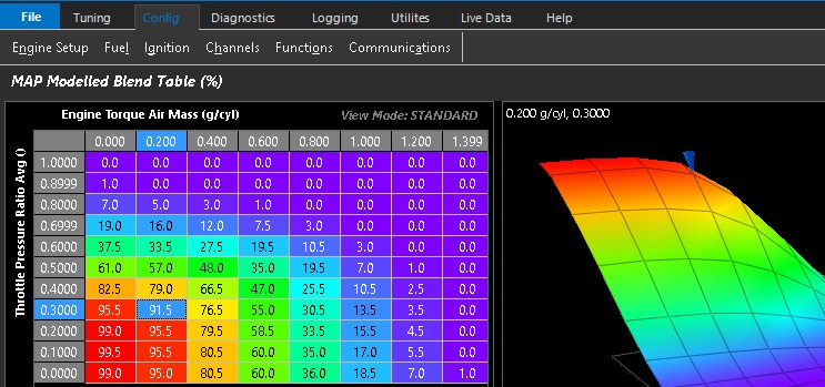
When this mode is enabled the The Air Mass Blend Table becomes active: Tuning -> Fuel -> Air Mass Model Blending Table
Speed Density (MAP) + Throttle Mass Flow (TMF) Blend
The final engine air mass is generated by blending Speed Density (MAP) value and Throttle Mass Flow (TMF) calculation using the ratio defined by the Air Mass Blend Table.
When this mode is enabled the The Air Mass Blend Table becomes active: Tuning -> Fuel -> Air Mass Model Blending Table
At throttle pressure ratios above approximately 0.9 (Post-Throttle Pressure / Pre-Throttle Pressure), the pressure differential across the throttle body becomes very small, reducing the resolution of the Throttle Mass Flow (TMF) calculation. This is why TMF must always be blended with an alternative air mass calculation method and cannot be used as the sole air mass model for engine operation.
The Air Mass Blend Table should therefore progressively transition from TMF to an alternative air mass calculation method as the throttle pressure ratio approaches 1.0
The Air Mass Blend Table forms part of the engine air mass model and must be finalised before tuning starts.
The TMF Correction Table can be used to make small adjustments to the TMF calculation if required. In most applications, little or no correction should be necessary.
Emtron Air Mass Model (Custom)
Uses the custom Emtron air mass model. See here for more information: Emtron air mass
Air Mass Blend Table
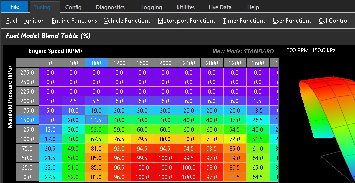
When Air Mass Model 3, 4 or 5 is selected, the Air Mass Blend table is enabled.
This table determines the contribution(ratio) of each air mass model used to calculate the final engine air mass.
Intermediate values proportionally blend between the selected air mass models.
This option is only available using the Emtron Air Mass Model. See Emtron Air Mass Model
Air Mass Runtimes
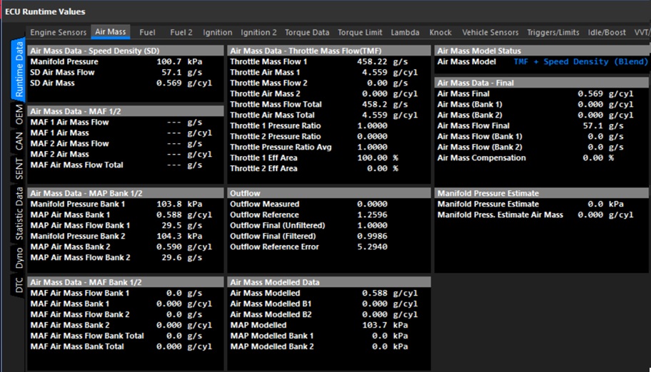
All ECU air mass related runtimes can be viewed from: ECU Runtime -> Air Mass
Note on Units: Air Mass Flow is expressed in units of g/s (grams per second), while Air Mass is expressed in units of g/cyl (grams per cylinder), representing the mass of air trapped in the cylinder during a single engine cycle.
Speed Density (BAP)
Speed Density (BAP Sensor)
Speed Density (BAP) mode is predominantly used in TPS only tuning methods.
This mode uses the same Fuel Model and equations as listed for mode 0 (Speed Density (MAP)), the only difference is the MAP sensor is replaced with the BAP sensor.
Speed Density (MAP)
Overview
The ECU’s primary Air Mass Model is Speed Density (MAP Sensor).. The basis of this calculation is derived using the Ideal Gas Law; PV = nRT
The ECU calculates the injection time for speed density using the following information:
Displacement volume per cylinder (cc).
Intake Manifold Air Pressure - MAP(kPa)
Lambda Target (La)
Stoichiometric Ratio of the Fuel (Stoich)
Injector Flow rate (cc/min)
Charge Temperature (DegC)
Fuel Density (g/ml)
Fuel Pressure (kPa)
Engine VE (%)
Gas Constant - R = 287J/Kg/K for Dry Air.
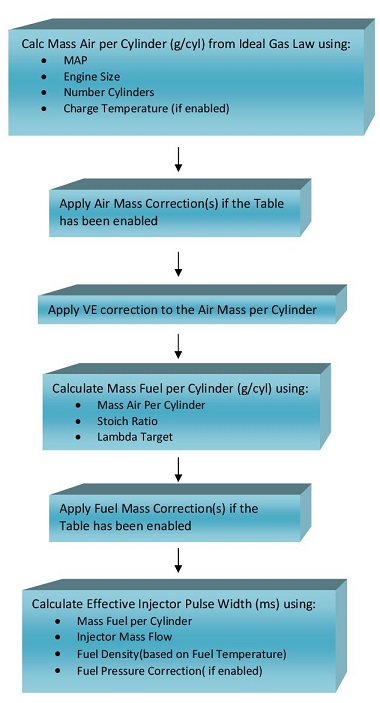
Using these inputs, the ECU calculates the mass of air trapped within each cylinder for every engine cycle. The calculated air mass is then used to determine the required fuel mass to achieve the commanded Lambda Target, before being converted into an injector pulse width.
Important Note
Since the air mass is calculated rather than measured directly, the accuracy of the Speed Density model depends heavily on correct calibration of the Volumetric Efficiency (VE) table(s).
In the predefined Speed Density (MAP) Air Mass Model, the pressure source is fixed to the Manifold Pressure input channel and cannot be changed.
If an alternative pressure source is required, this is only available when using the Emtron Air Mass Model (Mode 5):
Set Air Mass Model = Emtron Air Mass Model
Configure Calculation 1 or Calculation 2 as Speed Density
Configure the desired pressure source from: Config → Air Mass → Speed Density Setup → Speed Density MAP Source
Speed Density Setup
The Speed Density setup parameters are configured from: Config → Air MAss → Speed Density (SD) Setup
The following settings are used to configure the Speed Density Air Mass Model.
VE Table Control
Selects the method used to generate the final Volumetric Efficiency (VE) value used by the Speed Density calculation (Non-Banked Mode).
This setting is only available when the selected Air Mass Model uses Speed Density.
Value
Mode
0
Not Available
1
Table 1
2
Table 2
3
Not Available
4
Cal Slot
5
Not Available
6
Z-Axis
7
VE Blend (VE Table 1 / VE Table 2)
Table 1: Uses VE Table 1 exclusively for all engine operating conditions.
Table 2: Uses VE Table 2 exclusively for all engine operating conditions.
Cal Slot: Allows the active VE table to be switched dynamically in real time using the Calibration (Cal) Slot Table function. See : Tuning → Cal Control
Z-Axis: Enables a user configurable third operating axis to blend or switch between VE Table 1 and VE Table 2. The Z-axis can use any available ECU runtime making it suitable for applications such as:
Variable camshaft systems (VTEC/VVL)
Alternate fuel calibrations
VE Blend: Uses the VE Blend Table to generate the final VE value by blending between VE Table 1 and VE Table 2.
0.0% = All VE Table 1
50.0% = Equal blend of VE Table 1 and VE Table 2
100.0% = All VE Table 2
Speed Density Charge Temperature Enable
When enabled, the ECU includes Charge Temperature in the Speed Density air mass calculation. The ECU automatically corrects the calculated air mass based on Charge Temperature Estimate using the Ideal Gas Law. For this reason, the Charge Temperature Compensation Tables should initially be configured to zero (not used).
When disabled, the Speed Density model assumes a fixed charge temperature of 20°C and the Charge Temperature Compensation Tables are therefore required to provide the necessary fuel compensation.
Recommended Setting: ON
VE Expansion Ratio
The VE Expansion Ratio feature uses the relationship between:
Exhaust Manifold Pressure (EMAP)
Manifold Absolute Pressure (MAP)
Engine Static Compression Ratio
to correct the effective volumetric efficiency of the engine as exhaust backpressure changes.
NOTE: VE Expansion Ratio correction operates only when the Air Mass Model is configured for Speed Density mode as this is a VE correction.
This is particularly beneficial on turbocharged engines operating at high boost pressures where increasing exhaust backpressure can significantly influence cylinder filling efficiency.
Selects the pressure source used by the Speed Density calculation. This setting is ONLY available when the selected Air Mass Model is Emtron Air Mass Model.
For all predefined Air Mass Models this setting defaults to the Manifold Pressure input and cannot be modified.
The following pressure sources are available:
Value
Pressure Source
0
Off
1
Barometric Pressure
2
Manifold Pressure
3
Manifold Pressure - Bank 1
4
Manifold Pressure - Bank 2
5
Manifold Pressure - Bank 1 / 2 Average
6
Boost Pressure
7
Boost Pressure - Bank 1
8
Boost Pressure - Bank 2
9
Boost Pressure - Bank 1 / 2 Average
10
MAP Estimate
11
User Pressure 1
12
User Pressure 2
13
User Pressure 3
14
User Pressure 4
Speed Density MAP Bank 1 and Bank 2 Source.
Selects the pressure source used for each individual bank Speed Density calculation.
This setting is only available when:
The selected Air Mass Model is Emtron Air Mass Model
Air Mass Bank Control is enabled
The same pressure source options described in Speed Density MAP Source are available for both Bank 1 and Bank 2 calculations.
Example:
MAP = 252kPa
Charge Temperature = 30.7 DegC
Volume Per Cylinder = 666.6
Stoich Ratio = 9.9
Lambda Target = 0.785
Engine VE = 96.6 %
Fuel Mass (g) = 0.2395
In this basic example, if the cylinder achieves 96.6% volumetric efficiency, then 0.2395 grams of fuel is required to achieve a Lambda Target of 0.785.
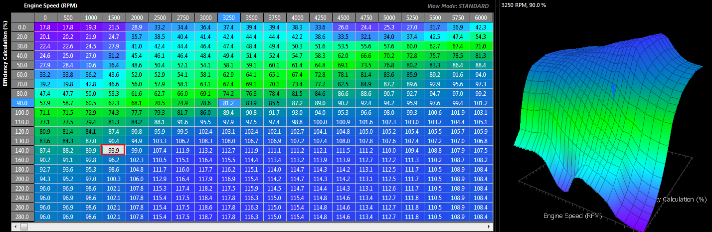
The VE Table(s) define the volumetric efficiency of the engine at varying engine speeds and loads and represent the True VE of the engine. A typical table is shown in Figure 1 for a turbo charged engine.
Fuel VE Table
Figure 1
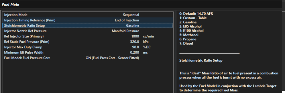
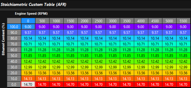
Also, the Stoichiometric Ratio will vary with Fuel Type. A Single Zone if the fuel type is fixed (Figure 2) can be used or a Table allowing the ECU to constantly correct for varying alcohol content. See Figure 3.
Stoich Ratio Setup (single) Figure 2
Stoich Ratio Setup (table) Figure 3
Notes on Effective Pusle width
Once the required Fuel Mass has been determined from the calculated Air Mass, the ECU calculates the effective injector pulse width using:
Injector Size
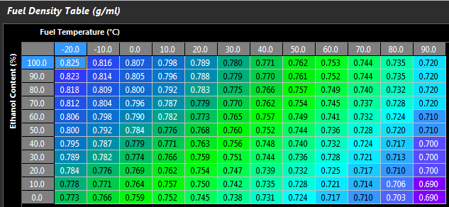
Fuel Density. Fuel density is used to convert between fuel mass and fuel volume and can be a function of both Fuel Temperature and Alcohol Content. A typical Fuel Density table is shown below in Figure 4
Fuel Pressure Correction. Fuel Pressure Correction is based on the injector flow relationship described by Bernoulli’s Equation and allows the effective injector flow rate to be adjusted as the differential pressure across the injector changes.
Note: Fuel Pressure Correction is only applied when enabled using the Config -> Fuel -> Fuel Main → Fuel Pressure Corr. setting.
Fuel Density Table Figure 4
Mass Air Flow Sensor (MAF)
Overview
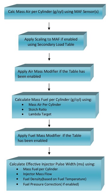
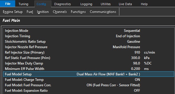
The Air Flow Sensor(s) provides a measured Air Mass Flow in g/s. The ECU then converts this into air mass per cylinder (g/cyl) giving actual Air Mass into the Engine.
The following MAF input channels can be used:
Mass Air Flow Sensor(s) 1 and 2
Mass Air Flow Bank Sensor(s) 1 and 2 can be used
The ECU will search which channel(s) are enabled and use those inputs. “Mass Air Flow Sensor” takes priority over “Mass Air Flow Bank Sensor”. For example if both
Mass Air Flow Sensor1 and Mass Air Flow Sensor2 input channels are configured the ECU will automatically use both inputs.
MAF systems are more flexible in their ability to compensate for engine changes(like altitude and IAT) since they actually measure airflow instead of calculating it like the Speed Density Fuel Model. It also greatly reduces the tune time as you no longer need to adjust the fueling based on the VE of the Engine… its automatically accounted for by the MAF sensor.
However they also have limitations around restriction and sensor range on high power engines.
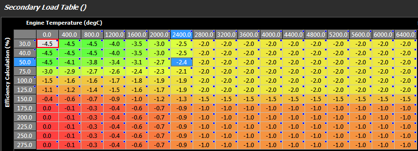
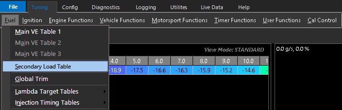
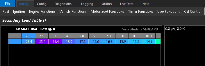
Once the Mass Air has been measured, if the MAF requires further scaling this can be done using a 3D Table. In the real world “small” corrections will need to be applied. This can be done using the Secondary Load Table which will allow a +/- percentage correction to be applied.
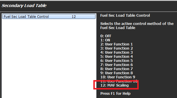
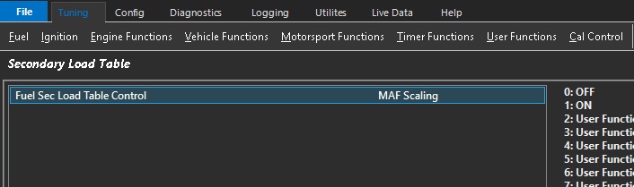
A Typical example is shown in below. Table Control should be used to put the Secondary Load Table into this “special” mode shown below
Secondary Load Table used for MAF Sensor
Table Control for Secondary Load Table
Once the Air Mass has been determined, the Stoichiometric Ratio and Lambda Target are used to generate a Fuel Mass (g). The Stoichiometric Ratio will vary with Fuel Type. A Single Zone if the fuel type is fixed can be used or a Table allowing the ECU to constantly correct for varying alcohol content.
Once the Fuel Mass is determined, the Effective Injector Pulse Width can be calculated using:
Injector Size
Fuel Density. Fuel Density can be a function of both Fuel Temperate and Alcohol Content.
Fuel Pressure Correction. The Fuel Pressure Correction is a Fluid Dynamics equation. It allows the injector flow rate to be adjusted as the differential pressure across the injector changes. NOTE: This correction MUST be enabled using the “Fuel Model : Fuel Pressure” setting
Flow Chart Overview for Mass Air Flow Sensor Fuel Model:
Throttle Mass Flow Setup
Overview
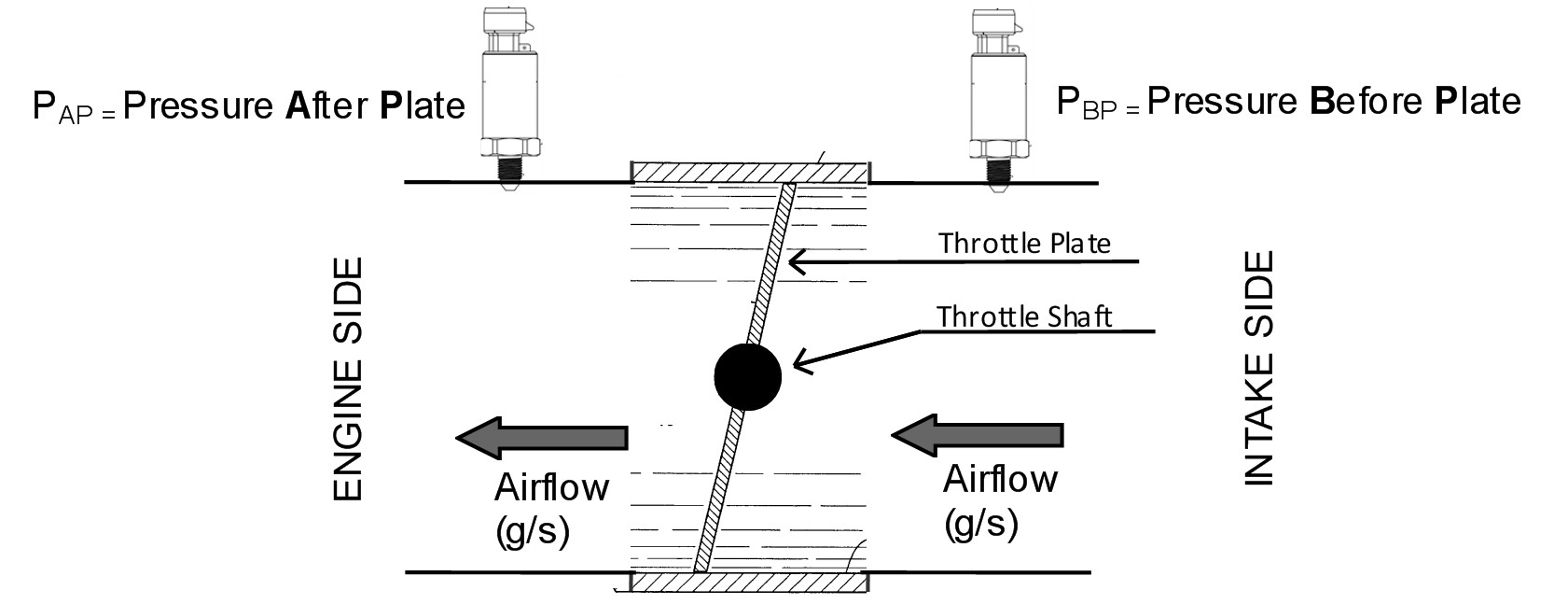
Throttle Mass Flow (TMF) as the name indicates, is the rate at which air mass is flowing through a throttle body in units of grams/second (g/s). Using the throttle body size, throttle area, temperature, pre and post throttle pressures,the ECU can very accurately calculate air flow through the throttle body and therefore into the engine; this is known as the TMF Calculation. Other sensors that also generate air mass flow (g/s) data are Manifold Pressure and MAF sensors. The TMF Calculation is just another method of determining air mass flow and has benefits over MAP and MAF as discussed further down.
The image below illustrates the basic elements required to calculate TMF.
Getting into more detail, the flow through a throttle body is governed by three physical elements, Conversation of mass, Newtons second law of motion for fluids and Conservation of energy. By combining these elements the ECU can model the flow of fluid through the throttle body accounting for throttle plate thickness and throttle shaft size. By then including real-time data such as the pressure ratio across the throttle plate and the instantaneous throttle area, the ECU can precisely calculate the mass flow rate through a throttle body.
Although these calculation are complex, the TMF setup process for the user is kept as simple as possible with the following inputs and setup required:
Sensor Inputs required
Pressure Before the throttle Plate
Pressure After the throttle Plate
Temperature
Setting required
Throttle Body Size
Throttle Area to Servo Position Correlation Table (Throttle Body Area Table)
The TMF calculation can be summarised by the following equation:
Throttle Mass Flow (g/s) = ( Pafter / Pbefore) x Throttle Area x Modelled throttle body fluid dynamics equation
Settings
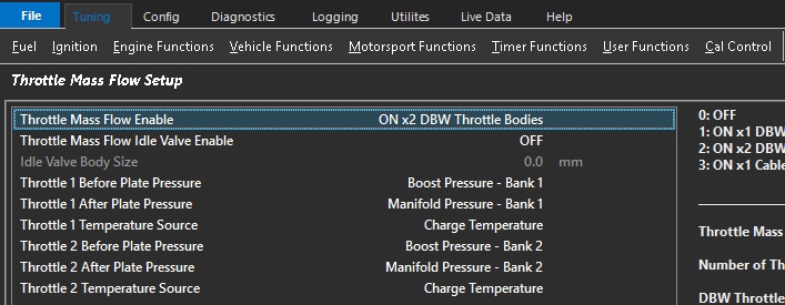
Config-> Air Mass -> Throttle Mass Flow (TMF) Setup
Throttle Mass Flow Enable
Allows the TMF function to be enabled. At this point the ECU is only calculating air mass flow into the engine. Once setup other functions like the Launch and Idle Speed Control can be configured to use the TMF calculated air mass data.
Select which type of throttle system you have:
1x DBW Throttle
2x DBW Throttle
1x Cable Throttle
Throttle Body Size
The Throttle Body inside diameter in millimeters.
Throttle Body Size Scaler
Allows the Throttle Body diameter to be scaled to correct for any system calibration errors. So 60.0 mm diamter with 2.5% scaler gives a throttle diamter of 61.5mm
Default Value = 0.0%
Throttle Mass Flow Filter Mode
This setting controls the Filtering of the Outflow function, a critical part of the TMF Calculation.
Select the Emtron Default to use the Emtron pre-calibrated filter table. Alternativity, for advanced users these default values can be edited using the Custom Table option.
See Tuning -> Air Mass -> Throttle Mass Flow (TMF) User Filter Table
Throttle Mass Idle Valve Enable
Enables the Idle Valve Area to be accounted for in the TMF calculation; the Throttle Body Area AND Idle Valve Area are used to give a Total Area.
Normally only required on a Cable Throttle when an external Idle Air Bleed is used.
Throttle Before Plate Pressure
Pressure source before throttle plate
Commonly Boost Pressure
Also referred to as Charge Pressure
Normally aspirated vehicles can use Barometric Pressure as Pre Throttle pressure source
Throttle After Plate Pressure
Pressure source after throttle plate
Commonly Manifold Pressure
Throttle Temperature Source
The Air temperature input used in the TMF Calculation
Throttle Body Area
Gives the direct relationship between Throttle Area and Servo Position.
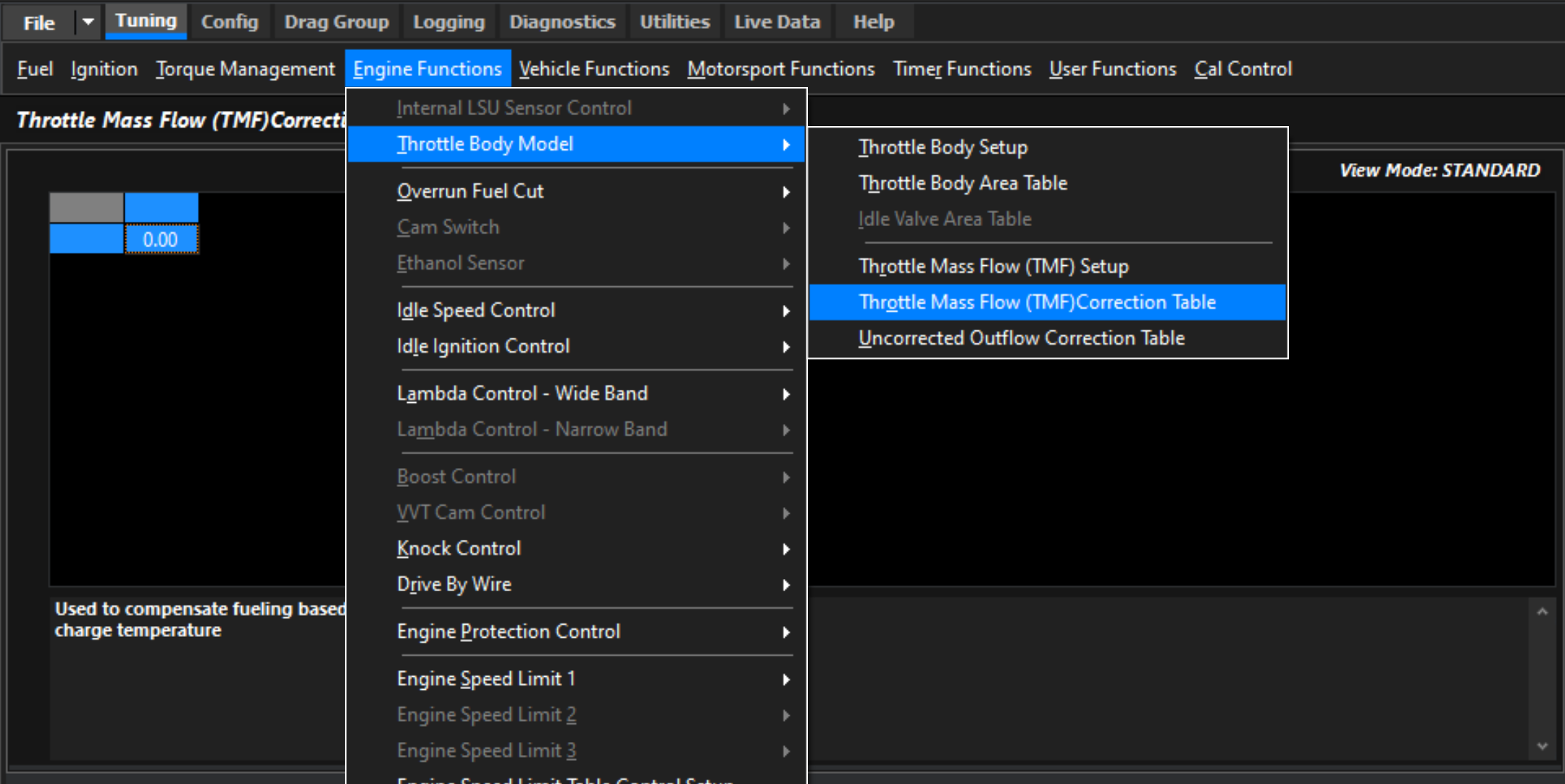
See Tuning -> Air Mass -> Throttle Body Model -> Throttle Body Area Table
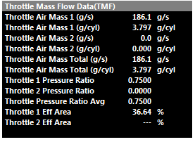
Throttle Mass Flow Runtimes
The following TMF calculated runtimes are generated. See the Runtime menu (F3) Engine Data Calculated tab.
Throttle Air Flow is expressed in units of g/s (grams per second), while Throttle Air Mass is expressed in units of g/cyl (grams per cylinder), representing the mass of air trapped in the cylinder during a single engine cycle.
Throttle Pressure Ratio is the ratio of Pre Throttle Pressure sensing vs Post Throttle pressure sensing (Boost Pressure vs MAP Pressure most commonly)
Throttle Eff Area is the calculated Throttle Area using the Servo Position and the Throttle Body Area lookup table.
All these runtimes can be utilized within other functions.
Functions that can utilize the TMF Calculation
The following functions can use the air mass data generated from the TMF calculation:
Fuel Model
Option 3: Blend - MAP Modelled + Throttle Mass Flow. TMF Fuel Model calculations can offer advantages when the throttle pressure ratio is low (partial throttle) and respond much faster in transient conditions.
For more information see the Fuel Model section.
Idle Speed Control
Option 6: DBW 1 TMF
Option 7: DBW 1+2 TMF
This allows the Idle Speed control to target Mass Flow Rate of g/s. The Throttle Mass Flow (TMF) idle speed control function delivers extremely accurate and rapid idle calculation based on actual engine’s airflow requirements. See TMF Idle Speed Control section for more information
Launch Control
Option 2: Torque Limiting.
The TMF is used to control throttle plate position to achieve a target torque and target launch engine speed.
Tuning TMF
Once TMF is appropriate set up, it can make mapping the engine when it is in use very fast. Using TMF wherever possible is strongly advised by Emtron, especially depending on what kind of dynamometer being used, test conditions, and more – often part throttle and proper transient setup is often forgiven due to time constraints.
Version 1.0
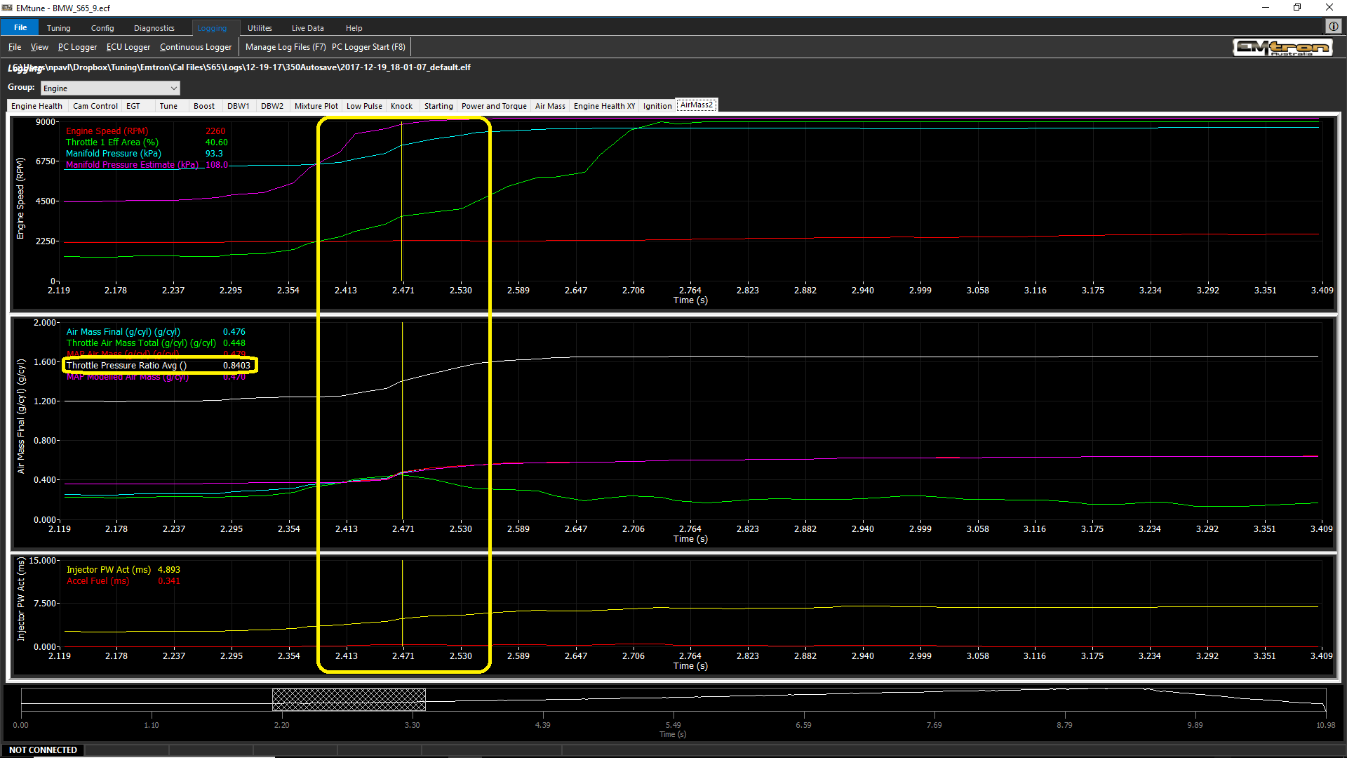
Due to strictly calculating airflow via pressure ratio, the calculation will become invalid at a near equal pressure ratio through the throttle.
Gradually accelerate the engine under load and increase to increase the throttle area demand/effective area.
** Final air mass calculation which can be affected by engine speed (and more) can affect the optimal blend point. This is why most default configurations for the Fuel Model Blend Table include Air Mass Final runtimes.
In this particular case the TMF signal at around 0.830 throttle pressure ratio is being unusable.
At this same moment, the Air Mass Modelled/blended calculation is stable and can be blended in.
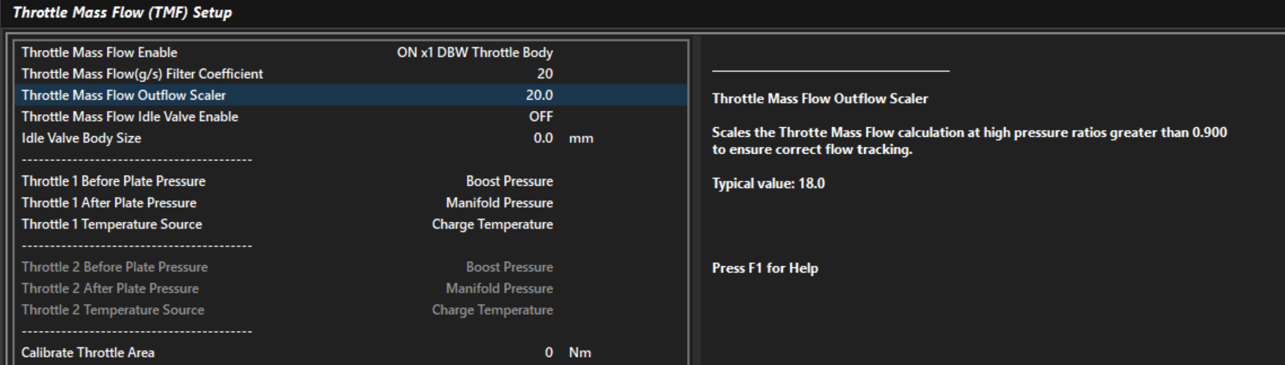
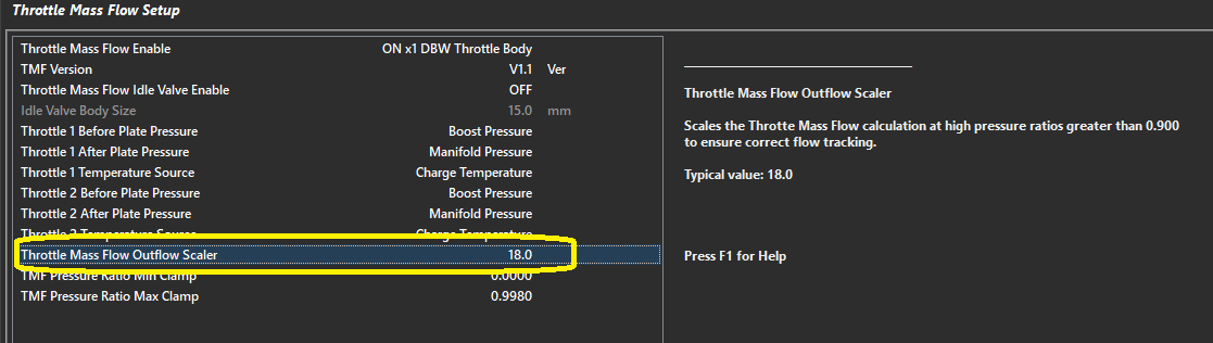
And/or TMF Out-flowing can generate correct TMF values.
TMF Outflowing calculates TMF airflow when pressure ratio cannot.
Improper “Outflow Scaler” setting. Adjust Throttle Mass Flow Outflow Scaler to correct
Throttle Mass Flow Air Flow values can only be compared to validated/tuned air flow values (tuned) such as MAP Air Mass or MAF Air Mass.
TMF Correction Table
This correction table essentially exists to help remove an error remaining in the system across a wide variety of load & rpm conditions.
Demonstrating error in TMF Calculation that needs to be corrected in TMF Correction Table
Tuning the Throttle Body Area Table
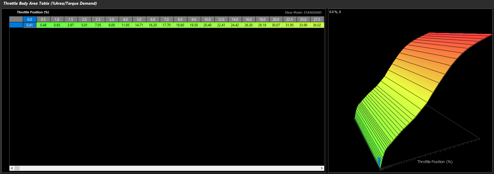
The Throttle Body Area table tells the ECU how much actual throttle area is effective at different throttle positions. This is key to the ECUs further Torque Managing functions, as accurate air mass measurement and actual engine torque go hand in hand.
For torque management, Throttle Area Demand can be manipulated which will be directly proportional to air mass when this is configured correctly
Tuning -> Engine Functions -> Throttle Body Model -> Throttle Body Area Table
This 2D table is all that is needed to appropriately map the given throttle area vs throttle position. As mentioned previously, this allows for extremely fast and accurate mapping of the engine when TMF is active.
It is important to understand that the Pedal Demand and other targeting of throttle area will target the "unit location" in this table, which will then correspond to the DBW Servo Position.
This means, there could be little relationship between Throttle Area Demand and actual DBW Servo Position on fully tuned setups.
Blend tables must be configured completely before tuning
There are multiple ways to calibrate the appropriate throttle area.
Method 1 – Torque verification
With calculated torque channels configured and functional, tuning the Engine Torque (TMF) channels to match the standard Engine Torque channels will allow full mapping of the Throttle Area table. See Torque Management Tuning
Method 2 – Matching other forms of Air Mass measurement
If the application is using a calibrated MAF sensor. Then the throttle area % can be adjusted and matched to TMF air mass VS MAF air mass at different throttle/DBW servo positions.
The same can be done matching TMF air mass VS MAP air mass
MAF/MAP air mass must be validly running the engine - running the commanded lambda target, etc
Method 3 – Matching Lambda
If no MAF sensor is available, setting fuel trims to 0 (or near 0), you can adjust the throttle area to match the target mixture very quickly.
Some extreme applications where live Lambda is unstable may be more difficult to map with Method 3
💡️ Tuning Tip
Per the Matching Lambda validation method, the Throttle Area Table is used to quickly tune the engine operating in TMF by simply manipulating the table at the various throttle areas to match the Lambda Target Table values for that given load. When the correct air fuel ratio is achieved, the Throttle Area Table is essentially validated for the purpose of running the engine. To do this the wideband lambda control should be turned off and the blend bias toward TMF be set to 100%.
Air Mass User 1
Overview
Air Mass User 1 allows the user to create a custom air mass calculation by combining two independent air mass sources. The resulting Air Mass User 1 runtime can then be used throughout the ECU wherever an air mass value is required. A Blend Table is used to determine the contribution of each source to the final air mass value.
This provides a flexible method of constructing advanced air mass calculation strategies that are not possible using the predefined Air Mass Models alone.
The configuration takes place in:
Config -> Air Mass -> Air Mass User 1 Setup. See Air Mass Model Setup
The Blend Table is configured from: Tuning → Air Mass → Air Mass User 1 Blend Table
Air Mass User 1 Setup
The Air Mass User 1 Setup configures the two air mass calculations used to generate the final Air Mass User 1 runtime.
Two independent inputs are available:
Air Mass User 1 Blend Parameter 1
Air Mass User 1 Blend Parameter 2
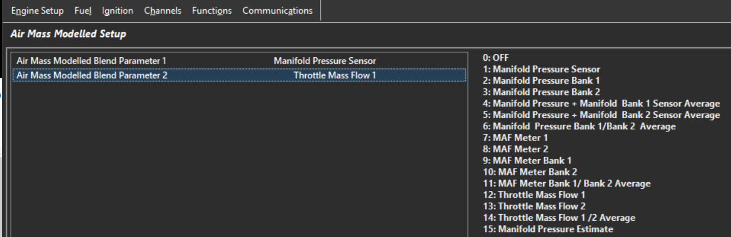
Air Mass User 1 Blend Parameters have the following options. Select the two air mass calculations that will be blended together to generate the final Air Mass User 1 runtime:
Value
Blend Parameter
0
Off
1
Manifold Pressure Sensor
2
Manifold Pressure Bank 1
3
Manifold Pressure Bank 2
4
Manifold Pressure + Bank 1 Sensor Average
5
Manifold Pressure + Bank 2 Sensor Average
6
Manifold Pressure Bank 1 / Bank 2 Average
7
MAF Meter 1
8
MAF Meter 2
9
MAF Meter Bank 1
10
MAF Meter Bank 2
11
MAF Meter Bank 1 / Bank 2 Average
12
Throttle Mass Flow 1
13
Throttle Mass Flow 2
14
Throttle Mass Flow 1 / 2 Average
15
Manifold Pressure Estimate
Air Mass User 1 Blend Parameter 1
Select the method of air mass calculation for Parameter 1
Air Mass User 1 Blend Parameter 2
Select the method of air mass calculation for Parameter 2
A common application is blending between Manifold Pressure Sensor and Manifold Pressure Estimate (see further help on MAP Estimate).
If blending is not required, configure both parameters to use the same air mass source or configure the blend table to fully favour the desired calculation method.
Air Mass User 1 Blend Table
The example above shows Speed Density configured as Parameter 1 and Throttle Mass Flow (TMF) configured as Parameter 2.
The Air Mass User 1 Blend Table is a three-dimensional table with configurable axes that determines the blend ratio between the two selected Air Mass User 1 parameters.
0.0% = All Parameter 1
100.0% = All Parameter 2
Air Mass Model Blend Table
Overview
The Air Mass Blend Table defines the contribution of two air mass calculations used to generate the final engine air mass value.
The table output is expressed as a percentage and determines the weighting applied to each air mass calculation based on the selected Air Mass Model configuration.
A value of:
0.0% uses 100% of the primary air mass calculation.
100.0% uses 100% of the secondary air mass calculation.
50.0% uses an equal contribution from both calculations.
This allows the ECU to transition smoothly between two air mass calculation methods as engine operating conditions change, combining the advantages of each model over different areas of the engines operating range.
The Air Mass Blend Table is configured from:
Tuning → Fuel → Air Mass Model Blend Table
Air Mass Model 3: Air Mass Modelled + Throttle Mass Flow (TMF) Blend**
0.0% → 100% Air Mass Modelled
100.0% → 100% Throttle Mass Flow (TMF)
Air Mass Model 4: Speed Density (MAP) + Throttle Mass Flow (TMF) Blend**
0.0% → 100% Speed Density (MAP)
100.0% → 100% Throttle Mass Flow (TMF)
Air Mass Model 5: Emtron Air Mass Model
0.0% → 100% Air Mass Model Calculation 1
100.0% → 100% Air Mass Model Calculation 2
The calculation methods used by Calculation 1 and Calculation 2 are configured from the Emtron Air Mass Model setup page.
ℹ️ Important Note: Air Mass Validation*
When an Air Mass Blend mode is enabled, both air mass calculations continue to operate simultaneously regardless of the blend ratio currently being applied.
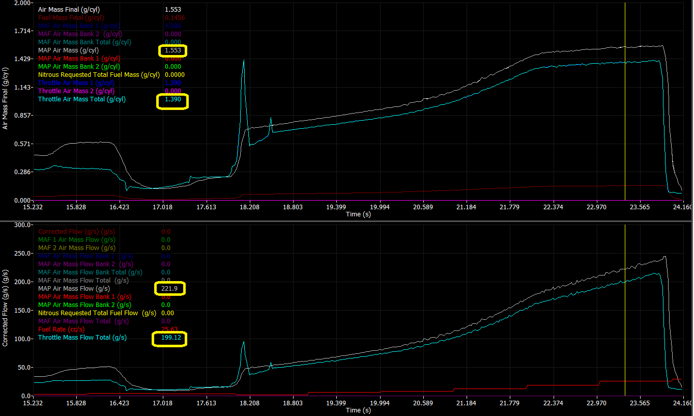
This allows the individual air mass calculations to be logged and compared directly against one another.
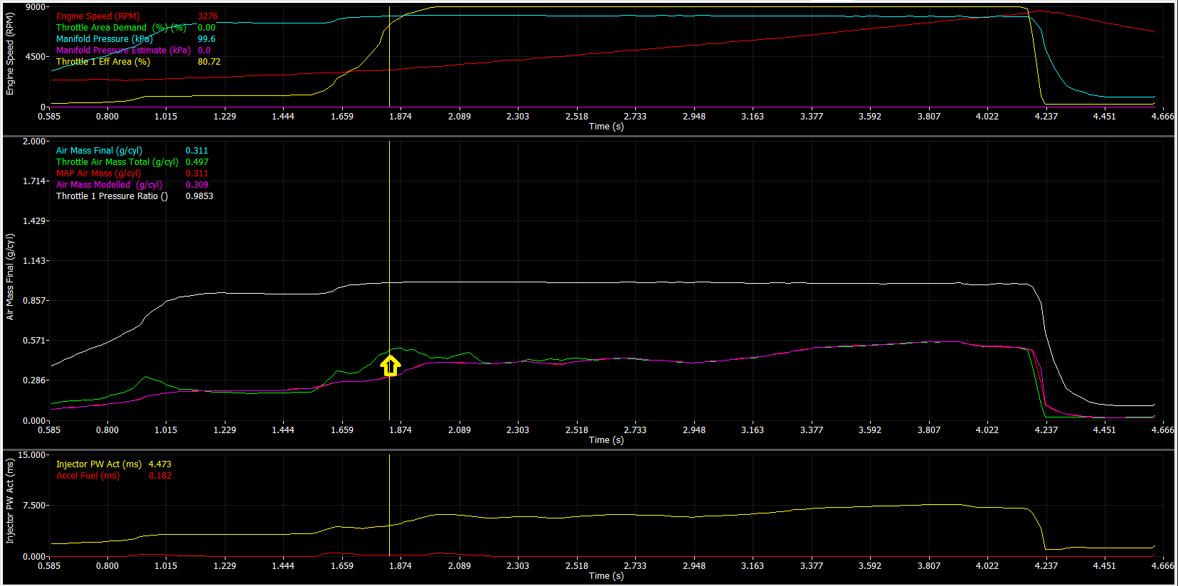
If both air mass models have been calibrated correctly, the calculated air mass values should closely overlay one another when operating under the same engine conditions.
For example, when using Speed Density + TMF Blend, the calculated Speed Density Air Mass and TMF Air Mass should produce similar air mass values for a given engine speed and load condition.
Significant differences between the two calculations typically indicate calibration errors within one of the air mass models, such as:
Volumetric Efficiency (VE) calibration errors
TMF model calibration errors
Throttle Body Area table errors
Charge Temperature model errors
Sensor scaling or sensor placement issues
Comparing multiple air mass models in this manner provides a powerful method for validating the engine air mass calibration and improving overall model accuracy.
Below is an example datalog illustrating the correlation between the calculated Speed Density and TMF air mass values under the same operating conditions.
Emtron Air Mass Model
Overview
The Emtron Air Mass Model allows the ECU air mass calculation to be customised using one or two independent air mass calculation methods.
Most applications can be accurately modelled using the predefined Air Mass Models (0 to 4) and no further customisation is required. The Emtron Air Mass Model is intended for advanced applications requiring custom air mass calculations or blending between multiple air mass calculation methods.
Two independent air mass calculations are available:
Air Mass Model Calculation 1
Air Mass Model Calculation 2
Each calculation can be configured to use one of the following air mass calculation methods:
Value
Calculation Method
0
Off
1
Speed Density
2
Mass Air Flow Sensor (MAF)
3
Throttle Mass Flow (TMF)
4
Air Mass Modelled
Single Calculation Mode
If only a single air mass model is required, configure Calculation 1 as required and set Calculation 2 to Off.
In this configuration, the ECU uses the output of Calculation 1 as the final engine air mass value.
Dual Calculation Blend Mode
For applications requiring the advantages of multiple air mass calculation methods, both Calculation 1 and Calculation 2 may be enabled simultaneously.
When both calculations are enabled, the ECU uses the Air Mass Model Blend Table to determine the contribution of each calculation to the final air mass value.
0.0% Blend = 100% Calculation 1
100.0% Blend = 100% Calculation 2
50.0% Blend = Equal contribution from Calculation 1 and Calculation 2
This allows the ECU to transition smoothly between two air mass calculation methods as engine operating conditions change, combining the advantages of each model over different areas of the operating range.
Application Example: Speed Density + Throttle Mass Flow (TMF)
A common application of the Emtron Air Mass Model is blending Speed Density and Throttle Mass Flow (TMF) calculations to take advantage of the strengths of each method.
At low Pressure Ratios (PR) across the throttle body, such as idle, cruise and part-throttle operation, Throttle Mass Flow (TMF) provides superior airflow estimation due to the strong relationship between throttle pressure drop and mass flow.
As the throttle opens and the pressure ratio across the throttle approaches 1.0, the pressure drop across the throttle body becomes very small and the accuracy and sensitivity of TMF reduces. Under these conditions, Speed Density generally provides a more accurate estimation of cylinder air mass.
The Air Mass Model Blend Table can therefore be configured to:
Use predominantly TMF at low pressure ratios.
Progressively transition towards Speed Density as the pressure ratio approaches 1.0.
Operate using predominantly Speed Density during high load and wide open throttle operation.
This approach combines the excellent transient response characteristics of TMF with the steady-state accuracy of Speed Density.
At throttle pressure ratios above approximately 0.9 (Post-Throttle Pressure / Pre-Throttle Pressure), the pressure differential across the throttle body becomes very small, reducing the resolution of the Throttle Mass Flow (TMF) calculation. This is why TMF must always be blended with an alternative air mass calculation method and cannot be used as the sole air mass model for engine operation.
The Air Mass Blend Table should therefore progressively transition from TMF to an alternative air mass calculation method as the throttle pressure ratio approaches 1.0.
The Air Mass Blend Table forms part of the engine air mass model and must be finalised before tuning starts.
The TMF Correction Table can be used to make small adjustments to the TMF calculation if required. In most applications, little or no correction should be necessary.
Air Mass Bank Control
Air Mass Bank Control allows the ECU to independently calculate the engine air mass for each cylinder bank. This option is only available using the Emtron Air Mass Model.
When enabled, each bank operates as an independent air mass model and requires the appropriate sensors and inputs to support bank-specific airflow calculations.
Typical examples include:
Independent inlet manifolds.
Dual throttle body systems.
Dual plenum engines.
Engines equipped with bank specific pressure, temperature or airflow sensors.
Additional Information: Bank Control
1) Engines with inlet manifolds connected by a balance tube or crossover passage may not exhibit true banked airflow behaviour. Any pressure differential between the manifolds will result in airflow transfer through the balance passage, reducing the effectiveness and accuracy of independent bank air mass calculations.
2) Air Mass Bank Control is available for all Air Mass Model types.
2) Ensure the Bank Cylinder Setup table is configured correctly before enabling Bank Mode.
3) Air Mass Bank Control is not compatible with Staged Injection operation.
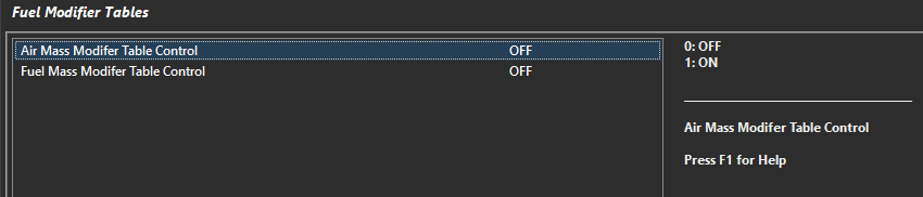
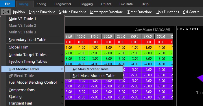
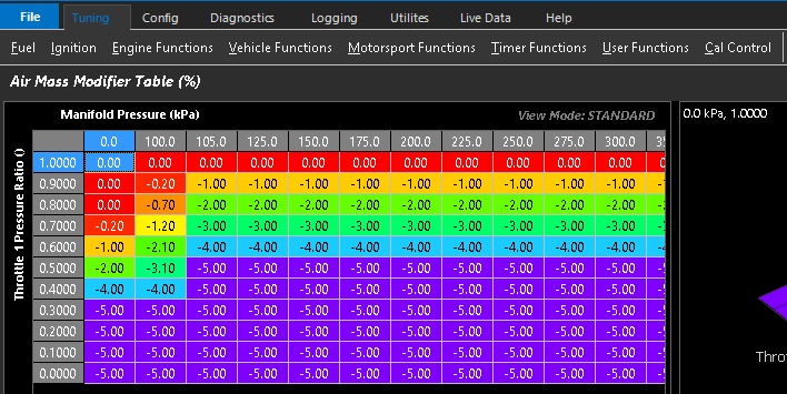
The Air Mass Modifier Table is enabled via Tuning -> Fuel Table Control -> Fuel Modifier Tables
Values in this table modify the ECUs Final Air Mass directly as a percentage
Bank Mass Air Flow Sensor
The ECU Independently controls the Fueling for the Engines Banks 1 and 2 using either two MAF Sensors . Required when there
is no common plenum between the cylinders banks.
Make sure the “Bank Cylinder Setup” Table is correctly initialised.
The Input “Mass Air Flow Meter 1” is used to control the Fueling on Bank 1.
The Input “Mass Air Flow Meter 2” is used to control the Fueling on Bank 2
Banked Speed Density
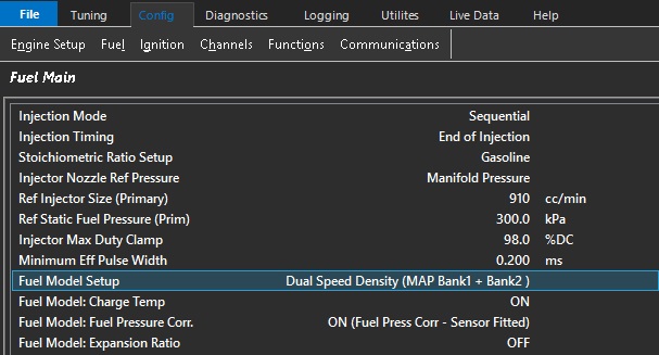
The ECU Independently controls the Fueling for the Engines Banks 1 and 2 using two MAP Sensors . Required when there is no common plenum between the cylinders banks.
Make sure the “Bank Cylinder Setup” Table is correctly initialised.
The Input channel “Manifold Pressure - Bank 1” is used to control the Fueling on Bank 1.
The Input channe; “Manifold Pressure - Bank 2” is used to control the Fueling on Bank 2.
Exhaust Pressure Estimate
For use when no Exhaust Pressure sensor is available.
Exhaust Pressure Estimate Setup
0: OFF
1: ON
Exhaust Pressure Estimate Table
3D table that with configurable axis to tune the Exhaust Pressure Estimate.
Units = kPa
Manifold Pressure Estimate
Generates a Manifold Pressure Estimate using a % Scaling table on the selected parameter.
Manifold Pressure Estimate Setup
0: OFF
Function is off
1: Table Value
Manifold Pressure Estimate Table = Raw Value
Table value = 50.8%
Manifold Pressure Estimate = 50.8 kPa (1:1)
2: % Barometric Pressure
Table value = 50.8%
Barometric Pressure = 96.8kPa
Manifold Pressure Estimate = 96.8kPa x 50.8% = 49.1kPa
3: % Manifold Pressure
Table value = 50.8%
Manifold Pressure = 96.8kPa
Manifold Pressure Estimate = 96.8kPa x 50.8% = 49.1kPa
4: % Manifold Pressure Bank 1/2 Average
Table value = 50.8%
Manifold Pressure Bank 1/2 Average = 96.8kPa
Manifold Pressure Estimate = 96.8kPa x 50.8% = 49.1kPa
5: % Boost Pressure
Table value = 50.8%
Boost Pressure = 253.6kPa
Manifold Pressure Estimate = 253.6kPa x 50.8% = 128.8kPa
6: % Boost Pressure Bank 1/2 Average
Table value = 50.8%
Boost Pressure Bank 1/2 Average = 253.6kPa
Manifold Pressure Estimate = 253.6kPa x 50.8% = 128.8kPa
Manifold Pressure Estimate Table
3D table that with configurable axis to tune the Manifold Pressure Estimate
Units = % and correspond to Manifold Pressure Estimate Setup parameter
Mass Air Flow Sensor (MAF) + AirMass Modelled (Blend)
A Blend Table generates a Final Air Mass using a ratio from the MAF Sensor and Air Mass Modelled.
The following MAF input channels can be used:
Mass Air Flow Sensor(s) 1 and 2
Mass Air Flow Bank Sensor(s) 1 and 2 can be used
The ECU will search which channel(s) are enabled and use those inputs. “Mass Air Flow Sensor” takes priority over “Mass Air Flow Bank Sensor”. For example if both
Mass Air Flow Sensor1 and Mass Air Flow Sensor2 input channels are configured the ECU will automatically use both inputs.
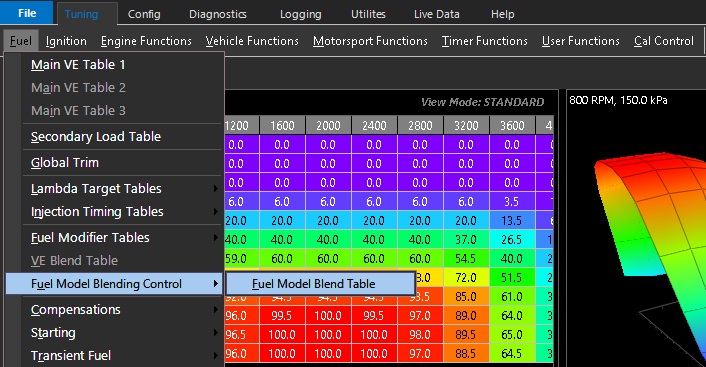
The fuel model blending control table is accessed from : Tuning -> Fuel -> Fuel Model Blending Control