Analog Channels 7-12 have configuration pull-up resistors. Sensors requiring a pull-up such as Engine Temperature or Inlet Temperature should use these channels.
There are two main groups of Input Setup Type - Analog Inputs and Digital Inputs. They are grouped into to standard form types, that are mostly the same for all inputs.
Analog Inputs
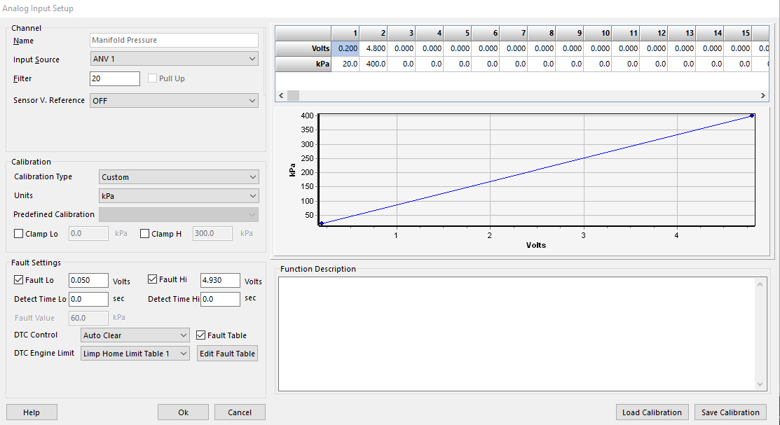
Above example shows Manifold Pressure Sensor channel.
Input Source
Choose your input source.
** See ECU Hardware Specifications for assigning the best source for your input channel
Filter
Each input can have its own moving average filter applied.
Pull Up
If the channel has pull up capability, the pull up flag will be available.
Sensor V. Reference
Select number of Analog Inputs have Ratio Metric input functions. Select the 5V V Reference Pin if applicable.
** See Ratio Metric Reference Manual available online
Calibration Type
Customize - via Multii-point table on the right
Pre-defined - Via dropdown list (Predefined Calibration)
Clamp Lo/H
Clamp the Low/High value of the input
Fault Lo/Hi
Set Low/High fault voltages
Detect Time Lo/Hi
Set Low/High detect time for fault values to be effective
Fault Value
Set the substitute value for each individual input when Fault is active
DTC Control
Set DTC (diagnostic trouble code) behavior
Auto Clear
Manual Clear (ECU must be connected to clear fault codes)
DTC Engine Limit
Set the Limp Home Limit Table to be used if DTC is active
Limp Home Table 1
Limp Home Table 2
Off
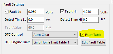
Fault Table
Some major sensor inputs (MAP, TPS, etc) have the ability to enable “Fault Table”, where in fault mode, substitute values can be more than one value.
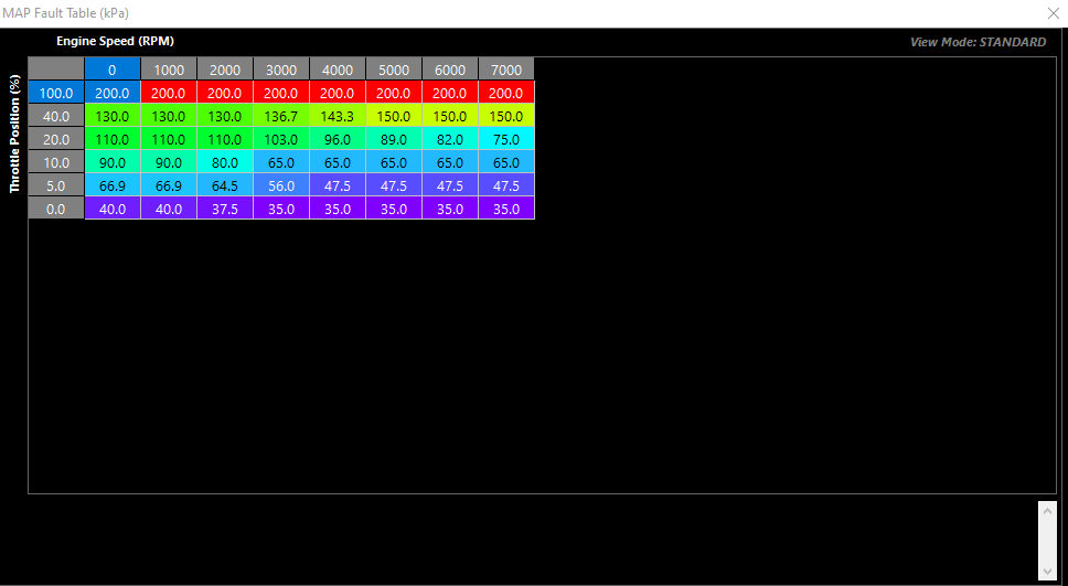
When enabling Fault Table, Fault Value becomes inactive. Clicking Edit Fault Table gives the user a larger table to add more than one value for substitute values
Axis for table is open, and as an example you can see for MAP substitute values, the axis is selected to look at TPS vs RPM
Digital Inputs
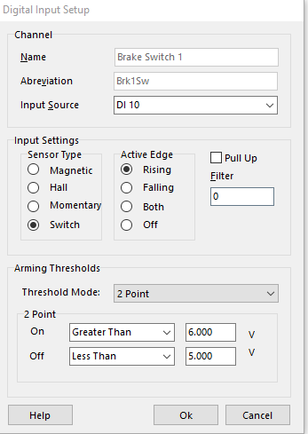
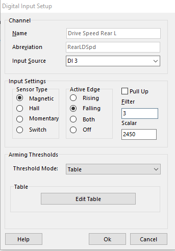
Above examples show a Brake Switch Input and wheel speed input
Input Source
Choose your input source.
** See ECU Hardware Specifications for assigning the best source for your input channel
Sensor Type
Select the Sensor Type
Magnetic
Hall
Momentary
Status will "latch" whenever the thresholds are satisfied
Switch
Will be active when the thresholds are satisfied
Active Edge
Rising
Falling
Both
Off
Pull Up
If the channel has pull up capability, the pull up flag will be available.
Filter
Filter value
Threshold Mode
2 Point
** Only to be used for switch inputs
Table
Table value dictates voltage crossover where signal is valid (voltage level must be **higher** than this arming voltage)
Used for frequency inputs
Active Edge must be configured correctly

See ECU Hardware Specifications for inputs with configurable table arming thresholds
2 Point On/Off
Voltages in which 2 Point mode thresholds are active
Hardware Specifications
Analog Inputs 1- 14
Input Analog Voltage Range: 0 - 5.0V
12 Bit ADC (4096 points)
1st order 100Hz Low pass filter.
1.22 mV (0.0122V) resolution.
DI 1- 8
Input Analog Voltage Range: 0 - 20.0V
4.88mV resolution (10 bit effective resolution using 20V Range - 1024 points)
Maximum usable analog input voltage: 20.0V
.
DI 9- 14
Input Analog Voltage Range: 0 - 20.0V
19.5 mV resolution (10 bit effective resolution using 20V Range) - 256 points
Maximum usable Analog Input Voltage: 20.0V
Example A. Take MAP sensor 0 - 5V input into the ECU with range of 0.0 kPa to 400.0 kPa (3 bar of boost)
a) Using AN 1- 14 (12 Bit resolution)
MAP Resolution = 400 kPa / 4096 = 0.097 kPa. This means the ECU can measure the pressure actuate to within 0.097 kPa using a 4Bar Map sensor.
b) Using DI 1- 8 (10 Bit resolution)
MAP Resolution = 400 kPa / 1024 = 0.488 kPa. This means the ECU can measure the pressure actuate to within 0.488 kPa using a 4Bar Map sensor.
c) Using DI 9- 14 (8 Bit resolution)
MAP Resolution = 400 kPa / 256 = 1.56 kPa. This means the ECU can measure the pressure actuate to within 1.56 kPa using a 4Bar Map sensor.
Example B. Take EGT 0- 5V input into the ECU with range of 0.0 DegC to 1000.0 DegC
a) Using AN 1- 14 (12 Bit resolution)
EGT Temperature Resolution = 1000 degC / 4096 = 0.24 degrees. This means the ECU can measure the EGT temperature actuate to within 0.24 degrees
b) Using DI 1- 8 (10 Bit resolution)
EGT Temperature Resolution = 1000 degC / 1024 = 0.98 degrees. This means the ECU can measure the EGT temperature actuate to within 0.98 degrees or 1.0 degrees rounded up.
c) Using DI 9- 14 (8 Bit resolution)
EGT Temperature Resolution = 1000 degC / 256 = 3.90 degrees. This means the ECU can measure the EGT temperature actuate to within 3.90 degrees or 4.0 degrees rounded up.
NOTE: The Digital Input voltage channels are normally used to read switch inputs and for ECU self testing procedures. However, DI1-8 channels still has very good resolution at 10 Bit with a 0 - 20V range so pressure and temperature sensors can still use connected to these channels.
Quick Calibrations
Quick Calibrations
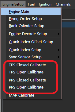
Config -> Engine Setup
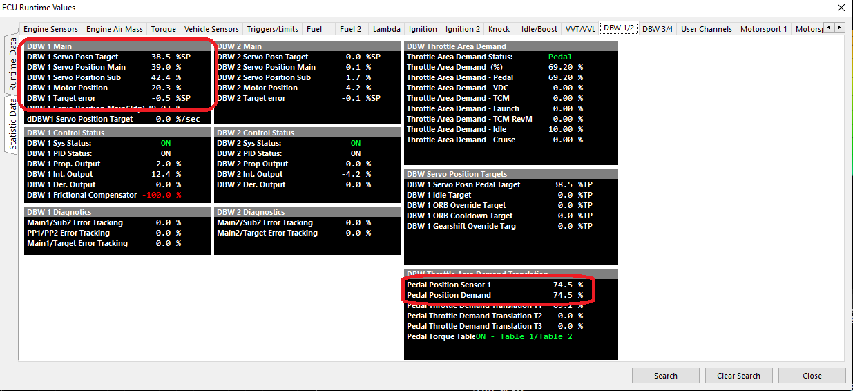
Calibrate Pedal (for DBW applications), and Throttle Position quickly from these menu choices
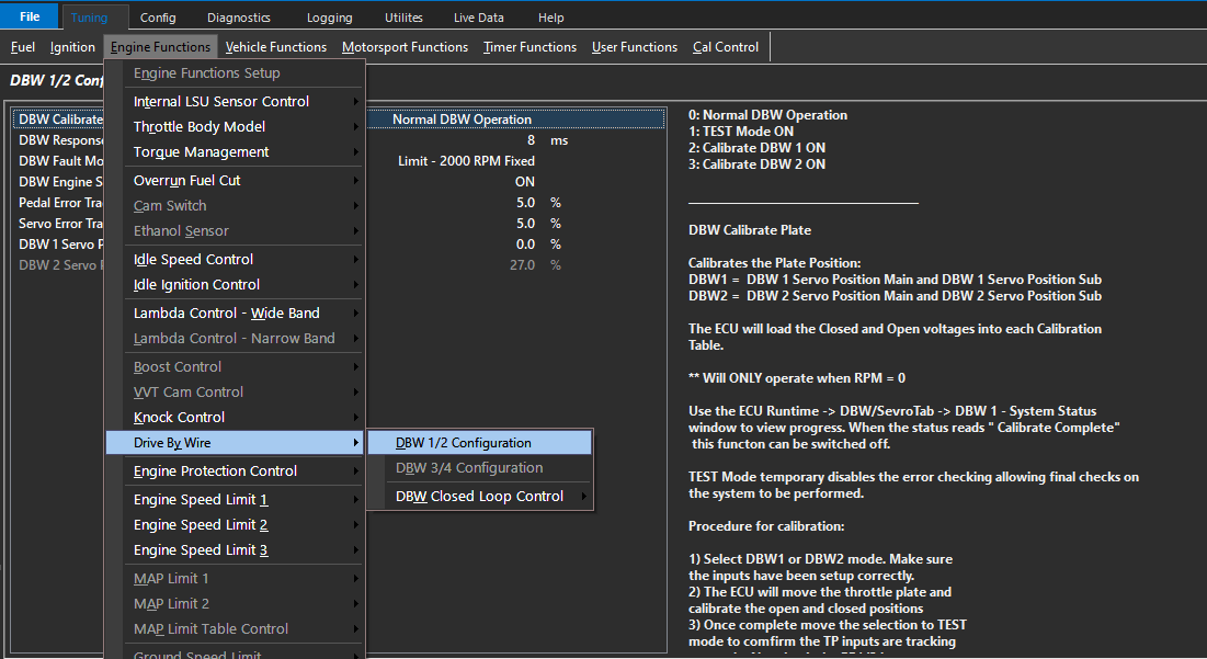
** To calibrate DBW plate position (with fully configured inputs/outputs), this is done in the Tuning Section, as generally the PID and other functions must be “tuned” as well - Tuning -> Engine Functions -> Drive By Wire -> DBW 1/2 Configuration
Changing DBW Calibration modes will calibrate the plate. See DBW specific help sections for more information.
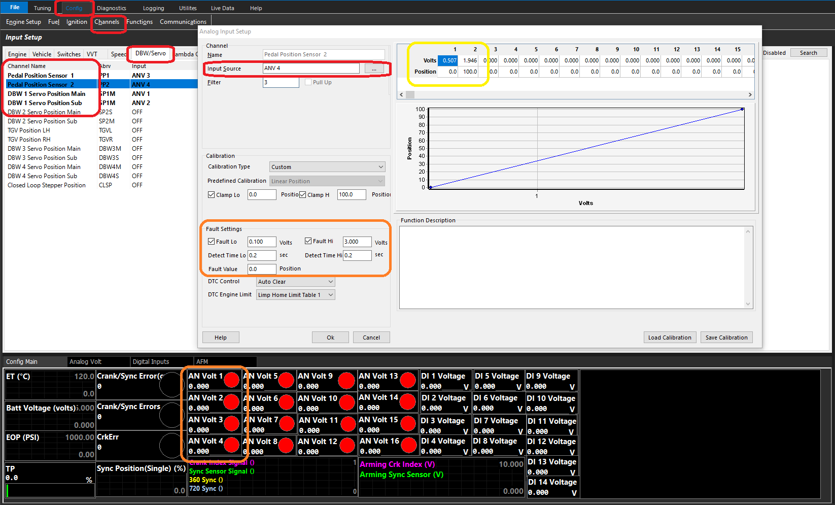
Validation of the programmed voltages can be observed under the input setup Config -> Channels -> Input Setup. Find the PP/DBW sensors under the DBW tab, or the TPS sensor under the Engine tab (depending which was calibrated), and you can validate if the programmed voltages are correct if there are any issues.
Make sure the fault settings are correct for swept voltages, and the raw voltages can even be viewed in the default view under the Config tab.
Voltages can also be viewed under F3 Runtimes under Raw Inputs, but also the calculated values can then be validated (Pedal Position %, DBW Servo, Throttle Position %).
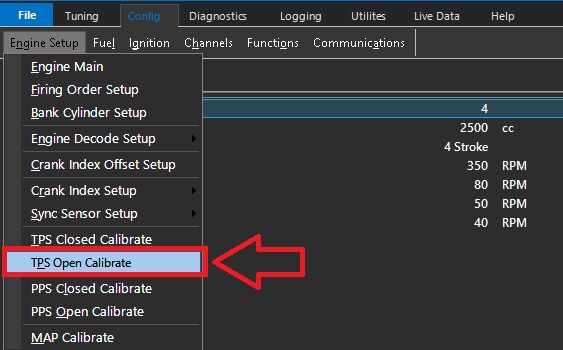
TPS Open Calibrate
This function is used to calibrate the Open position of the Throttle Position Sensor (TPS) for cable throttle systems
For DBW systems, the DBW servo position (main & sub) are calibrated in the DBW Setup
To utilise, Left mouse button click on tab (see above example)
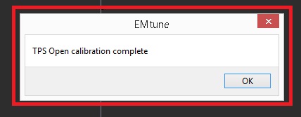
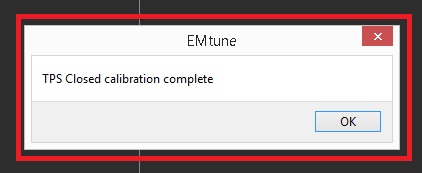
When completed, an acknowledgment tab will appear
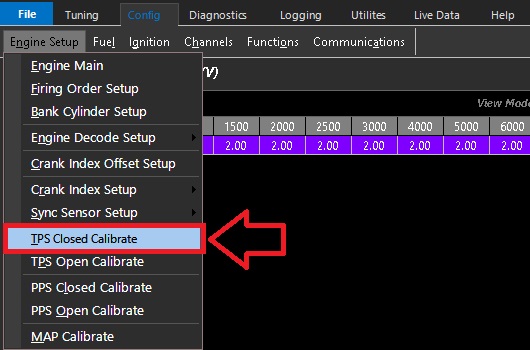
TPS Closed Calibrate
This function is used to calibrate the closed position of the Throttle Position Sensor (TPS) for cable throttle systems.
For DBW systems, the DBW servo position (main & sub) are calibrated in the DBW Setup
To utilise, Left mouse button click on tab (see above example)
When completed, an acknowledgment tab will appear
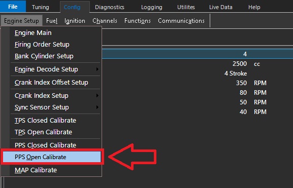
PPS Open Calibrate
This function is used to calibrate the Open position of the Pedal Position Sensor (DBW)
To utilise, Left mouse button click on tab (see above example)
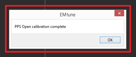
When completed, an acknowledgment tab will appear
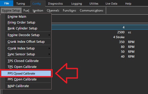
PPS Closed Calibrate
This function is used to calibrate the closed position of the Pedal Position Sensor (DBW)
To utilise, Left mouse button click on tab (see above example)
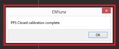
When completed, an acknowledgment tab will appear
Barometric Pressure
Filter Settings
FIlter Setting Minimum = 0 (OFF)
FIlter Setting Maximum = 50
Recommended Filter Range = 45
Calculated Runtimes
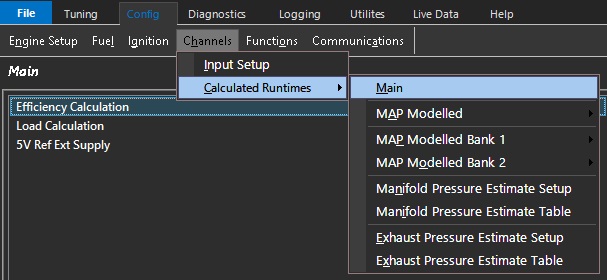
Main
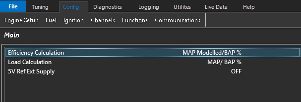
The Calculated runtimes Main is where the Efficiency Calculation and Load Calculation runtimes are defined.
The runtime is defined by nominating the air mass calculation and or blend to used to arrive at the runtime result
This permits the user to quickly utilize more complex forms of efficiency & load calculation
Both the efficiency & load calculation runtimes are labeled with a specific task in mind and also available as a selectable runtime for any table
Example:
In the KV sample file; note the main VE table load axis (Y axis) is configured as “Efficiency Calculation”, and the main ignition map is configured as “Load Calculation”
Efficiency Calculation
** Efficiency Calculation is used for Fuel Tables
Select how the runtime calculates Efficiency Calculation
0: MAP
Manifold Pressure converted to Efficiency Calculation %

MAP = 55.7kpa
Efficiency Calculation = 55.7%
1: TPS
Throttle Position converted to Efficiency Calculation %

TPS = 98.5%
Efficiency Calculation = 98.5%
2: BAP
Barometric Pressure converted to Efficiency Calculation %

BAP = 93.4kpa
Efficiency Calculation = 93.4%
3: MAP/BAP %
Manifold Pressure divided by Barometric Pressure converted to Efficiency Calculation %
MAP = 85kpa
BAP = 87kpa
Efficiency Calculation = (85/87)*100 = 97.70%
4: MAP/EMAP %
Manifold Pressure divided by Barometric Pressure converted to Efficiency Calculation %
MAP = 220kpa
EMAP = 240kpa
Efficiency Calculation = (220/240)*100 = 91.66%
5: TPS/BAP %
Throttle Position divided by Barometric pressure converted to Efficiency Calculation %
TPS = 98%
BAP = 85kpa
Efficiency Calculation = (98/85)*100 = 115.29%
6: Air Mas Final (mg/cyl)
Air Mass milligrams per cycle converted to Efficiency Calculation %


Air Mass = 0.121g/cyl

Efficiency Calculation = 0.121*1000 = 121%


Air Mass = 1.373g/cyl

Efficiency Calculation = 1.373*1000 = 1373%
7: MAP Bank 1 & 2 Avg
Manifold Pressure Bank 1 and 2 averaged together converted to Efficiency Calculation %

MAP Bank 1 = 224kpa

MAP Bank 2 = 236kpa

Efficiency Calculation = 224+236/2 = 230%
Select how the runtime calculates Load Calculation
0: MAP
Manifold Pressure converted to Load Calculation %

MAP = 55.7kpa
Load Calculation = 55.7%
1: TPS
Throttle Position converted to Load Calculation %

TPS = 98.5%
Load Calculation = 98.5%
2: BAP
Barometric Pressure converted to Load Calculation %

BAP = 93.4kpa
Load Calculation = 93.4%
3: MAP/BAP %
Manifold Pressure divided by Barometric Pressure converted to Load Calculation %
MAP = 85kpa
BAP = 87kpa
Load Calculation = (85/87)*100 = 97.70%
4: MAP/EMAP %
Manifold Pressure divided by Barometric Pressure converted to Load Calculation %
MAP = 220kpa
EMAP = 240kpa
Load Calculation = (220/240)*100 = 91.66%
5: TPS/BAP %
Throttle Position divided by Barometric pressure converted to Load Calculation %
TPS = 98%
BAP = 85kpa
Load Calculation = (98/85)*100 = 115.29%
6: Air Mas Final (mg/cyl)
Air Mass milligrams per cycle converted to Load Calculation %


Air Mass = 0.121g/cyl

Load Calculation = 0.121*1000 = 121%


Air Mass = 1.373g/cyl

Load Calculation = 1.373*1000 = 1373%
7: MAP Bank 1 & 2 Avg
Load Pressure Bank 1 and 2 averaged together converted to Load Calculation %

MAP Bank 1 = 224kpa

MAP Bank 2 = 236kpa

Load Calculation = 224+236/2 = 230%
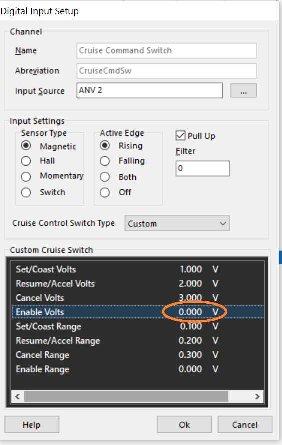
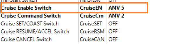
When the Voltage setting = 0.0V the corresponding setting is disabled within the Cruise Command Switch channel. In the below example the “Enable Sw” setting is disabled.
As the Enable Sw is disabled within the “Cruise Command Switch” channel in the above example, it allows the dedicated “Cruise Enable Switch” channel to be used.
Engine Oil Pressure
Filter Settings
FIlter Setting Minimum = 0 (OFF)
FIlter Setting Maximum = 50
Recommended Filter Range = 35 - 40
Engine Oil Temperature
This sensor should use Analog Input Channels 7 -12 as these have configurable pull-up resistors.
Filter Settings
FIlter Setting Minimum = 0 (OFF)
FIlter Setting Maximum = 50
Recommended Filter Range = 35 - 40
Engine Temperature
This sensor should use Analog Input Channels 7 -12 as these have configurable pull-up resistors. Recommended channel for Engine Temperature is Analog Input Channel 7.
Filter Settings
FIlter Setting Minimum = 0 (OFF)
FIlter Setting Maximum = 50
Recommended Filter Range = 40 - 45
Specs
Minimum Value = -50.0 DegC
Maximum Value = 250.0 DegC
Resolution = 0.1 DegC
Accuracy = +/-0.5 DegC
The ECU measures the 5V pull-up supply, then applies a ratio-metric correction to give very accurate measurements.
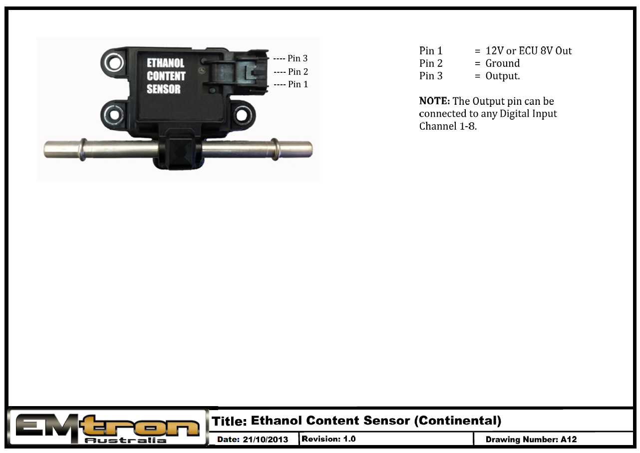
Ethanol Content Sensor - Continental
Exhaust Manifold Pressure
![IMPORTANT] Only absolute pressure sensors can be used. Gauge type sensors will NOT work as an EMAP sensor.
Filter Settings
FIlter Setting Minimum = 0 (OFF)
FIlter Setting Maximum = 50
Recommended Filter Range = 35 - 40
Fuel Pressure 1
Filter Settings
FIlter Setting Minimum = 0 (OFF)
FIlter Setting Maximum = 50
Recommended Filter Range = 20 - 25
Fuel Temperature
This sensor should use Analog Input Channels 7 -12 as these have configurable pull-up resistors.
Filter Settings
FIlter Setting Minimum = 0 (OFF)
FIlter Setting Maximum = 50
Recommended Filter Range = 35 - 40
Inlet Air Temperature
This sensor should use Analog Input Channels 7 -12 as these have configurable pull-up resistors. Recommended channel for Inlet Temperature is Analog Input Channel 8.
Filter Settings
FIlter Setting Minimum = 0 (OFF)
FIlter Setting Maximum = 50
Recommended Filter Range = 10 - 15
Input Shaft Speed
Input Shaft Speed is available on Channels DI 1- 8 on the KV Series and DI1-4 on the SL Series. The units are RPM.
With 0% Clutch Slip, for the Input Shaft RPM to match the Engine Speed the Scaler should be calculated as follows:
Scaler = 60
Number teeth on Input Shaft
Example1: 4 teeth on the Input Shaft
Scaler = 60 / 4 = 15.00
Example1: 7 teeth on the Input Shaft
Scaler = 60 / 7 = 8.57
Intake MAF Air Temperature
This sensor should use Analog Input Channels 7 -12 as these have configurable pull-up resistors.
Filter Settings
FIlter Setting Minimum = 0 (OFF)
FIlter Setting Maximum = 50
Recommended Filter Range = 35 - 40
Internal LSU Sensor Control
Internal LSU Sensor Control
The KV series ECU has the ability to interface directly to a Bosch Lambda Sensor(s), model LSU4.9.
To achieve the optimal control of this sensor, the ECU uses a genuine Bosch Integrated Circuit technology. It provides very accurate data on pump current which equates to Lambda
and also Nernst Cell Temperature which is used for precise heater control.
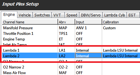
The ECU assigns the correct the Heater Output Channel based on ECU Type and Serial Number. The only setup required to enable the Internal Lambda 1 or 2 control is from the Config View -> Inputs-> Engine tab.
If “Lambda 1” Input Channel has the Input Source selected to “Internal Lambda 1” the function becomes enabled.
If “Lambda 2” Input Channel has the Input Source selected to “Internal Lambda 2” the function becomes enabled
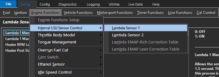
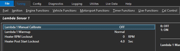
Adjustments to the operation of On-board Lambda Sensor Control can be made from the Tuning view -> Engine Functions -> Internal LSU Sensor Control
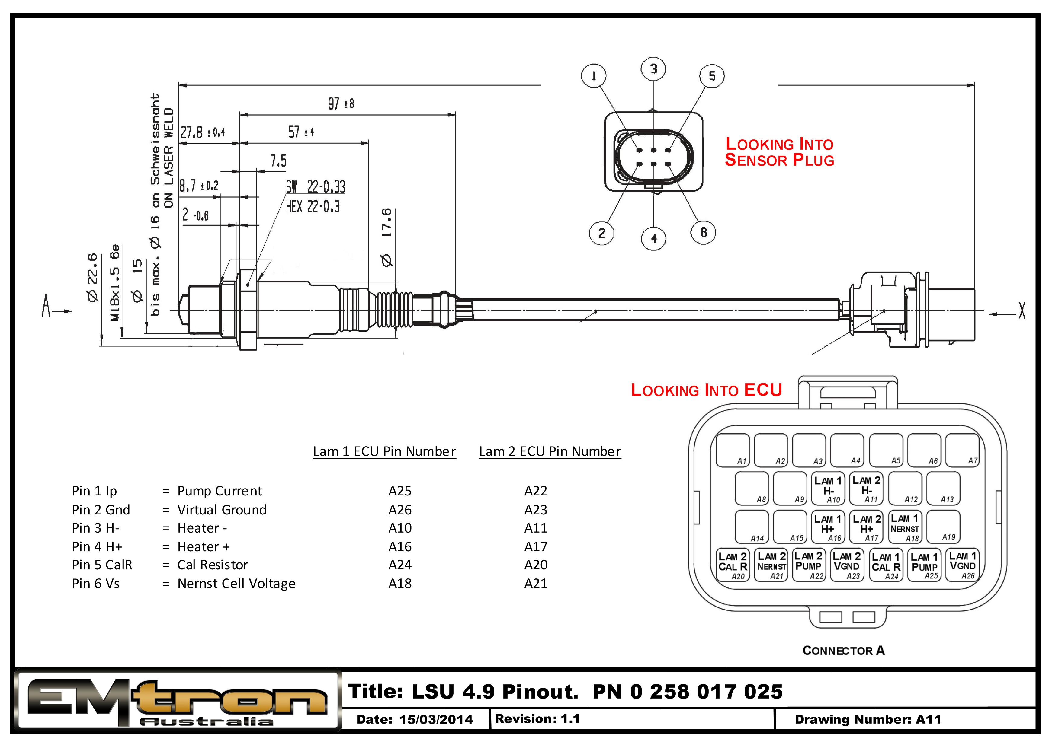
The ECU uses all 6 sensor wires per sensor.
Sensor Shock
In some situations during normal operation, the sensor will temporally shutdown for between 0.5 sec to 2.5 secs. This is usually caused by a combination of sensor incorrect placement and Fuel type resulting in the sensor being “shocked” ; either thermally or by a pressure wave inside the exhaust system. For the correct sensor placement please read the Sensor Installation and Wiring topic.
Although the sensor shutdown is outside the ECU’s control, the status is constantly monitored. In the event of a shutdown the heater control is put into a Hold mode as it the Closed Loop Lambda.
Lambda Inputs
Filter Settings
FIlter Setting Minimum = 0 (OFF)
FIlter Setting Maximum = 50
Recommended Filter Range = 15 - 20
Lambda Sensor Installation and Wiring
Sensor Installation
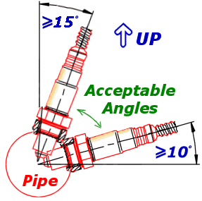
Installation angle must be inclined at least 10° towards horizontal, (electrical connection upwards) up to a maximum of 75°. This prevents the collection of liquids between sensor housing and sensor element during the cold start phase.
The angle against the exhaust gas stream should be aimed as 90°. Maximum inclination should be 90°+15° (protection tube towards gas stream) or 90°-30°.
NOTE: NEVER mount the sensor directly on the horizontal or within 10 degrees of the horizontal. Doing so will result in intermittent sensor shutdown.
Also route the sensor cable to avoid high moisture locations – just a small amount of moisture is enough to provide a conductive path within the connector that will upset measurement from the sensor.
Winter and salted roads compound this issue. Always check for a cracked or broken connector when strange results occur.
Noise Immunity
To minimize signal contamination and maximize noise immunity, the wire pairs shown in the below Table must be twisted. It is recommended to twist the wire pairs at a minimum one twist per 40mm of cable. This is very important and should always be implemented on the LSU sensor wiring.
Pair 1
Pair 2
Pump Current
<——->
Cal Resistor
Nernst Cell Voltage
<——->
Virtual Ground
Wire pairing for twisting
NOTE: To avoid signal errors and loss of accuracy, a cable of a maximum length of 1.5 m between sensor and ECU is recommended.
LSU 4.9 ADV / LSU 4.9 Comparison
Difference between LSU4.9 ADV and LSU 4.9
Heater Power and Light-Off Times: The LSU4.9 Adv has a bigger heater element allowing the sensor to start operating sooner when compared to a LSU4.9:
LSU4.9 ADV has a 8.7W heater - 5sec lite-off time from cold to start operating
LSU4.9 has a 7.5W heater - 12sec lite-off time from cold to start operating
Temperature Range: The LSU4.9 ADV has a wider working temperature range (930DegC). A version of this sensor called the ”LSU 4.9 Adv pre-Turbo” is also available and has a protection tube of Inconel for pre-turbo applications.
Sensor Element: LSU4.9 ADV has a new generation sensor element which is ideal for motorsport as it improves stability under thermal shock conditions.
Service Life - 200Hrs Example
LSU4.9 response time will slow over time.
LSU4.9 ADV response time will show no significant change over this time.
Connector: The LSU 4.9 Adv has no trimming resistor inside the connector (pin 5) and is therefore only a 5-wire plug. This also means any connector system can be used if required (cut off the connector and re-terminate).
Manifold Pressure
Manifold Pressure Input
Filter Settings
FIlter Setting Minimum = 0 (OFF)
FIlter Setting Maximum = 50
Recommended Filter Range = 15 - 25. This setting is heavily dependent on engine setup and the stability of the MAP signal at idle. Engines with large overlapping camshafts for example, will most likely need a larger filter value to achieve a more stable MAP signal.
Specs
Minimum Value = 0.0 kPa
Maximum Value = 1000.0 kPa
Resolution = 0.1 kPa
Accuracy = +/-0.1 kPa
The ECU measures the MAP Sensor Supply, then applies a ratio-metric correction to give a very accurate measuremens. What this means is the MAP sensor output is not affected but its supply voltage.
Speed Inputs
Normally these are frequency based inputs and should be connected between Digital Input 1 - 8. The ECU can can read a frequency range on these input from 0Hz - 25kHz (25000Hz).
The following Speed Options are available:
Left Drive Speed.
Right Drive Speed
Left Drive Speed 2
Left Drive Speed 2
Left Ground Speed
Right Ground Speed
Drive Speed
Ground Speed
Turbo Speed 1
Turbo Speed 2
Input Shaft Speed
Tail Shaft Speed
Sources
The following channel assigns are recommended.
Four Wheel Drive
If the speed data is collected by the ECU on all 4 wheels, then assign the front wheels to the Left and Right Drive Speed Channels and the rear wheels to the Left an Right Speed 2 Channels
Gearbox Output
Assign this to the Drive Speed Channel.
CAN
CAN Data: Input Source = CAN Bus OEM
This allows speed data that is available on a factory CAN bus to be displayed. The following channels can be used for different CAN bus systems.
NOTE: When the Input Source is selected as “CAN Bus OEM” only the Filter setting is used. All other settings are not required as the data is already calibrated.
See Build Packages for application specific information.
Configuration
Each Speed Input has a range of settings that must to be configured to match the input type.
Sensor Type
Magnetic.
Hall Effect
Logic
Switch.
Active Edge
Rising
Falling
Both
Off
Pull Up
Can be used to switch on a 9V pull up resistor.
Scaler
Scales the frequency based input into kph or into the units that have been selected. The raw frequency value can be viewed from the Runtime Menu -> Raw Inputs Tab.
Arming Thresholds
Each channel when assigned between DI 1-8 can have two options for arming threshold control; 2 point or Table.
NOTE: It is recommended on ALL frequency based Magnetic inputs that the Table option is used. This allows better signal integrity control due to the improved functionality offered by the table.
Scaler Calculation
Scaler = Number of Sensor Teeth / Wheel Diameter(cm) * 3180
Scaler = 360 when using CAN Speed Inputs
Throttle Position
Used primarily by the ECU for Transient Accel and Decel fueling. It can be used in 4D/5D mapping and also controls the lockout conditions for many ECU functions.
Clamp Settings
The available range is from -100.0 % to 100.0%, however after calibration the range should show 0.0%(closed throttle) to 100.0%(open throttle).
NOTE: The ECU does not clamp the minimum TP to 0.0% nor the maximum to 100.0%. These settings are adjustable from the Input Setup Form.
Clamp Lo
Recommended value = -10.0%.
Clamp Hi
Recommended value = 105.0%.
Filter Settings
FIlter Setting Minimum = 0 (OFF)
FIlter Setting Maximum = 50
Recommended Filter Range = 2 - 5
Specs
Minimum Value = -100.0 %
Maximum Value = 100.0 %
Resolution = 0.1 %
Accuracy = +/-0.1 %
In DBW Applications also refer to DBW Input Setup
Turbo Speed
Turbo Speed is available on Channels DI 1- 8 on KV Series and DI1-4 on SL Series.
The units are RPM
Tip: See Speed Inputs for information on sensor setup.
Turbo Speed Calculation
Turbo Speed(RPM) = Frequency x Scaler x 10
Example: 2351 Hz, Scaler = 2.56
Turbo Speed = (2351 Hz x 2.56) x 10 = 60180 RPM
Example: 4436 Hz, Scaler = 2.56
Turbo Speed = (4436 Hz x 2.56) x 10 = 113560 RPM
Note: Turbo speed sensor electronics divide the raw frequency by 8
Scaler
Turbo Fin Count: 14
Electronics Divider : 8
Turbo Speed : 100,000
Convert Pulse to Frequency : /60
(100000 / 8) x 14 / 60 = 2916.67 Hz
Resolution Modifier : 10
2916.67 x 10 = 29166.7
Scaler = 10000 / 29166.7 = 3.43
VVT
VVT Input Channel Selection
For closed loop position control, each camshaft must be assigned a position sensor. \
Config View -> Inputs -> Input Pin Setup -> VVT
Example Config (quad cam VVT control):
Configure sensor inputs as required. Magnetic, Hall, DI threshold table, etc.
******* Since one Cam position sensor is being used for sync, select which camshaft should reference the Sync Sensor for position – IE Intake (LH). ***