The ECU has 2 independent CAN Nodes.; CAN 1 and CAN 2. The Baud rate can be independently set for each node.
The ECU has 128 message boxes. This means the ECU can Receive or Transmits on 128 different Addresses. This is a very large number and offers great flexibility. In order the simply setup procedure the CAN 1 and CAN 2 will be separated into Channels, with each Channel having a fixed number of available messages boxes/addresses.
CAN Termination
The ECU does not include an internal 120ohm CAN terminating resistor. This allows the ECU to be placed at any location within the CAN bus system.
If the ECU is located at the end of the CAN bus, an external 120 ohm terminating resistor will need to be used.
CAN Nodes
CAN 1
CAN 1 node is divided up into 6 Channels, 64 message objects in total
MO = Message Object
CAN 1 Channel Number
Number of Message
CAN 1 - Channel 1
14 CAN message objects
CAN 1 - Channel 2
10 CAN message objects
CAN 1 - Channel 3
10 CAN message objects
CAN 1 - Channel 4
10 CAN message objects
CAN 1 - Channel 5
10 CAN message objects
CAN 1 - Channel 6
10 CAN message objects
CAN 2
CAN 2 node is divided up into 6 Channels, 64 message objects in total
CAN 1 Channel Number
Number of Message
CAN 2 - Channel 1
14 CAN message objects
CAN 2 - Channel 2
10 CAN message objects
CAN 2 - Channel 3
10 CAN message objects
CAN 2 - Channel 4
10 CAN message objects
CAN 2 - Channel 5
10 CAN message objects
CAN 2 - Channel 6
10 CAN message objects
Addressing
0: Single (11-BIT)
1: Sequential (11-BIT)
2: Single (29-BIT)
3: Sequential 29-BIT)
Base Address
Starting CAN Address / PID (Parameter ID).
The CAN Base Address tells the ECU where to start transmitting data from.
These values are in DECIMAL, not hex.
Single
Only the single “CAN Address” is active.
This means data can only be TX/RX on that single CAN Base Address
Sequential
The CAN address starts at the “CAN Address” defined then sequentially increments that address until all the data has been transmitted
Once the data (TX/RX) on the CAN Base Address is full, the ECU will poll the next address sequentially for additional data
IE 1250, 1251, 1252, …
Bandwidth Considerations
Bus bandwidth needs to be considered when data is transmitted over CAN. The ECU has Transmit rates from 10Hz up to 1000Hz.
Example 1:
The following uses the Predefined 1 Tx DATA set. This uses 10 sequential addresses and it total transmits the value of 40 parameters. CAN Baud rate at 1Mbps
Tx Rate
Number of Messages
Bandwidth Used (%)
Available Bandwidth for other devices
10Hz
10
1.2%
98.8%
50Hz
10
6.1%
93.9%
100Hz
10
12.2%
87.8%
500Hz
10
61%
39%
1000Hz
10
Cannot be achieved
Example 2:
The following uses the Custom 1 Tx DATA set. This uses 5 sequential addresses and it total transmits the value of 20 parameters. CAN Baud rate at 1Mbps
Tx Rate
Number of Messages
Bandwidth Used (%)
Available Bandwidth for other devices
10Hz
5
0.6%
99.4%
50Hz
5
3.05%
96.95%
100Hz
5
6.1%
93.9%
500Hz
5
30.5%
69.5%
1000Hz
5
61%
39%
OBD II J1979
Onboard Diagnostics 2 or OBD2 is supported by the ECU using the SAE J1979 standard. The ECU supports the following service requests:
Show current data
Mil Status
Show stored Diagnostic Trouble Codes (DTCs)
Clear Diagnostic Trouble Codes (DTC) and stored values
Request vehicle information
OBD II Service Mode 01 - Show Current Data
The ECU supports the following PIDs when the “Show Current Data” serviced is requested.
PID(hex)
PID(Dec)
Data bytes returned
Description
Min value
Max value
Units
Notes
01
1
4
Monitor status since DTCs cleared. (Includes malfunction indicator lamp (MIL) status and number of DTCs.)
03
3
2
Fuel system status
Only displayed when Closed Loop Fuel enabled. See Below
Closed loop, using oxygen sensor feedback to determine fuel mix
4
OPEN1
Open loop due to lockout condition or OFF (fuel cut due to deceleration, limiting, post start etc)
8
OPEN 2
Open loop due to system failure
16
CLSD1
Closed loop, using at least one oxygen sensor but there is a fault in the feedback system
PID 0x04 - Calculated Engine Load
There are 2 types of load defined by the SAE J1979, one is Calculated engine load the other Absolute engine load. The Calculated Load is referenced to engine speed, so its the %Engine Load at that RPM.
As defined by ODB II regulations Calculated load = (Current airflow / peak airflow @sea level) x (Baro @sea level / Baro) x 100%
PID 0x1C - OBD standards this vehicle conforms to
A request for this PID returns a single byte of data which describes which OBD standards this ECU was designed to comply with. Emtron replies with a value of 6
| 3 | OBD and OBD-II |
| 4 | OBD-I |
| 5 | Not OBD compliant |
| 6 | EOBD (Europe) |
| 7 | EOBD and OBD-II |
| 8 | EOBD and OBD |
| 9 | EOBD, OBD and OBD II |
| 10 | JOBD (Japan) |
| 11 | JOBD and OBD II |
| 12 | JOBD and EOBD |
| 13 | JOBD, EOBD, and OBD II |
| 14 | Reserved |
| 15 | Reserved |
| 16 | Reserved |
CAN Bus Errors
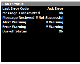
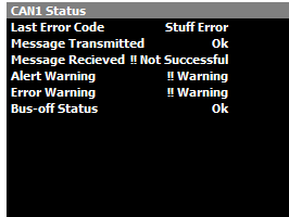
CAN Diagnostics information can be found under the Communications Tab in the Runtime (F3) menu.
Last Error Code Status
Ack Error. This normally indicates the ECU cannot communicate with other devices on the BUS. Check all devices are running the same BUS Baud rate.
BIT 0 Error. If this error is constant, it normally indicates a direct short between CAN Lo and CAN Hi.
BIT 1 Error. If this error is constant, it normally indicates a direct short between CAN Lo and CAN Hi.
BIT 0 & Ack Error. If the error is toggling between these two messages, this normally indicates the CAN Lo and CAN Hi are reversed.
Command Bus Errors
Emtron Transmitting data , but receiving device is missing from the CAN Bus.
Emtron Transmitting data , but receiving device is missing from the CAN Bus and 120 Ohm terminating resistor missing.
CAN Bus Termination
CAN Bus High and Low are differential signals, so twisted pair MUST be used. Failing to do so will compromise the entire CAN Bus System.
Shielded twisted pair may be required to help with reliability and data integrity.
The less connectors in any transmission system the better. Unnecessary connectors are almost guaranteed to present an impedance discontinuity and hence may cause reflections and data loss.
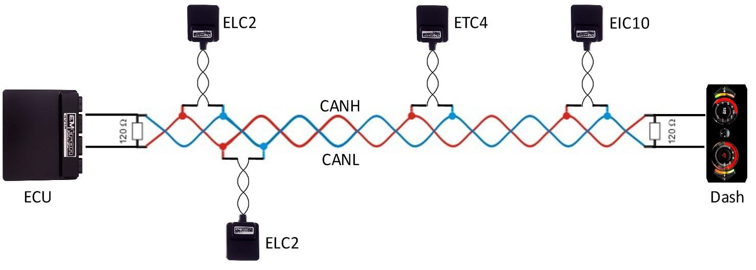
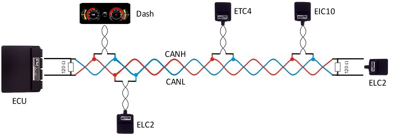
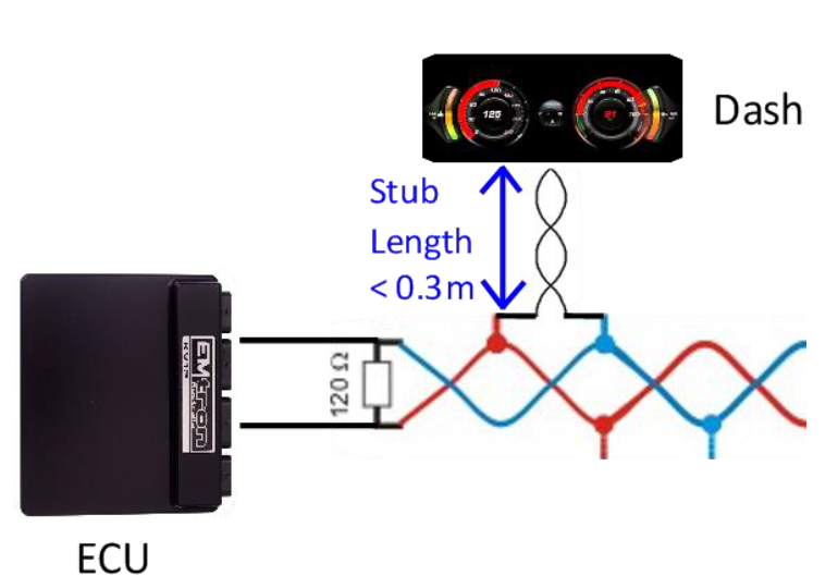
CAN Bus termination must be done correctly by using a 120 ohm 0.25W resistor at each END of the bus system.
Maximum Stub length to a device from the main Bus is recommended at 0.3m, in accordance with High-Speed ISO 11898 Standard specification. See Figure 3.3.
The ELC devices do not include an on-board CAN termination resistor, allowing the device to be wired at any position on the Bus. CAN Bus termination must be done correctly by using a 120 ohm 0.25W resistor at each end of the bus system as mentioned above. Figures 3.1 and 3.2 show possible CAN Bus Implementation examples
Figure 3.1. CAN Bus Wiring Example. ECU and Dash at each end with 120 Ohm Termination
CAN Bus Wiring Example
ECU and ELC2 at each end with 120 Ohm Termination.
Stub Length less than 0.3m
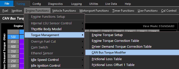
CAN Bus Torque Modifier
CAN Bus Torque Modifier
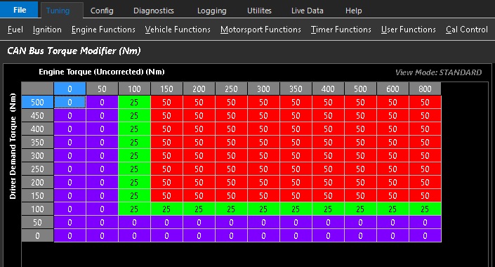
This table is used to modify the torque calculation to be delivered as an output for use on an OEM Can Bus or other CAN bus applications. The Torque value can be “bent” allowing the user to change the behavior of a vehicle system e.g Traction or Gearshift . This gets applied as an offset to both the Engine Torque and Driver Demand Torque. Table range is +/- 500Nm.
The default table is a single cell without axis. However, both the X & Y axis are available and can be enabled at any time in the axis setup form.
CAN Custom RX Data Sets
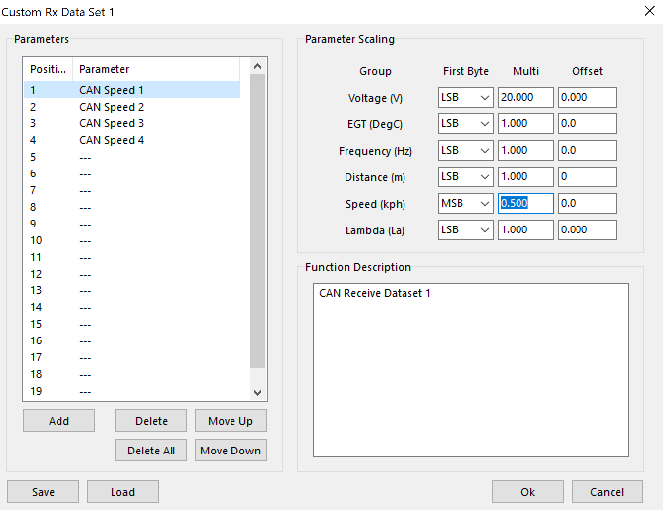
Emtron can be configured to receive Custom Messages over CAN bus channels.
To Receive the Custom RX Data sets, select them under
Config -> Communications -> CAN Bus 1/2 -> DATA Set
** Scaling per data set will be fixed. IE - CAN Speed for Data Set 1 must all be the same
** Channels received are raw CAN runtimes. These channels must be assigned to “real” runtimes to be used in different sections of the ECU.
CAN Parameter Scaling
Info
All values are 16 bit unsigned intergers, LSB Byte Order
InfoUnlisted runtimes are raw
Type
Multiplier
Offset
Unit
Lambda
0.001
0
Lambda
Lambda Target Error
0.001
-10
Lambda
STFT/LTFT
0.01
-100
%
Cam Position
0.1
-200
Degree
MGP
0.1
-100
KPA
Fuel/Oil Pressure
0.1
0
KPA
PPS/TPS/Motor Position
0.1
-100
%
VE
0.1
0
%
IdleP
0.1
0
%
PP/TP Error
0.1
0
%
DBW Target Error
0.1
-100
%
Injector duty
0.1
0
%
Inj PW
0.001
0
ms
F/I Cut
0.1
0
%
Speed KPH
0.1
0
KPH
RPM ROC
1
-20000
RPM/second
PP/TP ROC
0.1
-100
%/second
ECU G
0.01
-10
G
Ignition angle
0.1
-100
Degree
Ignition trims
0.1
-100
Degree
FP Diff Offset
0.1
-1000
KPA
Voltage
0.001
0
Voltage
Drive Slip
0.01
-100
%
Temps
0.1
-50
Degrees C
Fuel Level
0.1
0
Liters
Fuel used
0.01
0
Liters
Gear
1
-10
Gear
Time Milliseconds
0.01
0
Milliseconds
Time Seconds
0.1
0
Seconds
Time Min
1
0
Min
Force
0.1
-100
KG
Mass flow /Sec
0.1
0
G/s
Mass flow /Cyl
0.001
0
G/cyl
Traction Target
0.1
0
%
Traction Target Error
0.1
-100
%
Power
1
0
KW
Torque
1
-1000
NM
Torque Reduction (Frictional loss)
-1
0
NM
Vehicle Accel (M/S/S)
0.01
-100
m/s/s
Vehicle Accel (KM/HR/S)
0.01
-100
km/hr/s
CAN Torque Limit
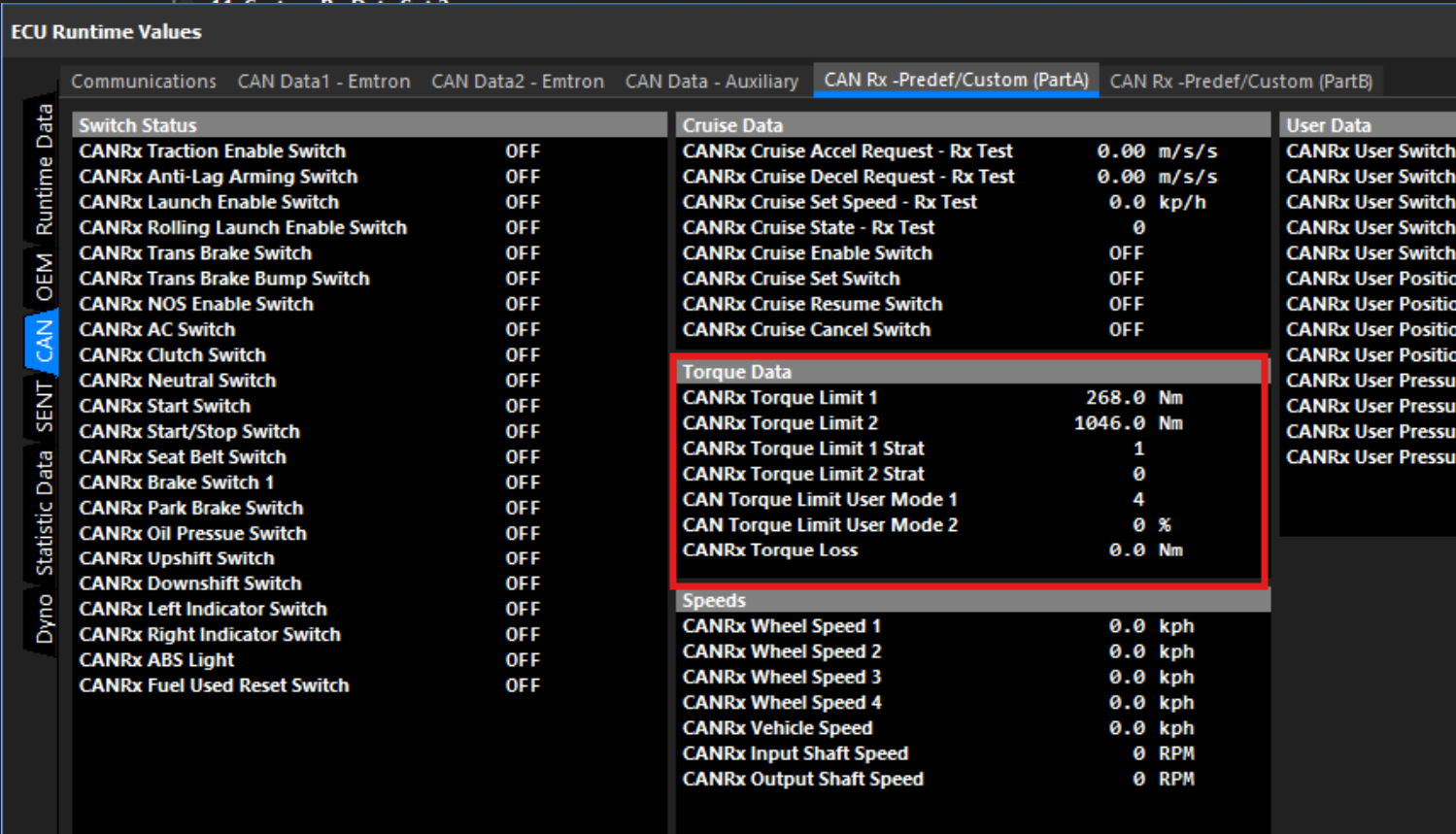
The ECU can receive Torque Limit Request(s) over the CAN Bus.
ImportantThis is available on firmware 2.20.0 or later.
The torque limit frame can be received from 3 different data sets. If more than one are received they are used with the following priority:
Emtron CAN Torque Limit (ID 1428).
Advanced Rx Data Set 1
Pre-defined Rx Set 1 v0.1 - Message 5 (ID 1428).
InfoThis is an Absolute Engine Torque Limit Request. Eg: If 350.0Nm is requested the Torque Limiting function will target 350.0Nm from the engine.
The frame contains 2 torque limits, the lowest one will be applied (assuming it’s the lowest of all other active torque limits).
CAN Rx ID: 1428 (0x594)
Signal
Start Bit
Length
Factor
Offset
Note
CAN Torque Limit 1 (NM)
0
16
0.1
-500
Absolute engine torque limit. -500 = Off.
CAN Torque Limit 2 (NM)
16
16
0.1
-500
Absolute engine torque limit. -500 = Off.
CAN Torque Limit 1 Strat Select
32
4
1
0
Selects the torque limit strategy used to apply the torque limit.
CAN Torque Limit 2 Strat Select
36
4
1
0
Selects the torque limit strategy used to apply the torque limit.
CAN Torque Limit 1 User Mode
40
4
1
0
Can be used to span a table axis. Values of 0-15.
CAN Torque Limit 2 User Mode
44
4
1
0
Can be used to span a table axis. Values of 0-15.
CAN Torque Loss
48
10
1
0
Applies a reduction to the ECU’s Uncorrected Torque calculation. Can be used to account for drive train losses. Should always be 0 unless you have very good reason to change it!
Note: All data is Unsigned, Little Endian (LSB First) format.
Example
Example CAN Channel Setup:
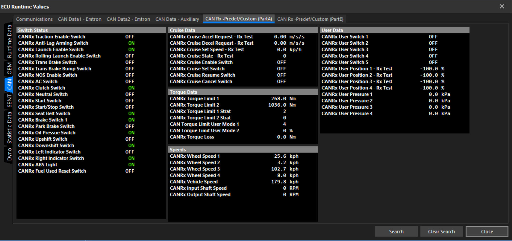
Received raw data can be viewed in the F3 window on the CAN Tab.
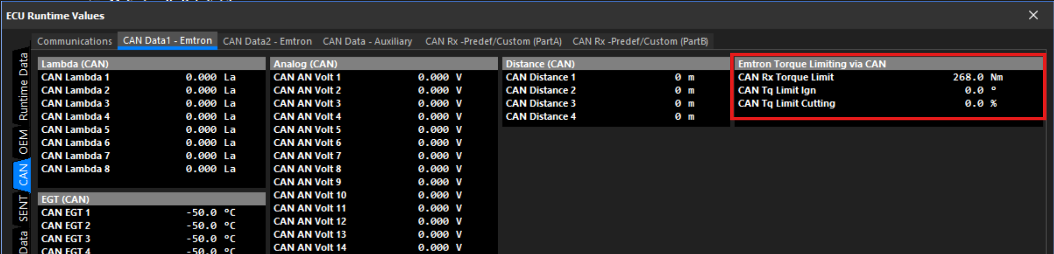
Final CAN Torque limit result is shown here:
The CAN Torque Limit User Mode 1 & 2 values are available to be used anywhere in the ECU as table axis’ or inputs to user functions.
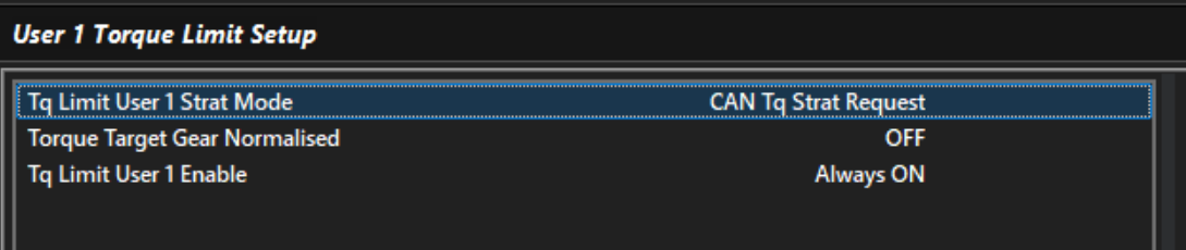
To use the incoming torque limit, you must setup a User Torque Limit. This allows the tuner to decide how they want the ECU to act on the incoming torque limit request.
To use the CAN Torque Limit Strat Select value, set the Strat Mode to CAN Tq Request, otherwise you can force a Strat of your choosing.
InfoIf the CAN Torque Limit Strat Select value is zero and The User Torque Limit Strat Mode is set to CAN Tq Strat Request, no limit will be applied.
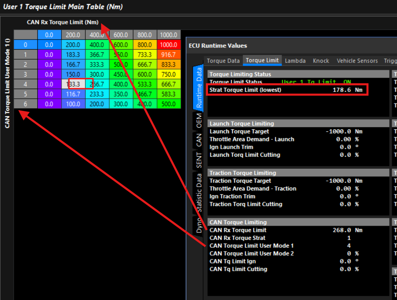
Setup the Torque Limit’s Main Table to utilize the CAN Rx Torque Limit value. You can also use the CAN Torque Limit User Modes like in the example below.
Here you can see the incoming request for is being modified for User Modes above 0:
EML-4 CAN Setup
EML-4 Setup.
Up the 3x EML-4 may be connected to the Emtron CAN bus. This allows the lambda data for up to 12 cylinders to be connected to the ECU. With the addition of every EML-4 module the CAN address for each data packet MUST use sequential addressing. The preferred addresses are listed below.
EML-4
CAN Data Address = 65
CAN Status Address = 66
EML-4
CAN Data Address = 67
CAN Status Address = 68
EML-4
CAN Data Address = 69
CAN Status Address = 70
ECU Setup.
ECU CAN Setup
Select an available CAN node, CAN1 or CAN 2
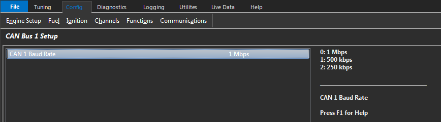
Select Baud Rate to 1Mbps
Turn the selected CAN channel ON
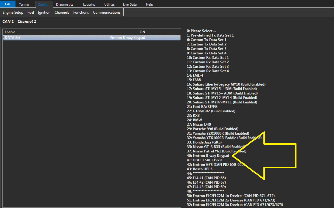
Select DATA Set = EML-4 (option 14)
Select CAN Address = 65 (On a single installation this address MUST match the EML-4 CAN Data address. With multiply EML-4 modules connected to the BUS use the lowest address. The ECU CAN protocol in the mode uses sequential addressing and expects the received CAN address to get larger.
NOTE: All other CAN settings are not used.
ECU Input Setup
The Software allows each EML-4 sensor channel to be assigned to a cylinder.
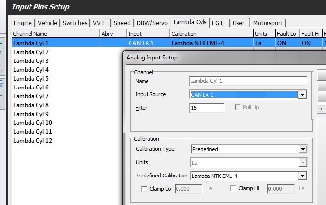
Select the correct CAN Lambda Channel .In this example Cylinder 1 has been allocated to the LA 1 channel on the first EML-4 module.
The 1st EML-4 assigns LA1-4, the 2nd EML-4 assigns LA 5-8, the 3rd EML-4 LA 9-12.
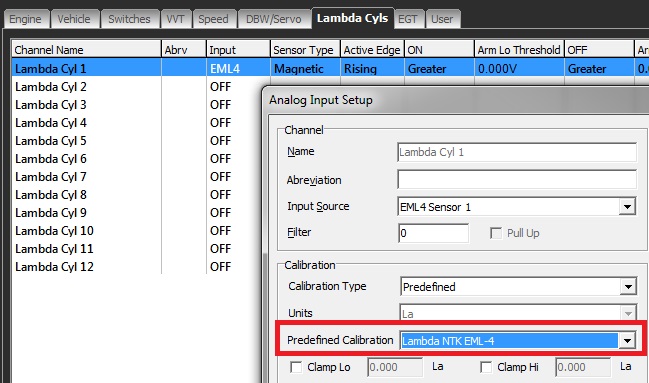
Select Predefined Calibration to Lambda NTK EML-4. Don’t select Custom. Select Clamp Lo and Clamp Hi if required.
The Fault Settings are not used from this form, as this operation if performed internally by the EML-4 are transferred to the ECU over CAN.
The Engine Limit Table is still used.
Emtron 8 Way Keypad
Configure Emtron CAN as follows to use Emtron 8 Way Keypad
Set CAN Baud Rate to 1Mbps
Config -> Communications -> CAN Bus 1/2 -> CAN Bus 1/2 Setup
Set CAN Channel Settings as follows :
Config -> Communications -> CAN Bus 1/2 - Channel 1-6 - 40 : Emtron 8 - way Keypad
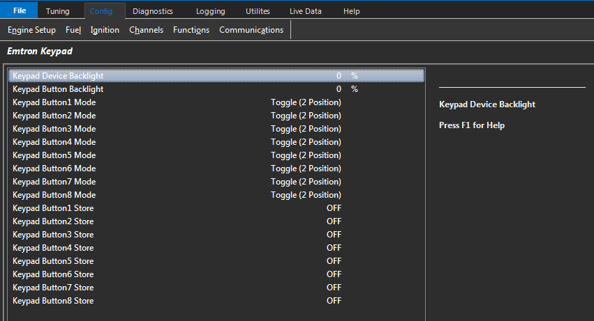
Configure the Keypad behavior as follows :
Config -> Communications -> Emtron CAN Devices -> Emtron Keypad
Keypad button behavior has multiple modes of configuration
0: Toggle (2 Position)
1: Sequential (3 Position)
2: Sequential (4 Position)
3: Binary (8 Position)
4: Momentary
Keypad Button1 Mode
Toggle: x2 Position
OFF - No LED
ON - Green LED
Sequential: x3 Positions
OFF - No LED
Position 1 - Green LED
Position 2 - Orange LED
Sequential: x4 Positions
OFF - No LED
Position 1 - Green LED
Position 2 - Orange LED
Position 3 - Red LED
Binary: x8 Positions
OFF - No LED
Position 1 - Green LED
Position 2 - Orange LED
Position 3 - Green & Orange LED
Position 4 - Red LED
Position 5 - Red & Green LED
Position 6 - Red & OrangeLED
Position 7 - Red & Green & Orange LED
Momentary: Green light ON while button is pressed
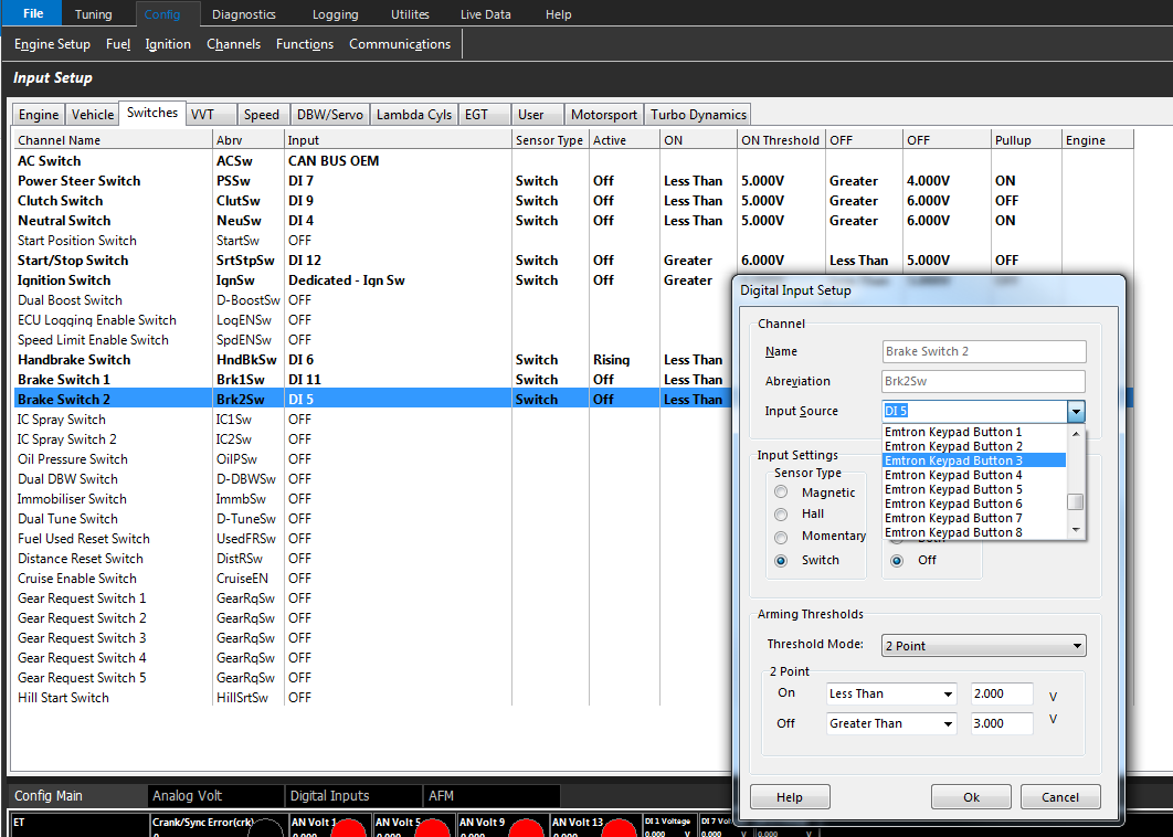
Assign Keypad inputs as follows :
Config -> Channels -> Input Setup ->
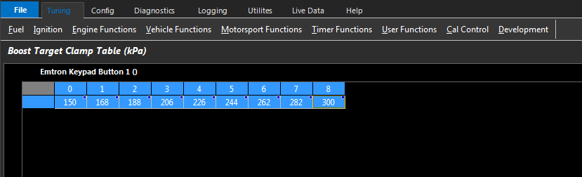
** When using Keypad input in multiple positions (sequential or binary), the keypad position runtime can be used in tables as in above example
Emtron EIC10 Setup
EIC10 ANV1-10 Tx Rate
0: 200 Hz (default)
1: 50 Hz
2: 100 Hz
3: 500 Hz
Controls the rate the Analog Channels 1 -10 are transmitted from the EIC10 device.
Applied to ALL connected EIC10 devices
EIC10 Frequency Tx Rate
0: 200 Hz (default)
1: 50 Hz
2: 100 Hz
3: 500 Hz
Controls the rate the Frequency data are transmitted from the EIC10 device.
Applied to ALL connected EIC10 devices
EIC10 #1 ANV7-10/Freq1-4 Pullup
0: OFF
1: ON
Enables 1k Pullup to 8.0V
EIC10 #1 Frequency 1-4 Edge
0: OFF
1: Falling
2: Rising
EIC10 #2 ANV7-10/Freq1-4 Pullup
0: OFF
1: ON
Enables 1k Pullup to 8.0V
EIC10 #2 Frequency 1-4 Edge
0: OFF
1: Falling
2: Rising
Emtron EIC16M Setup
EIC16M #1 ANV1-12 Tx Rate
0: 200 Hz (default)
1: 50 Hz
2: 100 Hz
3: 500 Hz
Controls the rate the Analog Channels 1 -12 are transmitted from the EIC16 device.
Applied to ALL connected EIC16 devices
EIC16M #1 ANV13-16 Tx Rate
0: 200 Hz (default)
1: 50 Hz
2: 100 Hz
3: 500 Hz
Controls the rate the Analog Channels 13 -16 are transmitted from the EIC16 device.
Applied to ALL connected EIC16 devices
EIC16M #1 Frequency Tx Rate
0: 200 Hz (default)
1: 50 Hz
2: 100 Hz
3: 500 Hz
Controls the rate the Frequency data are transmitted from the EIC16 device.
Applied to ALL connected EIC16 devices
EIC16M #1 ANV9-12 Pullup
0: OFF
1: ON
Enables 1k Pullup to 5.0V
EIC16M #1 Freq 1-4 Pullup
0: OFF
1: ON
Enables 1k Pullup to 8.0V
EIC16M #1 Frequency 1-4 Edge
0: OFF
1: Falling
2: Rising
Emtron ETC4 Setup
ETC4 CAN Data Tx Rate
0: 200 Hz (default)
1: 50 Hz
2: 100 Hz
3: 500 Hz
Controls the rate the EGT Channels are transmitted from the ETC device.
Applied to ALL connected ETC devices
ETC4 Fault Value
Controls the EGT value when the Input is in Fault or Open Circuit
Applied to ALL connected ETC devices
Emtron ETC8M Setup
ETC8M CAN Data Tx Rate
0: 200 Hz (default)
1: 50 Hz
2: 100 Hz
3: 500 Hz
Controls the rate the EGT Channels are transmitted from the ETC device.
Applied to ALL connected ETC devices
ETC8M Fault Value
Controls the EGT value when the Input is in Fault or Open Circuit
Applied to ALL connected ETC devices
Emtron Lambda to CAN (ELC/ELCM) Setup
For details :
Emtron Lambda CAN Manual
Click the link below to download or visit Emtron www Downloads
ELC
Reset CAN IDs to Default
0: OFF
1: ON
This will reset the ELC CAN IDs back to their default values
Channel 1 = 671, Channel 2 = 672
Set back to zero when finished.
Enable Heater Override
0: OFF
1: ON
When enabled, the ECU controls when the Lambda heater is ON or OFF. This is done through the “ELC HEater RPM Lockout” and “ELC Heater Post Start Lockout: settings.
When disable the ELC controls the heater(s) which will turn On 15 secs after the device power up.
Enable EMAP
0: OFF
1: ON
When enabled, the ECU will send EMAP data to the ELC. This units should be in kPa
** When enabled please make sure the EMAP is configured correctly inside the ECU.
ELC Heater RPM Lockout
RPM Below which heater will be locked out
ELC Heater Post Start Lockout
Timer before which heater will turned on Post Start up
ELC Lambda 1 Test Enable
Forces the ELC to send this Test Value over the CAN bus.
Allows the user to confirm the ECU calibration is setup correctly.
0 = OFF
ELC Lambda 2 Test Enable
Forces the ELC to send this Test Value over the CAN bus.
Allows the user to confirm the ECU calibration is setup correctly.
0 = OFF
Generic Dash Configuration
Configure Emtron CAN as follows to send Pre-Defined Data set for most Dash Systems
*** Emtron has provided Pre-Defined Data set to most dash manufacturers to match these settings
Set CAN Baud Rate to 1Mbps
Config -> Communications -> CAN Bus 1/2 -> CAN Bus 1/2 Setup
Set a CAN Channel Setting as follows :
Config -> Communications -> CAN Bus 1/2 - Channel 1-6
Parameter Scaling
ALL data/parameters transmitted from the ECU over CAN have units defined by the corresponding parameter calibration table(s). This can be setup and adjusted through the PC tuning software Emtune.
All Data is unsigned
All Data is 16 bits
Low byte of each word (16bit) is transmitted first.
Examples:
Temperature in degrees Celsius or Fahrenheit
Pressure in kPa, PSI, InHg
Speed in Kph, mph, m/s
Speed in Kph, mph, m/s
Type
Units
Min Value
Max Value
Conversion Raw to Displayed Value
Position
%Posn
-100.0 %
100.0 %
Display = ECU value x 0.1 - 100 OR ECU value A: 0000 becomes -100.0 % ECU value B: 2000 becomes 100.0 %
Pressure
kPa/PSI
0.0
6500.0
Display = ECU value x 0.1 OR ECU value A: 0 becomes 0.0 kPa/PSI ECU value B: 1000 becomes 100.0 kPa/PSI
Temperature
oC / oF
-50.0
250.0
Display = ECU value x 0.1 - 50 OR ECU value A: 0 becomes -50.0 oC/ oF ECU value B: 1500 becomes 100.0 oC / oF
Lambda
La
0.000
2.000
Display = ECU value x 0.001 OR ECU value A 0 becomes 0.000 La ECU value B 1000 becomes 1.000 La
Type
Units
Min Value
Max Value
Conversion Raw to Displayed Value
Speed
Kph/mph
0.0
6500.0
Display = ECU value x 0.1 OR ECU value A 0 becomes 0.0 kph ECU value B 1000 becomes 100.0 kph
Ignition Angle
oBTDC
-100.0 oBTDC
100.0 oBTDC
Display = ECU value x 0.1 - 100 OR ECU value A 1000 becomes 0.0 oBTDC ECU value B 2000 becomes 100.0 oBTDC
Voltage
V
0.000
20.000
Display = ECU value x 0.001 OR ECU value A 0 becomes 0.000V ECU value B 20000 becomes 20.000V
Percentage1
%
0.0
100.0
Display = ECU value x 0.1 OR ECU value A 0 becomes 0.0% ECU value B 1000 becomes 100.0%
Percentage2
%
-100.00
100.00
Display = ECU value x 0.01 - 100 OR ECU value A 0 becomes -100.00% ECU value B 10000 becomes 0.00% ECU value C 20000 becomes +100.00%
Type
Units
Min Value
Max Value
Conversion Raw to Displayed Value
Rate of Change1
%/sec
-100.0
+ 100.0
Display = ECU value x 0.1 - 100 OR ECU value A 0 becomes -100.0 %/sec ECU value B 1000 becomes 0.0 %/sec Or ECU value B 2000 becomes +100.0 %/sec
Rate of Change2
rpm/sec
-20000
20000
Display = ECU value x - 20000 OR ECU value A 0 becomes - 20000 rpm/sec ECU value B 20000 becomes 0 rpm /sec Or ECU value B 40000 becomes + 20000 %/sec
G-Force
G
-10.00 G
10.00 G
Display = ECU value x 0.01 - 10 OR ECU value A 0 becomes -10.00 G ECU value B 1000 becomes 0.00 G or ECU value B 2000 becomes 10.00 G
RPM
RPM
0
300000
Display = ECU value x 1 OR ECU value A 0 becomes 0 RPM ECU value B 20000 becomes 20000 RPM
Pressure Diff
kPa/PSI
0.0
6500.0
Display = ECU value x 0.1 - 1000 OR ECU value A: 10000 becomes 0.0 kPa/PSI ECU value B: 8000 becomes - 200.0 kPa/PSI
Counter
0
65535
Display = ECU value OR ECU value A 0 becomes 0 ECU value B 10 becomes 10
VVT Position
Deg
-100.0
+100.0
Display = ECU value x 0.1 - 200 OR ECU value A: 2000 becomes 0.0 Deg ECU value B: 2304 becomes 30.4 Deg (Cam Advanced) ECU value 3: 1871 becomes -12.9. Deg (Cam Retarded)
Pre-defined Rx Set 1
Pre-defined Rx Set 1
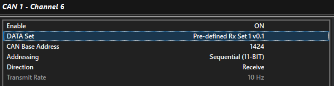
This data set allows a huge range of parameters to be read from the CAN bus and used by the ECU.
The data is received sequentially from ID 1424 to 1433.
Message 5 (ID 1428) includes the Emtron CAN Torque Limit Rx frame. It is received as part of this data set with the lowest priority.
Raw data received is displayed in the F3 window on the CAN Tab.
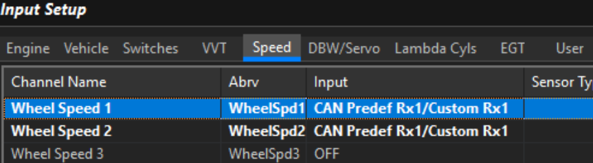
To use the data you must set the relevant input channel’s source to “CAN Predef Rx 1/Custom Rx1”.
Example: Wheel Speed Channels:
Example: Gear Detection:
Pre-defined Transmit Set 1
All 16 bit values have low byte transmitted first by the ECU. Sequential addressing is used. All parameters are transferred in the units defined inside the ECU. These can be rescaled if required by the receiving device.
Custom Packet 1 contains 10 Message Objects each with a different sequential address. This can be selected on CAN1 or CAN2 and on any of the 6 channels within that CAN node. In total the Custom Packet 1 transmits 40 parameters on one CAN Channel.
NOTE: If all 6 channels were used within one CAN node a total of 240 parameter could be transmitted
Message 1
Address: 1250 (Emtron preferred. User Adjustable)
Transmits: 8 bytes/4 parameters.
Addressing Mode: Sequential.
CAN Address
Byte Position
Parameter
Unit
1250
1-2
Engine Speed
rpm
1250
3-4
Engine Manifold Pressure
Pressure
1250
5-6
Engine Temperature
Temperature
1250
7-8
Engine Inlet Temp
Temperature
Message 2
Address: 1251 (Sequential based on address in Message 1)
Transmits: 8 bytes/4 parameters.
Addressing Mode: Sequential.
CAN Address
Byte Position
Parameter
Unit
1251
1-2
Throttle Position 1
Position
1251
3-4
Estimated Charge Temp
Temperature
1251
5-6
Gear
NA
1251
7-8
Battery Volts
Voltage
Message 3
Address: 1252 (Sequential based on address in Message 2)
Transmits: 8 bytes/4 parameters.
Addressing Mode: Sequential.
CAN Address
Byte Position
Parameter
Unit
1252
1-2
Oil Pressure
Pressure
1252
3-4
Oil Temperature
Temperature
1252
5-6
Fuel Pressure
Pressure
1252
7-8
Fuel Temperature
Temperature
Message 4
Address: 1253 (Sequential based on address in Message 3)
Transmits: 8 bytes/4 parameters.
Addressing Mode: Sequential.
CAN Address
Byte Position
Parameter
Unit
1253
1-2
Exhaust Pressure
Pressure
1253
3-4
Fuel Pressure Differential
Pressure Diff
1253
5-6
Crankcase Pressure
Pressure
1253
7-8
Coolant Pressure
Pressure
Message 5
Address: 1254 (Sequential based on address in Message 4)
Transmits: 8 bytes/4 parameters.
Addressing Mode: Sequential.
CAN Address
Byte Position
Parameter
Unit
1254
1-2
Lambda 1
La
1254
3-4
Lambda 1
La
1254
5-6
Lambda Target
La
1254
7-8
Drive Speed
Speed
Message 6
Address: 1255 (Sequential based on address in Message 5)
Transmits: 8 bytes/4 parameters.
Addressing Mode: Sequential.
CAN Address
Byte Position
Parameter
Unit
1255
1-2
Lambda 1 Short
Percentage2
1255
3-4
Lambda 2 Short
Percentage2
1255
5-6
Lambda 2 Long
Percentage2
1255
7-8
Lambda 2 Long
Percentage2
Message 7
Address: 1256 (Sequential based on address in Message 6)
Transmits: 8 bytes/4 parameters.
Addressing Mode: Sequential.
CAN Address
Byte Position
Parameter
Unit
1256
1-2
Injector Duty Cycle
Percentage1
1256
3-4
Ignition Angle
Ign Angle
1256
5-6
Baro
Pressure
1256
7-8
ECU Temp
Temperature
Message 8
Address: 1257 (Sequential based on address in Message 7)
Transmits: 8 bytes/4 parameters.
Addressing Mode: Sequential.
CAN Address
Byte Position
Parameter
Unit
1257
1-2
dTPS
Rate of Change1
1257
3-4
dRPM
Rate of Change2
1257
5-6
Fuel Cut Level
Percentage1
1257
7-8
Ignition Cut Level
Percentage1
Message 9
Address: 1258 (Sequential based on address in Message 8)
Transmits: 8 bytes/4 parameters.
Addressing Mode: Sequential.
CAN Address
Byte Position
Parameter
Unit
1258
1-2
Ethanol Content
Percentage1
1258
3-4
G-Force Lat
G-Force
1258
5-6
G-Force Long
G-Force
1258
7-8
G-Force Vert
G-Force
Message 10
Address: 1259 (Sequential based on address in Message 9)
Transmits: 8 bytes/4 parameters.
Addressing Mode: Sequential.
CAN Address
Byte Position
Parameter
Unit
1259
1-2
Crank/Cam Error Counter
counter
1259
3-4
Max Engine Speed
rpm
1259
5-6
Sync Position
Percentage1
1259
7-8
DTC Count
counter
Racepak Dash CAN Setup
This section describes how to connect an Racepak IQ3 dash to the Emtron CAN bus.
Racepak Device Compatibility
250-ds-Iq3s - Street display
250-ds-iq3d - Drag logger
250-ds-iq3ld - Logger dash
250-ds-iq3sl - Street logger
250-ds-iq3 – Display only
These devices require an interfacing module to talk to additional ECU systems/components
** Requires Universal EFI Module 230-vm-efiucan
Racepak CAN Wiring colors
Green = ground
Black = CAN Lo
White = CAN Hi
ECU Setup
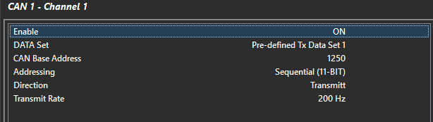
Select either CAN1 or CAN2
Select a Channel with CAN1 or CAN2
Set Enable to ON
Set CAN Address = 1250
Select required DATA Set; Predefined or custom
Set Direction to transmit
Set Addressing to sequential
Set required Transmit Rate. CAUTION. Do NOT set to high as this will limit the available bandwidth to other devices on the bus
Racepak Setup
A default RacePak Config file has be created to match the Emtron ECU Predefined1 DATA set. This is called Emtron_Predefined1_IQ3_Config.rcg. This should be programmed into the ECU.
Sequential Addressing
Many CAN data sets in the ECU use a sequential addressing approach. This simply means that each message is on an ID that is some offset from the “Base Address”.
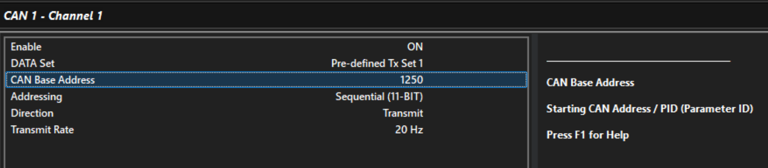
In the above example, Pre-defined Tx Set 1 send it’s first frame on ID 1250. The whole data set contains 10 frames. They’re sent out incrementally from 1250.
eg: 1250, 1251, 1252, 1253 … 1259.
Custom Rx Data Sets
All parameters are received as 16 bit unsigned integers.
A CAN frame holds up to 8 bytes of data which means each frame can hold up to 4 parameters.
Each parameter must occupy 2 bytes.
When the receiving CAN Channel is set to Sequential, the ID must be increased by 1 every 4 channels so
that the whole data set can be processed.
Example:
Custom Rx Data 1 set contains 5 or more parameters.
CAN Channel 1 is set to Receive Custom Tx Data Set 1, Sequentially, on ID 1000.