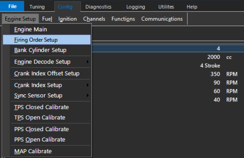
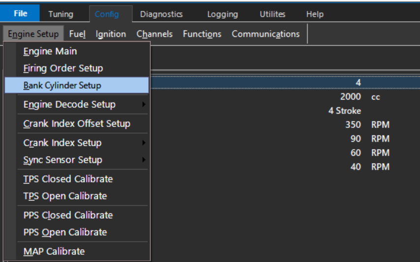
Engine Setup

Emtune has a very systematical approach to configuration.

Start on the left side “Engine Setup”, and work your way over from left to right.

Do not skip sections. Following this practice as accurately as possible will ensure tuning process will move smoothly in the future.

Improper entry in any part of the setup could be detrimental to the electronics AND the hardware!
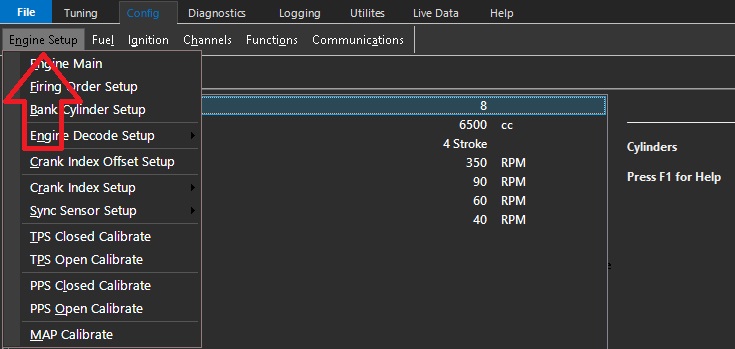
Image Image

Setup each tab from top to bottom. See help file for explanation of each individual function, as well as help text in the respective configuration screens.

**Crank index offset MUST always be checked regardless of trigger pre-configuration.
Copyright © 2026 Emtron Australia Pty Ltd

Subsections of Engine Setup

Engine Main

Image Image

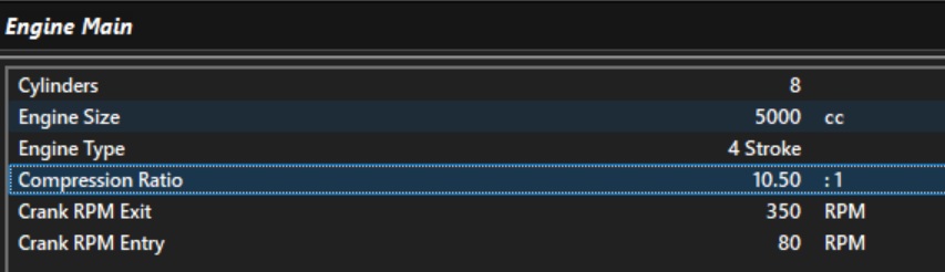
Engine Type

This setting defines the two engine cycle type supported by the ECU.

4-Stroke – The most common engine type. One complete engine cycle occurs over two crankshaft revolutions (720°).

2-Stroke – One complete engine cycle occurs over one crankshaft revolution (360°).

Rotary engines are regarded as 2 stroke engines

Image Image

Engine Size

The total engine displacement, entered in cc.

This setting is critical and must be configured accurately, as the engine displacement is used by the ECU in various calculations to build the engine model.

Image Image

Compression Ratio

This value is the static compression ratio of the engine. ie: Swept volume over clearance volume.

NOTE: This input effects the Torque Model as well as the Fuel Model: Expansion Ratio calculation.

Crank RPM Entry

Used to determine the Engine Speed which is considered as cranking. Various compensations also use this value to determine when to be enabled.

The value entered must be low enough at cranking speeds to ensure the cranking compensations can be enabled.

Crank RPM Exit

Defines the engine speed above which the engine is considered to be running. Various compensations also use this value to determine when they should be enabled.

NOTE: Should you have an engine that is difficult to initially cold start, that is it doesn’t start on first crank, rather on the second or third attempt, then increasing the Crank RPM Exit in some instances can help. This allows the engine to utilize the Crank Comp Table for a little longer allowing for a faster start and quicker handover to a run condition.

Engine Speed Valid

Engine Speed is considered valid when it exceeds this value, allowing the ECU to begin Fuel and Ignition control.

Engine Speed Invalid

Engine Speed is considered invalid when it falls below this value, causing the ECU to stop Fuel and Ignition control.


Tuning Tip. Any increase in the accuracy of the information entered into the ECU configuration will help reduce calibration error.

The importance of entering the correct engine information cannot be overstated if the project is to be torque modelled. Extra time should be spent to ensure that all configuration entries are accurate.

For example, if an engine is described as a 6.2-litre engine but its actual capacity is 6162 cc, the correct value of 6162 cc should be entered. Any errors introduced during the configuration stage will carry through into the tuning process and contribute to calibration error.

This applies to all configuration entries, not just engine capacity. In short, the more effort you put into getting the configuration correct, the easier and more accurate the tuning process will be.


Copyright © 2026 Emtron Australia Pty Ltd

Firing Order Setup

Firing Order Setup

This table is used to define the engine firing order and the base angle for each cylinder.

Most engines are even-fire, meaning that each firing event occurs at an equal crankshaft angle from the previous firing event.

Image Image

For example, a 4-cylinder, 4-stroke, even-fire engine commonly uses a firing order of 1-3-4-2.

The corresponding base angles are: 0° – 180° – 360° – 540°

For even-fire engines, the Generate Base Angles function can be used to automatically calculate the base angles once the firing order is entered.

Image Image

For odd-fire engines, the base angles are not equally spaced and must be entered manually, as shown below for a Dodge Viper application.

Image Image

Copyright © 2026 Emtron Australia Pty Ltd

Bank Cylinder Setup

Bank Cylinder Setup

Assigns each cylinder to Bank 1 or Bank 2. This allows the ECU to determine which cylinders the bank-specific fuel or ignition trims are applied to.

Image Image

Used in the Bank controlled Fuel Models 5-7.

Image Image