In both Speed Density and MAF modes the ECU performs the following steps to calculate the final Injector OpeningTime.
Calculate the Air Mass per cylinder.
In Speed Density Mode PV = nRT is used to Calculate Air Mass.
In MAF mode, Air Mass is measured directly from the MAF Sensor.
In Throttle Mass Flow (TMF) mode the Air Mass is calculated by looking at the pressure ratio across the throttle body, calculating the
throttle area and applying these to a 2nd order thermodynamics equation.
Calculate Fuel Mass using Air Mass, Stoichiometric ratio, Lambda Target, Engine VE and other parameters outlined below.
Calculate Effective Pulse Width using Fuel Mass, Injector Mass Flow, Fuel Density and Bernoulli’s equation for Fuel Pressure correction.
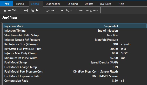
Fuel Model: Charge Temp
This setting ONLY applies when the Fuel Model is selected to Speed Density. There are 2 separate methods that control how the fueling is adjusted based on Charge Temperature.
With this setting set to ON (and this is the recommended setting) the Charge Temp will be used to adjust the Air Mass as part of the Ideal Gas Law equation. The ECU is then able to automatically adjust the Air Mass (g) based on this temperature.
When this setting is OFF the Air Mass is not modified base on Charge Temp. Instead the Tuning View -> Compensations -> Charge Temp Comp Table 1 can be used to manually correct the fueling based on Charge Temperature.
NOTE: It is NOT recommended to have both systems ON at the same time.
Fuel Model: Fuel Pressure
This setting applies to ALL Fuel Models. A Fuel Pressure Sensor MUST be fitted. The ECU will correct/adjust the Injector Flow as the differential pressure across the injector changes. This means any fuel surge causing an sudden drop in fuel pressure the ECU can correct the fueling and maintain the correct mixture.
NOTE: Fuel Pressure Units MUST be in kPa to match both the MAP and BAP units.
Sensor Requirements
Additional to MAP and MAF the following sensors should be used to take full advantage of ECUs Fuel Model(s):
Fuel Temperature.
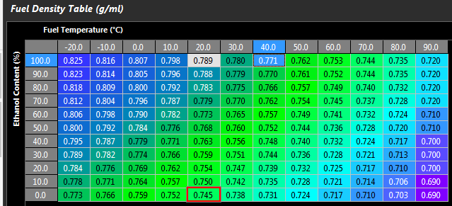
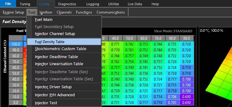
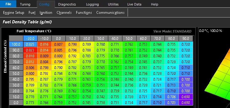
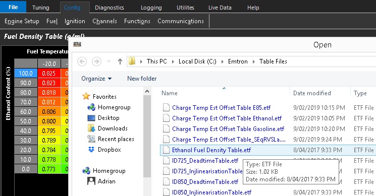
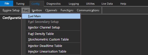
Used to help accurately calculate Fuel Density (g/ml) by spanning the x-axis on the Fuel Density Table (see Config View -> Fuel -> Fuel Density Table). See Figure 1 below.
If the Fuel Temp channel is not selected it defaults to 20 DegC which will then be used to span the Fuel Density Table. Note: If an Ethanol Sensor is selected the Fuel Temp information from the sensor is automatically copied into the Fuel Temp Runtime.
Figure 1: Fuel Density Table
Fuel Pressure Sensor.
Required if Fuel Pressure Correction is to be used.
Ethanol Sensor
Strongly recommended to use this sensor when running Ethanol based fuels. It allows the ECU to automatically correct fueling based on Ethanol Content. i.e Petrol (0% Ethanol) up to 100% Ethanol. It does this by adjusting the Fuel Density and Stoichiometric Ratio . See Figure 1.
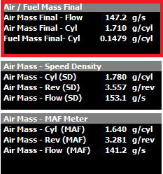
The Final Air and Fuel Mass used by the ECU can be viewed from the Runtime menu -> Fuel Tab (F3). You can also view data from the Speed Density (SD) and MAF Sensor Calculations. See Figure 2.
Figure 2. Final Mass values (Fuel and Air) shown in red box.
Fuel Model Modes
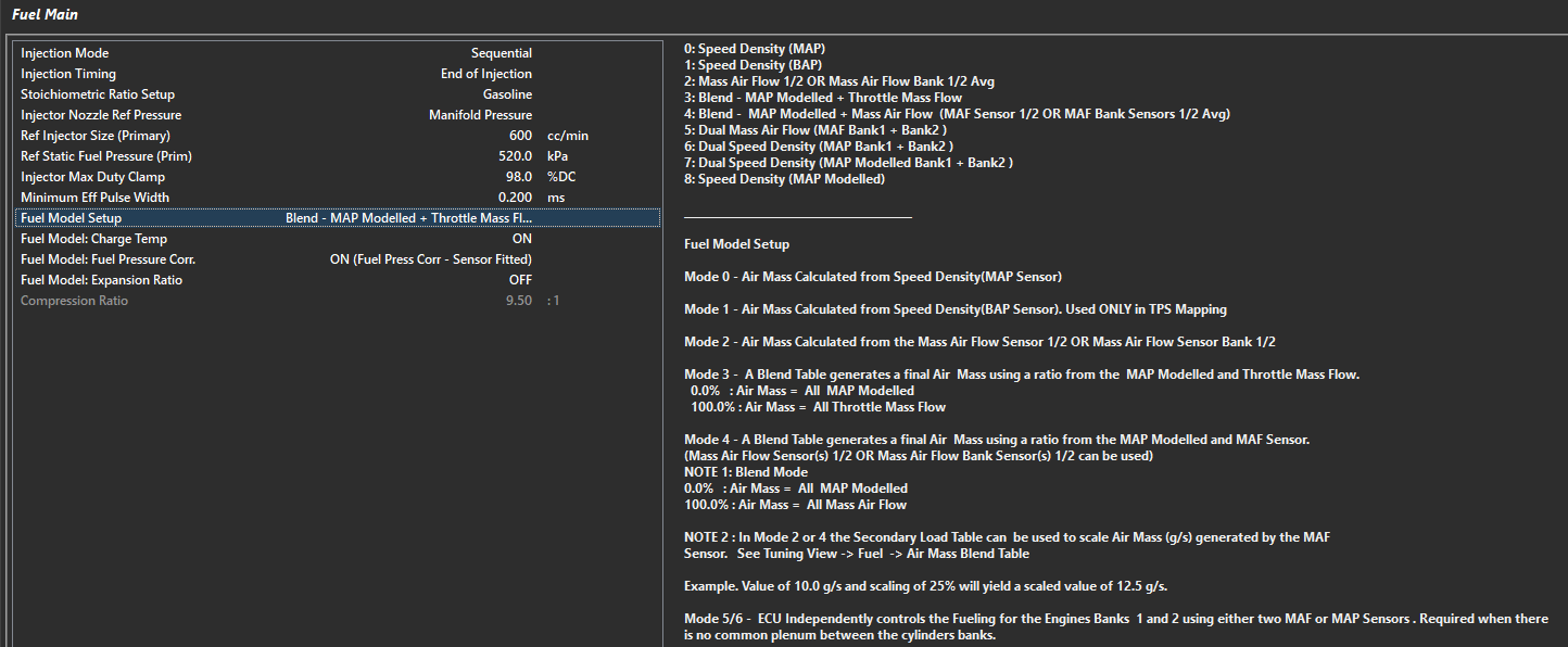
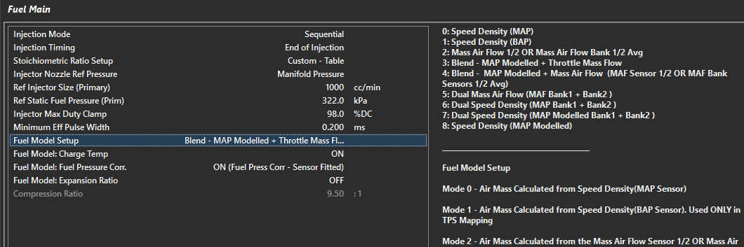
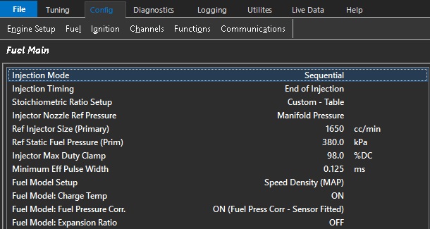
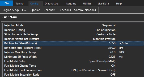
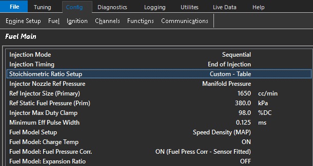
To configure the Fuel Model select the appropriate method from the Config View -> Fuel -> Fuel Main -> Fuel Model Setup
Air and Fuel Mass Modifier Tables
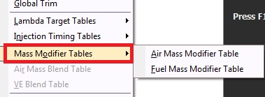
There are additional Tables available to modify the Air Mass and Fuel Mass if required. These can be switching ON from Tuning View -> Fuel Table Control -> Mass Modifier Tables. See Figure 3.
Figure 3: Mass Modifier Tables
Fuel Model: Fuel Pressure
Fuel Model : Fuel Pressure
Fuel Model: Fuel Pressure Corr.
Fuel Pressure Correction - Primary Injectors
** Secondary Injectors configured separately
Includes the Fuel Pressure in the Fuel Model Calculation. The ECU is able to automatically adjust the Mass Injector Flow based on the differential pressure across the Injector.
** NOTE: ONLY uses Fuel Pressure 1 Input Channel **
0: OFF
1: ON (Fuel Press Corr - Sensor Fitted)
2: ON (Static Fuel Pressure - No Sensor)
0 = ECU will not correct fuel mass at all. This means the Fuel Mass Calculation is functioning solely off the Ref Injector Size (Primary) and Ref Static Fuel Pressure (Prim).
** Using a Vacuum Referenced (rising/falling rate regulator) should provide stable differential pressure.
1 = ECU will calculate new fuel mass requirements based on deviation from Ref Static Fuel Pressure (Prim) value.
2 = ECU will calculate differential pressure loss (without a sensor) assuming the Ref Static Fuel Pressure (Prim) cannot be maintained due to having a non-vacuum referenced/rising rate fuel pressure regulation system installed (static pressure all the time).
Channels to reference :
Fuel Pressure 1 - Pressure value generated by calculated channel - as calibrated by input setup
Fuel Pressure 1 Diff - Effective/Relative/Differential pressure across injector - uses Injector Nozzel Ref Pressure to calculate
Fuel Model - Fuel Pressure Correction (Prim) % - Percentage of Fuel Mass correction applied due to Fuel Pressure 1 Diff Offset
**** Recommended Setting - “1” due to Vacuum Referenced regulators not always providing 1:1 pressure change vs Injector Nozzle Ref Pressure and other inadequacies of most fuel systems (starvation, voltage supply, out-flowing, etc)**
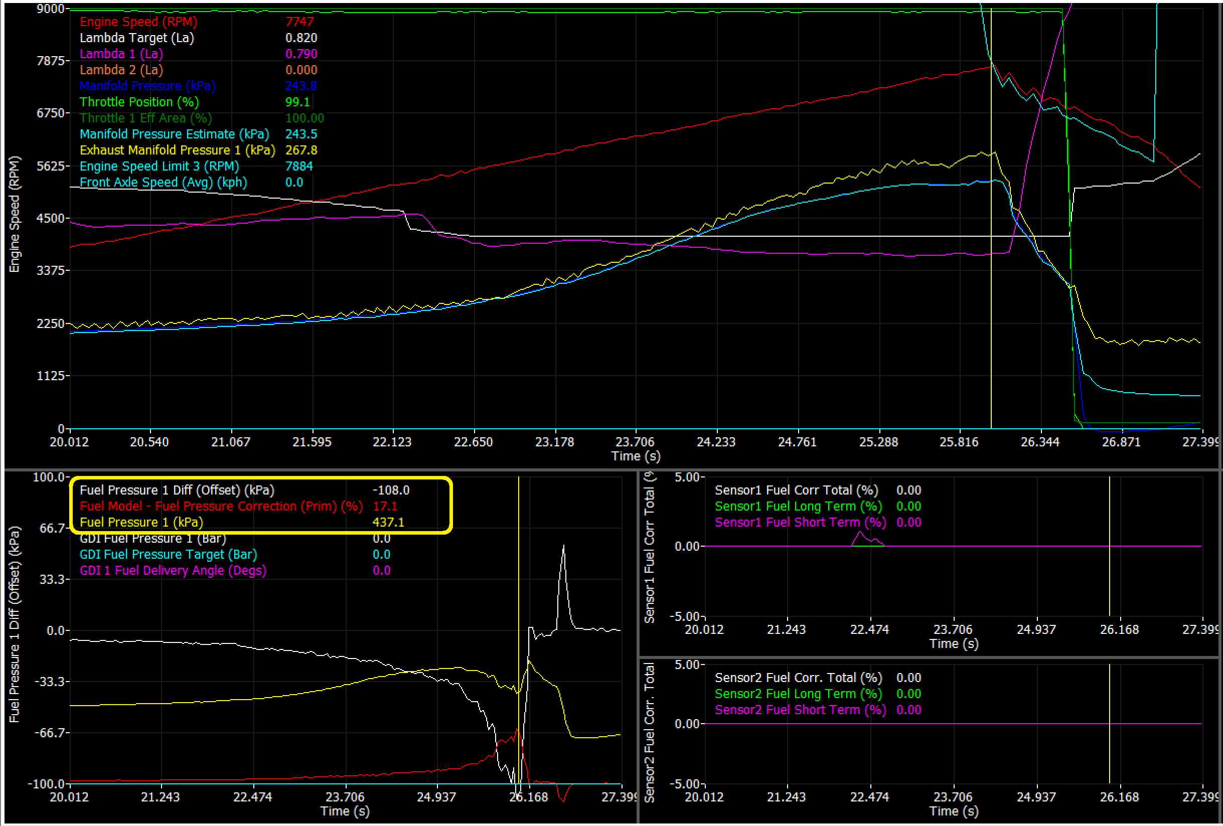
Example demonstrating loss of fuel pressure and ECU compensating fuel mass until specified “cut off - Fuel Pressure Engine Protection
** Observe Lambda staying on target with negative Fuel 1 Diff Offset, and Positive Fuel Model - Fuel Pressure Correction (Prim)
Fuel Density Table
Fuel Density Table
The Fuel Density Table is utilized by the Fuel Model to determine the fuel mass.
Fuel Temperature has a major influence on the fuel density and hence the mass of the fuel.
This 3D table can also account for fuel density changes based on any parameter in the ECU.
This setting is particularly useful when using multiple fuel compositions such as ethanol which also influence the fuel mass.
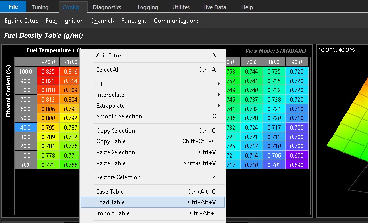
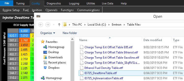
The Emtune software has pre determined Fuel Density Tables available in it that are only a right click of the mouse away
By selecting “Load Table” you can quickly arrive at the correct density table to suit commonly used fuels.
The Ethanol Fuel Density Table.etf is as shown in the example above & spans the increase in ethanol against gasoline.
Methanol & Gasoline specific Fuel density tables are also included.
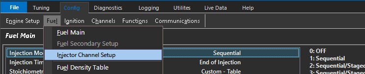
Fuel Main
Fuel Model Blending control
Fuel Model Blending Control
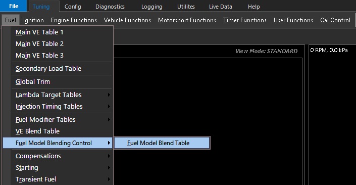
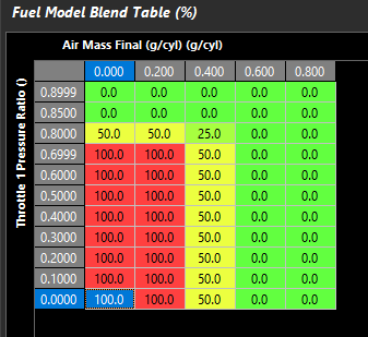
The Fuel Model Blending Control Table is available when “Blend” modes are being used.
Common uses for Fuel Model Blending would be when switching between MAF and Speed Density (when MAF resolution may become ineffective for the application), or Throttle Mass Flow and Speed Density (when Throttle Pressure Ratio doesn’t support TMF measurement).
** Note the Blend Function actually connects to MAP Modeling which allows for further blending of fuel model modes additionally. See - MAP Modeling
Select “blending” - Modes 3 or 4 in :
Config -> Fuel -> Fuel Model Setup
This table is available for the user to control the ratio of which model is used.
MODE 3:
0.0% : Air Mass = All MAP Modelled
100.0% : Air Mass = All Throttle Mass Flow
MODE 4:
0.0% : Air Mass = All MAP Modelled
100.0% : Air Mass = All Mass Air Flow Sensor
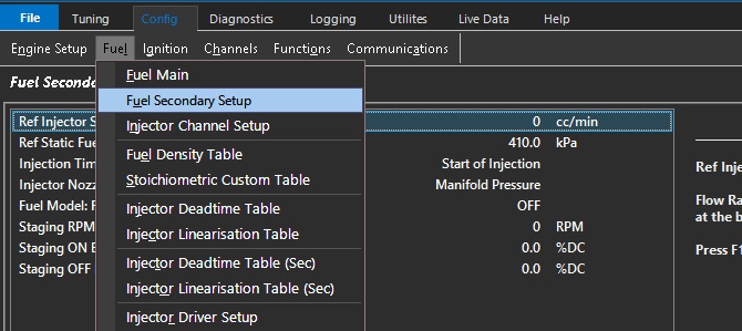
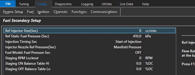
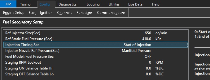
Fuel Secondary Setup
Fuel Secondary Setup
Fuel Table Control
Fuel Table Control
Tuning -> Fuel -> Fuel Table Control
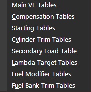
The fuel table control allows you to tailor the number of fuel tables used and how they are utilized.
There are 3 Main VE tables available, they can be used individually, on a user selectable cal slot
(Example: The position of the Si Drive selector in a Subaru Sti over the CAN BUS)
On a user defined Z-Axis (Example: Spanned across ethanol content)
Or a user defined blend across tables based on specified parameters.
This allows a user defined level of complexity
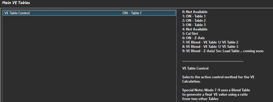
Main VE Fuel Table Control Tab shown as an example.
This level of complexity flexibility is common to all fuel control tables.
Compensation Tables:
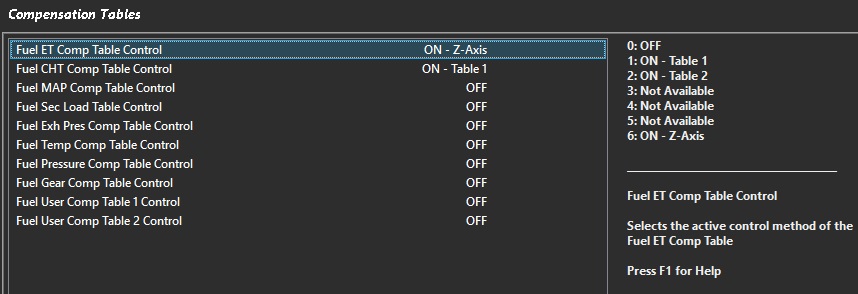
The compensation tables offer the tuner the ability to compensate for a wide range of variable conditions
All compensation tables are user definable 3D tables that can be utilized against any runtime
More commonly used compensations are already named & linked to their specific purpose
With 2 additional User Comp tables where all parameters are defined by the user.
Sequential Primary Injectors: Allocated on Injection Channels 1-8.
Sequential Secondary Injectors: Allocated on Injection Channels 9-16.
**** Staging mode must have primary cylinders start with Cylinder 1**
Injection Mode = Non Sequential
In this mode the odd injector channels are fired on one cycle, and even injector channels on the next. The ECU will calculate fuel mass required and divide it by the number of cylinders NOT the number of injector channels.
**** Cylinder numbering, bank assignment, firing order is disregarded in this injection mode**
Example 1:
6 injectors connected individually on a 6 cylinder engine
ECU will activate 1+3+5 on one TDC, 2+4+6 on the next (odd and even)
Example 2:
6 injectors connected individually on a 6 cylinder engine but ordered so the cylinders fire per bank
If the engine has dual banks (123 / 456), and the firing order is 1536242, the installer can re-order the cylinders vs injector outputs to synchronize firing per bank
ECU will activate 1+3+5 on one TDC, 2+4+6 on the next (odd and even)
Injection Channels 123456
Cylinder Numbers 142536
This will fire 1+2+3 cylinders on one cycle, 4+5+6 on the next
8 injectors connected individually on a 8 cylinder engine but ordered so the cylinders fire per bank
If the engine has dual banks (1357 / 2468), and the firing order is 18436572, the installer can re-order the cylinders vs injector outputs to synchronize firing per bank
ECU will activate 1+3+5+7 on one TDC, 2+4+6+8 on the next (odd and even)
Injection Channels 12345678
Cylinder Numbers 12345678
If the engine has dual banks (1234 / 5678), and the firing order is 15486372, the installer can re-order the cylinders vs injector outputs to synchronize firing per bank
ECU will activate 1+3+5+7 on one TDC, 2+4+6+8 on the next (odd and even)
Injection Channels 12345678
Cylinder Numbers 15263748
ECU will activate 1+2+3+4 on one TDC, 5+6+7+8 on the next (odd and even)
Example 3:
2 injectors connected with 3 injectors paired to each output on a 6 cylinder engine
Engine will fire output 1 on one TDC, 2 on the next
The installer can group the cylinders they want to fire on each cycle
** This method will NOT provide the best injector deadtime and linearization control.
Injection Mode = Sequential/Staged Group
WARNING:
DO NOT use Fuel Engine Limiting when Staged Injection is enabled.
If there is an Injection Phasing difference between Primary and Secondary Injectors,
Cut synchronization is not always possible and may result in engine damage.
Ignition Liming is recommended.
In this mode the Primary Injectors are sequential and the Secondary Injectors are Group/Non sequential. The Secondary Injectors are opened once per engine cycle. The Secondary Odd and Even Injection channels are run anti-phase. The Injectors on Even Channels are started at 0.0 Degrees BTDC. The Injectors on Odd Channels are started at 360.0 Degrees BTDC
Cylinder (Prim) = Enter the cylinder number for each Injection Channel connected to a primary injector
Inj Count (Sec) = Enter the number of secondary injectors connected to an Injection Channel. This is group staged and is NOT referenced to cylinders.
Example 3:
Sequential Primary Injectors: Allocated on Injection Channels 1-4.
Grouped Secondary Injectors: One injector on each Injection Channel 5,6,7,8
Example 4:
Sequential Primary Injectors: Allocated on Injection Channels 1-8.
Grouped Secondary Injectors: Two injectors on each Injection Channel 9,10.
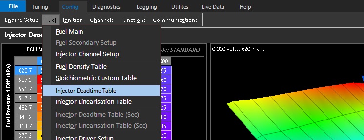
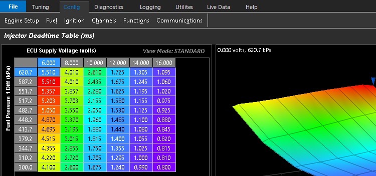
Injector Deadtime Table
Injector Dead Time Table
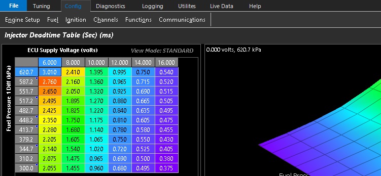
The Injector Dead Time Table is utilized by the ECU to compensate for the latency (or Deadtime) of the Primary injectors
The injector deadtime is the time factor in milliseconds when no fuel is injected accounting for the reaction time of the injector.
Setting the correct deadtime of an injector is critical for ECU fuel mass calculations.
All injectors have a deadtime which may be affected by a number of factors.
The voltage at the injector generally has the highest influence on the injector deadtime.
Other factors such as fuel pressure also have a major affect on the injector deadtime.
Saturated injectors tend to have longer deadtimes when compared to peak & hold injectors
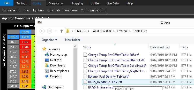
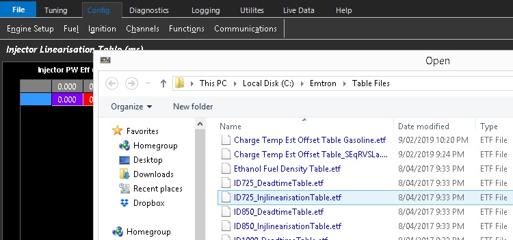
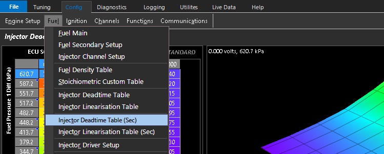
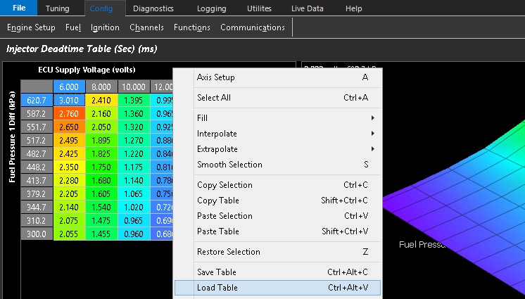
The Emtune software has commonly used Injector Deadtime Tables available in it that are only a right click of the mouse away.
Tuning Tip:
Injector Dead times can be validated using the Emtune Software by using the Wideband Lambda control. If you add 10% to your VE table (@ 3000rpm / 80kpa load for example), you should see a corresponding negative 10% trim applied via the Wideband lambda control. If you don’t, then you know your dead times need some attention.
By utilizing a dead time table available in your Emtune software that is close. The correct dead time for your injector can be quickly arrived at by simply globally moving the table up & down. The voltage slop of the dead times can be further validated by removing the alternator charge and allowing the supply voltage to drop away. Correct dead times allow the engine to operate correctly over a wide range of variable conditions
Injector Driver Setup
Injector Driver Setup
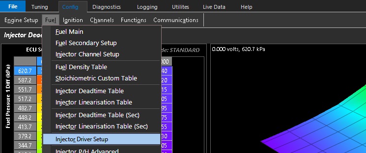
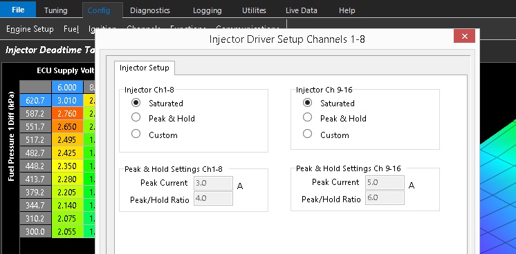
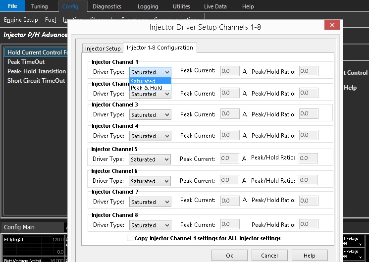
The Injector Driver Setup is where the injector driver output is configured.
For High Impedance or Saturated injectors the Saturated setting should be used
KV based ECU’s also have the ability for user defined Peak and Hold setting.
Peak & Hold refers to low impedance injectors that require significantly more current to run correctly
Peak and Hold Examples:
Peak Current = 4A
Peak/Hold Ratio = 4. This gives 4A/4 = 1A Hold Current
Peak Current = 6A
Peak/Hold Ratio = 6. This gives 6A/6 = 1A Hold Current
Peak Current = 6A
Peak/Hold Ratio = 1.5. This gives 6A/1.5 = 4A Hold Current
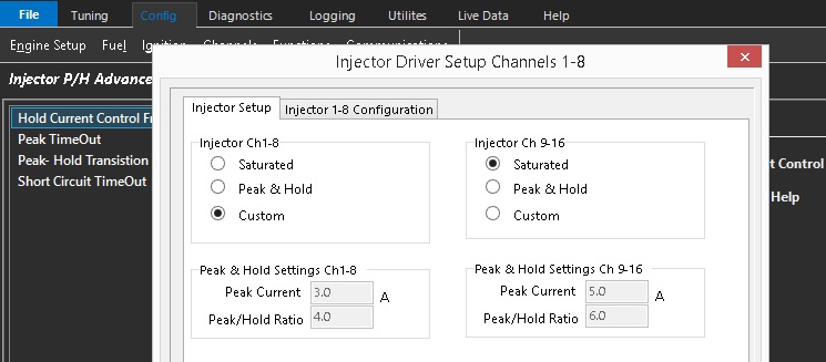
The Custom setting allows for individual injector channel setup
Injector Linearisation Table
Injector Linearisation Table
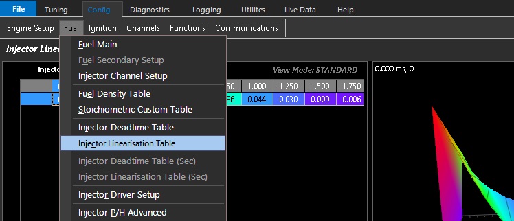
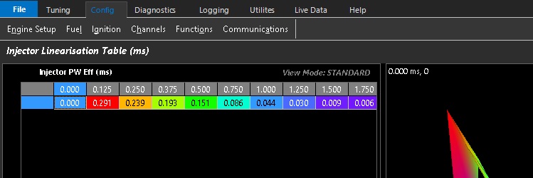
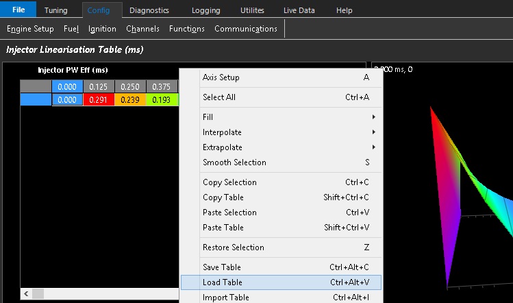
The Injector Linearisation table is a low pulse adder table which uses offset values that vary with pulsewidth, correcting the lower non linear operating range of the injector. Its only used a small pulsewidths and this data is available from most injector manufactures.
The Emtune software has commonly used Injector Linearisation Tables available in it that are only a right click of the mouse away
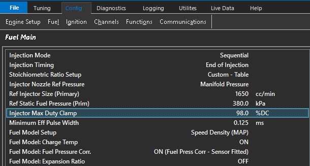
Injector Max Duty Clamp
Injector Max Duty Clamp
Clamps the Injector Duty Cycle.
NOTE:
The runtime Injector Duty will show past this value as it represents the duty cycle required to achieve the current pulse width.
This maximum duty clamp value applies to both primary & secondary injectors when using staged injection mode
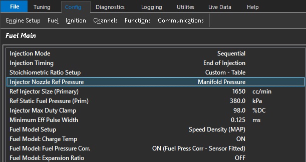
Injector Nozzle Ref Pressure
Injector Nozzle Ref Pressure
0: Manifold Pressure
1: Manifold Pressure - Bank 1
2: Manifold Pressure - Bank 2
3: Manifold Pressure Bank 1/2 Avg
4: Boost Pressure - Bank 1
5: Boost Pressure - Bank 2
6: Boost Pressure Bank 1/2 Avg
7: Barometric Pressure (Inj Before Plate)
Sets the reference against which injector differential pressure is measured
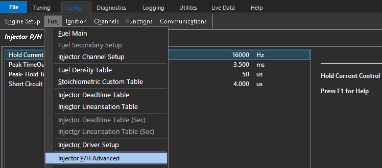
Injector P/H Advanced
Injector P/H Advanced
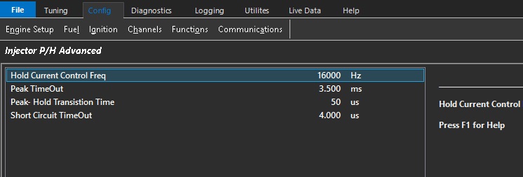
Injector Peak and Hold Advanced
This feature allows for user definable hold current & transition timing control of low impedance injector drivers
This is an advanced feature for experienced tuners only.
Ref Injector Size (Primary)
Ref Injector Size (Primary)
Flow rating of the primary injectors in cc per minute at the primary reference static fuel pressure
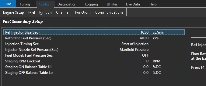
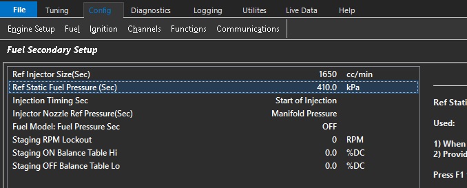
Ref Injector Size (Sec)
Ref Injector Size (Sec)
Flow Rating of the Secondary injectors
at the reference static fuel pressure
Ref Static Fuel Pressure (Prim)
Ref Static Fuel Pressure (Prim)
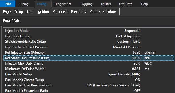
Reference static fuel pressure is set without the engine running at the current barometric pressure.
It is important that this setting is correct especially when the fuel pressure is enabled as part of the “fuel model”.
The ECU will correct the fueling if the fuel pressure goes above or below the differential fuel pressure.
The “Differential Fuel Pressure Offset” should be 0 or close to under normal operating conditions.
When “Fuel Model: Fuel Pressure” setting is ON
Provides a Diff Fuel Pressure Offset runtime.
Ref Static Fuel Pressure (Sec)
Ref Static Fuel Pressure (Sec)
Static reference pressure of secondary injectors
Secondary Injector Deadtime Table
The Injector Dead Time Table (Sec) is utilized by the ECU to compensate for the latency (or Deadtime) of the Secondary injectors
The injector deadtime is the time factor in milliseconds when no fuel is injected accounting for the reaction time of the injector.
Setting the correct deadtime of an injector is critical for ECU fuel mass calculations.
All injectors have a deadtime which may be affected by a number of factors.
The voltage at the injector generally has the highest influence on the injector deadtime.
Other factors such as fuel pressure also have a major affect on the injector deadtime.
Saturated injectors tend to have longer deadtimes when compared to peak & hold injectors
The Emtune software has commonly used Injector Deadtime Tables available in it that are only a right click of the mouse away.
Tuning Tip:
Secondary Injector Dead times can be validated using the Emtune Software by using the Wideband Lambda control. Once the secondary blend is biased 100% towards the secondary injectors. If you add 10% to your VE table (@ 3000rpm / 80kpa load for example), you should see a corresponding negative 10% trim applied via the Wideband lambda control. If you don’t, then you know your dead times need some attention.
By utilizing a dead time table available in your Emtune software that is close. The correct dead time for your injector can be quickly arrived at by simply globally moving the table up & down. The voltage slop of the dead times can be further validated by removing the alternator charge and allowing the supply voltage to drop away. Correct dead times allow the engine to operate correctly over a wide range of variable conditions
Starting Tables
Emtune has multiple tables for many engine functions. The table behavior is based on comprehensive selections in Tuning under the respective function (IE, Fuel, Ignition, DBW, Cam control). Some functions have many tables that can be enabled such as Fuel and Ignition tabs. These main functions allow you to enable a variety of compensations, modifiers, individual trims, and more.
For main table controls, the selections are mostly universal.
(Fuel example shown)
Not all of the above example will be available for every function, but generally most functions are the same.
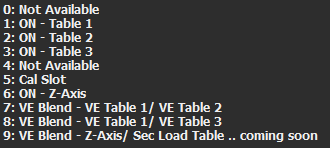
**ON – Table *** enable those respective tables always.
Cal Slot enables which table is currently being commanded by the Cal Slot Control (see Cal Slot Control)
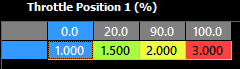
Z-Axis uses a separate X axis lookup that can allow the blending of all the available tables.
Any runtime can be used, and the units equal which table to run in this case. You can see in the above example the ECU will switch (and interpolate in between) the three different tables available based on TP1 position.
*** Blend** tables allow switching between two tables only.
Stoich Ratio Setup
Stoich Ratio Setup
Used as part of the Fuel Model in conjunction with the Lambda Target to determine the required Fuel Mass.
Units: AFR
0: Default: 14.70 AFR
1: Custom - Table
2: Gasoline
3: E85 Alcohol
4: E100 Alcohol
5: Methanol
6: Propane
7: Diesel
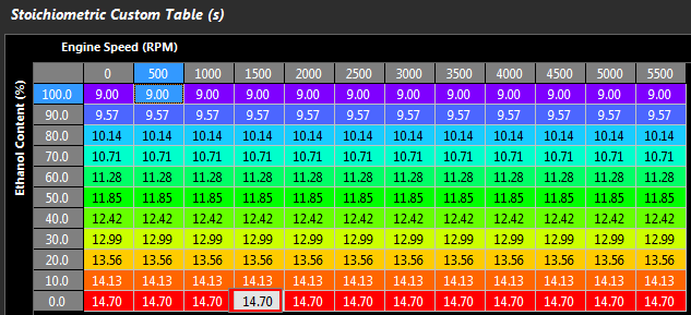
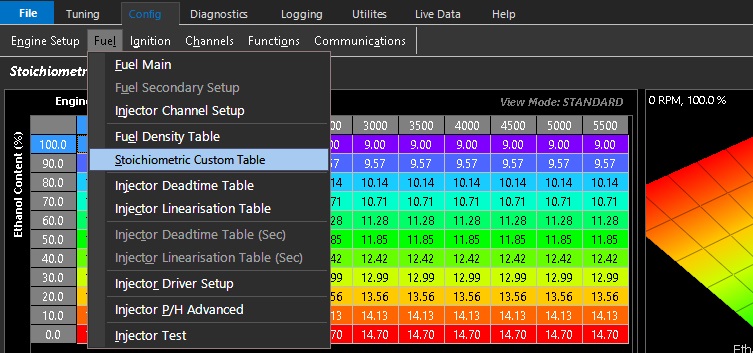
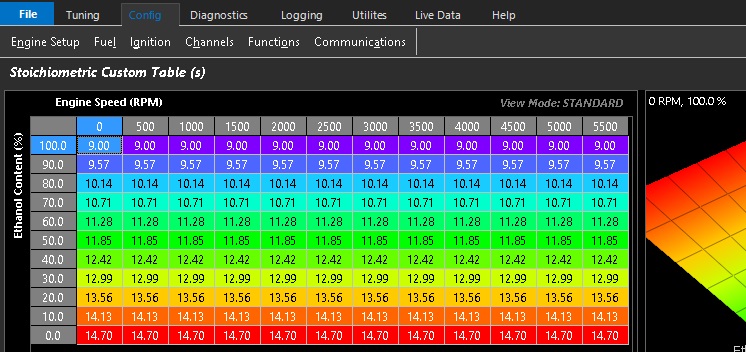
A custom table allow the user to adjust the Stoich in real-time as the Fuel-type changes. An Ethanol example is shown below.
Stoichiometric Custom Table
Stoichiometric Custom Table
Gasoline to Ethanol Stoichiometric Custom Table example shown - available to load in Emtune software
This table is used by the ECU to determine the stoichiometric fuel ratio.
This is critical when multiple fuel compositions are used.
The most common application of this table is in a multi fuel system which uses a flex meter to determine the alcohol content.