Ignition Channel Setup
Overview
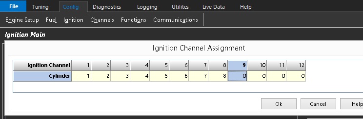
The Ignition Channel Setup table assigns each ECU ignition output channel to an engine cylinder number.
This configuration determines which ignition output is used to fire each cylinder.
A value of 0 indicates that the ignition output is not assigned to a cylinder and is therefore available for use by other ECU functions.
ℹ️ Note
The ignition channel assignments are independent of the engine firing order, which is configured separately using the Engine Firing Order settings. See Firing Order Setup
In most applications the ignition outputs are wired sequentially to simplify installation and diagnostics:
- Ignition Output 1 → Cylinder 1
- Ignition Output 2 → Cylinder 2
- Ignition Output 3 → Cylinder 3
- etc.
However, the ignition outputs may be assigned in any order to suit the wiring requirements of the installation.
Wasted Spark Configuration
For Wasted Spark applications, assign only the first cylinder in each firing pair to the ignition channel.
The ECU automatically determines the corresponding paired cylinder from the configured Engine Firing Order and generates the required wasted spark pairing and fills in the assignment table accordingly
The ignition channels should be assigned in engine firing order sequence.

Assign Ignition Channels as shown below (regarding above firing order). Enter cylinder 1 into Ignition Channel 1 and the ECU will automatically also assign its pair, cylinder 6. Likewise enter cylinder 5 into Ignition Channel 2 and the ECU will automatically assign its pair, cylinder 2 etc.
