Subsections of Ignition Configuration
Ignition Mode
Overview
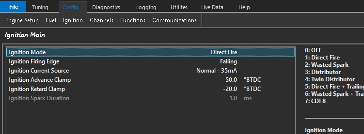
Selects the ignition output strategy used by the engine. The selected ignition mode determines how ignition events are distributed across the available ignition output channels.
⚠️ Warning
The ECU Ignition Output provides a TTL-level trigger signal intended to control an external ignitor or a coil with an integrated ignitor module.
Do not connect the ECU Ignition Output directly to a coil negative terminal. Incorrect connection will result in damage to the ECU and/or ignition system.
Options
| Value | Mode |
|---|---|
| 0 | Off |
| 1 | Direct Fire |
| 2 | Wasted Spark |
| 3 | Distributor |
| 4 | Twin Distributor |
| 5 | Direct Fire + Direct Trailing Spark |
| 6 | Wasted Spark + Direct Trailing Spark |
| 7 | CDI 8 |
Mode Descriptions
Off
Disables all ignition outputs.
Direct Fire
Each cylinder is assigned its own dedicated ignition output channel.
Wasted Spark
Each ignition output fires two cylinders simultaneously, with one spark occurring on the compression stroke and the other on the exhaust stroke.
Distributor
Uses a single ignition output to drive a conventional distributor ignition system.
Twin Distributor
Uses two ignition outputs to drive a twin distributor ignition system.
Direct Fire + Direct Trailing Spark
Provides individual ignition outputs for both leading and trailing spark plugs. Commonly used on rotary engines requiring independent control of leading and trailing ignition events.
Wasted Spark + Direct Trailing Spark
Uses wasted spark ignition for the leading plugs while maintaining individual control of the trailing spark plugs.
CDI 8
Configures the ECU for operation with an external 8-channel Capacitive Discharge Ignition (CDI) system.
ℹ️ Note
- Ignition Channel 1 is the only ignition output available in Distributor mode.
- Ignition Channels 1 and 2 are the only ignition outputs available in Twin Distributor mode.
- For Direct Fire + Direct Trailing Spark and Wasted Spark + Direct Trailing Spark modes, a maximum of 6 trailing ignition channels are available.
- All other ignition modes provide fully configurable ignition channel assignments.
See Ignition Channel Setup for channel setup help.
Ignition Firing Edge
Overview
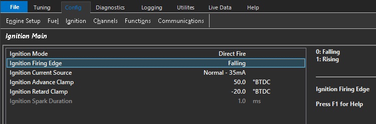
Selects the ignition output edge used by the ECU to trigger the ignition firing event.
The selected edge defines the polarity of the ignition control signal. One edge initiates coil charging (Dwell Edge) while the opposite edge commands the ignition coil to discharge and generate the spark (Firing Edge)
Warning.
Ensure the correct ignition edge is selected before connecting the ECU to the ignition system. Selecting the incorrect edge may result in damage to the ECU, ignition module, ignition coil(s), or associated wiring.
The ECU Ignition Output provides a TTL-level trigger signal intended to control an external ignitor or a coil with an integrated ignitor module.
Do not connect the ECU Ignition Output directly to a coil negative terminal. Incorrect connection will result in damage to the ECU and/or ignition system.
Options
| Value | Mode | Description |
|---|---|---|
| 0 | Falling | Coil charging begins on the Rising Edge and the spark is fired on the Falling Edge. |
| 1 | Rising | Coil charging begins on the Falling Edge and the spark is fired on the Rising Edge. |
ℹ️ Typical Configuration
Most modern ignition coils and ignition modules incorporate an internal ignitor and require a Falling Edge spark output.
Ignition MBT Reference
Overview
Selects the ignition table that represents MBT (Minimum Spark Advance for Best Torque).
MBT is defined as the ignition timing that produces the maximum engine torque for a given engine speed and load operating point. Additional ignition advance beyond MBT will typically provide little or no increase in torque, while ignition timing retarded from MBT will result in a reduction in engine torque output.
ℹ️ Why is MBT Required?
The ECU Engine Torque Model requires a reference for the ignition timing that produces maximum engine torque at each engine speed and load operating point. The selected MBT reference table provides this reference and defines the maximum available engine torque for the Engine Torque Model.
By comparing the active ignition timing against the MBT reference table, the ECU can determine when the engine is operating below its maximum torque potential due to ignition retard and apply the appropriate correction to the calculated engine torque.
The ECU continuously calculates the difference between the active ignition timing and the configured MBT reference table:
Where:
- 0° Offset = Engine operating at MBT torque.
- Negative Offset = Ignition timing is retarded relative to MBT, resulting in a reduction in the ECU calculated engine torque.
- Positive Offset = Ignition timing is advanced beyond MBT and will typically result in little or no increase in engine torque.
Options
| Value | Mode |
|---|---|
| 0 | Off |
| 1 | Table 1 |
| 2 | Table 2 |
Off
Disables MBT referencing. The Engine Torque Model assumes no torque reduction due to ignition retard.
Table 1
Uses Ignition Table 1 as the MBT reference table.
Table 2
Uses Ignition Table 2 as the MBT reference table.
ℹ️ Recap
When the MBT Offset becomes negative, the active ignition timing is retarded relative to the MBT reference timing. As a result, the ECU determines that the engine is operating below its maximum torque potential and applies a corresponding reduction to the calculated engine torque used by the Engine Torque Model.
The MBT reference table should represent the ignition timing required to achieve maximum engine torque.
If dual ignition tables are used for different fuel types, such as Petrol and E85, the ignition table representing the highest achievable engine torque should generally be selected as the MBT reference table.
Since E85 typically requires greater ignition advance to achieve MBT than an equivalent Petrol calibration, the E85 ignition table will often be the preferred MBT reference.
Dwell Setup
Dwell Setup
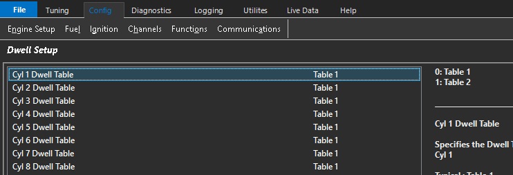
Overview
There are two Dwell Tables available. This setting determines which Dwell Table is assigned to each cylinder.
In most applications all cylinders will use the same Dwell Table. However, multiple dwell tables can be useful when different ignition coil types are used, or when leading and trailing ignition systems require different dwell characteristics.
Dwell Tables
Overview
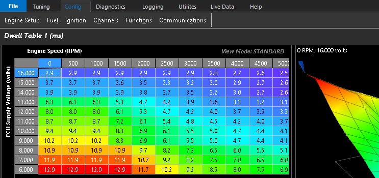
The Dwell Table defines the ignition coil charge time (dwell) as a function typically of ECU Supply Voltage and Engine Speed.
Dwell time is the amount of time the ignition coil primary winding is energised prior to the spark event and is expressed in units of milliseconds (ms).
During the dwell period, energy is stored within the ignition coil magnetic field and is subsequently released when the ignition event occurs. Insufficient dwell time may result in a weak spark and ignition misfire, while excessive dwell time can overheat the ignition coil and ignition driver circuitry.
Two independent Dwell Tables are available and can be assigned to individual cylinders using the Dwell Setup configuration page. See Dwell Setup for more infomration.
ℹ️ Note
Excessive dwell time does not generally increase spark energy once the ignition coil has reached magnetic saturation and may result in unnecessary heating and/or failure of the ignition coil and ignition drivers.
Dwell Offset Table 1
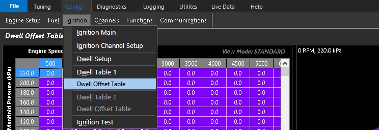
The Dwell Offset Table 1 is a user-defined offset table that allows ignition coil charge time (dwell) to be adjusted based on operating conditions or factors not directly accounted for by Dwell Table 1.
Final Dwell = Dwell Table 1 + Dwell Offset Table 1
ℹ️ Note
Dwell Table 1 supports a user-defined Dwell Offset Table. Dwell Table 2 does not have an associated offset table and uses the base dwell values defined within the table only.
Ignition Test
Overview
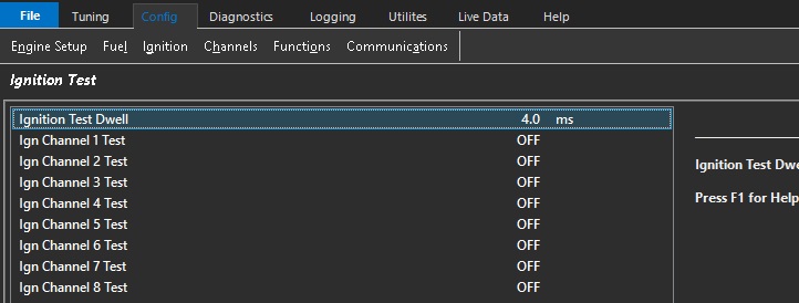
The Ignition Test function allows each ignition output channel to be manually fired for installation, diagnostics and troubleshooting purposes.
This function can be used to:
- Verify ignition coil wiring.
- Confirm cylinder numbering and firing order.
- Check ignition output operation.
- Verify spark plug and ignition coil functionality.
- Diagnose ignition system faults.
The Ignition Test Dwell setting specifies the coil charge time used during the test event and is expressed in units of milliseconds (ms). A test dwell value of 3.0 to 4.0 ms is suitable for most modern inductive ignition coils.
When an ignition channel test is activated, the ECU charges the selected ignition coil for the configured test dwell period before firing a spark event. The test rate runs at 10Hz
The ignition test function operates at a fixed test rate of 10 Hz (10 ignition events per second).
⚠️ Warning
The Ignition Channel Output must have a cylinder assigned for this function to operate. See See Ignition Channel Setup for help.
Ensure the ignition system is configured correctly before performing an ignition test.
High voltages are generated during ignition testing which may cause injury or damage to ignition components if used incorrectly.
Do not perform ignition tests in the presence of fuel vapour or near flammable materials.
Ignition Channel Setup
Overview
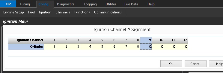
The Ignition Channel Setup table assigns each ECU ignition output channel to an engine cylinder number.
This configuration determines which ignition output is used to fire each cylinder.
A value of 0 indicates that the ignition output is not assigned to a cylinder and is therefore available for use by other ECU functions.
ℹ️ Note
The ignition channel assignments are independent of the engine firing order, which is configured separately using the Engine Firing Order settings. See Firing Order Setup
In most applications the ignition outputs are wired sequentially to simplify installation and diagnostics:
- Ignition Output 1 → Cylinder 1
- Ignition Output 2 → Cylinder 2
- Ignition Output 3 → Cylinder 3
- etc.
However, the ignition outputs may be assigned in any order to suit the wiring requirements of the installation.
Wasted Spark Configuration
For Wasted Spark applications, assign only the first cylinder in each firing pair to the ignition channel.
The ECU automatically determines the corresponding paired cylinder from the configured Engine Firing Order and generates the required wasted spark pairing and fills in the assignment table accordingly
The ignition channels should be assigned in engine firing order sequence.

Assign Ignition Channels as shown below (regarding above firing order). Enter cylinder 1 into Ignition Channel 1 and the ECU will automatically also assign its pair, cylinder 6. Likewise enter cylinder 5 into Ignition Channel 2 and the ECU will automatically assign its pair, cylinder 2 etc.

Ignition Main
Overview
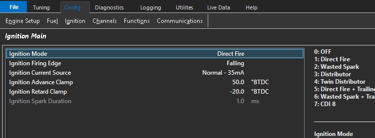
Ignition Main allows for configuring the ECU to suit the engine’s ignition system.
The following settings are configured in this menu item :
- Ignition Mode
- Ignition Firing Edge
- Ignition Current Source
- Ignition Advance Clamp
- Ignition Retard Clamp
- Ignition Spark Duration
⚠️ Warning
The ECU Ignition Output provides a TTL-level trigger signal intended to control an external ignitor or a coil with an integrated ignitor module.
Do not connect the ECU Ignition Output directly to a coil negative terminal. Incorrect connection will result in damage to the ECU and/or ignition system.
Ignition Mode
See Ignition Mode for help.
Ignition Firing Edge
See Ignition Firing Edge for help.
Ignition MBT Reference
See Ignition MBT Reference for help.
Ignition Current Source
Controls the available current drive capability for all Ignition Channels
The ECU provides two selectable ignition output current modes:
- Standard Current Mode 35mA at 5V
- High Current Mode 70mA at 8.2V
High Current mode provides increased drive capability for ignition systems that require a higher input current (for example one ignition output driving two ignitors).
Ignition Advance Clamp
Limits the maximum ignition advance that the ECU is permitted to command.
If the final ignition timing calculation exceeds this value, the ignition timing will be clamped to the configured advance limit.
This function can be used to protect the engine from excessive ignition advance due to calibration errors, sensor failures or unexpected operating conditions.
Example:
- Calculated Ignition Timing = 49°
- Ignition Advance Clamp = 45°
Final Ignition Timing = 45°
Ignition Retard Clamp
Limits the maximum ignition retard that the ECU is permitted to command.
If the final ignition timing calculation is retarded beyond this value, the ignition timing will be clamped to the configured retard limit.
This limit is applied to the final ignition timing calculation after all ignition corrections, compensations and modifiers have been applied.
Allowing sufficient ignition retard range is important for functions that intentionally reduce engine torque using ignition timing retard, for example traction control, launch control and anti-lag etc.
A typical value for this setting is -45° BTDC.
Ignition Spark Duration
Specifies the minimum off-time after an ignition firing event before the ignition coil is permitted to begin charging again.
This ensures the coil remains de-energised long enough for the energy from the previous spark event to fully dissipate before the next dwell period begins.
This setting only applies when the ignition mode is configured as Distributor or Twin Distributor.
Default: 1.0 ms
Ignition Retard Clamp
Ignition Retard Clamp
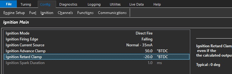
The minimum ignition timing allowed even if the the calculated output is lower .
Typical : -20 deg
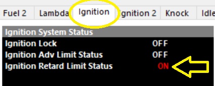
The ECU also provides a Status flag to indication this condition. Open the ECU Runtimes menu (F3) and select the Ignition Tab.
Ignition Spark Duration
Ignition Spark Duration
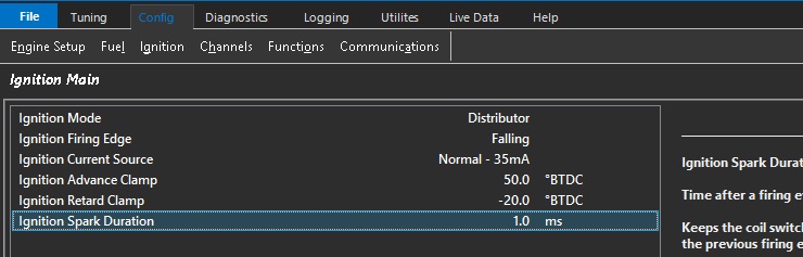
The user definable time factor after a firing event before the coil can be switched back on.
This function keeps the ignition coil switched off for a fixed time, allowing the energy from the previous firing event to fully discharged.
Default: 1.0ms
0.5ms to 5.0ms time window available
Note: Distributor systems only