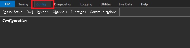
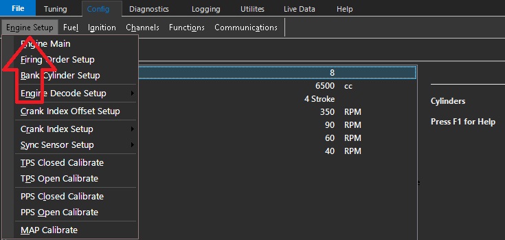
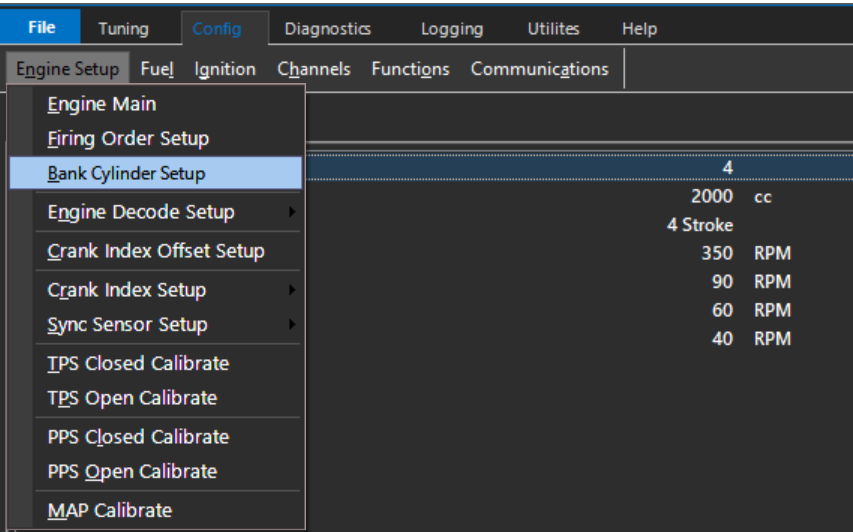
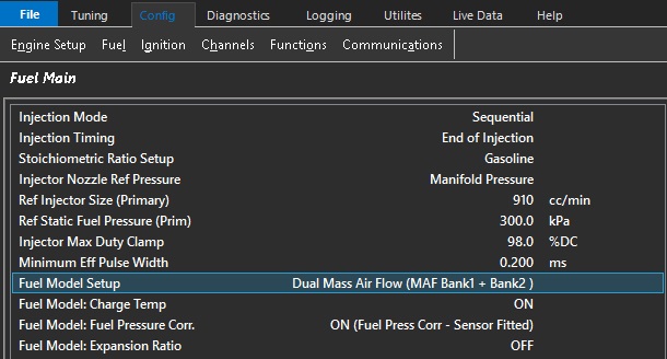
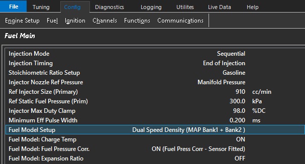
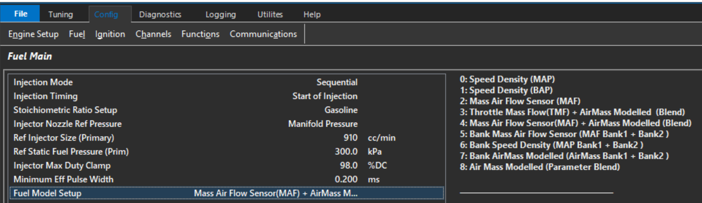
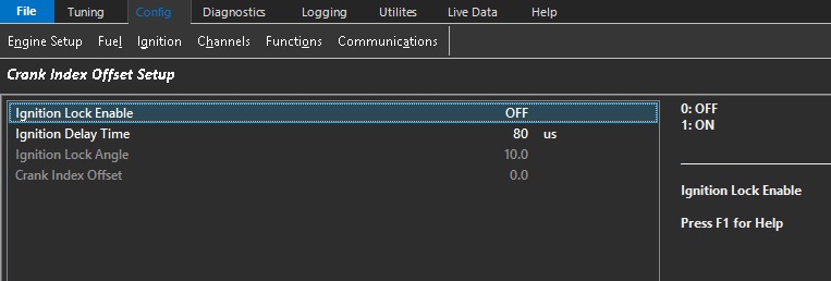
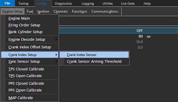
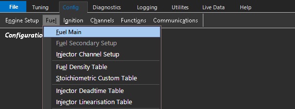
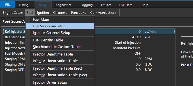
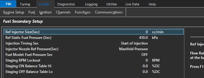
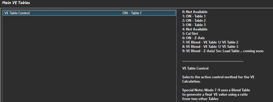
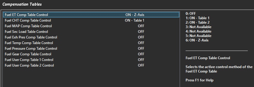
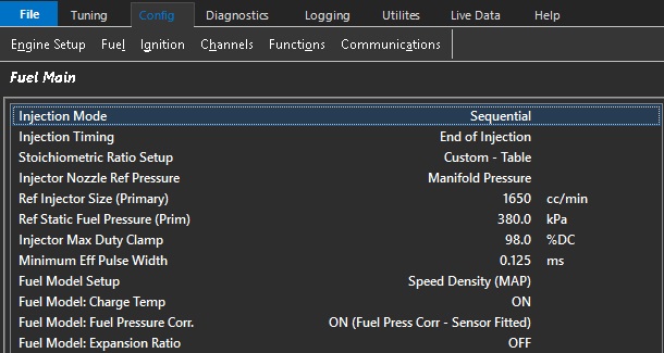
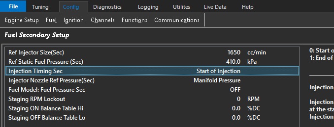
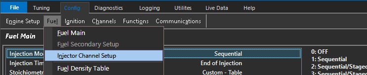
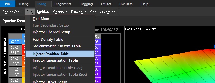
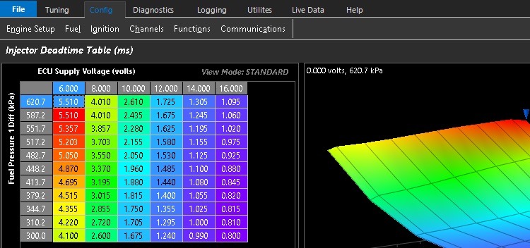
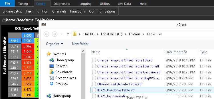
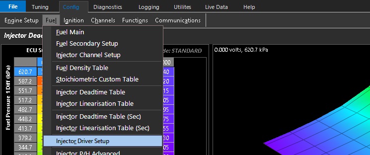
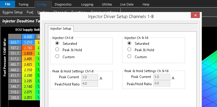
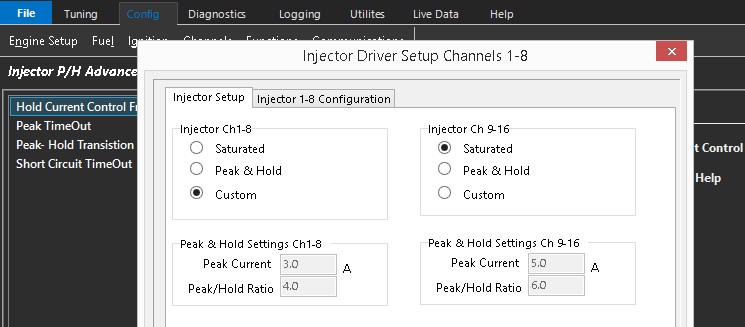
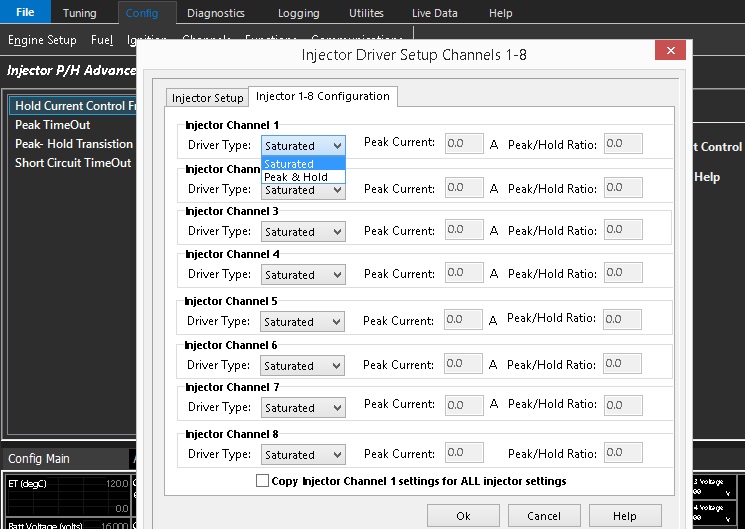
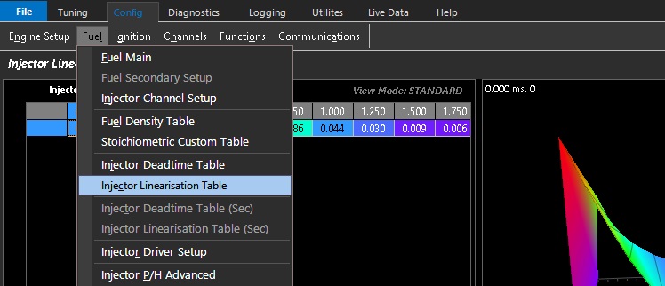
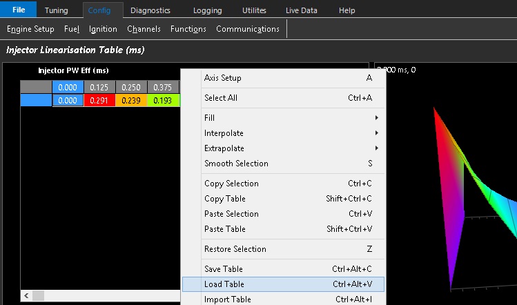
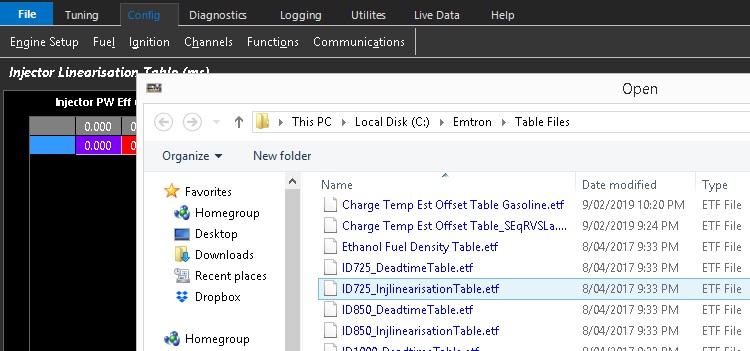
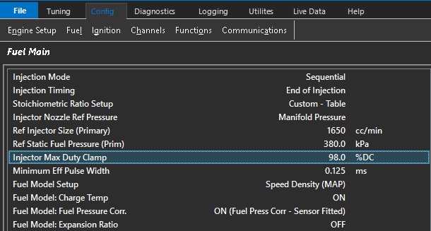
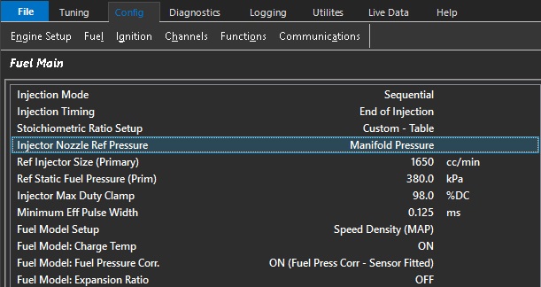
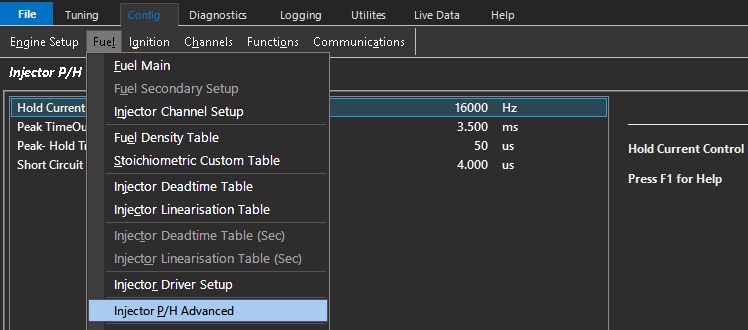
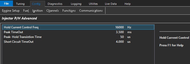
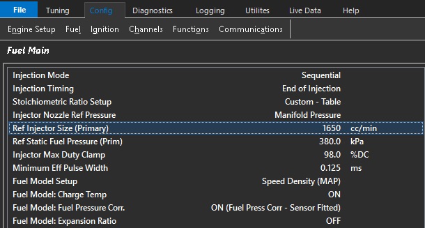
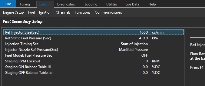
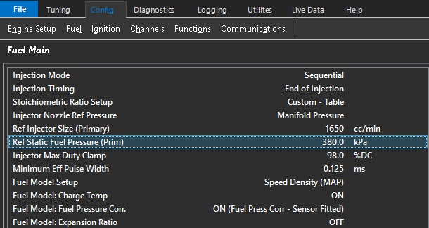
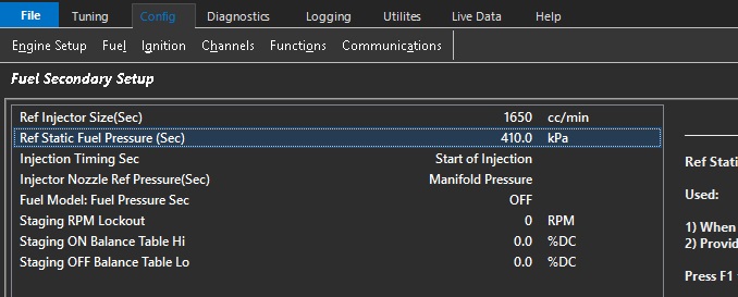
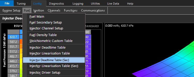
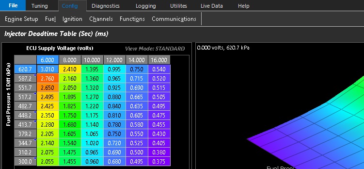
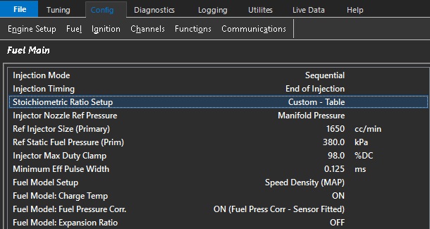
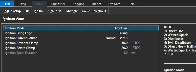
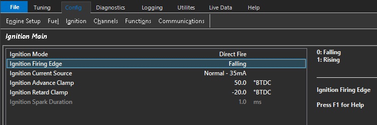
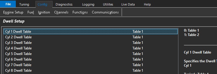
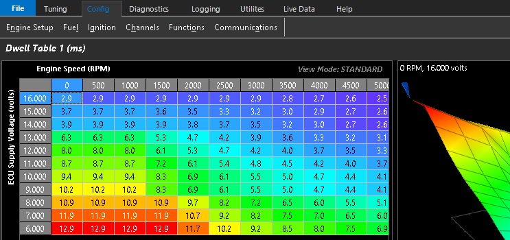
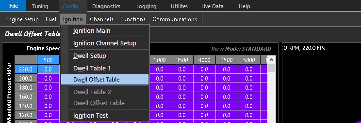
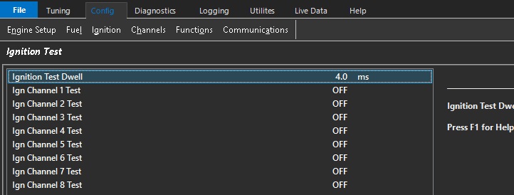
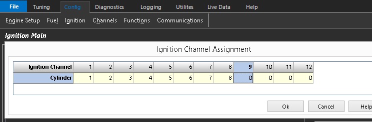
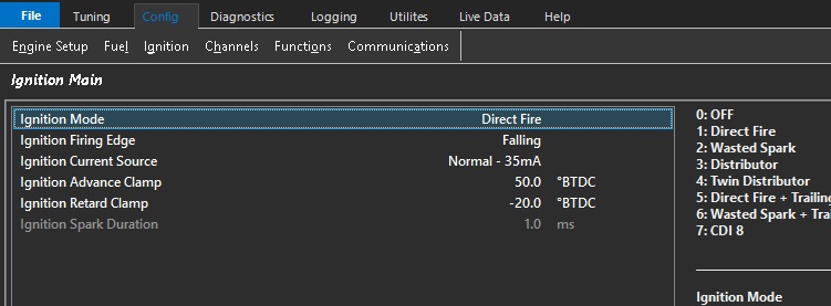
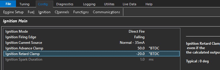
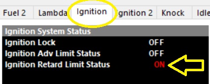
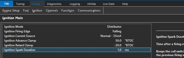
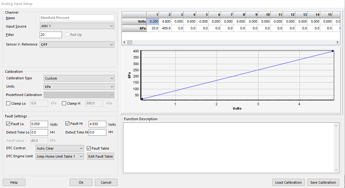
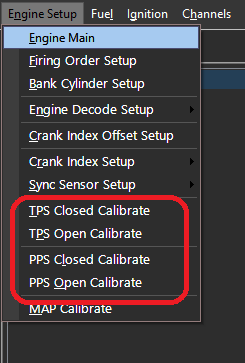
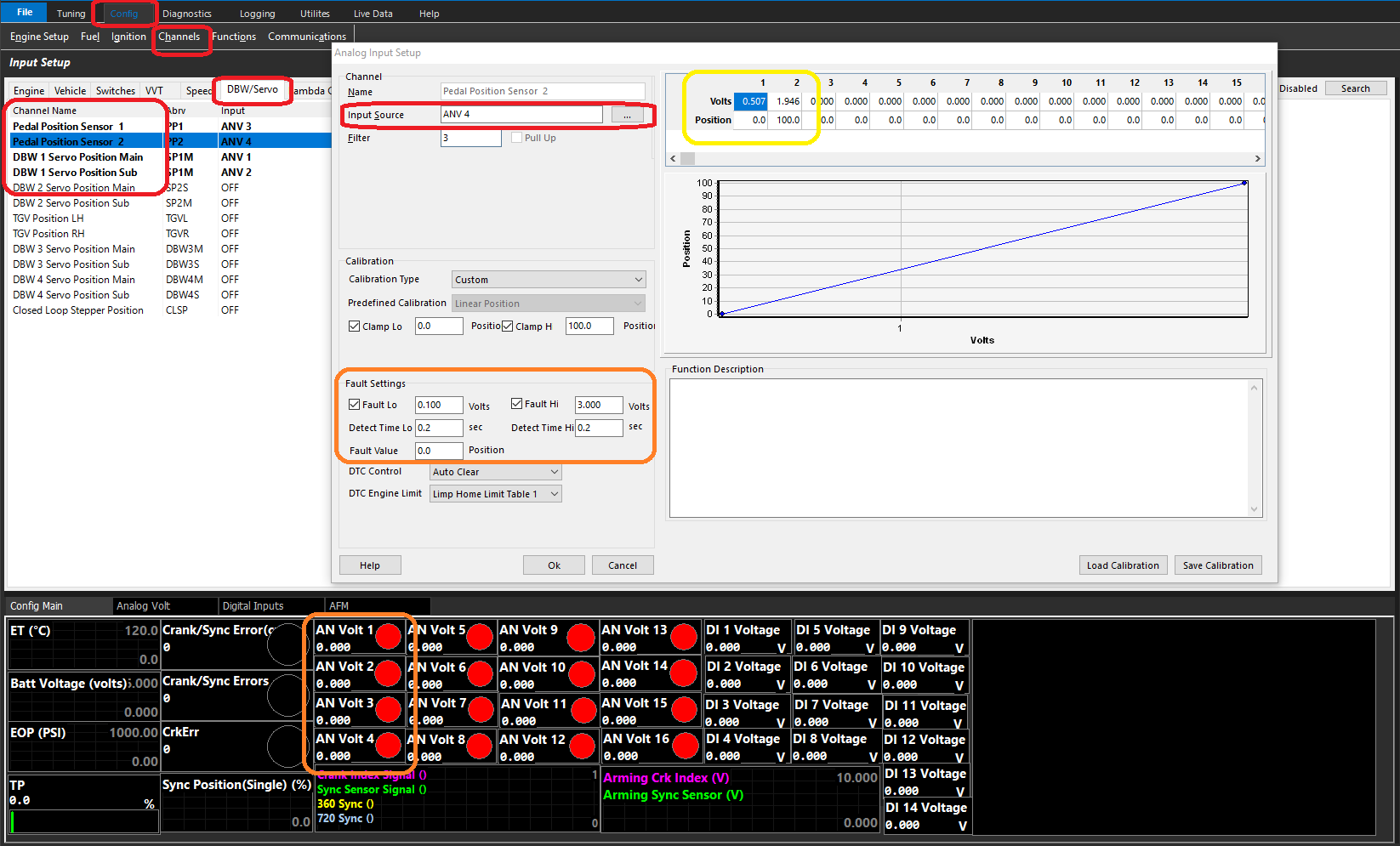
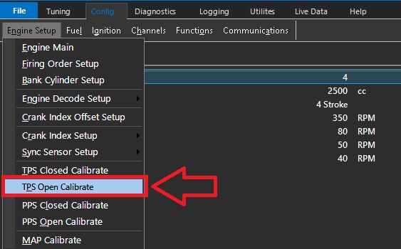
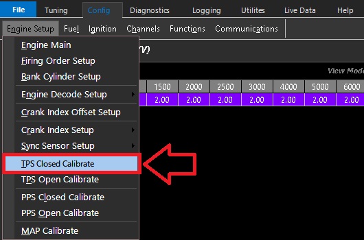
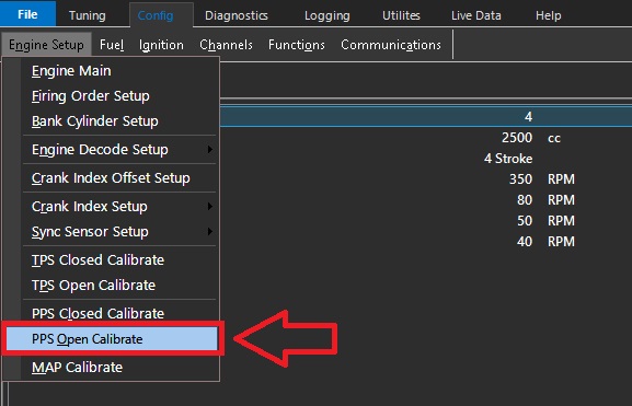
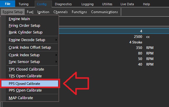
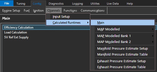
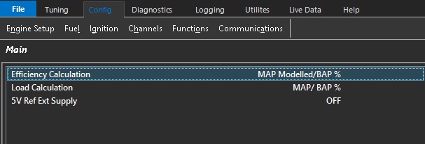
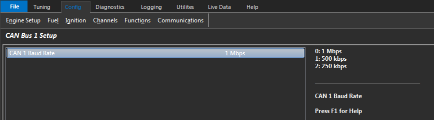
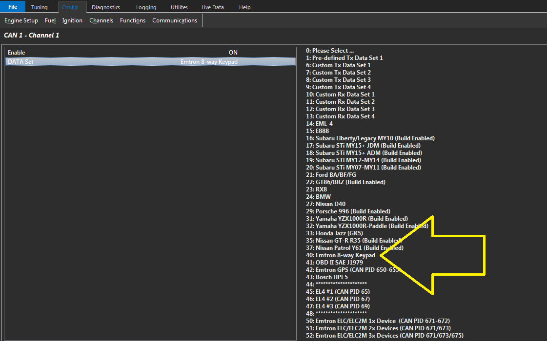
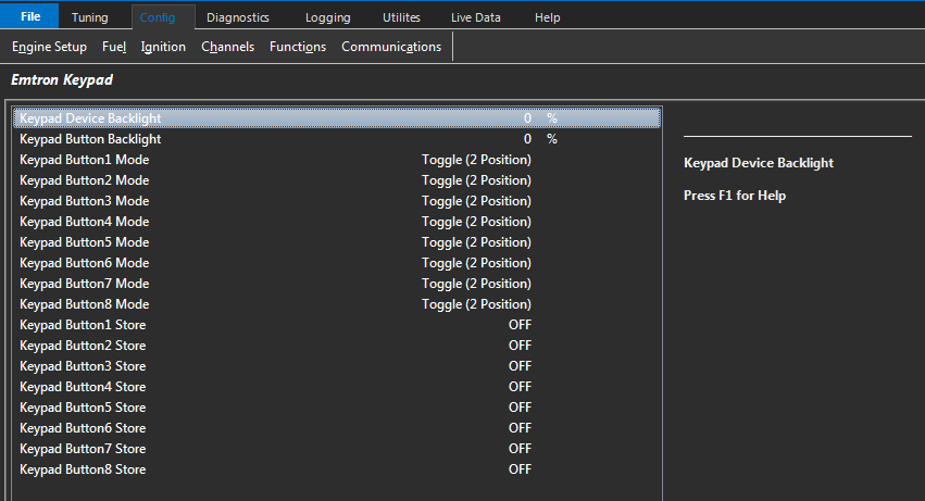
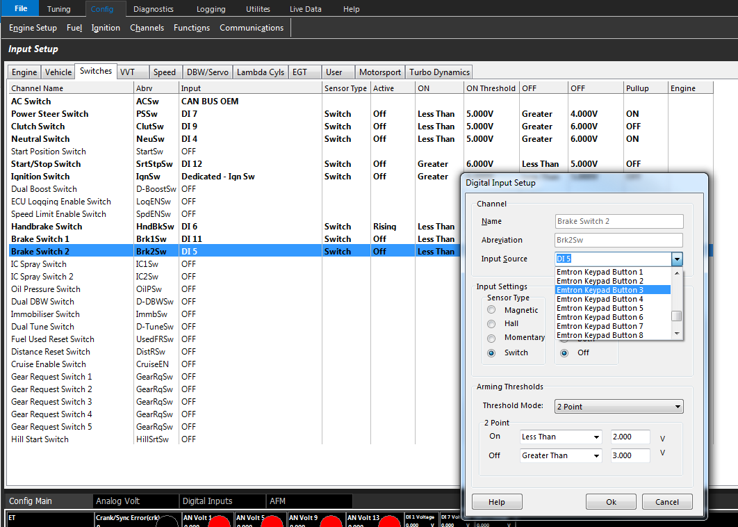
To enter the ECU configuration, click the Config tab at the top. This will give access the the Engine Setup, Fuel, Ignition, Channels, Functions & Communications tabs
The Emtune software has a very systematical approach to configuration. Start on the left side “Engine Setup”, and work your way over from left to right.
Do not skip sections. Following this practice as accurately as possible will ensure tuning process will move smoothly in the future.
WARNING: Incorrect configuration or entry of any setup parameter may result in damage to the ECU electronics or connected hardware.Tuning Tips:
Any increases to the accuracy of the information entered into the configuration of the ECU, will serve to reduce the level of calibration error.
The importance of accurate configuration cannot be overstated when the project is to be Torque Modelled. Take the time to ensure all configuration entries are based on accurate, verified information. For example, if an engine is described as a 6.2 litre engine but the actual displacement is 6162 cc, the actual value of 6162 cc should be entered. Using an assumed or rounded value introduces an error into the Engine Model that must then be accounted for during calibration.
Minimising errors during the configuration stage reduces the calibration error that must be addressed during engine tuning. This applies to all configuration parameters, not just engine displacement. In short, if you put the effort into the configuration, your job will be easier when it comes to tuning.*
Emtune has a very systematical approach to configuration.
Start on the left side “Engine Setup”, and work your way over from left to right.
Do not skip sections. Following this practice as accurately as possible will ensure tuning process will move smoothly in the future.
Improper entry in any part of the setup could be detrimental to the electronics AND the hardware!
Setup each tab from top to bottom. See help file for explanation of each individual function, as well as help text in the respective configuration screens.
**Crank index offset MUST always be checked regardless of trigger pre-configuration.
This setting defines the two engine cycle type supported by the ECU.
4-Stroke – The most common engine type. One complete engine cycle occurs over two crankshaft revolutions (720°).
2-Stroke – One complete engine cycle occurs over one crankshaft revolution (360°).
Rotary engines are regarded as 2 stroke engines
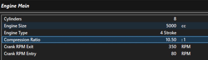
Engine Size
The total engine displacement, entered in cc. Enter the exact displacement; do not round this value.
: Important Note: This setting is critical and must be configured accurately, as engine displacement is used by the ECU in various calculations that form part of the engine model. An incorrect engine displacement can therefore affect the accuracy of multiple calculated parameters, including Air Mass and Engine Torque.
i.e Do not round this setting, use the exact displacment.
Compression Ratio
This value is the static compression ratio of the engine. ie: Swept volume over clearance volume.
This setting is used to 2 important calculations:
Used to calcaulte the Clearance Volume which forms part of the Expnansion Ratio calcuation. See Speed Density: VE Expansion Ratio for more infomration
Used by the Engine Torque Model to account for the effect of engine compression on the conversion of combustion energy into torque. See Torque Model for more infomration.
Crank RPM Entry
Used to determine the Engine Speed which is considered as cranking. Various compensations also use this value to determine when to be enabled.
The value entered must be low enough at cranking speeds to ensure the cranking compensations can be enabled.
Crank RPM Exit
Defines the engine speed above which the engine is considered to be running. Various compensations also use this value to determine when they should be enabled.
NOTE: Should you have an engine that is difficult to initially cold start, that is it doesn’t start on first crank, rather on the second or third attempt, then increasing the Crank RPM Exit in some instances can help. This allows the engine to utilize the Crank Comp Table for a little longer allowing for a faster start and quicker handover to a run condition.
Tuning Tip. Any increase in the accuracy of the information entered into the ECU configuration will help reduce calibration error.
The importance of entering the correct engine information cannot be overstated if the project is to be torque modelled. Extra time should be spent to ensure that all configuration entries are accurate.
For example, if an engine is described as a 6.2-litre engine but its actual capacity is 6162 cc, the correct value of 6162 cc should be entered. Any errors introduced during the configuration stage will carry through into the tuning process and contribute to calibration error.
This applies to all configuration entries, not just engine capacity. In short, the more effort you put into getting the configuration correct, the easier and more accurate the tuning process will be.
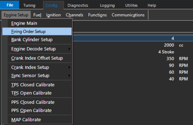
Firing Order Setup
Firing Order Setup
This table is used to define the engine firing order and the base angle for each cylinder.
Most engines are even-fire, meaning that each firing event occurs at an equal crankshaft angle from the previous firing event.
For example, a 4-cylinder, 4-stroke, even-fire engine commonly uses a firing order of 1-3-4-2.
The corresponding base angles are: 0° – 180° – 360° – 540°
For even-fire engines, the Generate Base Angles function can be used to automatically calculate the base angles once the firing order is entered.
For odd-fire engines, the base angles are not equally spaced and must be entered manually, as shown below for a Dodge Viper application.
Bank Cylinder Setup
Bank Cylinder Setup
Assigns each cylinder to Bank 1 or Bank 2. This allows the ECU to determine which cylinders the bank-specific fuel or ignition trims are applied to.
The Air Mass Model defines how the ECU calculates the mass of air entering the engine.
Accurate air mass calculation is critical for two primary functions within the ECU:
The calculated air mass is used to determine the required fuel mass to achieve the commanded Lambda Target, before being converted into an injector pulse width using the injector configuration data.
The calculated air mass is used by the Engine Torque Model to estimate engine torque. Accurate air mass calculation is therefore essential to ensure Torque Control and Torque Reduction functions operate correctly.
Important Note: Torque and Air Mass.
The selected Air Mass Model forms the foundation of the ECU Fuel and Torque calculations and should be configured before starting engine tuning.
Just to restate this important point, the ECU calculates engine torque from the Air Mass defined by the Mass Model. This may be derived from Speed Density, TMF, a Mass Air Flow (MAF) Sensor, or another supported air-mass measurement method. The importance of correctly calibrating the selected Air Mass Model cannot be overstated. Accurate air mass modelling is fundamental to achieving accurate engine torque modelling and, consequently, correct operation of the ECU’s Torque Control and Torque Reduction functions.
Throttle Torque Reduction can only operate when the Air Mass Model Throttle Mass Flow (TMF) is enabled. TMF is required to accurately calculate the change in air mass across the throttle plate during throttle movements and can therefore provide accurate throttle torque reduction control.
The Throttle Mass Flow (TMF) air mass model cannot be used as a standalone air mass calculation and must always be blended with a secondary air mass model. At throttle pressure ratios above 0.9 (Post-Throttle Pressure / Pre-Throttle Pressure), the pressure differential across the throttle body becomes very small, significantly reducing the sensitivity and resolution of the TMF calculation. This requirement is referenced multiple times throughout the documentation due to its importance when configuring TMF based air mass models.
Different engine combinations may benefit from different air mass calculation strategies. Emtron provides several Air Mass Models to suit a wide range of applications. The ECU can calculate engine air mass using the following Air Mass Models:
Setup Options
Value
Air Mass Model
0
Speed Density (MAP)
1
Speed Density (BAP)
2
Mass Air Flow (MAF)
3
Air Mass User 1 + Throttle Mass Flow (TMF) Blend
4
Speed Density (MAP) + Throttle Mass Flow (TMF) Blend
5
Emtron Air Mass Model (Custom)
Air Mass Model Descriptions
Speed Density (MAP)
Calculates engine air mass using the Ideal Gas Law based on Manifold Absolute Pressure (MAP), Charge Temperature, Engine Displacement, and Volumetric Efficiency (VE).
Calculates engine air mass using Barometric Absolute Pressure (BAP) instead of manifold pressure. This mode is typically used on naturally aspirated engines operating with individual throttle bodies (ITBs), where manifold pressure is not a reliable indicator of engine load.
The final engine air mass is generated by blending the calculated Air Mass User 1 value and Throttle Mass Flow (TMF) calculation using the ratio defined by the Air Mass Blend Table.
When this mode is enabled the The Air Mass Blend Table becomes active: Tuning -> Fuel -> Air Mass Model Blending Table
Speed Density (MAP) + Throttle Mass Flow (TMF) Blend
The final engine air mass is generated by blending Speed Density (MAP) value and Throttle Mass Flow (TMF) calculation using the ratio defined by the Air Mass Blend Table.
When this mode is enabled the The Air Mass Blend Table becomes active: Tuning -> Fuel -> Air Mass Model Blending Table
At throttle pressure ratios above approximately 0.9 (Post-Throttle Pressure / Pre-Throttle Pressure), the pressure differential across the throttle body becomes very small, reducing the resolution of the Throttle Mass Flow (TMF) calculation. This is why TMF must always be blended with an alternative air mass calculation method and cannot be used as the sole air mass model for engine operation.
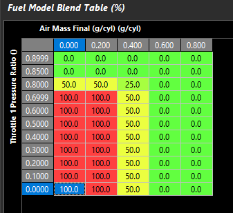
The Air Mass Blend Table should therefore progressively transition from TMF to an alternative air mass calculation method as the throttle pressure ratio approaches 1.0
The Air Mass Blend Table forms part of the engine air mass model and must be finalised before tuning starts.
The TMF Correction Table can be used to make small adjustments to the TMF calculation if required. In most applications, little or no correction should be necessary.
Emtron Air Mass Model (Custom)
Uses the custom Emtron air mass model. See here for more information: Emtron air mass
Air Mass Blend Table
When Air Mass Model 3, 4 or 5 is selected, the Air Mass Blend table is enabled.
This table determines the contribution(ratio) of each air mass model used to calculate the final engine air mass.
Intermediate values proportionally blend between the selected air mass models.
This option is only available using the Emtron Air Mass Model. See Emtron Air Mass Model
Air Mass Runtimes
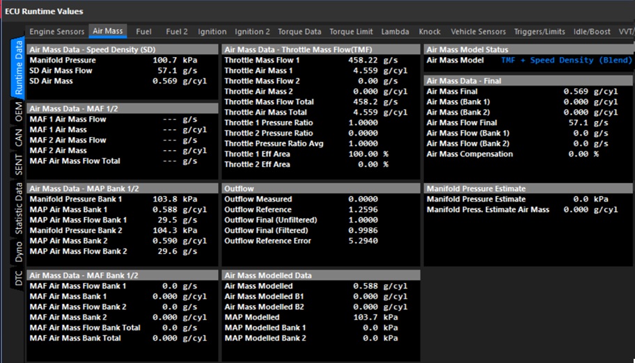
All ECU air mass related runtimes can be viewed from: ECU Runtime -> Air Mass
Note on Units: Air Mass Flow is expressed in units of g/s (grams per second), while Air Mass is expressed in units of g/cyl (grams per cylinder), representing the mass of air trapped in the cylinder during a single engine cycle.
Speed Density (BAP)
Speed Density (BAP Sensor)
Speed Density (BAP) mode is predominantly used in TPS only tuning methods.
This mode uses the same Fuel Model and equations as listed for mode 0 (Speed Density (MAP)), the only difference is the MAP sensor is replaced with the BAP sensor.
Speed Density (MAP)
Overview
The ECU’s primary Air Mass Model is Speed Density (MAP Sensor).. The basis of this calculation is derived using the Ideal Gas Law; PV = nRT
The ECU calculates the injection time for speed density using the following information:
Displacement volume per cylinder (cc).
Intake Manifold Air Pressure - MAP(kPa)
Lambda Target (La)
Stoichiometric Ratio of the Fuel (Stoich)
Injector Flow rate (cc/min)
Charge Temperature (DegC)
Fuel Density (g/ml)
Fuel Pressure (kPa)
Engine VE (%)
Gas Constant - R = 287J/Kg/K for Dry Air.
Using these inputs, the ECU calculates the mass of air trapped within each cylinder for every engine cycle. The calculated air mass is then used to determine the required fuel mass to achieve the commanded Lambda Target, before being converted into an injector pulse width.
Important Note
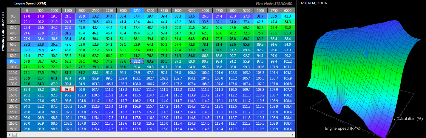
Since the air mass is calculated rather than measured directly, the accuracy of the Speed Density model depends heavily on correct calibration of the Volumetric Efficiency (VE) table(s).
In the predefined Speed Density (MAP) Air Mass Model, the pressure source is fixed to the Manifold Pressure input channel and cannot be changed.
If an alternative pressure source is required, this is only available when using the Emtron Air Mass Model (Mode 5):
Set Air Mass Model = Emtron Air Mass Model
Configure Calculation 1 or Calculation 2 as Speed Density
Configure the desired pressure source from: Config → Air Mass → Speed Density Setup → Speed Density MAP Source
Speed Density Setup
The Speed Density setup parameters are configured from: Config → Air MAss → Speed Density (SD) Setup
The following settings are used to configure the Speed Density Air Mass Model.
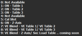
VE Table Control
Selects the method used to generate the final Volumetric Efficiency (VE) value used by the Speed Density calculation (Non-Banked Mode).
This setting is only available when the selected Air Mass Model uses Speed Density.
Value
Mode
0
Not Available
1
Table 1
2
Table 2
3
Not Available
4
Cal Slot
5
Not Available
6
Z-Axis
7
VE Blend (VE Table 1 / VE Table 2)
Table 1: Uses VE Table 1 exclusively for all engine operating conditions.
Table 2: Uses VE Table 2 exclusively for all engine operating conditions.
Cal Slot: Allows the active VE table to be switched dynamically in real time using the Calibration (Cal) Slot Table function. See : Tuning → Cal Control
Z-Axis: Enables a user configurable third operating axis to blend or switch between VE Table 1 and VE Table 2. The Z-axis can use any available ECU runtime making it suitable for applications such as:
Variable camshaft systems (VTEC/VVL)
Alternate fuel calibrations
VE Blend: Uses the VE Blend Table to generate the final VE value by blending between VE Table 1 and VE Table 2.
0.0% = All VE Table 1
50.0% = Equal blend of VE Table 1 and VE Table 2
100.0% = All VE Table 2
Speed Density Charge Temperature Enable
When enabled, the ECU includes Charge Temperature in the Speed Density air mass calculation. The ECU automatically corrects the calculated air mass based on Charge Temperature Estimate using the Ideal Gas Law. For this reason, the Charge Temperature Compensation Tables should initially be configured to zero (not used).
When disabled, the Speed Density model assumes a fixed charge temperature of 20°C and the Charge Temperature Compensation Tables are therefore required to provide the necessary fuel compensation.
Recommended Setting: ON
VE Expansion Ratio
The VE Expansion Ratio feature uses the relationship between:
Exhaust Manifold Pressure (EMAP)
Manifold Absolute Pressure (MAP)
Engine Static Compression Ratio
to correct the effective volumetric efficiency of the engine as exhaust backpressure changes.
NOTE: VE Expansion Ratio correction operates only when the Air Mass Model is configured for Speed Density mode as this is a VE correction.
This is particularly beneficial on turbocharged engines operating at high boost pressures where increasing exhaust backpressure can significantly influence cylinder filling efficiency.
Selects the pressure source used by the Speed Density calculation. This setting is ONLY available when the selected Air Mass Model is Emtron Air Mass Model.
For all predefined Air Mass Models this setting defaults to the Manifold Pressure input and cannot be modified.
The following pressure sources are available:
Value
Pressure Source
0
Off
1
Barometric Pressure
2
Manifold Pressure
3
Manifold Pressure - Bank 1
4
Manifold Pressure - Bank 2
5
Manifold Pressure - Bank 1 / 2 Average
6
Boost Pressure
7
Boost Pressure - Bank 1
8
Boost Pressure - Bank 2
9
Boost Pressure - Bank 1 / 2 Average
10
MAP Estimate
11
User Pressure 1
12
User Pressure 2
13
User Pressure 3
14
User Pressure 4
Speed Density MAP Bank 1 and Bank 2 Source.
Selects the pressure source used for each individual bank Speed Density calculation.
This setting is only available when:
The selected Air Mass Model is Emtron Air Mass Model
Air Mass Bank Control is enabled
The same pressure source options described in Speed Density MAP Source are available for both Bank 1 and Bank 2 calculations.
Example:
MAP = 252kPa
Charge Temperature = 30.7 DegC
Volume Per Cylinder = 666.6
Stoich Ratio = 9.9
Lambda Target = 0.785
Engine VE = 96.6 %
Fuel Mass (g) = 0.2395
In this basic example, if the cylinder achieves 96.6% volumetric efficiency, then 0.2395 grams of fuel is required to achieve a Lambda Target of 0.785.
The VE Table(s) define the volumetric efficiency of the engine at varying engine speeds and loads and represent the True VE of the engine. A typical table is shown in Figure 1 for a turbo charged engine.
Fuel VE Table
Figure 1
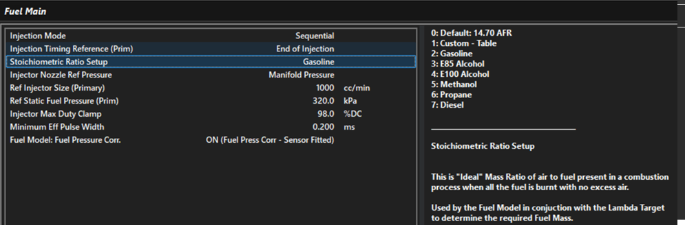
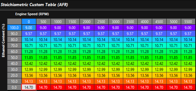
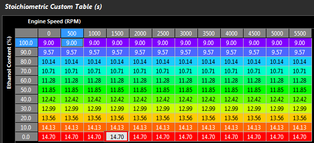
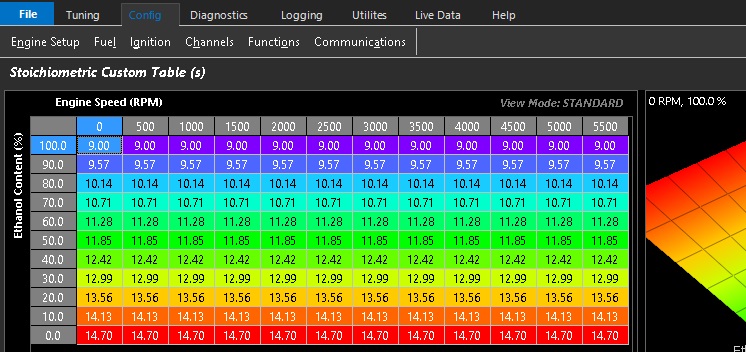
Also, the Stoichiometric Ratio will vary with Fuel Type. A Single Zone if the fuel type is fixed (Figure 2) can be used or a Table allowing the ECU to constantly correct for varying alcohol content. See Figure 3.
Stoich Ratio Setup (single) Figure 2
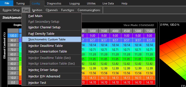
Stoich Ratio Setup (table) Figure 3
Notes on Effective Pusle width
Once the required Fuel Mass has been determined from the calculated Air Mass, the ECU calculates the effective injector pulse width using:
Injector Size
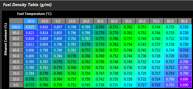
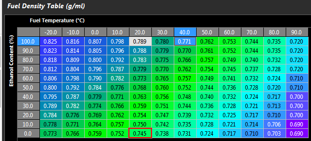
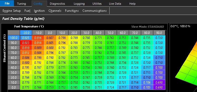
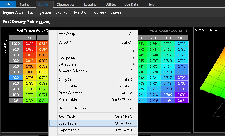
Fuel Density. Fuel density is used to convert between fuel mass and fuel volume and can be a function of both Fuel Temperature and Alcohol Content. A typical Fuel Density table is shown below in Figure 4
Fuel Pressure Correction. Fuel Pressure Correction is based on the injector flow relationship described by Bernoulli’s Equation and allows the effective injector flow rate to be adjusted as the differential pressure across the injector changes.
Note: Fuel Pressure Correction is only applied when enabled using the Config -> Fuel -> Fuel Main → Fuel Pressure Corr. setting.
Fuel Density Table Figure 4
Mass Air Flow Sensor (MAF)
Overview
The Air Flow Sensor(s) provides a measured Air Mass Flow in g/s. The ECU then converts this into air mass per cylinder (g/cyl) giving actual Air Mass into the Engine.
The following MAF input channels can be used:
Mass Air Flow Sensor(s) 1 and 2
Mass Air Flow Bank Sensor(s) 1 and 2 can be used
The ECU will search which channel(s) are enabled and use those inputs. “Mass Air Flow Sensor” takes priority over “Mass Air Flow Bank Sensor”. For example if both
Mass Air Flow Sensor1 and Mass Air Flow Sensor2 input channels are configured the ECU will automatically use both inputs.
MAF systems are more flexible in their ability to compensate for engine changes(like altitude and IAT) since they actually measure airflow instead of calculating it like the Speed Density Fuel Model. It also greatly reduces the tune time as you no longer need to adjust the fueling based on the VE of the Engine… its automatically accounted for by the MAF sensor.
However they also have limitations around restriction and sensor range on high power engines.
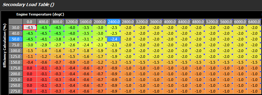
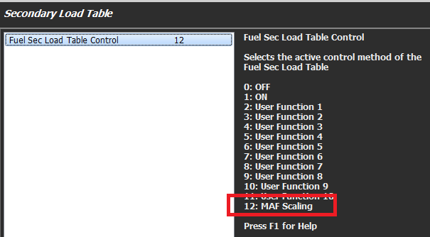
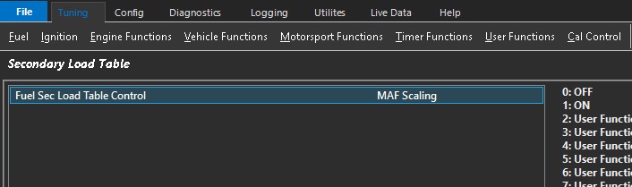
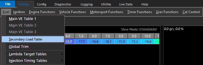
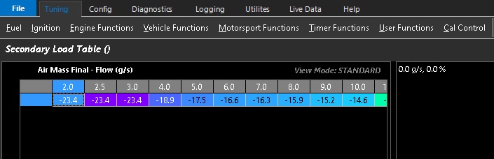
Once the Mass Air has been measured, if the MAF requires further scaling this can be done using a 3D Table. In the real world “small” corrections will need to be applied. This can be done using the Secondary Load Table which will allow a +/- percentage correction to be applied.
A Typical example is shown in below. Table Control should be used to put the Secondary Load Table into this “special” mode shown below
Secondary Load Table used for MAF Sensor
Table Control for Secondary Load Table
Once the Air Mass has been determined, the Stoichiometric Ratio and Lambda Target are used to generate a Fuel Mass (g). The Stoichiometric Ratio will vary with Fuel Type. A Single Zone if the fuel type is fixed can be used or a Table allowing the ECU to constantly correct for varying alcohol content.
Once the Fuel Mass is determined, the Effective Injector Pulse Width can be calculated using:
Injector Size
Fuel Density. Fuel Density can be a function of both Fuel Temperate and Alcohol Content.
Fuel Pressure Correction. The Fuel Pressure Correction is a Fluid Dynamics equation. It allows the injector flow rate to be adjusted as the differential pressure across the injector changes. NOTE: This correction MUST be enabled using the “Fuel Model : Fuel Pressure” setting
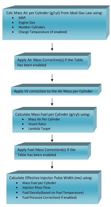
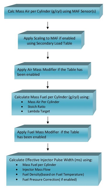
Flow Chart Overview for Mass Air Flow Sensor Fuel Model:
Throttle Mass Flow Setup
Overview
Throttle Mass Flow (TMF) as the name indicates, is the rate at which air mass is flowing through a throttle body in units of grams/second (g/s). Using the throttle body size, throttle area, temperature, pre and post throttle pressures,the ECU can very accurately calculate air flow through the throttle body and therefore into the engine; this is known as the TMF Calculation. Other sensors that also generate air mass flow (g/s) data are Manifold Pressure and MAF sensors. The TMF Calculation is just another method of determining air mass flow and has benefits over MAP and MAF as discussed further down.
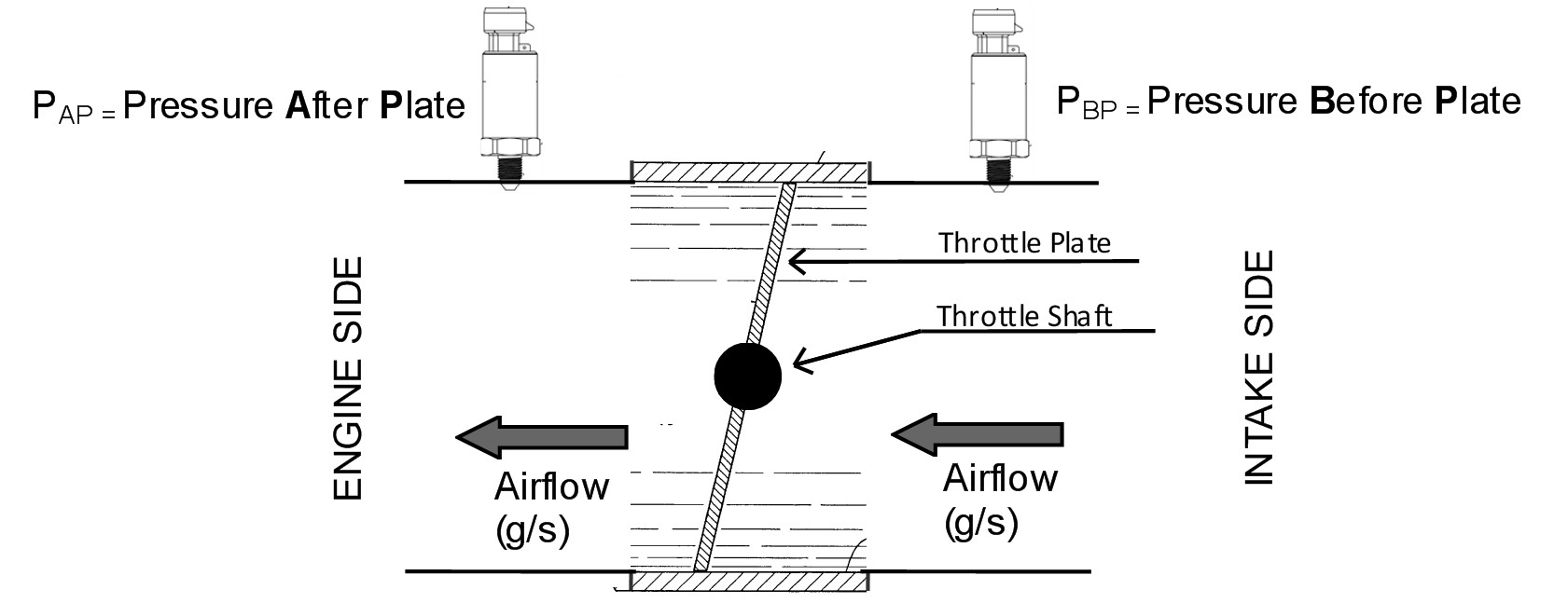
The image below illustrates the basic elements required to calculate TMF.
Getting into more detail, the flow through a throttle body is governed by three physical elements, Conversation of mass, Newtons second law of motion for fluids and Conservation of energy. By combining these elements the ECU can model the flow of fluid through the throttle body accounting for throttle plate thickness and throttle shaft size. By then including real-time data such as the pressure ratio across the throttle plate and the instantaneous throttle area, the ECU can precisely calculate the mass flow rate through a throttle body.
Although these calculation are complex, the TMF setup process for the user is kept as simple as possible with the following inputs and setup required:
Sensor Inputs required
Pressure Before the throttle Plate
Pressure After the throttle Plate
Temperature
Setting required
Throttle Body Size
Throttle Area to Servo Position Correlation Table (Throttle Body Area Table)
The TMF calculation can be summarised by the following equation:
Throttle Mass Flow (g/s) = ( Pafter / Pbefore) x Throttle Area x Modelled throttle body fluid dynamics equation
Settings
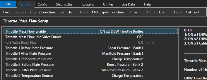
Config-> Air Mass -> Throttle Mass Flow (TMF) Setup
Throttle Mass Flow Enable
Allows the TMF function to be enabled. At this point the ECU is only calculating air mass flow into the engine. Once setup other functions like the Launch and Idle Speed Control can be configured to use the TMF calculated air mass data.
Select which type of throttle system you have:
1x DBW Throttle
2x DBW Throttle
1x Cable Throttle
Throttle Body Size
The Throttle Body inside diameter in millimeters.
Throttle Body Size Scaler
Allows the Throttle Body diameter to be scaled to correct for any system calibration errors. So 60.0 mm diamter with 2.5% scaler gives a throttle diamter of 61.5mm
Default Value = 0.0%
Throttle Mass Flow Filter Mode
This setting controls the Filtering of the Outflow function, a critical part of the TMF Calculation.
Select the Emtron Default to use the Emtron pre-calibrated filter table. Alternativity, for advanced users these default values can be edited using the Custom Table option.
See Tuning -> Air Mass -> Throttle Mass Flow (TMF) User Filter Table
Throttle Mass Idle Valve Enable
Enables the Idle Valve Area to be accounted for in the TMF calculation; the Throttle Body Area AND Idle Valve Area are used to give a Total Area.
Normally only required on a Cable Throttle when an external Idle Air Bleed is used.
Throttle Before Plate Pressure
Pressure source before throttle plate
Commonly Boost Pressure
Also referred to as Charge Pressure
Normally aspirated vehicles can use Barometric Pressure as Pre Throttle pressure source
Throttle After Plate Pressure
Pressure source after throttle plate
Commonly Manifold Pressure
Throttle Temperature Source
The Air temperature input used in the TMF Calculation
Throttle Body Area
Gives the direct relationship between Throttle Area and Servo Position.
See Tuning -> Air Mass -> Throttle Body Model -> Throttle Body Area Table
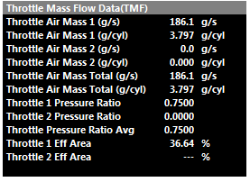
Throttle Mass Flow Runtimes
The following TMF calculated runtimes are generated. See the Runtime menu (F3) Engine Data Calculated tab.
Throttle Air Flow is expressed in units of g/s (grams per second), while Throttle Air Mass is expressed in units of g/cyl (grams per cylinder), representing the mass of air trapped in the cylinder during a single engine cycle.
Throttle Pressure Ratio is the ratio of Pre Throttle Pressure sensing vs Post Throttle pressure sensing (Boost Pressure vs MAP Pressure most commonly)
Throttle Eff Area is the calculated Throttle Area using the Servo Position and the Throttle Body Area lookup table.
All these runtimes can be utilized within other functions.
Functions that can utilize the TMF Calculation
The following functions can use the air mass data generated from the TMF calculation:
Fuel Model
Option 3: Blend - MAP Modelled + Throttle Mass Flow. TMF Fuel Model calculations can offer advantages when the throttle pressure ratio is low (partial throttle) and respond much faster in transient conditions.
For more information see the Fuel Model section.
Idle Speed Control
Option 6: DBW 1 TMF
Option 7: DBW 1+2 TMF
This allows the Idle Speed control to target Mass Flow Rate of g/s. The Throttle Mass Flow (TMF) idle speed control function delivers extremely accurate and rapid idle calculation based on actual engine’s airflow requirements. See TMF Idle Speed Control section for more information
Launch Control
Option 2: Torque Limiting.
The TMF is used to control throttle plate position to achieve a target torque and target launch engine speed.
Tuning TMF
Once TMF is appropriate set up, it can make mapping the engine when it is in use very fast. Using TMF wherever possible is strongly advised by Emtron, especially depending on what kind of dynamometer being used, test conditions, and more – often part throttle and proper transient setup is often forgiven due to time constraints.
Version 1.0
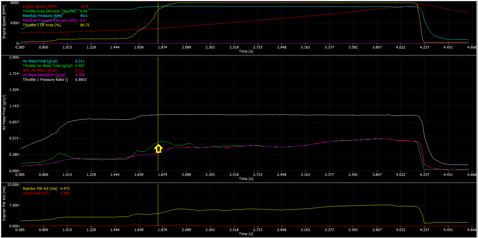
Due to strictly calculating airflow via pressure ratio, the calculation will become invalid at a near equal pressure ratio through the throttle.
Gradually accelerate the engine under load and increase to increase the throttle area demand/effective area.
** Final air mass calculation which can be affected by engine speed (and more) can affect the optimal blend point. This is why most default configurations for the Fuel Model Blend Table include Air Mass Final runtimes.
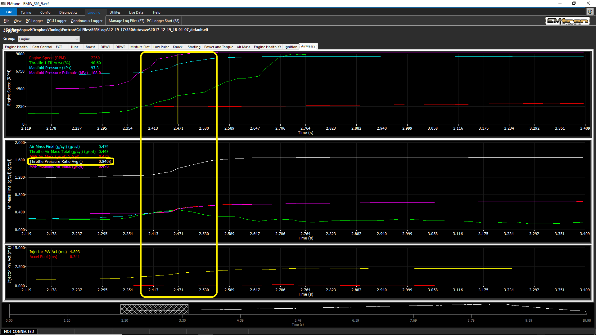
In this particular case the TMF signal at around 0.830 throttle pressure ratio is being unusable.
At this same moment, the Air Mass Modelled/blended calculation is stable and can be blended in.
And/or TMF Out-flowing can generate correct TMF values.
TMF Outflowing calculates TMF airflow when pressure ratio cannot.
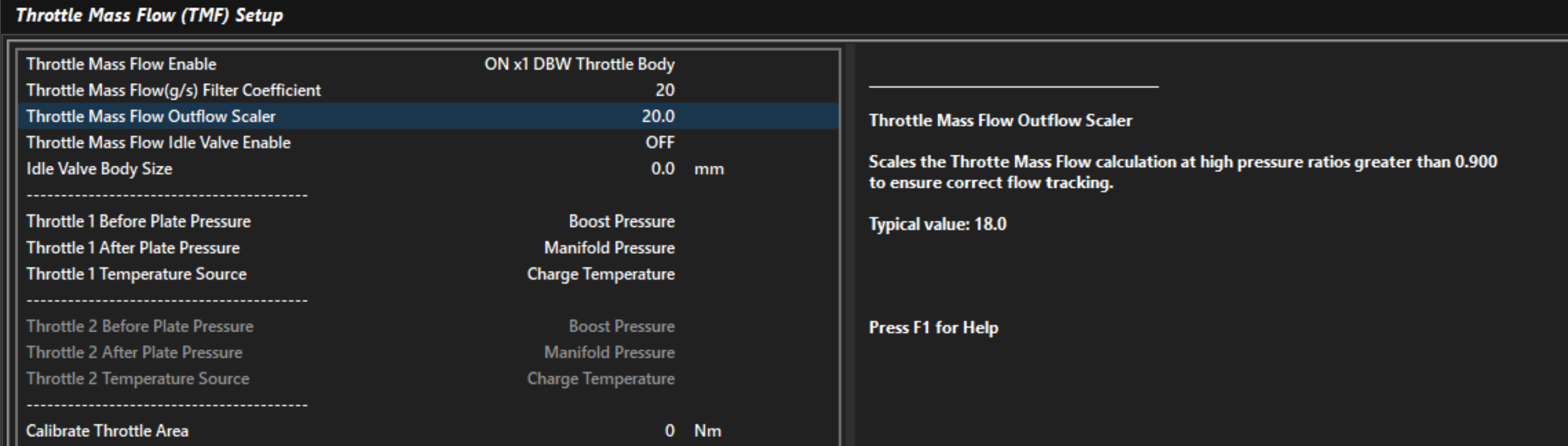
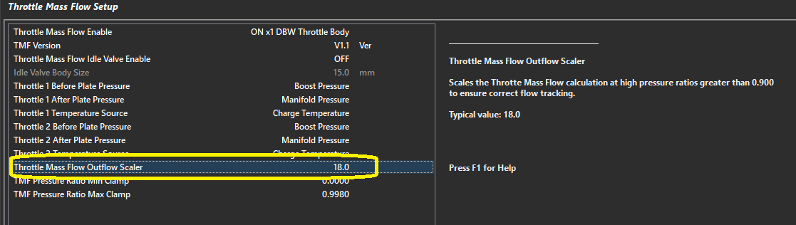
Improper “Outflow Scaler” setting. Adjust Throttle Mass Flow Outflow Scaler to correct
Throttle Mass Flow Air Flow values can only be compared to validated/tuned air flow values (tuned) such as MAP Air Mass or MAF Air Mass.
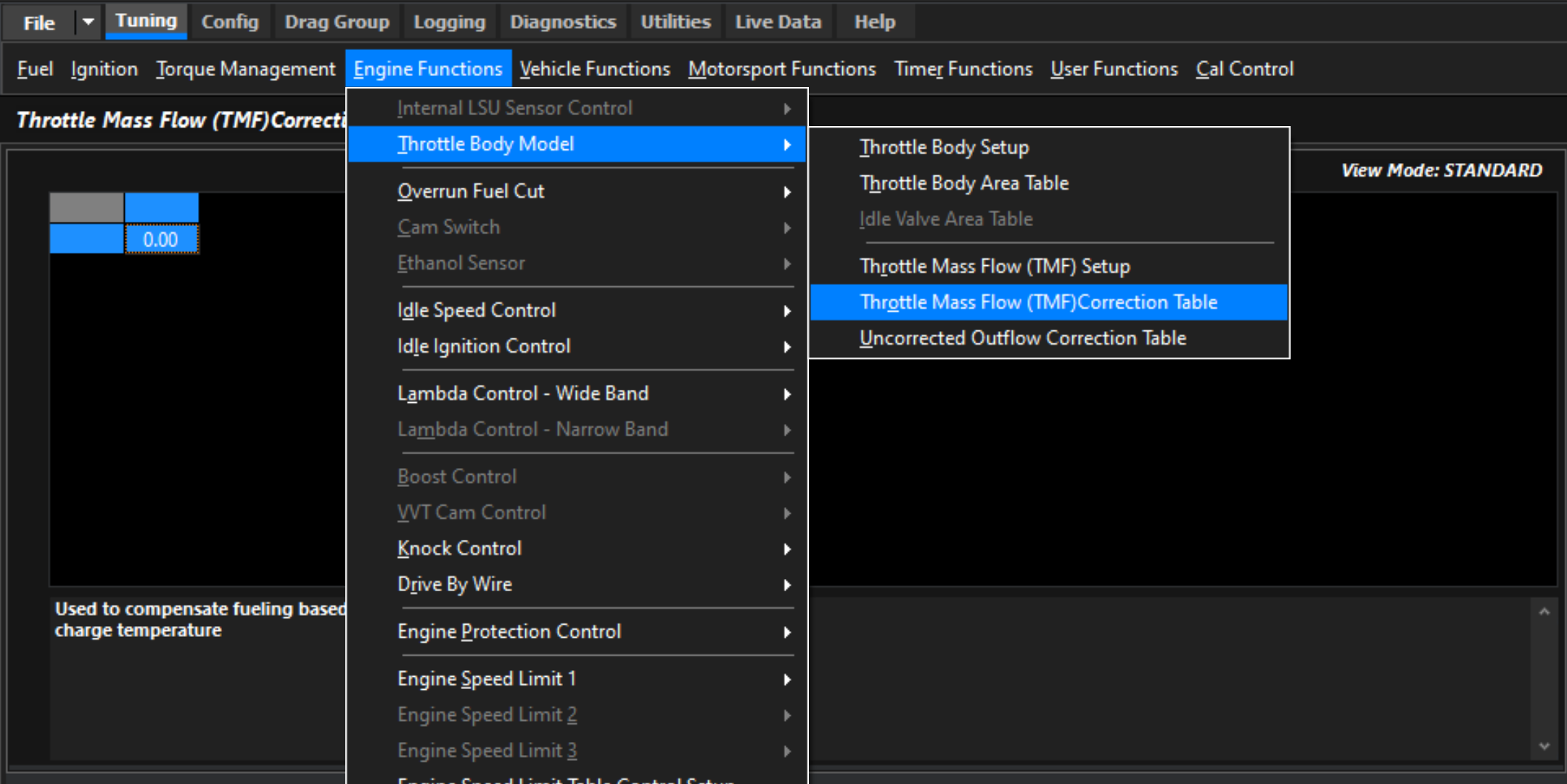
TMF Correction Table
This correction table essentially exists to help remove an error remaining in the system across a wide variety of load & rpm conditions.
Demonstrating error in TMF Calculation that needs to be corrected in TMF Correction Table
Tuning the Throttle Body Area Table
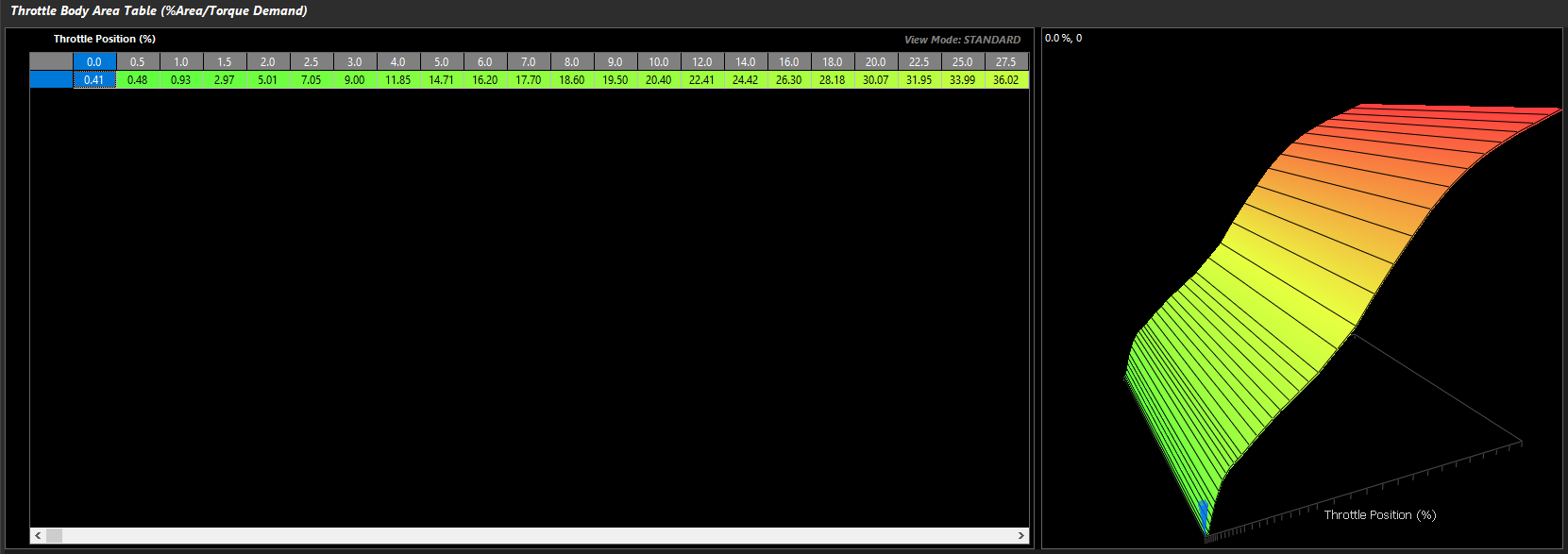
The Throttle Body Area table tells the ECU how much actual throttle area is effective at different throttle positions. This is key to the ECUs further Torque Managing functions, as accurate air mass measurement and actual engine torque go hand in hand.
For torque management, Throttle Area Demand can be manipulated which will be directly proportional to air mass when this is configured correctly
Tuning -> Engine Functions -> Throttle Body Model -> Throttle Body Area Table
This 2D table is all that is needed to appropriately map the given throttle area vs throttle position. As mentioned previously, this allows for extremely fast and accurate mapping of the engine when TMF is active.
It is important to understand that the Pedal Demand and other targeting of throttle area will target the "unit location" in this table, which will then correspond to the DBW Servo Position.
This means, there could be little relationship between Throttle Area Demand and actual DBW Servo Position on fully tuned setups.
Blend tables must be configured completely before tuning
There are multiple ways to calibrate the appropriate throttle area.
Method 1 – Torque verification
With calculated torque channels configured and functional, tuning the Engine Torque (TMF) channels to match the standard Engine Torque channels will allow full mapping of the Throttle Area table. See Torque Management Tuning
Method 2 – Matching other forms of Air Mass measurement
If the application is using a calibrated MAF sensor. Then the throttle area % can be adjusted and matched to TMF air mass VS MAF air mass at different throttle/DBW servo positions.
The same can be done matching TMF air mass VS MAP air mass
MAF/MAP air mass must be validly running the engine - running the commanded lambda target, etc
Method 3 – Matching Lambda
If no MAF sensor is available, setting fuel trims to 0 (or near 0), you can adjust the throttle area to match the target mixture very quickly.
Some extreme applications where live Lambda is unstable may be more difficult to map with Method 3
💡️ Tuning Tip
Per the Matching Lambda validation method, the Throttle Area Table is used to quickly tune the engine operating in TMF by simply manipulating the table at the various throttle areas to match the Lambda Target Table values for that given load. When the correct air fuel ratio is achieved, the Throttle Area Table is essentially validated for the purpose of running the engine. To do this the wideband lambda control should be turned off and the blend bias toward TMF be set to 100%.
Air Mass User 1
Overview
Air Mass User 1 allows the user to create a custom air mass calculation by combining two independent air mass sources. The resulting Air Mass User 1 runtime can then be used throughout the ECU wherever an air mass value is required. A Blend Table is used to determine the contribution of each source to the final air mass value.
This provides a flexible method of constructing advanced air mass calculation strategies that are not possible using the predefined Air Mass Models alone.
The configuration takes place in:
Config -> Air Mass -> Air Mass User 1 Setup. See Air Mass Model Setup
The Blend Table is configured from: Tuning → Air Mass → Air Mass User 1 Blend Table
Air Mass User 1 Setup
The Air Mass User 1 Setup configures the two air mass calculations used to generate the final Air Mass User 1 runtime.
Two independent inputs are available:
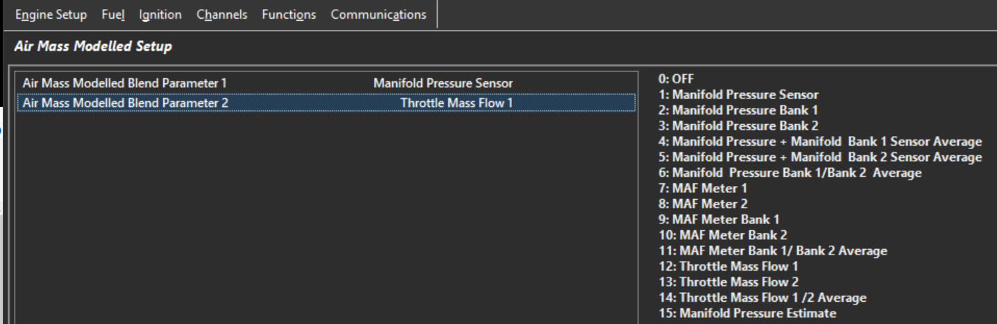
Air Mass User 1 Blend Parameter 1
Air Mass User 1 Blend Parameter 2
Air Mass User 1 Blend Parameters have the following options. Select the two air mass calculations that will be blended together to generate the final Air Mass User 1 runtime:
Value
Blend Parameter
0
Off
1
Manifold Pressure Sensor
2
Manifold Pressure Bank 1
3
Manifold Pressure Bank 2
4
Manifold Pressure + Bank 1 Sensor Average
5
Manifold Pressure + Bank 2 Sensor Average
6
Manifold Pressure Bank 1 / Bank 2 Average
7
MAF Meter 1
8
MAF Meter 2
9
MAF Meter Bank 1
10
MAF Meter Bank 2
11
MAF Meter Bank 1 / Bank 2 Average
12
Throttle Mass Flow 1
13
Throttle Mass Flow 2
14
Throttle Mass Flow 1 / 2 Average
15
Manifold Pressure Estimate
Air Mass User 1 Blend Parameter 1
Select the method of air mass calculation for Parameter 1
Air Mass User 1 Blend Parameter 2
Select the method of air mass calculation for Parameter 2
A common application is blending between Manifold Pressure Sensor and Manifold Pressure Estimate (see further help on MAP Estimate).
If blending is not required, configure both parameters to use the same air mass source or configure the blend table to fully favour the desired calculation method.
Air Mass User 1 Blend Table
The example above shows Speed Density configured as Parameter 1 and Throttle Mass Flow (TMF) configured as Parameter 2.
The Air Mass User 1 Blend Table is a three-dimensional table with configurable axes that determines the blend ratio between the two selected Air Mass User 1 parameters.
0.0% = All Parameter 1
100.0% = All Parameter 2
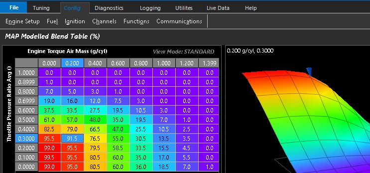
Air Mass Model Blend Table
Overview
The Air Mass Blend Table defines the contribution of two air mass calculations used to generate the final engine air mass value.
The table output is expressed as a percentage and determines the weighting applied to each air mass calculation based on the selected Air Mass Model configuration.
A value of:
0.0% uses 100% of the primary air mass calculation.
100.0% uses 100% of the secondary air mass calculation.
50.0% uses an equal contribution from both calculations.
This allows the ECU to transition smoothly between two air mass calculation methods as engine operating conditions change, combining the advantages of each model over different areas of the engines operating range.
The Air Mass Blend Table is configured from:
Tuning → Fuel → Air Mass Model Blend Table
Air Mass Model 3: Air Mass Modelled + Throttle Mass Flow (TMF) Blend**
0.0% → 100% Air Mass Modelled
100.0% → 100% Throttle Mass Flow (TMF)
Air Mass Model 4: Speed Density (MAP) + Throttle Mass Flow (TMF) Blend**
0.0% → 100% Speed Density (MAP)
100.0% → 100% Throttle Mass Flow (TMF)
Air Mass Model 5: Emtron Air Mass Model
0.0% → 100% Air Mass Model Calculation 1
100.0% → 100% Air Mass Model Calculation 2
The calculation methods used by Calculation 1 and Calculation 2 are configured from the Emtron Air Mass Model setup page.
ℹ️ Important Note: Air Mass Validation*
When an Air Mass Blend mode is enabled, both air mass calculations continue to operate simultaneously regardless of the blend ratio currently being applied.
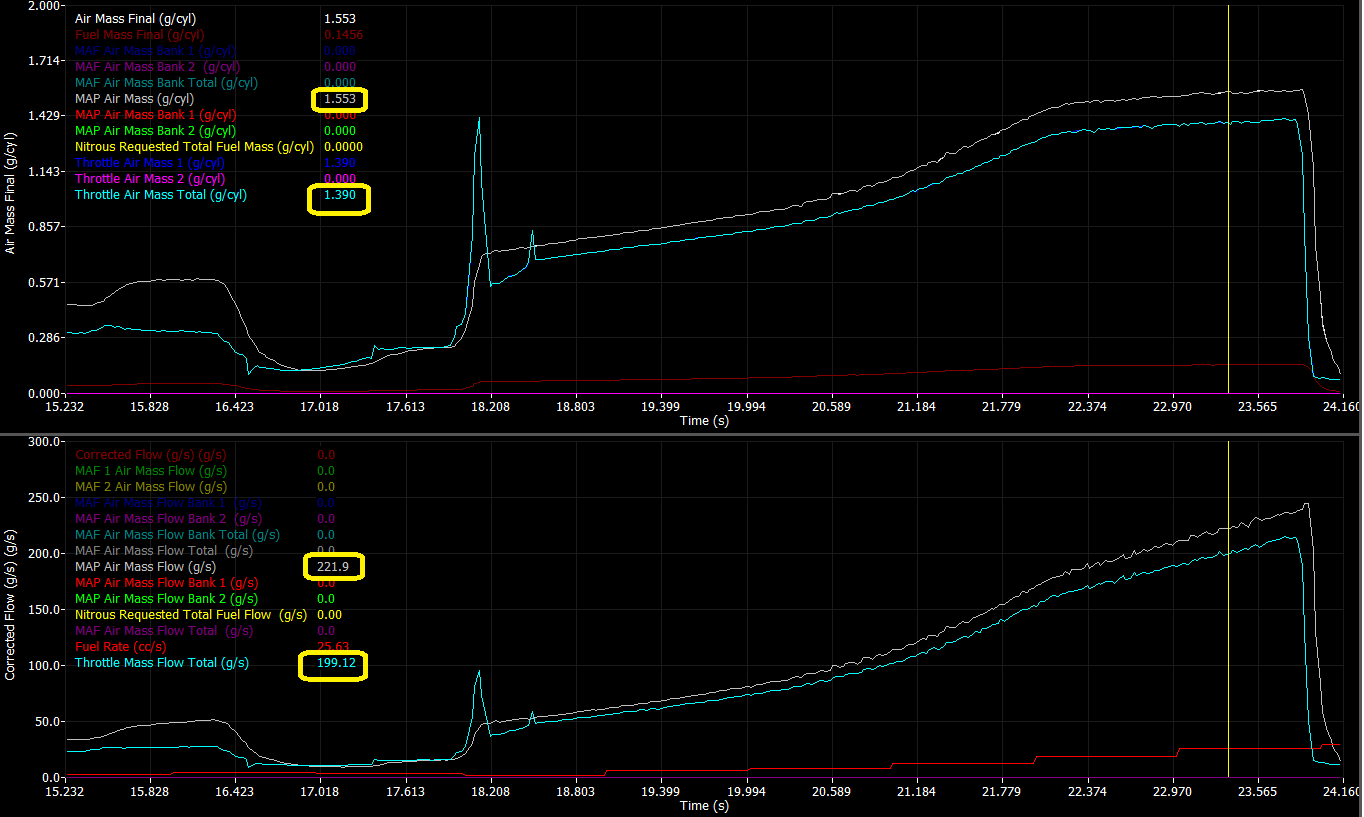
This allows the individual air mass calculations to be logged and compared directly against one another.
If both air mass models have been calibrated correctly, the calculated air mass values should closely overlay one another when operating under the same engine conditions.
For example, when using Speed Density + TMF Blend, the calculated Speed Density Air Mass and TMF Air Mass should produce similar air mass values for a given engine speed and load condition.
Significant differences between the two calculations typically indicate calibration errors within one of the air mass models, such as:
Volumetric Efficiency (VE) calibration errors
TMF model calibration errors
Throttle Body Area table errors
Charge Temperature model errors
Sensor scaling or sensor placement issues
Comparing multiple air mass models in this manner provides a powerful method for validating the engine air mass calibration and improving overall model accuracy.
Below is an example datalog illustrating the correlation between the calculated Speed Density and TMF air mass values under the same operating conditions.
Emtron Air Mass Model
Overview
The Emtron Air Mass Model allows the ECU air mass calculation to be customised using one or two independent air mass calculation methods.
Most applications can be accurately modelled using the predefined Air Mass Models (0 to 4) and no further customisation is required. The Emtron Air Mass Model is intended for advanced applications requiring custom air mass calculations or blending between multiple air mass calculation methods.
Two independent air mass calculations are available:
Air Mass Model Calculation 1
Air Mass Model Calculation 2
Each calculation can be configured to use one of the following air mass calculation methods:
Value
Calculation Method
0
Off
1
Speed Density
2
Mass Air Flow Sensor (MAF)
3
Throttle Mass Flow (TMF)
4
Air Mass Modelled
Single Calculation Mode
If only a single air mass model is required, configure Calculation 1 as required and set Calculation 2 to Off.
In this configuration, the ECU uses the output of Calculation 1 as the final engine air mass value.
Dual Calculation Blend Mode
For applications requiring the advantages of multiple air mass calculation methods, both Calculation 1 and Calculation 2 may be enabled simultaneously.
When both calculations are enabled, the ECU uses the Air Mass Model Blend Table to determine the contribution of each calculation to the final air mass value.
0.0% Blend = 100% Calculation 1
100.0% Blend = 100% Calculation 2
50.0% Blend = Equal contribution from Calculation 1 and Calculation 2
This allows the ECU to transition smoothly between two air mass calculation methods as engine operating conditions change, combining the advantages of each model over different areas of the operating range.
Application Example: Speed Density + Throttle Mass Flow (TMF)
A common application of the Emtron Air Mass Model is blending Speed Density and Throttle Mass Flow (TMF) calculations to take advantage of the strengths of each method.
At low Pressure Ratios (PR) across the throttle body, such as idle, cruise and part-throttle operation, Throttle Mass Flow (TMF) provides superior airflow estimation due to the strong relationship between throttle pressure drop and mass flow.
As the throttle opens and the pressure ratio across the throttle approaches 1.0, the pressure drop across the throttle body becomes very small and the accuracy and sensitivity of TMF reduces. Under these conditions, Speed Density generally provides a more accurate estimation of cylinder air mass.
The Air Mass Model Blend Table can therefore be configured to:
Use predominantly TMF at low pressure ratios.
Progressively transition towards Speed Density as the pressure ratio approaches 1.0.
Operate using predominantly Speed Density during high load and wide open throttle operation.
This approach combines the excellent transient response characteristics of TMF with the steady-state accuracy of Speed Density.
At throttle pressure ratios above approximately 0.9 (Post-Throttle Pressure / Pre-Throttle Pressure), the pressure differential across the throttle body becomes very small, reducing the resolution of the Throttle Mass Flow (TMF) calculation. This is why TMF must always be blended with an alternative air mass calculation method and cannot be used as the sole air mass model for engine operation.
The Air Mass Blend Table should therefore progressively transition from TMF to an alternative air mass calculation method as the throttle pressure ratio approaches 1.0.
The Air Mass Blend Table forms part of the engine air mass model and must be finalised before tuning starts.
The TMF Correction Table can be used to make small adjustments to the TMF calculation if required. In most applications, little or no correction should be necessary.
Air Mass Bank Control
Air Mass Bank Control allows the ECU to independently calculate the engine air mass for each cylinder bank. This option is only available using the Emtron Air Mass Model.
When enabled, each bank operates as an independent air mass model and requires the appropriate sensors and inputs to support bank-specific airflow calculations.
Typical examples include:
Independent inlet manifolds.
Dual throttle body systems.
Dual plenum engines.
Engines equipped with bank specific pressure, temperature or airflow sensors.
Additional Information: Bank Control
1) Engines with inlet manifolds connected by a balance tube or crossover passage may not exhibit true banked airflow behaviour. Any pressure differential between the manifolds will result in airflow transfer through the balance passage, reducing the effectiveness and accuracy of independent bank air mass calculations.
2) Air Mass Bank Control is available for all Air Mass Model types.
2) Ensure the Bank Cylinder Setup table is configured correctly before enabling Bank Mode.
3) Air Mass Bank Control is not compatible with Staged Injection operation.
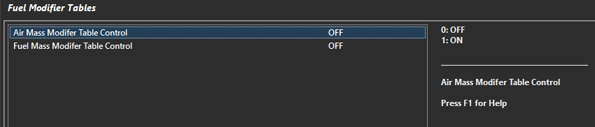
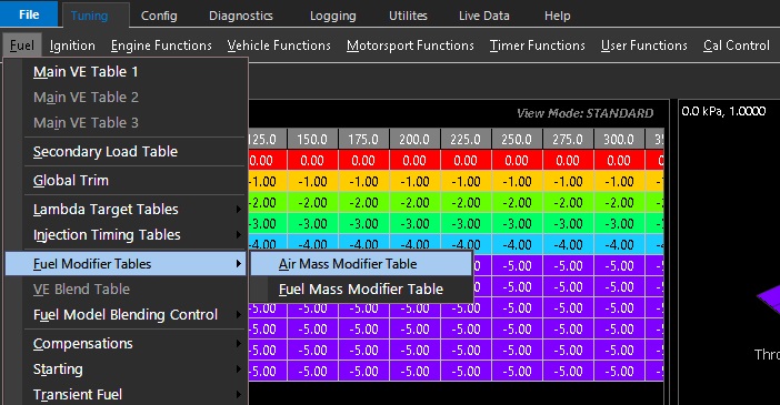
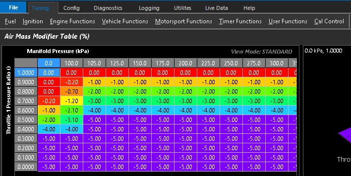
The Air Mass Modifier Table is enabled via Tuning -> Fuel Table Control -> Fuel Modifier Tables
Values in this table modify the ECUs Final Air Mass directly as a percentage
Bank Mass Air Flow Sensor
The ECU Independently controls the Fueling for the Engines Banks 1 and 2 using either two MAF Sensors . Required when there
is no common plenum between the cylinders banks.
Make sure the “Bank Cylinder Setup” Table is correctly initialised.
The Input “Mass Air Flow Meter 1” is used to control the Fueling on Bank 1.
The Input “Mass Air Flow Meter 2” is used to control the Fueling on Bank 2
Banked Speed Density
The ECU Independently controls the Fueling for the Engines Banks 1 and 2 using two MAP Sensors . Required when there is no common plenum between the cylinders banks.
Make sure the “Bank Cylinder Setup” Table is correctly initialised.
The Input channel “Manifold Pressure - Bank 1” is used to control the Fueling on Bank 1.
The Input channe; “Manifold Pressure - Bank 2” is used to control the Fueling on Bank 2.
Exhaust Pressure Estimate
For use when no Exhaust Pressure sensor is available.
Exhaust Pressure Estimate Setup
0: OFF
1: ON
Exhaust Pressure Estimate Table
3D table that with configurable axis to tune the Exhaust Pressure Estimate.
Units = kPa
Manifold Pressure Estimate
Generates a Manifold Pressure Estimate using a % Scaling table on the selected parameter.
Manifold Pressure Estimate Setup
0: OFF
Function is off
1: Table Value
Manifold Pressure Estimate Table = Raw Value
Table value = 50.8%
Manifold Pressure Estimate = 50.8 kPa (1:1)
2: % Barometric Pressure
Table value = 50.8%
Barometric Pressure = 96.8kPa
Manifold Pressure Estimate = 96.8kPa x 50.8% = 49.1kPa
3: % Manifold Pressure
Table value = 50.8%
Manifold Pressure = 96.8kPa
Manifold Pressure Estimate = 96.8kPa x 50.8% = 49.1kPa
4: % Manifold Pressure Bank 1/2 Average
Table value = 50.8%
Manifold Pressure Bank 1/2 Average = 96.8kPa
Manifold Pressure Estimate = 96.8kPa x 50.8% = 49.1kPa
5: % Boost Pressure
Table value = 50.8%
Boost Pressure = 253.6kPa
Manifold Pressure Estimate = 253.6kPa x 50.8% = 128.8kPa
6: % Boost Pressure Bank 1/2 Average
Table value = 50.8%
Boost Pressure Bank 1/2 Average = 253.6kPa
Manifold Pressure Estimate = 253.6kPa x 50.8% = 128.8kPa
Manifold Pressure Estimate Table
3D table that with configurable axis to tune the Manifold Pressure Estimate
Units = % and correspond to Manifold Pressure Estimate Setup parameter
Mass Air Flow Sensor (MAF) + AirMass Modelled (Blend)
A Blend Table generates a Final Air Mass using a ratio from the MAF Sensor and Air Mass Modelled.
The following MAF input channels can be used:
Mass Air Flow Sensor(s) 1 and 2
Mass Air Flow Bank Sensor(s) 1 and 2 can be used
The ECU will search which channel(s) are enabled and use those inputs. “Mass Air Flow Sensor” takes priority over “Mass Air Flow Bank Sensor”. For example if both
Mass Air Flow Sensor1 and Mass Air Flow Sensor2 input channels are configured the ECU will automatically use both inputs.
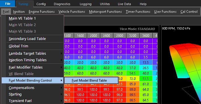
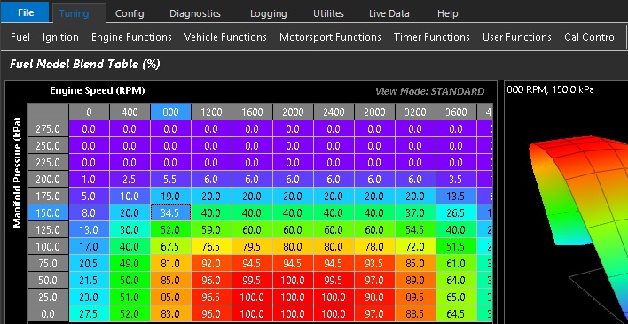
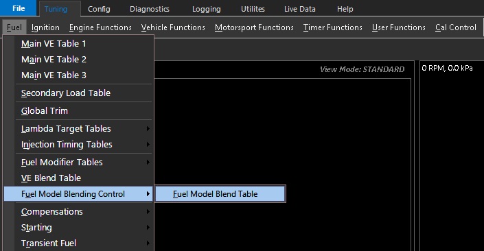
The fuel model blending control table is accessed from : Tuning -> Fuel -> Fuel Model Blending Control
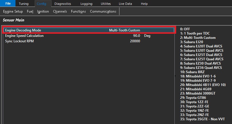
The Engine Decoding Mode selects the trigger pattern and decoding used by the ECU to determine engine position and synchronisation.
The selected mode determines how the ECU interprets the crankshaft and camshaft trigger signals, establishing the engine position used by the ECU for ignition timing, fuel injection timing and other engine position-dependent functions including Variable Valve Timing (VVT), knock control and torque control etc.
For predefined decoding modes (Option 3 and above), the ECU will initialize both the Crank Index and Sync Sensor channels to the correct settings. This includes:
Sensor Type
Sensor Edge
Sensor Pull-up
Arming Threshold Tables
This is considered Pre-Defined Decoding. All settings for Tooth Count, Index Tooth and Crank Index Offset are controlled by the ECU firmware and cannot be customized. However, the Edge Type, Pull-up, and Arming thresholds can all be adjusted after the new decoding mode has been selected.
The most common adjustment is configuring the Arming Threshold Tables when using magnetic (VR) sensors. As a general guideline, the arming thresholds should initially be set to approximately 60% of the peak sensor voltage.
Use the Emtron Scope function to measure the peak crankshaft and camshaft sensor signal voltages to configure the Arming Threshold Tables correctly. See here for more information: Setting Arming Threshols
The predefined decoder modes are intended for engines using the standard OEM trigger pattern. If your engine uses a modified or custom trigger arrangement based on one of these engines, select Multi-Tooth Custom where appropriate or contact Emtron Support for assistance configuring the trigger system.
Any setting change in the Crank Index or Sync Sensor menu that differ from the default values may cause permanent engine damage.
Modifying the automatically configured Crank Index or Sync Sensor settings for a predefined decoder may result in incorrect engine synchronisation and ignition timing. Incorrect Engine decoding configuration can prevent the engine from starting or, in severe cases, may result in engine damage.
–
Engine Speed Calculation
This setting defines the number of crankshaft degrees over which engine speed is calculated. A wider measurement window provides greater averaging and a more stable engine speed calculation.
Typical values range from 1 TDC event (90° for an 8-cylinder engine, 180° for a 4-cylinder engine) up to 1/2 of an engine cycle (360°).
The maximum value is 2 engine cycles (1440°)
Sync Lockout RPM
The Sync Sensor input is ignored when engine speed is above this value.
This setting is primarily used to help diagnose engine decoding errors occurring at high engine speeds. For example, if an engine decoding error occurs at 6500 RPM, setting Sync Lockout RPM to 6000 RPM will cause the ECU to ignore the Sync Sensor above 6000 RPM.
If the decoding error no longer occurs, this indicates that the Sync Sensor or its associated signal may be the cause of the issue.
Setting this value to 20,000 RPM disables the Sync Lockout feature.
Arming Thresholds
Overview
The Arming Threshold defines the voltage level that the input signal must cross before the input circuit considers the signal valid. This applies regardless of signal type, including magnetic (VR) and digital inputs.
Magnetic (VR) Sensors
The Arming Threshold defines the voltage level that the input signal must exceed before the input circuit is armed and ready to detect a trigger event. Once armed, the input circuit waits for the signal to transition through the zero-crossing point from a positive voltage to a negative voltage.
NOTE: The Arming Threshold does not define the actual trigger point in this mode. It only determines when the input circuit is armed and ready to detect the subsequent zero-crossing event.
Hall Effect/ Digital Sensors
The Arming Threshold defines the voltage level that the input signal must cross before the trigger circuit is armed and ready to detect the selected trigger edge. Once the arming condition has been met, the trigger event occurs when the signal transitions through the configured Sensor Edge (rising or falling edge).
The correct Arming Threshold configuration ensures reliable trigger detection across the full engine operating range and helps prevent trigger errors, excessive error counts, misfires, or no-start conditions.
Additional Information
For Magnetic (VR) sensors, the required Arming Threshold typically increases with engine speed as the generated signal voltage increases. For this reason, the Arming Threshold should be configured using a table that increases with RPM to maintain reliable trigger detection across the full engine operating range. In most applications, the maximum Arming Threshold required for stable operation is typically no more than 8 V.
For Magnetic (VR) sensors, the required Arming Threshold naturally increases with engine speed as the sensor output voltage increases. This is a desirable characteristic, as the higher threshold also improves noise immunity by rejecting low-amplitude electrical interference while maintaining reliable trigger detection.
For Hall effect and other digital sensors, the signal voltage is normally independent of engine speed. As a result, the Arming Threshold typically remains constant across the full engine operating range.
The maximum configurable Arming Threshold is 12V.
The Emtron trigger inputs are designed to withstand signal amplitudes of up to ±100V.
Arming Threshold Setup
The Emtron Scope function should be used to setup the Arming Threshold Tables by measuring the peak sensor voltage across the engine operating range.
Magnetic (VR) Sensor Arming Threshold Setup
Configure the Arming Threshold to approximately 50% of the measured peak sensor voltage at each engine speed. This positions the threshold above ground noise while allowing sufficient margin for normal signal amplitude variation, improving trigger reliability.
In most applications, the maximum Arming Threshold required for reliable operation is approximately 8 V. If the peak sensor voltage exceeds 16 V, an Arming Threshold of 8 V is generally suitable.
Digital Sensor Arming Threshold Setup
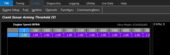
For digital 0–5 V square-wave signals, configure the Arming Threshold to a fixed value of approximately 2.0 V across the entire engine operating range. This provides a stable switching point while maintaining adequate noise margin between the low and high signal levels.
Example:
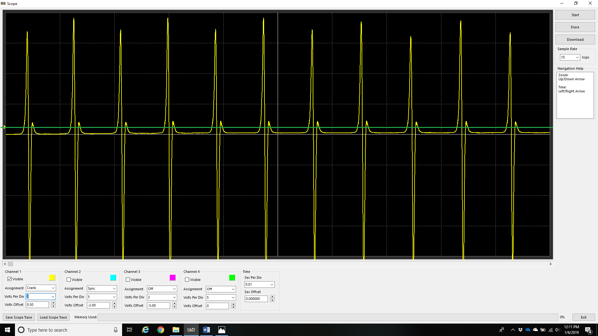
The following example uses the Emtron Scope function to view the crankshaft sensor signal and identify a trigger signal integrity issue. The measured signal amplitude is then used to re-configure the Arming Threshold, resulting in reliable trigger detection.
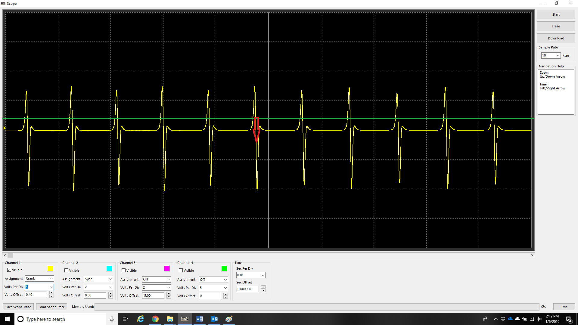
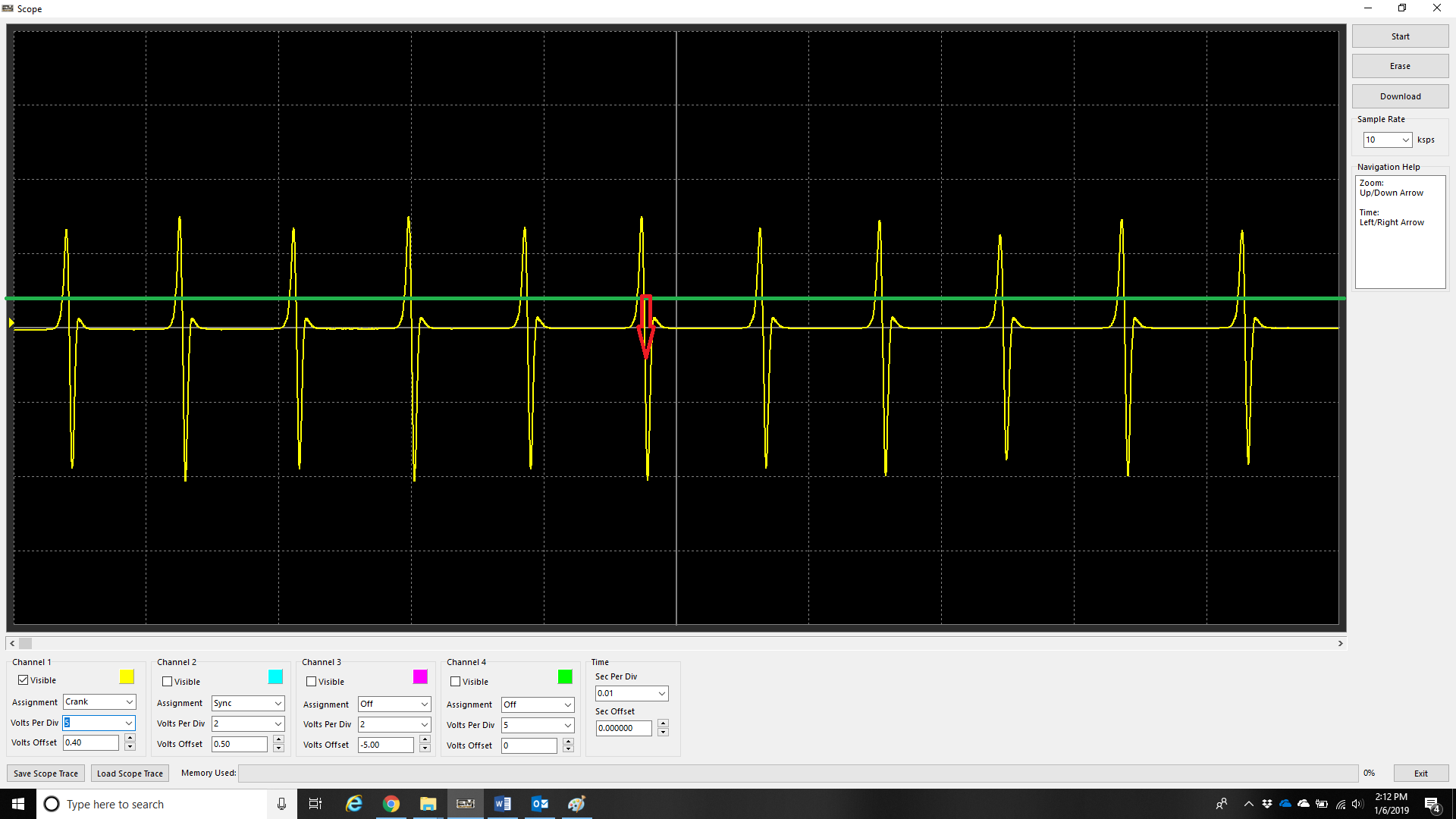
The above example shows a crankshaft trigger signal with the Crank Sensor Arming Threshold set too low (0.5 V), represented by the green line.
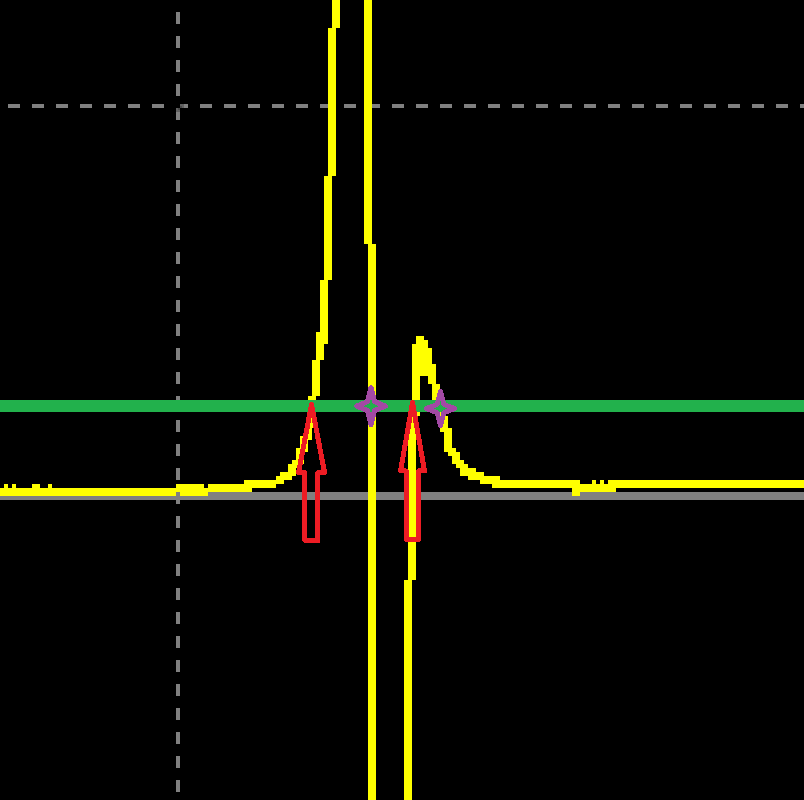
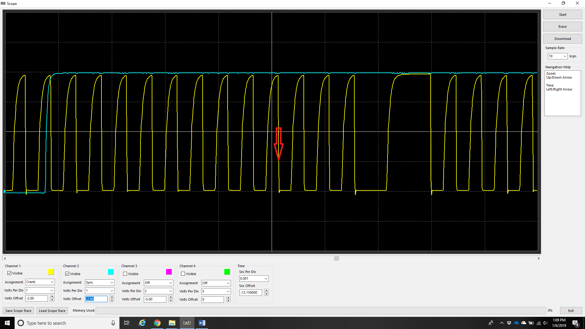
With the above example zoomed in, the trigger signal can be seen crossing the Arming Threshold (green line) twice, indicated by the red arrows. Each time the signal subsequently transitions through the zero-crossing point, the ECU detects a trigger event (purple markers). The first trigger event is the valid tooth, while the second is a false trigger caused by the Arming Threshold being set too low.
Increasing the Arming Threshold above the secondary signal oscillation prevents the input circuit from re-arming, eliminating the false trigger. In this example, increasing the Arming Threshold to approximately 3.0 V resolves the issue.
Crank Index Offset Setup
Overview
The Crank Index Offset Setup is one of the most critical configuration steps within the ECU.
The ECU determines engine position by detecting a known trigger event, commonly referred to as the Index Tooth. Since the Index Tooth position does not normally coincide with Top Dead Centre (TDC) Cylinder #1 Compression, the Crank Index Offset defines the angular relationship between these two events. This allows the ECU to accurately determine crankshaft position and maintain synchronisation with the engine.
Tuning Tips:
1) For Wasted Spark applications, always set the Ignition Lock Angle to 0.0° BTDC when verifying the Crank Index Offset.
Many timing lights calculate ignition advance using the measured ignition pulse frequency. Since wasted spark systems generate two ignition events per engine cycle, some timing lights may calculate an incorrect engine speed and display an incorrect ignition advance value. Using a lock angle of 0.0° BTDC allows the crankshaft TDC mark to be verified directly and eliminates this source of error.*
2) For Direct Fire ignition systems, the Ignition Lock Angle may be set to any convenient crankshaft timing mark available on the engine pulley.
3) The fuel injectors can be disabled to validate the initial Crank Index Offset value.prior to starting the engine. See Config -> Fuel -> Fuel Main -> Injection Mode -> Off.
4) Direct fire engines may be 360deg out of cycle which can be corrected numerically (i.e add or subtract 360 from the Crank Index value).
Ignition Timing Synchronisation
Before calibrating the ignition system, the ECU ignition timing must be synchronised with the actual engine crankshaft position.
Crank Index Offset Calibration
Enable Ignition Lock and configure a fixed ignition timing value using the Ignition Lock Angle. NOTE: When Ignition Lock Enable is ON, Ignition Lock Angle value overrides all other timing values in ECU.
Start the engine and use a timing light to measure the actual ignition timing.
Compare the measured ignition timing with the configured Ignition Lock Angle.
Adjust the Crank Index Offset until the timing light reading matches the configured Ignition Lock Angle.
This procedure should be performed with the engine operating at idle speed.
Ignition Delay Time Calibration
Once the Crank Index Offset has been calibrated at idle, ignition timing should be verified over the engine operating range.
As engine speed increases, ignition coil turn-on delays, ignition module propagation delays and ECU output delays can introduce small timing errors.
The Ignition Delay Time parameter compensates for these delays to ensure the commanded ignition timing accurately matches the actual crankshaft position across the complete engine speed range.
Adjustment guidelines:
If the measured ignition timing retards as engine speed increases, increase the Ignition Delay Time value.
If the measured ignition timing advances as engine speed increases, decrease the Ignition Delay Time value.
Once correctly calibrated, the timing light should indicate a constant ignition timing value regardless of engine speed when Ignition Lock is enabled.
Important:
The Crank Index Offset and Ignition Delay Time should always be verified regardless of trigger presets or predefined trigger configurations.
Incorrect calibration will result in the ECU commanding ignition timing that does not match the actual crankshaft position, potentially causing poor engine performance or engine damage.
Crank Index and Sync Sensor
Overview
The Crank Index Sensor establishes the crankshaft position, while the Sync Sensor identifies the engine phase within the complete engine cycle. This allows the ECU to determine the exact engine position and correctly identify the individual cylinder events.
For example, a conventional four-stroke engine has a 720° engine cycle, while a rotary engine has a 360° engine cycle.
The sensor type, signal edge, and pull-up configurations can be set from this menu.
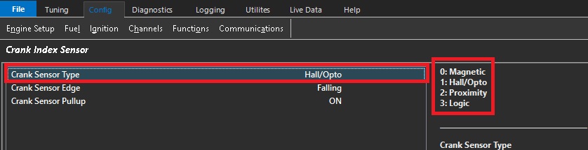
Sensor Type
The Sensor Type setting defines the type of sensor connected to the selected Crank Index Sensor or Sync Sensor input.
Value
Sensor Type
0
Magnetic
1
Hall Effect or Optical
2
Proximity
3
Logic (available in a future release)
Magnetic
Magnetic sensors are voltage-generating sensors that produce a sinusoidal signal. The signal swings both positive and negative around 0V, with the signal amplitude generally increasing as engine speed increases. Magnetic sensors can typically be identified by having two signal wires.
Warning
Always use the dedicated positive and negative trigger inputs on the ECU for the Crank and Sync sensors. Do not connect the sensor ground to the engine block or chassis. The sensor(s) must be wired directly to the dedicated ECU trigger inputs.
Magnetic sensors must use shielded cable from the sensor through to the ECU input. Magnetic sensor signals are particularly susceptible to electrical interference, especially from radiated interference generated by the ignition system. Sensor wiring must be routed well away from ignition coils, ignition wiring, and other sources of electrical interference. The cable shield must be connected to the ECU Shield connection, correct wiring practices are therefore essential.
Magnetic sensor polarity must be correct. Incorrect polarity can result in poor or unstable engine decoding. See Using the Scope – Incorrect Crank/Sync Sensor Polarity for further information.
Hall Effect / Optical
Hall Effect and optical sensors produce a digital square-wave signal and require a power supply to operate. They can typically be identified by having three wires: supply, signal, and ground.
Emtron ECUs provide a dedicated 8V sensor supply to provide a regulated and clean power supply for these sensors.
Warning
Always use the dedicated positive and negative trigger inputs on the ECU for the Crank and Sync sensors. DO NOT connect the sensor negative or ground to the engine block or chassis.** DO NOT connect Hall Effect ground (or any other “Pulsed” sensor grounds) to Analog Volt Ground pins. The sensor(s) must be wired directly to the dedicated ECU trigger inputs.
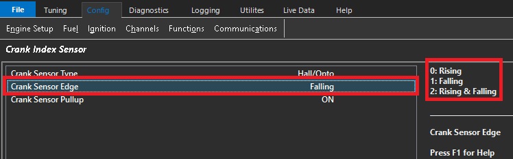
Sensor Edge
This setting defines which edge of the Crank Index or Sync Position sensor signal is used by the ECU for engine position and synchronisation.
Value
Edge
0
Rising
1
Falling
2
Rising & Falling
Sync Sensor Rising and Falling
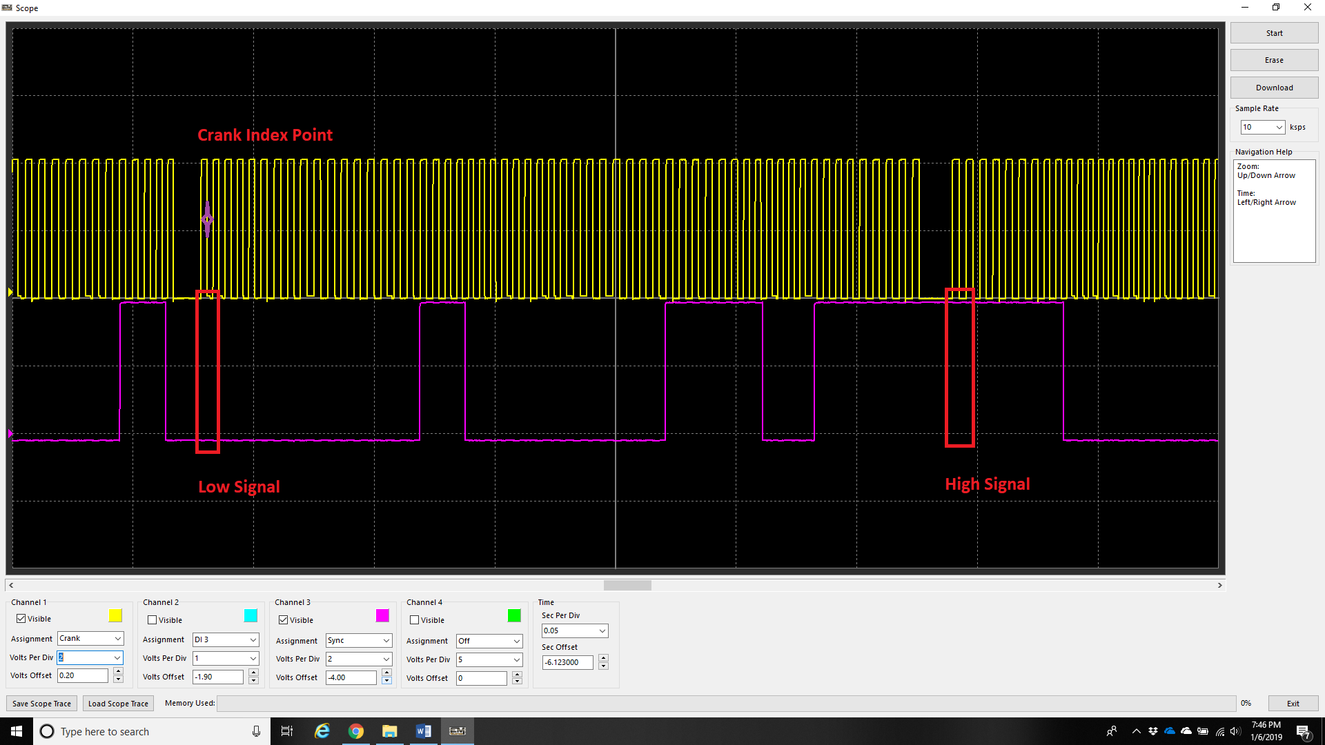
Engines with multi-tooth sync sensors will typically have a “long” tooth at the crank index point.
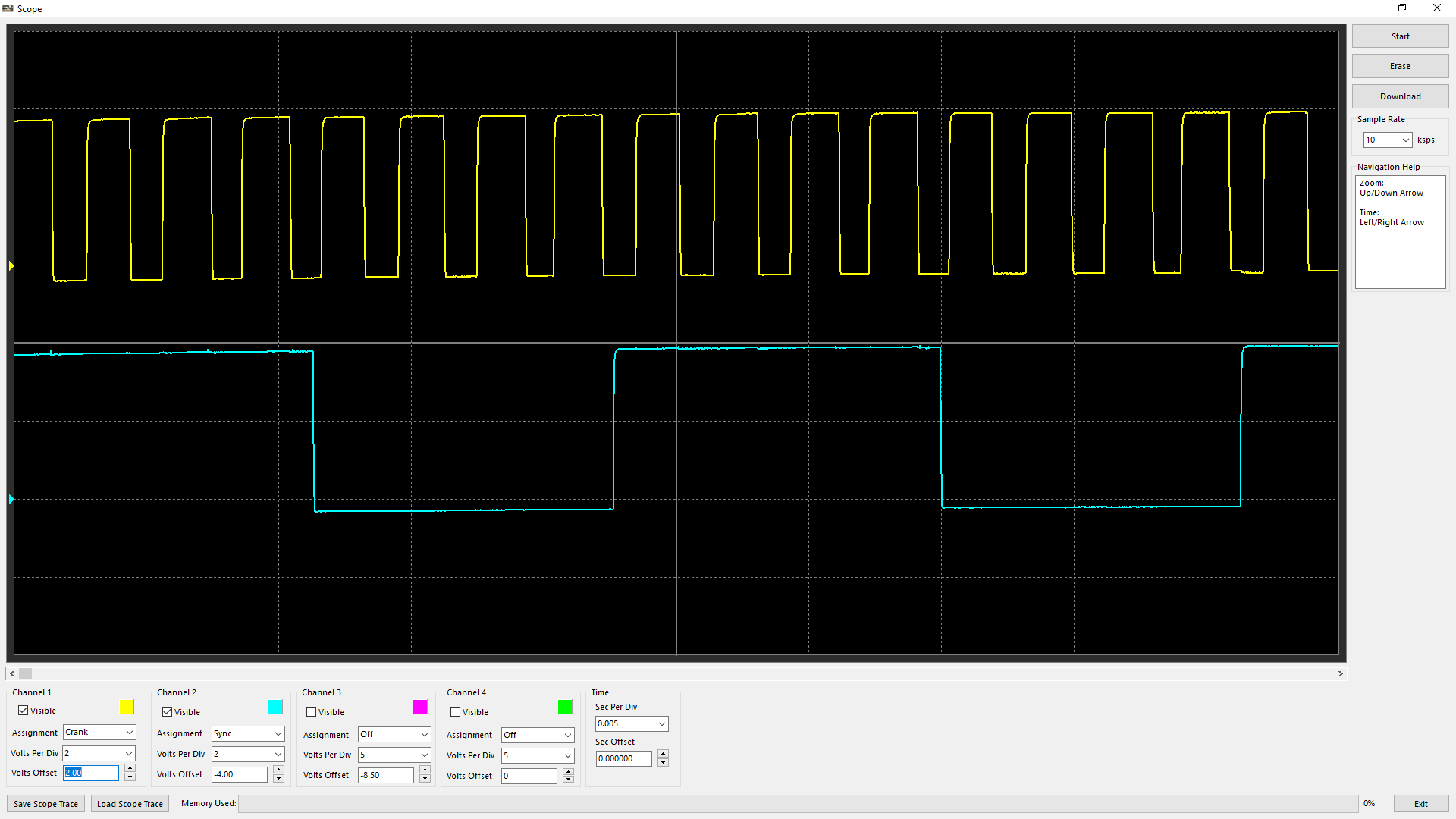
In this configuration, the Sync Sensor provides a different signal level for each half of the engine cycle:
For example in the above image:
0–360°: Sync signal is Low (Purple trace)
360–720°: Sync signal is High (Purple trace)
The ECU uses the Crank Index gap to establish the crankshaft position and the Sync signal level to immediately determine which 360° half of the engine cycle the crankshaft is in.
This means the ECU does not need to wait for an additional Sync edge to determine the engine position. As soon as the first crank index gap is detected, the ECU can determine the 720° engine position from the combination of the crank index position and the current Sync signal level.
For these trigger types, set the Sync Sensor Edge configuration to Rising and Falling.
Additional Information
For further information on multi-tooth sync sensors, Rising and Falling Edge configuration, or trigger decoding, contact Emtron Technical Support.
Custom Engine Decoding Modes
When using a custom decoding mode, such as 1 Tooth per TDC or Multi-Tooth Custom, Falling Edge should be used unless otherwise instructed by Emtron Support.
: Edge Selection Notes
Magnetic Sensors have the edge selection locked to Falling Edge. The ECU detects the positive to negative transition of the sensor signal and determines the trigger position from the zero-crossing point.
For Hall Effect Sensors, the Falling Edge is generally preferred as it provides the sharpest and most consistent signal transition. A faster signal transition allows the ECU to determine the engine position more accurately and reduces timing variation caused by slow or noisy signal transitions. This is particularly important for the Crank Index Sensor, where accurate and repeatable trigger position is critical.
For a Sync Position Sensor, the sensor is not normally used to determine the primary crankshaft position, so the exact edge transition and its slope are less critical. For this reason, the Rising Edge may also be used if required. For example, if the selected sync edge is too close to a crank decoding edge, the opposite edge can be selected to move the sync event further away from the crank decoding event and provide a more reliable sync position.
The example above illustrates the fast Falling Edge of a magnetic sensor signal
The example above illustrates the fast Falling Edge of a Hall Effect sensor signal.
Triggering from the Rising Edge in either of the two examples above will cause the engine timing to wander as RPM changes.
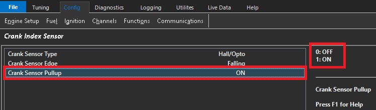
Sensor Pullup
This setting controls the internal 5V pull-up used with Hall Effect, Optical, and Proximity Crank Sensors.
The pull-up is not available when using a Magnetic sensor.
Value
Pull-Up
0
OFF
1
ON
Sensor Arming Threshold
Arming thresholds for digital signals (including crank and sync sensors) describe the level in which the voltage level must go above before the signal can be valid. Regardless of signal (magnetic, or digital), the threshold voltage level must be reached before the signal can be considered valid.
** The threshold value does not mean this is the value in which the ECU “triggers”.
Typical Arming Threshold values for a Magnetic Sensor are shown in the image above. Note how the Arming Threshold increases as engine speed increases.
Typical Arming Threshold values for a Hall Effect Sensor are shown in the image above. For a standard 0–5V square-wave signal, it is recommended to set the Arming Threshold to a constant 2.0V across the entire table. This is approximately 40% of the sensor pull-up supply voltage.
Additional Information:
Arming Threshold control is available for all trigger types.
Use the Scope function within the Emtron to validate the voltage threshold to be used.
Pre-Defined Engine Decoding Modes
When using a Pre-Defined Engine Decoding Mode (3 or higher), the Crank/Sync Sensor Type, Edge Configuration, and Pull-Up Configuration are pre-configured for the selected decoding mode. These settings should not normally be changed.
Multi Tooth Setup
Multi Tooth Setup
This allows the user to define a Custom decoding mode for the ECU to use. In order for the ECU to synchronize timing of the engine, an “index tooth” position must be identified. :
The following settings are configured in this menu item :
When using a Custom Decoding mode, it is important to understand how and where the “index tooth” is identified, especially if the engine has adjustable triggers (mechanically).
On Non-Missing tooth Crank Triggers, there must be a sync sensor so the ECU can identify the “Index Tooth”
The Sync Sensor must be Camshaft driven if sequential fuel injection/direct fire ignition modes are being used
Missing Tooth Triggers do not require a sync sensor to identify the “Index Tooth”
An example of a 4 Tooth Crank Wheel with a single tooth (50/50) Sync Sensor driven off a Camshaft (both Hall sensors)
Also known as 1-Tooth per TDC
** Note - This trigger could also be an example of a Crank Trigger being driven off of a Distributor (8 teeth), and therefore Camshaft driven
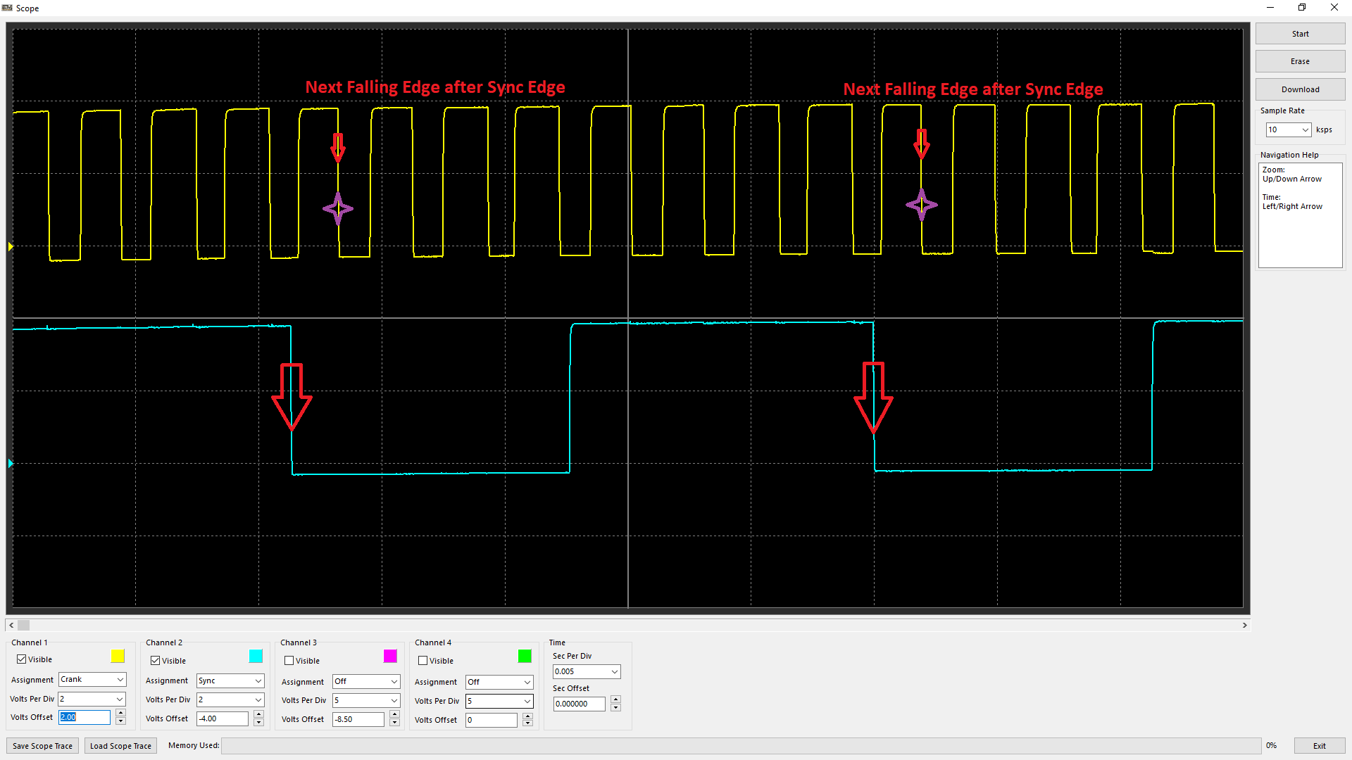
In this case, Edge configuration being set to both Falling Edge (see Crank Index/Sync Sensor Setup), the “Index Tooth” is identified as above
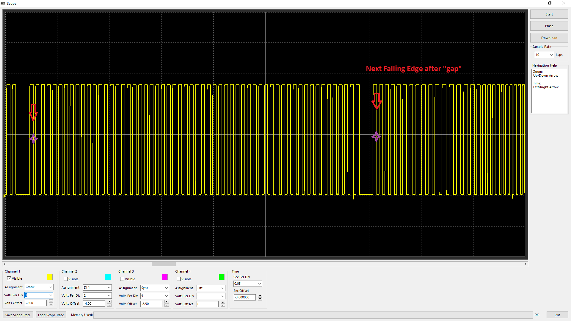
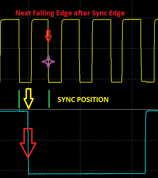
With a Missing Tooth crank trigger, the “Index Tooth” is recognized by the next Falling Edge after the gap position.
** Note - no Sync Sensor is even shown
** When using Magnetic Triggers, with incorrect polarity the ECU will not be able to recognize the gap and/or the “Index Tooth” position correctly. See Scope - Uses of Scope - Improper Crank/Sync Sensor Polarity
Sync Position %
Sync position refers to the point in which the ECU is identifying the Sync Edge location. This reference point can be critical as if there is any discrepancy to this position mechanically (wandering between the crank and cam trigger due to slack in cam belt/chain), it can cause crank/sync errors, engine cycle change, or even the firing order to change (especially in the case of non-missing crank trigger setup).
Emtron calculates the following channel for monitoring, diagnosis, and logging purposes - Sync Position %
The Sync Position % is calculated by factoring the position of the Sync Edge between consecutive Crank Teeth.
Looking at falling edges, the distance between crank teeth can be identified by the green lines, and the sync edge is identified by the yellow arrow. The value would be Sync Position % - 33% approximately in this case.
Best practice is to aim for a Sync Position % - 50%.
** Note - The higher the crank tooth count, the less resolution this runtime generally will have. IE a 60-2 trigger will have a much more unstable Sync Position % value vs a 1-Tooth Per TDC
Sync Position %
Sync Position %
Sync Position refers to the point at which the ECU identifies the Sync Edge location. This reference point is critical, as any mechanical variation between the crank and cam trigger positions, such as timing belt or chain slack, can cause the Sync Position to move.
Variations in the Sync Position can result in crank/sync errors, changes in the detected engine cycle, or even an incorrect firing order, particularly when using a non-missing crank trigger setup.
Emtron calculates the following channel for monitoring, diagnosis, and logging purposes - Sync Position %
The Sync Position % is calculated by factoring the position of the Sync Edge between consecutive Crank Teeth.
Looking at falling edges, the distance between crank teeth can be identified by the green lines, and the sync edge is identified by the yellow arrow. The value would be Sync Position % - 33% approximately in this case.
Best practice is to aim for a Sync Position % value of 50%.
NOTE: The higher the crank tooth count, the less resolution this runtime generally will have. IE a 60-2 trigger will have a much more unstable Sync Position % value vs a 1-Tooth Per TDC
Trouble Shooting
Improper Crank/Sync Sensor Polarity
During most start up support, we often encounter reversed polarity of crank/sync sensors. The Scope can be used to easily identify the issues. These polarity situations are especially sensitive when using missing tooth triggers due to the gap position affecting the index tooth position (see Crank Index Position), or not being able to be recognized at all.
When the trigger tooth passes the sensor, the magnetic sensor should produce a positive voltage before dropping voltage negative.
This is easier to identify on a trigger wheel with a lower tooth count as you can see above.
On a trigger wheel with multi tooth, it is more difficult to identify polarity.
For multi-tooth wheels with a missing tooth –
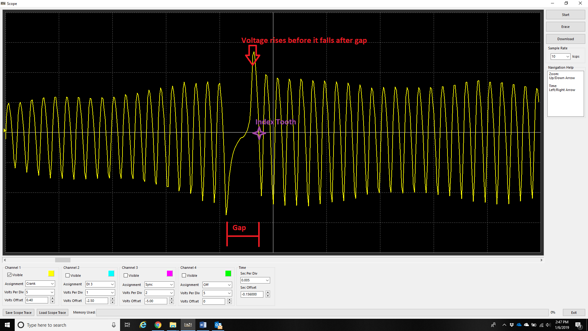
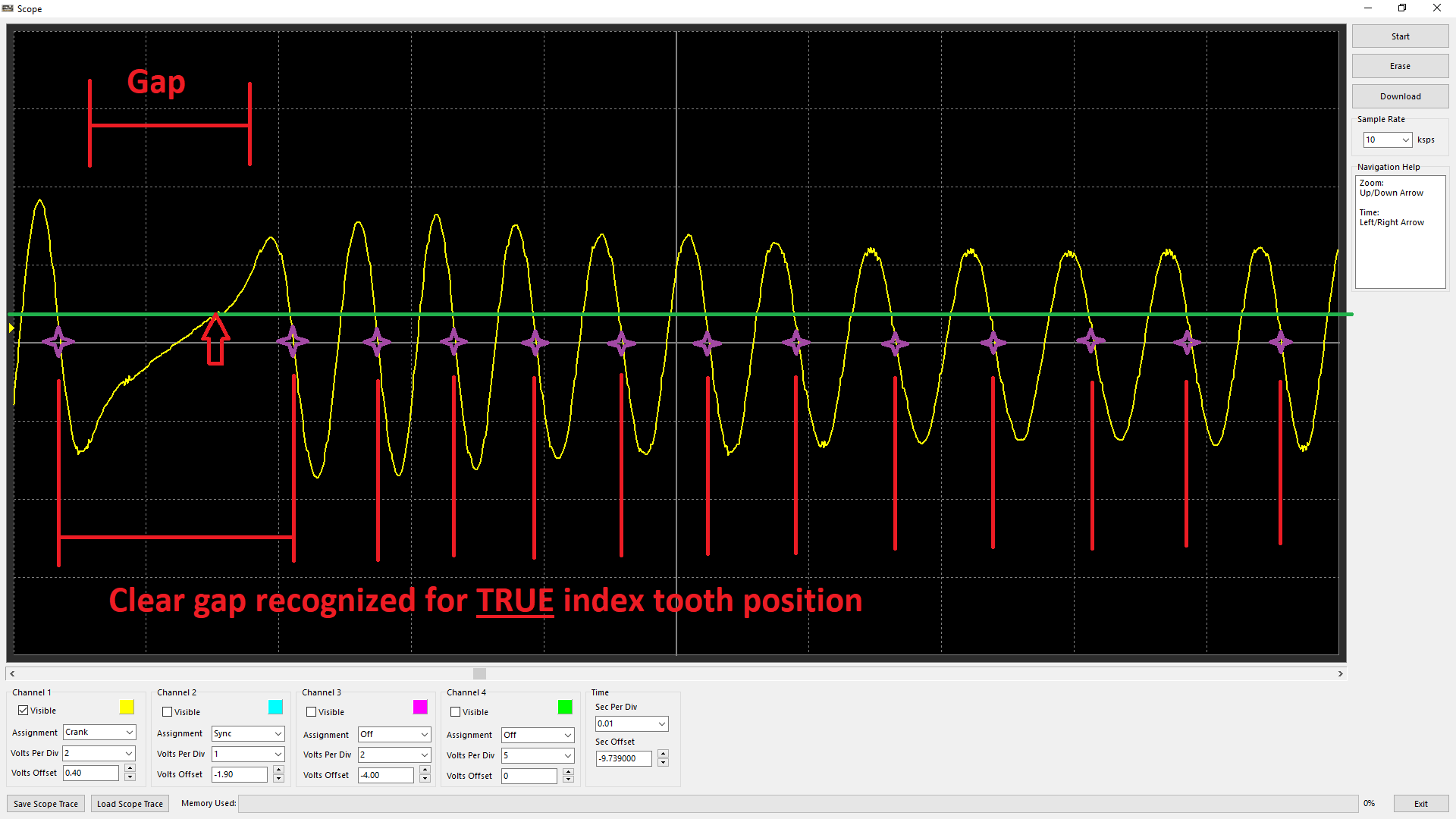
Use the gap to identify the polarity of this crank sensor is correct. Do this by ensuring that the next tooth after the gap rises before it falls.
On a non-missing tooth multi-tooth trigger, the polarity can be validated generally by observing the “fast edge” being the falling edge. The above example shows this where the rising slope of the trace is much slower than the falling slope of the trace. The rising slope also will change based on the speed of the trigger wheel.
** Note – this is also why the falling edge provides most stable timing on magnetic triggers (with correct polarity).
** See Crank Index/Sync Sensor Setup
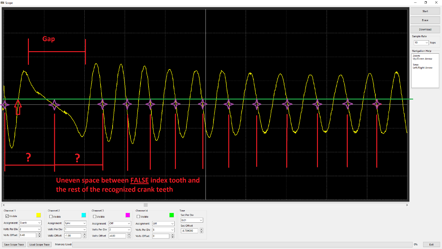
Crank trigger wired with incorrect polarity. Observe the voltage drops as the tooth after the gap approaches instead of rises.
In the case of missing tooth trigger wired with backwards polarity, the index tooth would either be recognized in the wrong position (earlier/before the index tooth has passed), or the “gap” not recognized properly due to not being able to differentiate a clear space. Subsequently this does not allow the ECU to identify the index tooth for timing the engine. Additionally, the uneven spacing (besides the expected “gap tooth number”) will cause the ECU to count crank tooth errors. The gap between the “false” index tooth position/gap and evenly spaced teeth will change with RPM as well.
Crank trigger wired with correct polarity. Observe the voltage rises as the tooth after the gap approaches.
With the polarity correct, it is clear the gap can be recognized, and the index tooth is being appropriately recognized at the true position (tooth after the gap).
Improper Edge Configuration for Crank/Sync Sensor
Falling Edge
With correct sensor polarity, both magnetic and hall sensors should have falling edge polarity in most cases. This is because these sensors have consistent “fast” performance when the tone ring teeth pass the sensors.
An example of a magnetic sensors fast edge being the falling.
An example of a hall senor fast edge being the falling. Most hall sensors produce a very good “square” wave, so the point can be argued that rising edge can be used, however at higher revs some will produce this “saw tooth” pattern which means triggering that way will cause timing to wander.
Rising and Falling Edge Sync Mode
Engines with multi-tooth sync sensors usually will have a “long” tooth during the “crank index point”. Normally, a custom decoding mode is needed to run the engine with multiple sync teeth, but in this case because there is a clear difference in signal on the sync input on each stroke (low vs high), the ECU can determine the stroke immediately (this is the fastest way to decode starting/720 sync). Set Sync Sensor Edge configuration to Rising and Falling for these trigger types.
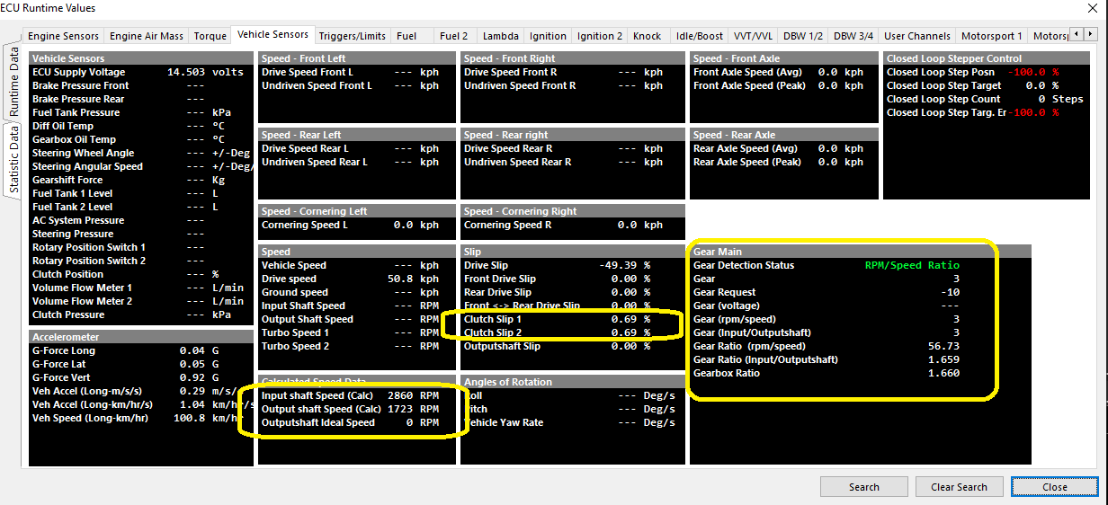
This means the Input Shaft is rotating 4.06% slower than the Engine Speed… i.e 4.06% Clutch Slip.
Drive Slip Calculation
Drive Slip
Given as a percentage of the difference between the speed of the driven wheel compared to the speed of an undriven wheel. The Drive Slip can be both positive and negative.
The ECU will average the front wheel speed and load this value into the runtime " Front Axle Speed"
The ECU will average the rear wheel speed and load this value into the runtime " Rear Axle Speed"
Driven Speed Channel = Rear Axle Speed
Undriven Speed Channel = Front Axle Speed
Turning Slip
The difference between the wheel speeds on the left side of the vehicle and the wheel speeds on the right side of the vehicle. The ECU uses “Front Axle Speed” and “Rear Axle Speed” to calculate this.
ECU calculated values: If sufficient Input Speed channels are selected the ECU can calculate the following addition data.
Front Axle Speed.
The average of either:
The Drive Speed Front L and R or
The Undriven Speed Front L and R
Rear Axle Speed.
The average of either:
The Drive Speed Rear L and R or
The Undriven Speed Rear L and R
Cornering Speed L.
The average of the Speed Front L (driven or undriven) and Speed Rear L (driven or undriven)
Cornering Speed R.
The average of the Speed Front R (driven or undriven) and Speed Rear R (driven or undriven)
NOTE: The ECU will check which speed channels are assigned and use this information to calculate the data. For this to work correctly for example the Speed Front L Driven and Undriven channels can never both be selected.
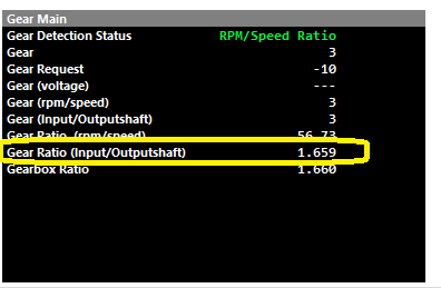
Gear Management
Gear Management
The first step to proper gear management/detection is a properly scaled and validated speed signal.
Gear Management in Emtron can be detected in various ways.
Fundamentally, gear control and detection are a part of the ECU functions.
Several channels are linked to the gear functions that can be viewed, logged, and used as active channels :
Gear Position (RPM/Speed) Setup
Speed Lockout
Gear Detection Ratio Calculation stops when the speed fall below this value.
0 = OFF
Typical: 2-5.
Default Gear
Default gear for Gear Detection Ratio Calculation.
Gear Valid Time
Typical: 10ms
Tolerance
Typical: 10%
Fault Time
Fault Time for Gear Detection Ratio Calculation.
Typical: 1000ms
Clutch Switch Lockout
Gear Ratio Detection Calculation temporary stops when the Clutch Switch is ON i.e. during a gear change.
Clutch Switch Input Channel MUST be configured
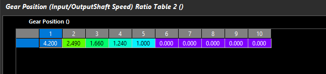
Gear Position (RPM/Speed) Table
Define the multiplier here to get speed for the ratio calculation to work. IE:
100kph *34 in 5th gear = 3400rpm.
Speed channel must be configured and scaled
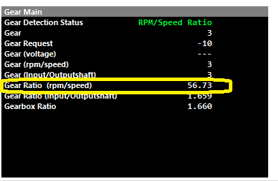
RPM/Speed ratio is also actively calculated in Runtimes
In both Speed Density and MAF modes the ECU performs the following steps to calculate the final Injector OpeningTime.
Calculate the Air Mass per cylinder.
In Speed Density Mode PV = nRT is used to Calculate Air Mass.
In MAF mode, Air Mass is measured directly from the MAF Sensor.
In Throttle Mass Flow (TMF) mode the Air Mass is calculated by looking at the pressure ratio across the throttle body, calculating the
throttle area and applying these to a 2nd order thermodynamics equation.
Calculate Fuel Mass using Air Mass, Stoichiometric ratio, Lambda Target, Engine VE and other parameters outlined below.
Calculate Effective Pulse Width using Fuel Mass, Injector Mass Flow, Fuel Density and Bernoulli’s equation for Fuel Pressure correction.
Fuel Model: Charge Temp
This setting ONLY applies when the Fuel Model is selected to Speed Density. There are 2 separate methods that control how the fueling is adjusted based on Charge Temperature.
With this setting set to ON (and this is the recommended setting) the Charge Temp will be used to adjust the Air Mass as part of the Ideal Gas Law equation. The ECU is then able to automatically adjust the Air Mass (g) based on this temperature.
When this setting is OFF the Air Mass is not modified base on Charge Temp. Instead the Tuning View -> Compensations -> Charge Temp Comp Table 1 can be used to manually correct the fueling based on Charge Temperature.
NOTE: It is NOT recommended to have both systems ON at the same time.
Fuel Model: Fuel Pressure
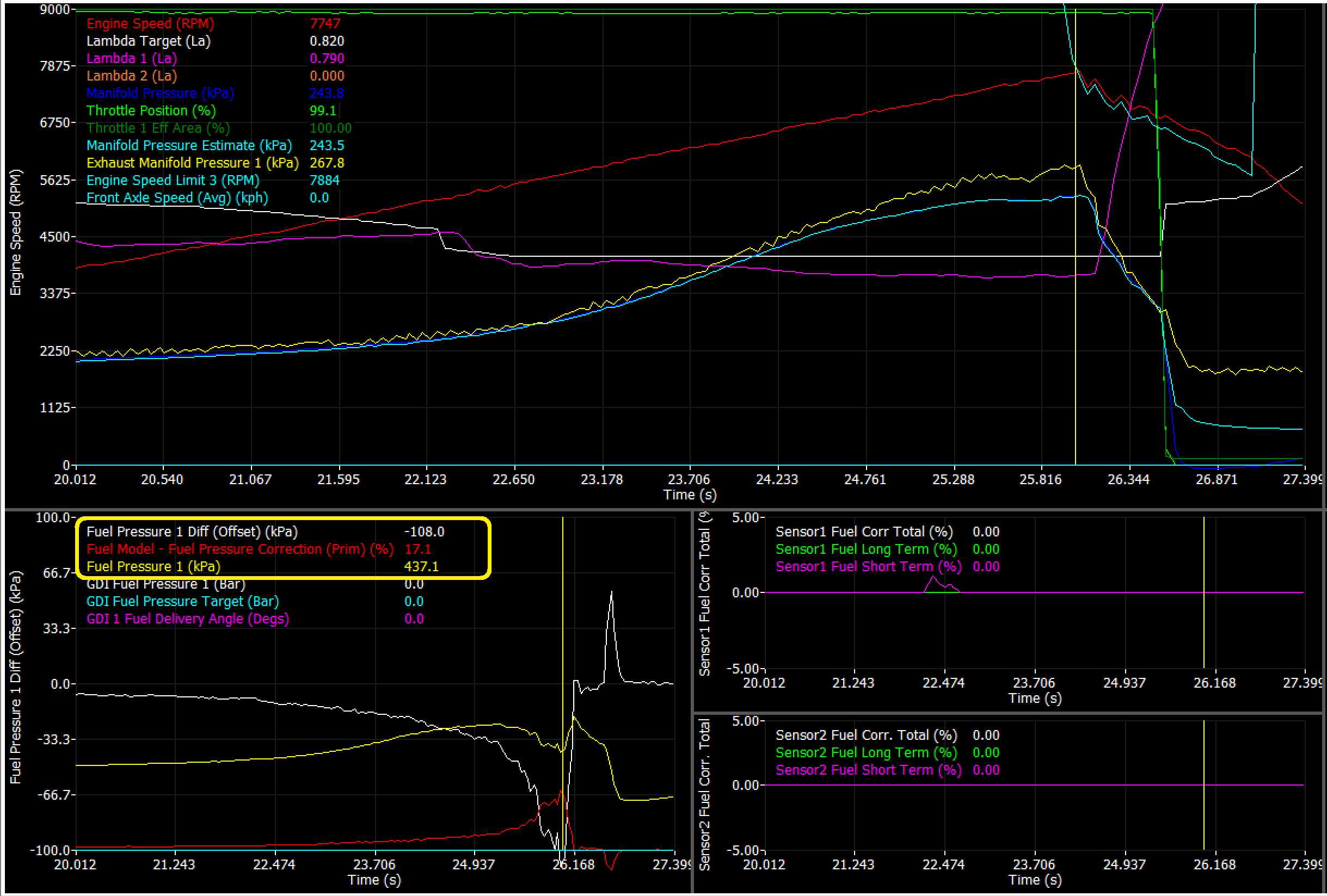
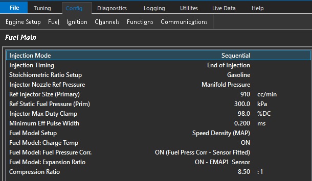
This setting applies to ALL Fuel Models. A Fuel Pressure Sensor MUST be fitted. The ECU will correct/adjust the Injector Flow as the differential pressure across the injector changes. This means any fuel surge causing an sudden drop in fuel pressure the ECU can correct the fueling and maintain the correct mixture.
NOTE: Fuel Pressure Units MUST be in kPa to match both the MAP and BAP units.
Sensor Requirements
Additional to MAP and MAF the following sensors should be used to take full advantage of ECUs Fuel Model(s):
Fuel Temperature.
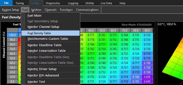
Used to help accurately calculate Fuel Density (g/ml) by spanning the x-axis on the Fuel Density Table (see Config View -> Fuel -> Fuel Density Table). See Figure 1 below.
If the Fuel Temp channel is not selected it defaults to 20 DegC which will then be used to span the Fuel Density Table. Note: If an Ethanol Sensor is selected the Fuel Temp information from the sensor is automatically copied into the Fuel Temp Runtime.
Figure 1: Fuel Density Table
Fuel Pressure Sensor.
Required if Fuel Pressure Correction is to be used.
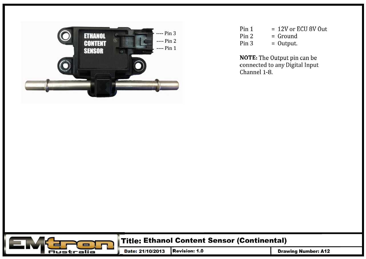
Ethanol Sensor
Strongly recommended to use this sensor when running Ethanol based fuels. It allows the ECU to automatically correct fueling based on Ethanol Content. i.e Petrol (0% Ethanol) up to 100% Ethanol. It does this by adjusting the Fuel Density and Stoichiometric Ratio . See Figure 1.
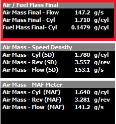
The Final Air and Fuel Mass used by the ECU can be viewed from the Runtime menu -> Fuel Tab (F3). You can also view data from the Speed Density (SD) and MAF Sensor Calculations. See Figure 2.
Figure 2. Final Mass values (Fuel and Air) shown in red box.
Fuel Model Modes
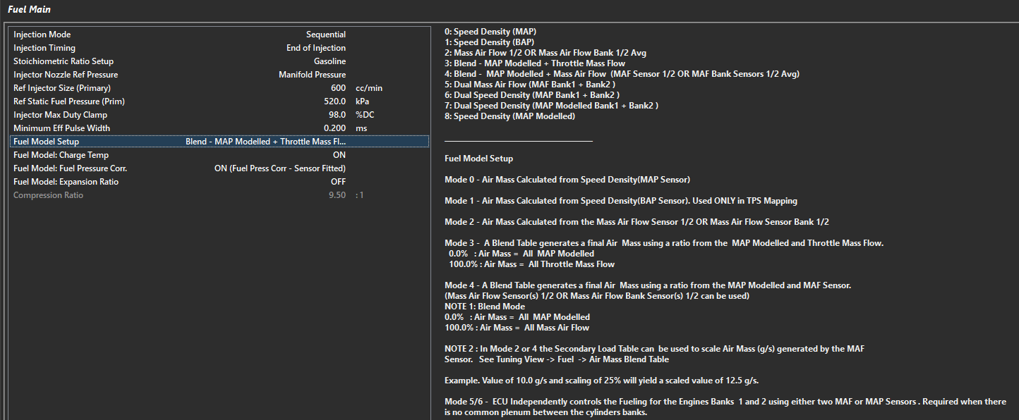
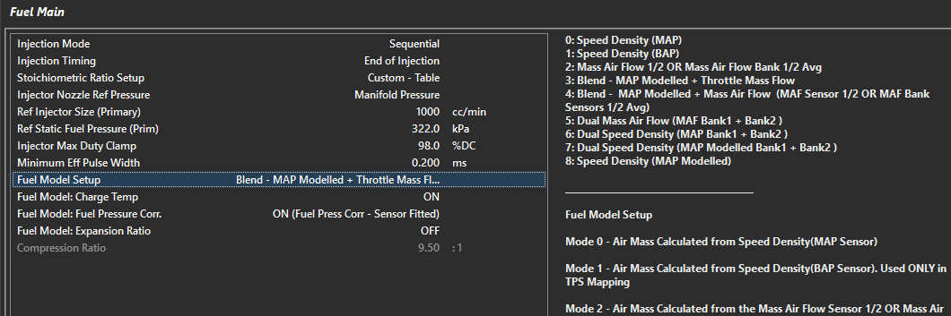
To configure the Fuel Model select the appropriate method from the Config View -> Fuel -> Fuel Main -> Fuel Model Setup
Air and Fuel Mass Modifier Tables
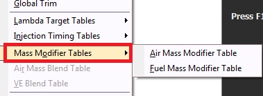
There are additional Tables available to modify the Air Mass and Fuel Mass if required. These can be switching ON from Tuning View -> Fuel Table Control -> Mass Modifier Tables. See Figure 3.
Figure 3: Mass Modifier Tables
Fuel Model: Fuel Pressure
Fuel Model : Fuel Pressure
Fuel Model: Fuel Pressure Corr.
Fuel Pressure Correction - Primary Injectors
** Secondary Injectors configured separately
Includes the Fuel Pressure in the Fuel Model Calculation. The ECU is able to automatically adjust the Mass Injector Flow based on the differential pressure across the Injector.
** NOTE: ONLY uses Fuel Pressure 1 Input Channel **
0: OFF
1: ON (Fuel Press Corr - Sensor Fitted)
2: ON (Static Fuel Pressure - No Sensor)
0 = ECU will not correct fuel mass at all. This means the Fuel Mass Calculation is functioning solely off the Ref Injector Size (Primary) and Ref Static Fuel Pressure (Prim).
** Using a Vacuum Referenced (rising/falling rate regulator) should provide stable differential pressure.
1 = ECU will calculate new fuel mass requirements based on deviation from Ref Static Fuel Pressure (Prim) value.
2 = ECU will calculate differential pressure loss (without a sensor) assuming the Ref Static Fuel Pressure (Prim) cannot be maintained due to having a non-vacuum referenced/rising rate fuel pressure regulation system installed (static pressure all the time).
Channels to reference :
Fuel Pressure 1 - Pressure value generated by calculated channel - as calibrated by input setup
Fuel Pressure 1 Diff - Effective/Relative/Differential pressure across injector - uses Injector Nozzel Ref Pressure to calculate
Fuel Model - Fuel Pressure Correction (Prim) % - Percentage of Fuel Mass correction applied due to Fuel Pressure 1 Diff Offset
**** Recommended Setting - “1” due to Vacuum Referenced regulators not always providing 1:1 pressure change vs Injector Nozzle Ref Pressure and other inadequacies of most fuel systems (starvation, voltage supply, out-flowing, etc)**
Example demonstrating loss of fuel pressure and ECU compensating fuel mass until specified “cut off - Fuel Pressure Engine Protection
** Observe Lambda staying on target with negative Fuel 1 Diff Offset, and Positive Fuel Model - Fuel Pressure Correction (Prim)
Fuel Density Table
Fuel Density Table
The Fuel Density Table is utilized by the Fuel Model to determine the fuel mass.
Fuel Temperature has a major influence on the fuel density and hence the mass of the fuel.
This 3D table can also account for fuel density changes based on any parameter in the ECU.
This setting is particularly useful when using multiple fuel compositions such as ethanol which also influence the fuel mass.
The Emtune software has pre determined Fuel Density Tables available in it that are only a right click of the mouse away
By selecting “Load Table” you can quickly arrive at the correct density table to suit commonly used fuels.
The Ethanol Fuel Density Table.etf is as shown in the example above & spans the increase in ethanol against gasoline.
Methanol & Gasoline specific Fuel density tables are also included.
Fuel Main
Fuel Model Blending control
Fuel Model Blending Control
The Fuel Model Blending Control Table is available when “Blend” modes are being used.
Common uses for Fuel Model Blending would be when switching between MAF and Speed Density (when MAF resolution may become ineffective for the application), or Throttle Mass Flow and Speed Density (when Throttle Pressure Ratio doesn’t support TMF measurement).
** Note the Blend Function actually connects to MAP Modeling which allows for further blending of fuel model modes additionally. See - MAP Modeling
Select “blending” - Modes 3 or 4 in :
Config -> Fuel -> Fuel Model Setup
This table is available for the user to control the ratio of which model is used.
MODE 3:
0.0% : Air Mass = All MAP Modelled
100.0% : Air Mass = All Throttle Mass Flow
MODE 4:
0.0% : Air Mass = All MAP Modelled
100.0% : Air Mass = All Mass Air Flow Sensor
Fuel Secondary Setup
Fuel Secondary Setup
Fuel Table Control
Fuel Table Control
Tuning -> Fuel -> Fuel Table Control
The fuel table control allows you to tailor the number of fuel tables used and how they are utilized.
There are 3 Main VE tables available, they can be used individually, on a user selectable cal slot
(Example: The position of the Si Drive selector in a Subaru Sti over the CAN BUS)
On a user defined Z-Axis (Example: Spanned across ethanol content)
Or a user defined blend across tables based on specified parameters.
This allows a user defined level of complexity
Main VE Fuel Table Control Tab shown as an example.
This level of complexity flexibility is common to all fuel control tables.
Compensation Tables:
The compensation tables offer the tuner the ability to compensate for a wide range of variable conditions
All compensation tables are user definable 3D tables that can be utilized against any runtime
More commonly used compensations are already named & linked to their specific purpose
With 2 additional User Comp tables where all parameters are defined by the user.
Sequential Primary Injectors: Allocated on Injection Channels 1-8.
Sequential Secondary Injectors: Allocated on Injection Channels 9-16.
**** Staging mode must have primary cylinders start with Cylinder 1**
Injection Mode = Non Sequential
In this mode the odd injector channels are fired on one cycle, and even injector channels on the next. The ECU will calculate fuel mass required and divide it by the number of cylinders NOT the number of injector channels.
**** Cylinder numbering, bank assignment, firing order is disregarded in this injection mode**
Example 1:
6 injectors connected individually on a 6 cylinder engine
ECU will activate 1+3+5 on one TDC, 2+4+6 on the next (odd and even)
Example 2:
6 injectors connected individually on a 6 cylinder engine but ordered so the cylinders fire per bank
If the engine has dual banks (123 / 456), and the firing order is 1536242, the installer can re-order the cylinders vs injector outputs to synchronize firing per bank
ECU will activate 1+3+5 on one TDC, 2+4+6 on the next (odd and even)
Injection Channels 123456
Cylinder Numbers 142536
This will fire 1+2+3 cylinders on one cycle, 4+5+6 on the next
8 injectors connected individually on a 8 cylinder engine but ordered so the cylinders fire per bank
If the engine has dual banks (1357 / 2468), and the firing order is 18436572, the installer can re-order the cylinders vs injector outputs to synchronize firing per bank
ECU will activate 1+3+5+7 on one TDC, 2+4+6+8 on the next (odd and even)
Injection Channels 12345678
Cylinder Numbers 12345678
If the engine has dual banks (1234 / 5678), and the firing order is 15486372, the installer can re-order the cylinders vs injector outputs to synchronize firing per bank
ECU will activate 1+3+5+7 on one TDC, 2+4+6+8 on the next (odd and even)
Injection Channels 12345678
Cylinder Numbers 15263748
ECU will activate 1+2+3+4 on one TDC, 5+6+7+8 on the next (odd and even)
Example 3:
2 injectors connected with 3 injectors paired to each output on a 6 cylinder engine
Engine will fire output 1 on one TDC, 2 on the next
The installer can group the cylinders they want to fire on each cycle
** This method will NOT provide the best injector deadtime and linearization control.
Injection Mode = Sequential/Staged Group
WARNING:
DO NOT use Fuel Engine Limiting when Staged Injection is enabled.
If there is an Injection Phasing difference between Primary and Secondary Injectors,
Cut synchronization is not always possible and may result in engine damage.
Ignition Liming is recommended.
In this mode the Primary Injectors are sequential and the Secondary Injectors are Group/Non sequential. The Secondary Injectors are opened once per engine cycle. The Secondary Odd and Even Injection channels are run anti-phase. The Injectors on Even Channels are started at 0.0 Degrees BTDC. The Injectors on Odd Channels are started at 360.0 Degrees BTDC
Cylinder (Prim) = Enter the cylinder number for each Injection Channel connected to a primary injector
Inj Count (Sec) = Enter the number of secondary injectors connected to an Injection Channel. This is group staged and is NOT referenced to cylinders.
Example 3:
Sequential Primary Injectors: Allocated on Injection Channels 1-4.
Grouped Secondary Injectors: One injector on each Injection Channel 5,6,7,8
Example 4:
Sequential Primary Injectors: Allocated on Injection Channels 1-8.
Grouped Secondary Injectors: Two injectors on each Injection Channel 9,10.
Injector Deadtime Table
Injector Dead Time Table
The Injector Dead Time Table is utilized by the ECU to compensate for the latency (or Deadtime) of the Primary injectors
The injector deadtime is the time factor in milliseconds when no fuel is injected accounting for the reaction time of the injector.
Setting the correct deadtime of an injector is critical for ECU fuel mass calculations.
All injectors have a deadtime which may be affected by a number of factors.
The voltage at the injector generally has the highest influence on the injector deadtime.
Other factors such as fuel pressure also have a major affect on the injector deadtime.
Saturated injectors tend to have longer deadtimes when compared to peak & hold injectors
The Emtune software has commonly used Injector Deadtime Tables available in it that are only a right click of the mouse away.
Tuning Tip:
Injector Dead times can be validated using the Emtune Software by using the Wideband Lambda control. If you add 10% to your VE table (@ 3000rpm / 80kpa load for example), you should see a corresponding negative 10% trim applied via the Wideband lambda control. If you don’t, then you know your dead times need some attention.
By utilizing a dead time table available in your Emtune software that is close. The correct dead time for your injector can be quickly arrived at by simply globally moving the table up & down. The voltage slop of the dead times can be further validated by removing the alternator charge and allowing the supply voltage to drop away. Correct dead times allow the engine to operate correctly over a wide range of variable conditions
Injector Driver Setup
Injector Driver Setup
The Injector Driver Setup is where the injector driver output is configured.
For High Impedance or Saturated injectors the Saturated setting should be used
KV based ECU’s also have the ability for user defined Peak and Hold setting.
Peak & Hold refers to low impedance injectors that require significantly more current to run correctly
Peak and Hold Examples:
Peak Current = 4A
Peak/Hold Ratio = 4. This gives 4A/4 = 1A Hold Current
Peak Current = 6A
Peak/Hold Ratio = 6. This gives 6A/6 = 1A Hold Current
Peak Current = 6A
Peak/Hold Ratio = 1.5. This gives 6A/1.5 = 4A Hold Current
The Custom setting allows for individual injector channel setup
Injector Linearisation Table
Injector Linearisation Table
The Injector Linearisation table is a low pulse adder table which uses offset values that vary with pulsewidth, correcting the lower non linear operating range of the injector. Its only used a small pulsewidths and this data is available from most injector manufactures.
The Emtune software has commonly used Injector Linearisation Tables available in it that are only a right click of the mouse away
Injector Max Duty Clamp
Injector Max Duty Clamp
Clamps the Injector Duty Cycle.
NOTE:
The runtime Injector Duty will show past this value as it represents the duty cycle required to achieve the current pulse width.
This maximum duty clamp value applies to both primary & secondary injectors when using staged injection mode
Injector Nozzle Ref Pressure
Injector Nozzle Ref Pressure
0: Manifold Pressure
1: Manifold Pressure - Bank 1
2: Manifold Pressure - Bank 2
3: Manifold Pressure Bank 1/2 Avg
4: Boost Pressure - Bank 1
5: Boost Pressure - Bank 2
6: Boost Pressure Bank 1/2 Avg
7: Barometric Pressure (Inj Before Plate)
Sets the reference against which injector differential pressure is measured
Injector P/H Advanced
Injector P/H Advanced
Injector Peak and Hold Advanced
This feature allows for user definable hold current & transition timing control of low impedance injector drivers
This is an advanced feature for experienced tuners only.
Ref Injector Size (Primary)
Ref Injector Size (Primary)
Flow rating of the primary injectors in cc per minute at the primary reference static fuel pressure
Ref Injector Size (Sec)
Ref Injector Size (Sec)
Flow Rating of the Secondary injectors
at the reference static fuel pressure
Ref Static Fuel Pressure (Prim)
Ref Static Fuel Pressure (Prim)
Reference static fuel pressure is set without the engine running at the current barometric pressure.
It is important that this setting is correct especially when the fuel pressure is enabled as part of the “fuel model”.
The ECU will correct the fueling if the fuel pressure goes above or below the differential fuel pressure.
The “Differential Fuel Pressure Offset” should be 0 or close to under normal operating conditions.
When “Fuel Model: Fuel Pressure” setting is ON
Provides a Diff Fuel Pressure Offset runtime.
Ref Static Fuel Pressure (Sec)
Ref Static Fuel Pressure (Sec)
Static reference pressure of secondary injectors
Secondary Injector Deadtime Table
The Injector Dead Time Table (Sec) is utilized by the ECU to compensate for the latency (or Deadtime) of the Secondary injectors
The injector deadtime is the time factor in milliseconds when no fuel is injected accounting for the reaction time of the injector.
Setting the correct deadtime of an injector is critical for ECU fuel mass calculations.
All injectors have a deadtime which may be affected by a number of factors.
The voltage at the injector generally has the highest influence on the injector deadtime.
Other factors such as fuel pressure also have a major affect on the injector deadtime.
Saturated injectors tend to have longer deadtimes when compared to peak & hold injectors
The Emtune software has commonly used Injector Deadtime Tables available in it that are only a right click of the mouse away.
Tuning Tip:
Secondary Injector Dead times can be validated using the Emtune Software by using the Wideband Lambda control. Once the secondary blend is biased 100% towards the secondary injectors. If you add 10% to your VE table (@ 3000rpm / 80kpa load for example), you should see a corresponding negative 10% trim applied via the Wideband lambda control. If you don’t, then you know your dead times need some attention.
By utilizing a dead time table available in your Emtune software that is close. The correct dead time for your injector can be quickly arrived at by simply globally moving the table up & down. The voltage slop of the dead times can be further validated by removing the alternator charge and allowing the supply voltage to drop away. Correct dead times allow the engine to operate correctly over a wide range of variable conditions
Starting Tables
Emtune has multiple tables for many engine functions. The table behavior is based on comprehensive selections in Tuning under the respective function (IE, Fuel, Ignition, DBW, Cam control). Some functions have many tables that can be enabled such as Fuel and Ignition tabs. These main functions allow you to enable a variety of compensations, modifiers, individual trims, and more.
For main table controls, the selections are mostly universal.
(Fuel example shown)
Not all of the above example will be available for every function, but generally most functions are the same.
**ON – Table *** enable those respective tables always.
Cal Slot enables which table is currently being commanded by the Cal Slot Control (see Cal Slot Control)
Z-Axis uses a separate X axis lookup that can allow the blending of all the available tables.
Any runtime can be used, and the units equal which table to run in this case. You can see in the above example the ECU will switch (and interpolate in between) the three different tables available based on TP1 position.
*** Blend** tables allow switching between two tables only.
Stoich Ratio Setup
Stoich Ratio Setup
Used as part of the Fuel Model in conjunction with the Lambda Target to determine the required Fuel Mass.
Units: AFR
0: Default: 14.70 AFR
1: Custom - Table
2: Gasoline
3: E85 Alcohol
4: E100 Alcohol
5: Methanol
6: Propane
7: Diesel
A custom table allow the user to adjust the Stoich in real-time as the Fuel-type changes. An Ethanol example is shown below.
Stoichiometric Custom Table
Stoichiometric Custom Table
Gasoline to Ethanol Stoichiometric Custom Table example shown - available to load in Emtune software
This table is used by the ECU to determine the stoichiometric fuel ratio.
This is critical when multiple fuel compositions are used.
The most common application of this table is in a multi fuel system which uses a flex meter to determine the alcohol content.
Selects the ignition output strategy used by the engine. The selected ignition mode determines how ignition events are distributed across the available ignition output channels.
⚠️ Warning
The ECU Ignition Output provides a TTL-level trigger signal intended to control an external ignitor or a coil with an integrated ignitor module.
Do not connect the ECU Ignition Output directly to a coil negative terminal. Incorrect connection will result in damage to the ECU and/or ignition system.
Options
Value
Mode
0
Off
1
Direct Fire
2
Wasted Spark
3
Distributor
4
Twin Distributor
5
Direct Fire + Direct Trailing Spark
6
Wasted Spark + Direct Trailing Spark
7
CDI 8
Mode Descriptions
Off
Disables all ignition outputs.
Direct Fire
Each cylinder is assigned its own dedicated ignition output channel.
Wasted Spark
Each ignition output fires two cylinders simultaneously, with one spark occurring on the compression stroke and the other on the exhaust stroke.
Distributor
Uses a single ignition output to drive a conventional distributor ignition system.
Twin Distributor
Uses two ignition outputs to drive a twin distributor ignition system.
Direct Fire + Direct Trailing Spark
Provides individual ignition outputs for both leading and trailing spark plugs. Commonly used on rotary engines requiring independent control of leading and trailing ignition events.
Wasted Spark + Direct Trailing Spark
Uses wasted spark ignition for the leading plugs while maintaining individual control of the trailing spark plugs.
CDI 8
Configures the ECU for operation with an external 8-channel Capacitive Discharge Ignition (CDI) system.
ℹ️ Note
Ignition Channel 1 is the only ignition output available in Distributor mode.
Ignition Channels 1 and 2 are the only ignition outputs available in Twin Distributor mode.
For Direct Fire + Direct Trailing Spark and Wasted Spark + Direct Trailing Spark modes, a maximum of 6 trailing ignition channels are available.
All other ignition modes provide fully configurable ignition channel assignments.
Selects the ignition output edge used by the ECU to trigger the ignition firing event.
The selected edge defines the polarity of the ignition control signal. One edge initiates coil charging (Dwell Edge) while the opposite edge commands the ignition coil to discharge and generate the spark (Firing Edge)
Warning.
Ensure the correct ignition edge is selected before connecting the ECU to the ignition system.
Selecting the incorrect edge may result in damage to the ECU, ignition module, ignition coil(s), or associated wiring.
The ECU Ignition Output provides a TTL-level trigger signal intended to control an external ignitor or a coil with an integrated ignitor module.
Do not connect the ECU Ignition Output directly to a coil negative terminal. Incorrect connection will result in damage to the ECU and/or ignition system.
Options
Value
Mode
Description
0
Falling
Coil charging begins on the Rising Edge and the spark is fired on the Falling Edge.
1
Rising
Coil charging begins on the Falling Edge and the spark is fired on the Rising Edge.
ℹ️ Typical Configuration
Most modern ignition coils and ignition modules incorporate an internal ignitor and require a Falling Edge spark output.
Ignition MBT Reference
Overview
Selects the ignition table that represents MBT (Minimum Spark Advance for Best Torque).
MBT is defined as the ignition timing that produces the maximum engine torque for a given engine speed and load operating point. Additional ignition advance beyond MBT will typically provide little or no increase in torque, while ignition timing retarded from MBT will result in a reduction in engine torque output.
ℹ️ Why is MBT Required?
The ECU Engine Torque Model requires a reference for the ignition timing that produces maximum engine torque at each engine speed and load operating point. The selected MBT reference table provides this reference and defines the maximum available engine torque for the Engine Torque Model.
By comparing the active ignition timing against the MBT reference table, the ECU can determine when the engine is operating below its maximum torque potential due to ignition retard and apply the appropriate correction to the calculated engine torque.
The ECU continuously calculates the difference between the active ignition timing and the configured MBT reference table:
Negative Offset = Ignition timing is retarded relative to MBT, resulting in a reduction in the ECU calculated engine torque.
Positive Offset = Ignition timing is advanced beyond MBT and will typically result in little or no increase in engine torque.
Options
Value
Mode
0
Off
1
Table 1
2
Table 2
Off
Disables MBT referencing. The Engine Torque Model assumes no torque reduction due to ignition retard.
Table 1
Uses Ignition Table 1 as the MBT reference table.
Table 2
Uses Ignition Table 2 as the MBT reference table.
ℹ️ Recap
When the MBT Offset becomes negative, the active ignition timing is retarded relative to the MBT reference timing. As a result, the ECU determines that the engine is operating below its maximum torque potential and applies a corresponding reduction to the calculated engine torque used by the Engine Torque Model.
The MBT reference table should represent the ignition timing required to achieve maximum engine torque.
If dual ignition tables are used for different fuel types, such as Petrol and E85, the ignition table representing the highest achievable engine torque should generally be selected as the MBT reference table.
Since E85 typically requires greater ignition advance to achieve MBT than an equivalent Petrol calibration, the E85 ignition table will often be the preferred MBT reference.
Dwell Setup
Dwell Setup
Overview
There are two Dwell Tables available. This setting determines which Dwell Table is assigned to each cylinder.
In most applications all cylinders will use the same Dwell Table. However, multiple dwell tables can be useful when different ignition coil types are used, or when leading and trailing ignition systems require different dwell characteristics.
Dwell Tables
Overview
The Dwell Table defines the ignition coil charge time (dwell) as a function typically of ECU Supply Voltage and Engine Speed.
Dwell time is the amount of time the ignition coil primary winding is energised prior to the spark event and is expressed in units of milliseconds (ms).
During the dwell period, energy is stored within the ignition coil magnetic field and is subsequently released when the ignition event occurs. Insufficient dwell time may result in a weak spark and ignition misfire, while excessive dwell time can overheat the ignition coil and ignition driver circuitry.
Two independent Dwell Tables are available and can be assigned to individual cylinders using the Dwell Setup configuration page. See Dwell Setup for more infomration.
ℹ️ Note
Excessive dwell time does not generally increase spark energy once the ignition coil has reached magnetic saturation and may result in unnecessary heating and/or failure of the ignition coil and ignition drivers.
Dwell Offset Table 1
The Dwell Offset Table 1 is a user-defined offset table that allows ignition coil charge time (dwell) to be adjusted based on operating conditions or factors not directly accounted for by Dwell Table 1.
Dwell Table 1 supports a user-defined Dwell Offset Table. Dwell Table 2 does not have an associated offset table and uses the base dwell values defined within the table only.
Ignition Test
Overview
The Ignition Test function allows each ignition output channel to be manually fired for installation, diagnostics and troubleshooting purposes.
This function can be used to:
Verify ignition coil wiring.
Confirm cylinder numbering and firing order.
Check ignition output operation.
Verify spark plug and ignition coil functionality.
Diagnose ignition system faults.
The Ignition Test Dwell setting specifies the coil charge time used during the test event and is expressed in units of milliseconds (ms). A test dwell value of 3.0 to 4.0 ms is suitable for most modern inductive ignition coils.
When an ignition channel test is activated, the ECU charges the selected ignition coil for the configured test dwell period before firing a spark event. The test rate runs at 10Hz
The ignition test function operates at a fixed test rate of 10 Hz (10 ignition events per second).
⚠️ Warning
The Ignition Channel Output must have a cylinder assigned for this function to operate. See See Ignition Channel Setup for help.
Ensure the ignition system is configured correctly before performing an ignition test.
High voltages are generated during ignition testing which may cause injury or damage to ignition components if used incorrectly.
Do not perform ignition tests in the presence of fuel vapour or near flammable materials.
Ignition Channel Setup
Overview
The Ignition Channel Setup table assigns each ECU ignition output channel to an engine cylinder number.
This configuration determines which ignition output is used to fire each cylinder.
A value of 0 indicates that the ignition output is not assigned to a cylinder and is therefore available for use by other ECU functions.
ℹ️ Note
The ignition channel assignments are independent of the engine firing order, which is configured separately using the Engine Firing Order settings. See Firing Order Setup
In most applications the ignition outputs are wired sequentially to simplify installation and diagnostics:
Ignition Output 1 → Cylinder 1
Ignition Output 2 → Cylinder 2
Ignition Output 3 → Cylinder 3
etc.
However, the ignition outputs may be assigned in any order to suit the wiring requirements of the installation.
Wasted Spark Configuration
For Wasted Spark applications, assign only the first cylinder in each firing pair to the ignition channel.
The ECU automatically determines the corresponding paired cylinder from the configured Engine Firing Order and generates the required wasted spark pairing and fills in the assignment table accordingly
The ignition channels should be assigned in engine firing order sequence.
Assign Ignition Channels as shown below (regarding above firing order). Enter cylinder 1 into Ignition Channel 1 and the ECU will automatically also assign its pair, cylinder 6. Likewise enter cylinder 5 into Ignition Channel 2 and the ECU will automatically assign its pair, cylinder 2 etc.
Ignition Main
Overview
Ignition Main allows for configuring the ECU to suit the engine’s ignition system.
The following settings are configured in this menu item :
Ignition Mode
Ignition Firing Edge
Ignition Current Source
Ignition Advance Clamp
Ignition Retard Clamp
Ignition Spark Duration
⚠️ Warning
The ECU Ignition Output provides a TTL-level trigger signal intended to control an external ignitor or a coil with an integrated ignitor module.
Do not connect the ECU Ignition Output directly to a coil negative terminal. Incorrect connection will result in damage to the ECU and/or ignition system.
Controls the available current drive capability for all Ignition Channels
The ECU provides two selectable ignition output current modes:
Standard Current Mode 35mA at 5V
High Current Mode 70mA at 8.2V
High Current mode provides increased drive capability for ignition systems that require a higher input current (for example one ignition output driving two ignitors).
Ignition Advance Clamp
Limits the maximum ignition advance that the ECU is permitted to command.
If the final ignition timing calculation exceeds this value, the ignition timing will be clamped to the configured advance limit.
This function can be used to protect the engine from excessive ignition advance due to calibration errors, sensor failures or unexpected operating conditions.
Example:
Calculated Ignition Timing = 49°
Ignition Advance Clamp = 45°
Final Ignition Timing = 45°
Ignition Retard Clamp
Limits the maximum ignition retard that the ECU is permitted to command.
If the final ignition timing calculation is retarded beyond this value, the ignition timing will be clamped to the configured retard limit.
This limit is applied to the final ignition timing calculation after all ignition corrections, compensations and modifiers have been applied.
Allowing sufficient ignition retard range is important for functions that intentionally reduce engine torque using ignition timing retard, for example traction control, launch control and anti-lag etc.
A typical value for this setting is -45° BTDC.
Ignition Spark Duration
Specifies the minimum off-time after an ignition firing event before the ignition coil is permitted to begin charging again.
This ensures the coil remains de-energised long enough for the energy from the previous spark event to fully dissipate before the next dwell period begins.
This setting only applies when the ignition mode is configured as Distributor or Twin Distributor.
Default: 1.0 ms
Ignition Retard Clamp
Ignition Retard Clamp
The minimum ignition timing allowed even if the the calculated output is lower .
Typical : -20 deg
The ECU also provides a Status flag to indication this condition. Open the ECU Runtimes menu (F3) and select the Ignition Tab.
Ignition Spark Duration
Ignition Spark Duration
The user definable time factor after a firing event before the coil can be switched back on.
This function keeps the ignition coil switched off for a fixed time, allowing the energy from the previous firing event to fully discharged.
Default: 1.0ms
0.5ms to 5.0ms time window available
Note: Distributor systems only
Channels
Analog Channels 7-12 have configuration pull-up resistors. Sensors requiring a pull-up such as Engine Temperature or Inlet Temperature should use these channels.
There are two main groups of Input Setup Type - Analog Inputs and Digital Inputs. They are grouped into to standard form types, that are mostly the same for all inputs.
Analog Inputs
Above example shows Manifold Pressure Sensor channel.
Input Source
Choose your input source.
** See ECU Hardware Specifications for assigning the best source for your input channel
Filter
Each input can have its own moving average filter applied.
Pull Up
If the channel has pull up capability, the pull up flag will be available.
Sensor V. Reference
Select number of Analog Inputs have Ratio Metric input functions. Select the 5V V Reference Pin if applicable.
** See Ratio Metric Reference Manual available online
Calibration Type
Customize - via Multii-point table on the right
Pre-defined - Via dropdown list (Predefined Calibration)
Clamp Lo/H
Clamp the Low/High value of the input
Fault Lo/Hi
Set Low/High fault voltages
Detect Time Lo/Hi
Set Low/High detect time for fault values to be effective
Fault Value
Set the substitute value for each individual input when Fault is active
DTC Control
Set DTC (diagnostic trouble code) behavior
Auto Clear
Manual Clear (ECU must be connected to clear fault codes)
DTC Engine Limit
Set the Limp Home Limit Table to be used if DTC is active
Limp Home Table 1
Limp Home Table 2
Off
Fault Table
Some major sensor inputs (MAP, TPS, etc) have the ability to enable “Fault Table”, where in fault mode, substitute values can be more than one value.
When enabling Fault Table, Fault Value becomes inactive. Clicking Edit Fault Table gives the user a larger table to add more than one value for substitute values
Axis for table is open, and as an example you can see for MAP substitute values, the axis is selected to look at TPS vs RPM
Digital Inputs
Above examples show a Brake Switch Input and wheel speed input
Input Source
Choose your input source.
** See ECU Hardware Specifications for assigning the best source for your input channel
Sensor Type
Select the Sensor Type
Magnetic
Hall
Momentary
Status will "latch" whenever the thresholds are satisfied
Switch
Will be active when the thresholds are satisfied
Active Edge
Rising
Falling
Both
Off
Pull Up
If the channel has pull up capability, the pull up flag will be available.
Filter
Filter value
Threshold Mode
2 Point
** Only to be used for switch inputs
Table
Table value dictates voltage crossover where signal is valid (voltage level must be **higher** than this arming voltage)
Used for frequency inputs
Active Edge must be configured correctly

See ECU Hardware Specifications for inputs with configurable table arming thresholds
2 Point On/Off
Voltages in which 2 Point mode thresholds are active
Hardware Specifications
Analog Inputs 1- 14
Input Analog Voltage Range: 0 - 5.0V
12 Bit ADC (4096 points)
1st order 100Hz Low pass filter.
1.22 mV (0.0122V) resolution.
DI 1- 8
Input Analog Voltage Range: 0 - 20.0V
4.88mV resolution (10 bit effective resolution using 20V Range - 1024 points)
Maximum usable analog input voltage: 20.0V
.
DI 9- 14
Input Analog Voltage Range: 0 - 20.0V
19.5 mV resolution (10 bit effective resolution using 20V Range) - 256 points
Maximum usable Analog Input Voltage: 20.0V
Example A. Take MAP sensor 0 - 5V input into the ECU with range of 0.0 kPa to 400.0 kPa (3 bar of boost)
a) Using AN 1- 14 (12 Bit resolution)
MAP Resolution = 400 kPa / 4096 = 0.097 kPa. This means the ECU can measure the pressure actuate to within 0.097 kPa using a 4Bar Map sensor.
b) Using DI 1- 8 (10 Bit resolution)
MAP Resolution = 400 kPa / 1024 = 0.488 kPa. This means the ECU can measure the pressure actuate to within 0.488 kPa using a 4Bar Map sensor.
c) Using DI 9- 14 (8 Bit resolution)
MAP Resolution = 400 kPa / 256 = 1.56 kPa. This means the ECU can measure the pressure actuate to within 1.56 kPa using a 4Bar Map sensor.
Example B. Take EGT 0- 5V input into the ECU with range of 0.0 DegC to 1000.0 DegC
a) Using AN 1- 14 (12 Bit resolution)
EGT Temperature Resolution = 1000 degC / 4096 = 0.24 degrees. This means the ECU can measure the EGT temperature actuate to within 0.24 degrees
b) Using DI 1- 8 (10 Bit resolution)
EGT Temperature Resolution = 1000 degC / 1024 = 0.98 degrees. This means the ECU can measure the EGT temperature actuate to within 0.98 degrees or 1.0 degrees rounded up.
c) Using DI 9- 14 (8 Bit resolution)
EGT Temperature Resolution = 1000 degC / 256 = 3.90 degrees. This means the ECU can measure the EGT temperature actuate to within 3.90 degrees or 4.0 degrees rounded up.
NOTE: The Digital Input voltage channels are normally used to read switch inputs and for ECU self testing procedures. However, DI1-8 channels still has very good resolution at 10 Bit with a 0 - 20V range so pressure and temperature sensors can still use connected to these channels.
Quick Calibrations
Quick Calibrations
Config -> Engine Setup
Calibrate Pedal (for DBW applications), and Throttle Position quickly from these menu choices
** To calibrate DBW plate position (with fully configured inputs/outputs), this is done in the Tuning Section, as generally the PID and other functions must be “tuned” as well - Tuning -> Engine Functions -> Drive By Wire -> DBW 1/2 Configuration
Changing DBW Calibration modes will calibrate the plate. See DBW specific help sections for more information.
Validation of the programmed voltages can be observed under the input setup Config -> Channels -> Input Setup. Find the PP/DBW sensors under the DBW tab, or the TPS sensor under the Engine tab (depending which was calibrated), and you can validate if the programmed voltages are correct if there are any issues.
Make sure the fault settings are correct for swept voltages, and the raw voltages can even be viewed in the default view under the Config tab.
Voltages can also be viewed under F3 Runtimes under Raw Inputs, but also the calculated values can then be validated (Pedal Position %, DBW Servo, Throttle Position %).
TPS Open Calibrate
This function is used to calibrate the Open position of the Throttle Position Sensor (TPS) for cable throttle systems
For DBW systems, the DBW servo position (main & sub) are calibrated in the DBW Setup
To utilise, Left mouse button click on tab (see above example)
When completed, an acknowledgment tab will appear
TPS Closed Calibrate
This function is used to calibrate the closed position of the Throttle Position Sensor (TPS) for cable throttle systems.
For DBW systems, the DBW servo position (main & sub) are calibrated in the DBW Setup
To utilise, Left mouse button click on tab (see above example)
When completed, an acknowledgment tab will appear
PPS Open Calibrate
This function is used to calibrate the Open position of the Pedal Position Sensor (DBW)
To utilise, Left mouse button click on tab (see above example)
When completed, an acknowledgment tab will appear
PPS Closed Calibrate
This function is used to calibrate the closed position of the Pedal Position Sensor (DBW)
To utilise, Left mouse button click on tab (see above example)
When completed, an acknowledgment tab will appear
Barometric Pressure
Filter Settings
FIlter Setting Minimum = 0 (OFF)
FIlter Setting Maximum = 50
Recommended Filter Range = 45
Calculated Runtimes
Main
The Calculated runtimes Main is where the Efficiency Calculation and Load Calculation runtimes are defined.
The runtime is defined by nominating the air mass calculation and or blend to used to arrive at the runtime result
This permits the user to quickly utilize more complex forms of efficiency & load calculation
Both the efficiency & load calculation runtimes are labeled with a specific task in mind and also available as a selectable runtime for any table
Example:
In the KV sample file; note the main VE table load axis (Y axis) is configured as “Efficiency Calculation”, and the main ignition map is configured as “Load Calculation”
Efficiency Calculation
** Efficiency Calculation is used for Fuel Tables
Select how the runtime calculates Efficiency Calculation
0: MAP
Manifold Pressure converted to Efficiency Calculation %

MAP = 55.7kpa
Efficiency Calculation = 55.7%
1: TPS
Throttle Position converted to Efficiency Calculation %

TPS = 98.5%
Efficiency Calculation = 98.5%
2: BAP
Barometric Pressure converted to Efficiency Calculation %

BAP = 93.4kpa
Efficiency Calculation = 93.4%
3: MAP/BAP %
Manifold Pressure divided by Barometric Pressure converted to Efficiency Calculation %
MAP = 85kpa
BAP = 87kpa
Efficiency Calculation = (85/87)*100 = 97.70%
4: MAP/EMAP %
Manifold Pressure divided by Barometric Pressure converted to Efficiency Calculation %
MAP = 220kpa
EMAP = 240kpa
Efficiency Calculation = (220/240)*100 = 91.66%
5: TPS/BAP %
Throttle Position divided by Barometric pressure converted to Efficiency Calculation %
TPS = 98%
BAP = 85kpa
Efficiency Calculation = (98/85)*100 = 115.29%
6: Air Mas Final (mg/cyl)
Air Mass milligrams per cycle converted to Efficiency Calculation %


Air Mass = 0.121g/cyl

Efficiency Calculation = 0.121*1000 = 121%


Air Mass = 1.373g/cyl

Efficiency Calculation = 1.373*1000 = 1373%
7: MAP Bank 1 & 2 Avg
Manifold Pressure Bank 1 and 2 averaged together converted to Efficiency Calculation %

MAP Bank 1 = 224kpa

MAP Bank 2 = 236kpa

Efficiency Calculation = 224+236/2 = 230%
Select how the runtime calculates Load Calculation
0: MAP
Manifold Pressure converted to Load Calculation %

MAP = 55.7kpa
Load Calculation = 55.7%
1: TPS
Throttle Position converted to Load Calculation %

TPS = 98.5%
Load Calculation = 98.5%
2: BAP
Barometric Pressure converted to Load Calculation %

BAP = 93.4kpa
Load Calculation = 93.4%
3: MAP/BAP %
Manifold Pressure divided by Barometric Pressure converted to Load Calculation %
MAP = 85kpa
BAP = 87kpa
Load Calculation = (85/87)*100 = 97.70%
4: MAP/EMAP %
Manifold Pressure divided by Barometric Pressure converted to Load Calculation %
MAP = 220kpa
EMAP = 240kpa
Load Calculation = (220/240)*100 = 91.66%
5: TPS/BAP %
Throttle Position divided by Barometric pressure converted to Load Calculation %
TPS = 98%
BAP = 85kpa
Load Calculation = (98/85)*100 = 115.29%
6: Air Mas Final (mg/cyl)
Air Mass milligrams per cycle converted to Load Calculation %


Air Mass = 0.121g/cyl

Load Calculation = 0.121*1000 = 121%


Air Mass = 1.373g/cyl

Load Calculation = 1.373*1000 = 1373%
7: MAP Bank 1 & 2 Avg
Load Pressure Bank 1 and 2 averaged together converted to Load Calculation %

MAP Bank 1 = 224kpa

MAP Bank 2 = 236kpa

Load Calculation = 224+236/2 = 230%
When the Voltage setting = 0.0V the corresponding setting is disabled within the Cruise Command Switch channel. In the below example the “Enable Sw” setting is disabled.
As the Enable Sw is disabled within the “Cruise Command Switch” channel in the above example, it allows the dedicated “Cruise Enable Switch” channel to be used.
Engine Oil Pressure
Filter Settings
FIlter Setting Minimum = 0 (OFF)
FIlter Setting Maximum = 50
Recommended Filter Range = 35 - 40
Engine Oil Temperature
This sensor should use Analog Input Channels 7 -12 as these have configurable pull-up resistors.
Filter Settings
FIlter Setting Minimum = 0 (OFF)
FIlter Setting Maximum = 50
Recommended Filter Range = 35 - 40
Engine Temperature
This sensor should use Analog Input Channels 7 -12 as these have configurable pull-up resistors. Recommended channel for Engine Temperature is Analog Input Channel 7.
Filter Settings
FIlter Setting Minimum = 0 (OFF)
FIlter Setting Maximum = 50
Recommended Filter Range = 40 - 45
Specs
Minimum Value = -50.0 DegC
Maximum Value = 250.0 DegC
Resolution = 0.1 DegC
Accuracy = +/-0.5 DegC
The ECU measures the 5V pull-up supply, then applies a ratio-metric correction to give very accurate measurements.
Ethanol Content Sensor - Continental
Exhaust Manifold Pressure
![IMPORTANT] Only absolute pressure sensors can be used. Gauge type sensors will NOT work as an EMAP sensor.
Filter Settings
FIlter Setting Minimum = 0 (OFF)
FIlter Setting Maximum = 50
Recommended Filter Range = 35 - 40
Fuel Pressure 1
Filter Settings
FIlter Setting Minimum = 0 (OFF)
FIlter Setting Maximum = 50
Recommended Filter Range = 20 - 25
Fuel Temperature
This sensor should use Analog Input Channels 7 -12 as these have configurable pull-up resistors.
Filter Settings
FIlter Setting Minimum = 0 (OFF)
FIlter Setting Maximum = 50
Recommended Filter Range = 35 - 40
Inlet Air Temperature
This sensor should use Analog Input Channels 7 -12 as these have configurable pull-up resistors. Recommended channel for Inlet Temperature is Analog Input Channel 8.
Filter Settings
FIlter Setting Minimum = 0 (OFF)
FIlter Setting Maximum = 50
Recommended Filter Range = 10 - 15
Input Shaft Speed
Input Shaft Speed is available on Channels DI 1- 8 on the KV Series and DI1-4 on the SL Series. The units are RPM.
With 0% Clutch Slip, for the Input Shaft RPM to match the Engine Speed the Scaler should be calculated as follows:
Scaler = 60
Number teeth on Input Shaft
Example1: 4 teeth on the Input Shaft
Scaler = 60 / 4 = 15.00
Example1: 7 teeth on the Input Shaft
Scaler = 60 / 7 = 8.57
Intake MAF Air Temperature
This sensor should use Analog Input Channels 7 -12 as these have configurable pull-up resistors.
Filter Settings
FIlter Setting Minimum = 0 (OFF)
FIlter Setting Maximum = 50
Recommended Filter Range = 35 - 40
Internal LSU Sensor Control
Internal LSU Sensor Control
The KV series ECU has the ability to interface directly to a Bosch Lambda Sensor(s), model LSU4.9.
To achieve the optimal control of this sensor, the ECU uses a genuine Bosch Integrated Circuit technology. It provides very accurate data on pump current which equates to Lambda
and also Nernst Cell Temperature which is used for precise heater control.
The ECU assigns the correct the Heater Output Channel based on ECU Type and Serial Number. The only setup required to enable the Internal Lambda 1 or 2 control is from the Config View -> Inputs-> Engine tab.
If “Lambda 1” Input Channel has the Input Source selected to “Internal Lambda 1” the function becomes enabled.
If “Lambda 2” Input Channel has the Input Source selected to “Internal Lambda 2” the function becomes enabled
Adjustments to the operation of On-board Lambda Sensor Control can be made from the Tuning view -> Engine Functions -> Internal LSU Sensor Control
The ECU uses all 6 sensor wires per sensor.
Sensor Shock
In some situations during normal operation, the sensor will temporally shutdown for between 0.5 sec to 2.5 secs. This is usually caused by a combination of sensor incorrect placement and Fuel type resulting in the sensor being “shocked” ; either thermally or by a pressure wave inside the exhaust system. For the correct sensor placement please read the Sensor Installation and Wiring topic.
Although the sensor shutdown is outside the ECU’s control, the status is constantly monitored. In the event of a shutdown the heater control is put into a Hold mode as it the Closed Loop Lambda.
Lambda Inputs
Filter Settings
FIlter Setting Minimum = 0 (OFF)
FIlter Setting Maximum = 50
Recommended Filter Range = 15 - 20
Lambda Sensor Installation and Wiring
Sensor Installation
Installation angle must be inclined at least 10° towards horizontal, (electrical connection upwards) up to a maximum of 75°. This prevents the collection of liquids between sensor housing and sensor element during the cold start phase.
The angle against the exhaust gas stream should be aimed as 90°. Maximum inclination should be 90°+15° (protection tube towards gas stream) or 90°-30°.
NOTE: NEVER mount the sensor directly on the horizontal or within 10 degrees of the horizontal. Doing so will result in intermittent sensor shutdown.
Also route the sensor cable to avoid high moisture locations – just a small amount of moisture is enough to provide a conductive path within the connector that will upset measurement from the sensor.
Winter and salted roads compound this issue. Always check for a cracked or broken connector when strange results occur.
Noise Immunity
To minimize signal contamination and maximize noise immunity, the wire pairs shown in the below Table must be twisted. It is recommended to twist the wire pairs at a minimum one twist per 40mm of cable. This is very important and should always be implemented on the LSU sensor wiring.
Pair 1
Pair 2
Pump Current
<——->
Cal Resistor
Nernst Cell Voltage
<——->
Virtual Ground
Wire pairing for twisting
NOTE: To avoid signal errors and loss of accuracy, a cable of a maximum length of 1.5 m between sensor and ECU is recommended.
LSU 4.9 ADV / LSU 4.9 Comparison
Difference between LSU4.9 ADV and LSU 4.9
Heater Power and Light-Off Times: The LSU4.9 Adv has a bigger heater element allowing the sensor to start operating sooner when compared to a LSU4.9:
LSU4.9 ADV has a 8.7W heater - 5sec lite-off time from cold to start operating
LSU4.9 has a 7.5W heater - 12sec lite-off time from cold to start operating
Temperature Range: The LSU4.9 ADV has a wider working temperature range (930DegC). A version of this sensor called the ”LSU 4.9 Adv pre-Turbo” is also available and has a protection tube of Inconel for pre-turbo applications.
Sensor Element: LSU4.9 ADV has a new generation sensor element which is ideal for motorsport as it improves stability under thermal shock conditions.
Service Life - 200Hrs Example
LSU4.9 response time will slow over time.
LSU4.9 ADV response time will show no significant change over this time.
Connector: The LSU 4.9 Adv has no trimming resistor inside the connector (pin 5) and is therefore only a 5-wire plug. This also means any connector system can be used if required (cut off the connector and re-terminate).
Manifold Pressure
Manifold Pressure Input
Filter Settings
FIlter Setting Minimum = 0 (OFF)
FIlter Setting Maximum = 50
Recommended Filter Range = 15 - 25. This setting is heavily dependent on engine setup and the stability of the MAP signal at idle. Engines with large overlapping camshafts for example, will most likely need a larger filter value to achieve a more stable MAP signal.
Specs
Minimum Value = 0.0 kPa
Maximum Value = 1000.0 kPa
Resolution = 0.1 kPa
Accuracy = +/-0.1 kPa
The ECU measures the MAP Sensor Supply, then applies a ratio-metric correction to give a very accurate measuremens. What this means is the MAP sensor output is not affected but its supply voltage.
Speed Inputs
Normally these are frequency based inputs and should be connected between Digital Input 1 - 8. The ECU can can read a frequency range on these input from 0Hz - 25kHz (25000Hz).
The following Speed Options are available:
Left Drive Speed.
Right Drive Speed
Left Drive Speed 2
Left Drive Speed 2
Left Ground Speed
Right Ground Speed
Drive Speed
Ground Speed
Turbo Speed 1
Turbo Speed 2
Input Shaft Speed
Tail Shaft Speed
Sources
The following channel assigns are recommended.
Four Wheel Drive
If the speed data is collected by the ECU on all 4 wheels, then assign the front wheels to the Left and Right Drive Speed Channels and the rear wheels to the Left an Right Speed 2 Channels
Gearbox Output
Assign this to the Drive Speed Channel.
CAN
CAN Data: Input Source = CAN Bus OEM
This allows speed data that is available on a factory CAN bus to be displayed. The following channels can be used for different CAN bus systems.
NOTE: When the Input Source is selected as “CAN Bus OEM” only the Filter setting is used. All other settings are not required as the data is already calibrated.
See Build Packages for application specific information.
Configuration
Each Speed Input has a range of settings that must to be configured to match the input type.
Sensor Type
Magnetic.
Hall Effect
Logic
Switch.
Active Edge
Rising
Falling
Both
Off
Pull Up
Can be used to switch on a 9V pull up resistor.
Scaler
Scales the frequency based input into kph or into the units that have been selected. The raw frequency value can be viewed from the Runtime Menu -> Raw Inputs Tab.
Arming Thresholds
Each channel when assigned between DI 1-8 can have two options for arming threshold control; 2 point or Table.
NOTE: It is recommended on ALL frequency based Magnetic inputs that the Table option is used. This allows better signal integrity control due to the improved functionality offered by the table.
Scaler Calculation
Scaler = Number of Sensor Teeth / Wheel Diameter(cm) * 3180
Scaler = 360 when using CAN Speed Inputs
Throttle Position
Used primarily by the ECU for Transient Accel and Decel fueling. It can be used in 4D/5D mapping and also controls the lockout conditions for many ECU functions.
Clamp Settings
The available range is from -100.0 % to 100.0%, however after calibration the range should show 0.0%(closed throttle) to 100.0%(open throttle).
NOTE: The ECU does not clamp the minimum TP to 0.0% nor the maximum to 100.0%. These settings are adjustable from the Input Setup Form.
Clamp Lo
Recommended value = -10.0%.
Clamp Hi
Recommended value = 105.0%.
Filter Settings
FIlter Setting Minimum = 0 (OFF)
FIlter Setting Maximum = 50
Recommended Filter Range = 2 - 5
Specs
Minimum Value = -100.0 %
Maximum Value = 100.0 %
Resolution = 0.1 %
Accuracy = +/-0.1 %
In DBW Applications also refer to DBW Input Setup
Turbo Speed
Turbo Speed is available on Channels DI 1- 8 on KV Series and DI1-4 on SL Series.
The units are RPM
Tip: See Speed Inputs for information on sensor setup.
Turbo Speed Calculation
Turbo Speed(RPM) = Frequency x Scaler x 10
Example: 2351 Hz, Scaler = 2.56
Turbo Speed = (2351 Hz x 2.56) x 10 = 60180 RPM
Example: 4436 Hz, Scaler = 2.56
Turbo Speed = (4436 Hz x 2.56) x 10 = 113560 RPM
Note: Turbo speed sensor electronics divide the raw frequency by 8
Scaler
Turbo Fin Count: 14
Electronics Divider : 8
Turbo Speed : 100,000
Convert Pulse to Frequency : /60
(100000 / 8) x 14 / 60 = 2916.67 Hz
Resolution Modifier : 10
2916.67 x 10 = 29166.7
Scaler = 10000 / 29166.7 = 3.43
VVT
VVT Input Channel Selection
For closed loop position control, each camshaft must be assigned a position sensor. \
Config View -> Inputs -> Input Pin Setup -> VVT
Example Config (quad cam VVT control):
Configure sensor inputs as required. Magnetic, Hall, DI threshold table, etc.
******* Since one Cam position sensor is being used for sync, select which camshaft should reference the Sync Sensor for position – IE Intake (LH). ***
The ECU has 2 independent CAN Nodes.; CAN 1 and CAN 2. The Baud rate can be independently set for each node.
The ECU has 128 message boxes. This means the ECU can Receive or Transmits on 128 different Addresses. This is a very large number and offers great flexibility. In order the simply setup procedure the CAN 1 and CAN 2 will be separated into Channels, with each Channel having a fixed number of available messages boxes/addresses.
CAN Termination
The ECU does not include an internal 120ohm CAN terminating resistor. This allows the ECU to be placed at any location within the CAN bus system.
If the ECU is located at the end of the CAN bus, an external 120 ohm terminating resistor will need to be used.
CAN Nodes
CAN 1
CAN 1 node is divided up into 6 Channels, 64 message objects in total
MO = Message Object
CAN 1 Channel Number
Number of Message
CAN 1 - Channel 1
14 CAN message objects
CAN 1 - Channel 2
10 CAN message objects
CAN 1 - Channel 3
10 CAN message objects
CAN 1 - Channel 4
10 CAN message objects
CAN 1 - Channel 5
10 CAN message objects
CAN 1 - Channel 6
10 CAN message objects
CAN 2
CAN 2 node is divided up into 6 Channels, 64 message objects in total
CAN 1 Channel Number
Number of Message
CAN 2 - Channel 1
14 CAN message objects
CAN 2 - Channel 2
10 CAN message objects
CAN 2 - Channel 3
10 CAN message objects
CAN 2 - Channel 4
10 CAN message objects
CAN 2 - Channel 5
10 CAN message objects
CAN 2 - Channel 6
10 CAN message objects
Addressing
0: Single (11-BIT)
1: Sequential (11-BIT)
2: Single (29-BIT)
3: Sequential 29-BIT)
Base Address
Starting CAN Address / PID (Parameter ID).
The CAN Base Address tells the ECU where to start transmitting data from.
These values are in DECIMAL, not hex.
Single
Only the single “CAN Address” is active.
This means data can only be TX/RX on that single CAN Base Address
Sequential
The CAN address starts at the “CAN Address” defined then sequentially increments that address until all the data has been transmitted
Once the data (TX/RX) on the CAN Base Address is full, the ECU will poll the next address sequentially for additional data
IE 1250, 1251, 1252, …
Bandwidth Considerations
Bus bandwidth needs to be considered when data is transmitted over CAN. The ECU has Transmit rates from 10Hz up to 1000Hz.
Example 1:
The following uses the Predefined 1 Tx DATA set. This uses 10 sequential addresses and it total transmits the value of 40 parameters. CAN Baud rate at 1Mbps
Tx Rate
Number of Messages
Bandwidth Used (%)
Available Bandwidth for other devices
10Hz
10
1.2%
98.8%
50Hz
10
6.1%
93.9%
100Hz
10
12.2%
87.8%
500Hz
10
61%
39%
1000Hz
10
Cannot be achieved
Example 2:
The following uses the Custom 1 Tx DATA set. This uses 5 sequential addresses and it total transmits the value of 20 parameters. CAN Baud rate at 1Mbps
Tx Rate
Number of Messages
Bandwidth Used (%)
Available Bandwidth for other devices
10Hz
5
0.6%
99.4%
50Hz
5
3.05%
96.95%
100Hz
5
6.1%
93.9%
500Hz
5
30.5%
69.5%
1000Hz
5
61%
39%
OBD II J1979
Onboard Diagnostics 2 or OBD2 is supported by the ECU using the SAE J1979 standard. The ECU supports the following service requests:
Show current data
Mil Status
Show stored Diagnostic Trouble Codes (DTCs)
Clear Diagnostic Trouble Codes (DTC) and stored values
Request vehicle information
OBD II Service Mode 01 - Show Current Data
The ECU supports the following PIDs when the “Show Current Data” serviced is requested.
PID(hex)
PID(Dec)
Data bytes returned
Description
Min value
Max value
Units
Notes
01
1
4
Monitor status since DTCs cleared. (Includes malfunction indicator lamp (MIL) status and number of DTCs.)
03
3
2
Fuel system status
Only displayed when Closed Loop Fuel enabled. See Below
Closed loop, using oxygen sensor feedback to determine fuel mix
4
OPEN1
Open loop due to lockout condition or OFF (fuel cut due to deceleration, limiting, post start etc)
8
OPEN 2
Open loop due to system failure
16
CLSD1
Closed loop, using at least one oxygen sensor but there is a fault in the feedback system
PID 0x04 - Calculated Engine Load
There are 2 types of load defined by the SAE J1979, one is Calculated engine load the other Absolute engine load. The Calculated Load is referenced to engine speed, so its the %Engine Load at that RPM.
As defined by ODB II regulations Calculated load = (Current airflow / peak airflow @sea level) x (Baro @sea level / Baro) x 100%
PID 0x1C - OBD standards this vehicle conforms to
A request for this PID returns a single byte of data which describes which OBD standards this ECU was designed to comply with. Emtron replies with a value of 6
| 3 | OBD and OBD-II |
| 4 | OBD-I |
| 5 | Not OBD compliant |
| 6 | EOBD (Europe) |
| 7 | EOBD and OBD-II |
| 8 | EOBD and OBD |
| 9 | EOBD, OBD and OBD II |
| 10 | JOBD (Japan) |
| 11 | JOBD and OBD II |
| 12 | JOBD and EOBD |
| 13 | JOBD, EOBD, and OBD II |
| 14 | Reserved |
| 15 | Reserved |
| 16 | Reserved |
CAN Bus Errors
CAN Diagnostics information can be found under the Communications Tab in the Runtime (F3) menu.
Last Error Code Status
Ack Error. This normally indicates the ECU cannot communicate with other devices on the BUS. Check all devices are running the same BUS Baud rate.
BIT 0 Error. If this error is constant, it normally indicates a direct short between CAN Lo and CAN Hi.
BIT 1 Error. If this error is constant, it normally indicates a direct short between CAN Lo and CAN Hi.
BIT 0 & Ack Error. If the error is toggling between these two messages, this normally indicates the CAN Lo and CAN Hi are reversed.
Command Bus Errors
Emtron Transmitting data , but receiving device is missing from the CAN Bus.
Emtron Transmitting data , but receiving device is missing from the CAN Bus and 120 Ohm terminating resistor missing.
CAN Bus Termination
CAN Bus High and Low are differential signals, so twisted pair MUST be used. Failing to do so will compromise the entire CAN Bus System.
Shielded twisted pair may be required to help with reliability and data integrity.
The less connectors in any transmission system the better. Unnecessary connectors are almost guaranteed to present an impedance discontinuity and hence may cause reflections and data loss.
CAN Bus termination must be done correctly by using a 120 ohm 0.25W resistor at each END of the bus system.
Maximum Stub length to a device from the main Bus is recommended at 0.3m, in accordance with High-Speed ISO 11898 Standard specification. See Figure 3.3.
The ELC devices do not include an on-board CAN termination resistor, allowing the device to be wired at any position on the Bus. CAN Bus termination must be done correctly by using a 120 ohm 0.25W resistor at each end of the bus system as mentioned above. Figures 3.1 and 3.2 show possible CAN Bus Implementation examples
Figure 3.1. CAN Bus Wiring Example. ECU and Dash at each end with 120 Ohm Termination
CAN Bus Wiring Example
ECU and ELC2 at each end with 120 Ohm Termination.
Stub Length less than 0.3m
CAN Bus Torque Modifier
CAN Bus Torque Modifier
This table is used to modify the torque calculation to be delivered as an output for use on an OEM Can Bus or other CAN bus applications. The Torque value can be “bent” allowing the user to change the behavior of a vehicle system e.g Traction or Gearshift . This gets applied as an offset to both the Engine Torque and Driver Demand Torque. Table range is +/- 500Nm.
The default table is a single cell without axis. However, both the X & Y axis are available and can be enabled at any time in the axis setup form.
CAN Custom RX Data Sets
Emtron can be configured to receive Custom Messages over CAN bus channels.
To Receive the Custom RX Data sets, select them under
Config -> Communications -> CAN Bus 1/2 -> DATA Set
** Scaling per data set will be fixed. IE - CAN Speed for Data Set 1 must all be the same
** Channels received are raw CAN runtimes. These channels must be assigned to “real” runtimes to be used in different sections of the ECU.
CAN Parameter Scaling
Info
All values are 16 bit unsigned intergers, LSB Byte Order
InfoUnlisted runtimes are raw
Type
Multiplier
Offset
Unit
Lambda
0.001
0
Lambda
Lambda Target Error
0.001
-10
Lambda
STFT/LTFT
0.01
-100
%
Cam Position
0.1
-200
Degree
MGP
0.1
-100
KPA
Fuel/Oil Pressure
0.1
0
KPA
PPS/TPS/Motor Position
0.1
-100
%
VE
0.1
0
%
IdleP
0.1
0
%
PP/TP Error
0.1
0
%
DBW Target Error
0.1
-100
%
Injector duty
0.1
0
%
Inj PW
0.001
0
ms
F/I Cut
0.1
0
%
Speed KPH
0.1
0
KPH
RPM ROC
1
-20000
RPM/second
PP/TP ROC
0.1
-100
%/second
ECU G
0.01
-10
G
Ignition angle
0.1
-100
Degree
Ignition trims
0.1
-100
Degree
FP Diff Offset
0.1
-1000
KPA
Voltage
0.001
0
Voltage
Drive Slip
0.01
-100
%
Temps
0.1
-50
Degrees C
Fuel Level
0.1
0
Liters
Fuel used
0.01
0
Liters
Gear
1
-10
Gear
Time Milliseconds
0.01
0
Milliseconds
Time Seconds
0.1
0
Seconds
Time Min
1
0
Min
Force
0.1
-100
KG
Mass flow /Sec
0.1
0
G/s
Mass flow /Cyl
0.001
0
G/cyl
Traction Target
0.1
0
%
Traction Target Error
0.1
-100
%
Power
1
0
KW
Torque
1
-1000
NM
Torque Reduction (Frictional loss)
-1
0
NM
Vehicle Accel (M/S/S)
0.01
-100
m/s/s
Vehicle Accel (KM/HR/S)
0.01
-100
km/hr/s
CAN Torque Limit
The ECU can receive Torque Limit Request(s) over the CAN Bus.
ImportantThis is available on firmware 2.20.0 or later.
The torque limit frame can be received from 3 different data sets. If more than one are received they are used with the following priority:
Emtron CAN Torque Limit (ID 1428).
Advanced Rx Data Set 1
Pre-defined Rx Set 1 v0.1 - Message 5 (ID 1428).
InfoThis is an Absolute Engine Torque Limit Request. Eg: If 350.0Nm is requested the Torque Limiting function will target 350.0Nm from the engine.
The frame contains 2 torque limits, the lowest one will be applied (assuming it’s the lowest of all other active torque limits).
CAN Rx ID: 1428 (0x594)
Signal
Start Bit
Length
Factor
Offset
Note
CAN Torque Limit 1 (NM)
0
16
0.1
-500
Absolute engine torque limit. -500 = Off.
CAN Torque Limit 2 (NM)
16
16
0.1
-500
Absolute engine torque limit. -500 = Off.
CAN Torque Limit 1 Strat Select
32
4
1
0
Selects the torque limit strategy used to apply the torque limit.
CAN Torque Limit 2 Strat Select
36
4
1
0
Selects the torque limit strategy used to apply the torque limit.
CAN Torque Limit 1 User Mode
40
4
1
0
Can be used to span a table axis. Values of 0-15.
CAN Torque Limit 2 User Mode
44
4
1
0
Can be used to span a table axis. Values of 0-15.
CAN Torque Loss
48
10
1
0
Applies a reduction to the ECU’s Uncorrected Torque calculation. Can be used to account for drive train losses. Should always be 0 unless you have very good reason to change it!
Note: All data is Unsigned, Little Endian (LSB First) format.
Example
Example CAN Channel Setup:
Received raw data can be viewed in the F3 window on the CAN Tab.
Final CAN Torque limit result is shown here:
The CAN Torque Limit User Mode 1 & 2 values are available to be used anywhere in the ECU as table axis’ or inputs to user functions.
To use the incoming torque limit, you must setup a User Torque Limit. This allows the tuner to decide how they want the ECU to act on the incoming torque limit request.
To use the CAN Torque Limit Strat Select value, set the Strat Mode to CAN Tq Request, otherwise you can force a Strat of your choosing.
InfoIf the CAN Torque Limit Strat Select value is zero and The User Torque Limit Strat Mode is set to CAN Tq Strat Request, no limit will be applied.
Setup the Torque Limit’s Main Table to utilize the CAN Rx Torque Limit value. You can also use the CAN Torque Limit User Modes like in the example below.
Here you can see the incoming request for is being modified for User Modes above 0:
EML-4 CAN Setup
EML-4 Setup.
Up the 3x EML-4 may be connected to the Emtron CAN bus. This allows the lambda data for up to 12 cylinders to be connected to the ECU. With the addition of every EML-4 module the CAN address for each data packet MUST use sequential addressing. The preferred addresses are listed below.
EML-4
CAN Data Address = 65
CAN Status Address = 66
EML-4
CAN Data Address = 67
CAN Status Address = 68
EML-4
CAN Data Address = 69
CAN Status Address = 70
ECU Setup.
ECU CAN Setup
Select an available CAN node, CAN1 or CAN 2
Select Baud Rate to 1Mbps
Turn the selected CAN channel ON
Select DATA Set = EML-4 (option 14)
Select CAN Address = 65 (On a single installation this address MUST match the EML-4 CAN Data address. With multiply EML-4 modules connected to the BUS use the lowest address. The ECU CAN protocol in the mode uses sequential addressing and expects the received CAN address to get larger.
NOTE: All other CAN settings are not used.
ECU Input Setup
The Software allows each EML-4 sensor channel to be assigned to a cylinder.
Select the correct CAN Lambda Channel .In this example Cylinder 1 has been allocated to the LA 1 channel on the first EML-4 module.
The 1st EML-4 assigns LA1-4, the 2nd EML-4 assigns LA 5-8, the 3rd EML-4 LA 9-12.
Select Predefined Calibration to Lambda NTK EML-4. Don’t select Custom. Select Clamp Lo and Clamp Hi if required.
The Fault Settings are not used from this form, as this operation if performed internally by the EML-4 are transferred to the ECU over CAN.
The Engine Limit Table is still used.
Emtron 8 Way Keypad
Configure Emtron CAN as follows to use Emtron 8 Way Keypad
Set CAN Baud Rate to 1Mbps
Config -> Communications -> CAN Bus 1/2 -> CAN Bus 1/2 Setup
Set CAN Channel Settings as follows :
Config -> Communications -> CAN Bus 1/2 - Channel 1-6 - 40 : Emtron 8 - way Keypad
Configure the Keypad behavior as follows :
Config -> Communications -> Emtron CAN Devices -> Emtron Keypad
Keypad button behavior has multiple modes of configuration
0: Toggle (2 Position)
1: Sequential (3 Position)
2: Sequential (4 Position)
3: Binary (8 Position)
4: Momentary
Keypad Button1 Mode
Toggle: x2 Position
OFF - No LED
ON - Green LED
Sequential: x3 Positions
OFF - No LED
Position 1 - Green LED
Position 2 - Orange LED
Sequential: x4 Positions
OFF - No LED
Position 1 - Green LED
Position 2 - Orange LED
Position 3 - Red LED
Binary: x8 Positions
OFF - No LED
Position 1 - Green LED
Position 2 - Orange LED
Position 3 - Green & Orange LED
Position 4 - Red LED
Position 5 - Red & Green LED
Position 6 - Red & OrangeLED
Position 7 - Red & Green & Orange LED
Momentary: Green light ON while button is pressed
Assign Keypad inputs as follows :
Config -> Channels -> Input Setup ->
** When using Keypad input in multiple positions (sequential or binary), the keypad position runtime can be used in tables as in above example
Emtron EIC10 Setup
EIC10 ANV1-10 Tx Rate
0: 200 Hz (default)
1: 50 Hz
2: 100 Hz
3: 500 Hz
Controls the rate the Analog Channels 1 -10 are transmitted from the EIC10 device.
Applied to ALL connected EIC10 devices
EIC10 Frequency Tx Rate
0: 200 Hz (default)
1: 50 Hz
2: 100 Hz
3: 500 Hz
Controls the rate the Frequency data are transmitted from the EIC10 device.
Applied to ALL connected EIC10 devices
EIC10 #1 ANV7-10/Freq1-4 Pullup
0: OFF
1: ON
Enables 1k Pullup to 8.0V
EIC10 #1 Frequency 1-4 Edge
0: OFF
1: Falling
2: Rising
EIC10 #2 ANV7-10/Freq1-4 Pullup
0: OFF
1: ON
Enables 1k Pullup to 8.0V
EIC10 #2 Frequency 1-4 Edge
0: OFF
1: Falling
2: Rising
Emtron EIC16M Setup
EIC16M #1 ANV1-12 Tx Rate
0: 200 Hz (default)
1: 50 Hz
2: 100 Hz
3: 500 Hz
Controls the rate the Analog Channels 1 -12 are transmitted from the EIC16 device.
Applied to ALL connected EIC16 devices
EIC16M #1 ANV13-16 Tx Rate
0: 200 Hz (default)
1: 50 Hz
2: 100 Hz
3: 500 Hz
Controls the rate the Analog Channels 13 -16 are transmitted from the EIC16 device.
Applied to ALL connected EIC16 devices
EIC16M #1 Frequency Tx Rate
0: 200 Hz (default)
1: 50 Hz
2: 100 Hz
3: 500 Hz
Controls the rate the Frequency data are transmitted from the EIC16 device.
Applied to ALL connected EIC16 devices
EIC16M #1 ANV9-12 Pullup
0: OFF
1: ON
Enables 1k Pullup to 5.0V
EIC16M #1 Freq 1-4 Pullup
0: OFF
1: ON
Enables 1k Pullup to 8.0V
EIC16M #1 Frequency 1-4 Edge
0: OFF
1: Falling
2: Rising
Emtron ETC4 Setup
ETC4 CAN Data Tx Rate
0: 200 Hz (default)
1: 50 Hz
2: 100 Hz
3: 500 Hz
Controls the rate the EGT Channels are transmitted from the ETC device.
Applied to ALL connected ETC devices
ETC4 Fault Value
Controls the EGT value when the Input is in Fault or Open Circuit
Applied to ALL connected ETC devices
Emtron ETC8M Setup
ETC8M CAN Data Tx Rate
0: 200 Hz (default)
1: 50 Hz
2: 100 Hz
3: 500 Hz
Controls the rate the EGT Channels are transmitted from the ETC device.
Applied to ALL connected ETC devices
ETC8M Fault Value
Controls the EGT value when the Input is in Fault or Open Circuit
Applied to ALL connected ETC devices
Emtron Lambda to CAN (ELC/ELCM) Setup
For details :
Emtron Lambda CAN Manual
Click the link below to download or visit Emtron www Downloads
ELC
Reset CAN IDs to Default
0: OFF
1: ON
This will reset the ELC CAN IDs back to their default values
Channel 1 = 671, Channel 2 = 672
Set back to zero when finished.
Enable Heater Override
0: OFF
1: ON
When enabled, the ECU controls when the Lambda heater is ON or OFF. This is done through the “ELC HEater RPM Lockout” and “ELC Heater Post Start Lockout: settings.
When disable the ELC controls the heater(s) which will turn On 15 secs after the device power up.
Enable EMAP
0: OFF
1: ON
When enabled, the ECU will send EMAP data to the ELC. This units should be in kPa
** When enabled please make sure the EMAP is configured correctly inside the ECU.
ELC Heater RPM Lockout
RPM Below which heater will be locked out
ELC Heater Post Start Lockout
Timer before which heater will turned on Post Start up
ELC Lambda 1 Test Enable
Forces the ELC to send this Test Value over the CAN bus.
Allows the user to confirm the ECU calibration is setup correctly.
0 = OFF
ELC Lambda 2 Test Enable
Forces the ELC to send this Test Value over the CAN bus.
Allows the user to confirm the ECU calibration is setup correctly.
0 = OFF
Generic Dash Configuration
Configure Emtron CAN as follows to send Pre-Defined Data set for most Dash Systems
*** Emtron has provided Pre-Defined Data set to most dash manufacturers to match these settings
Set CAN Baud Rate to 1Mbps
Config -> Communications -> CAN Bus 1/2 -> CAN Bus 1/2 Setup
Set a CAN Channel Setting as follows :
Config -> Communications -> CAN Bus 1/2 - Channel 1-6
Parameter Scaling
ALL data/parameters transmitted from the ECU over CAN have units defined by the corresponding parameter calibration table(s). This can be setup and adjusted through the PC tuning software Emtune.
All Data is unsigned
All Data is 16 bits
Low byte of each word (16bit) is transmitted first.
Examples:
Temperature in degrees Celsius or Fahrenheit
Pressure in kPa, PSI, InHg
Speed in Kph, mph, m/s
Speed in Kph, mph, m/s
Type
Units
Min Value
Max Value
Conversion Raw to Displayed Value
Position
%Posn
-100.0 %
100.0 %
Display = ECU value x 0.1 - 100 OR ECU value A: 0000 becomes -100.0 % ECU value B: 2000 becomes 100.0 %
Pressure
kPa/PSI
0.0
6500.0
Display = ECU value x 0.1 OR ECU value A: 0 becomes 0.0 kPa/PSI ECU value B: 1000 becomes 100.0 kPa/PSI
Temperature
oC / oF
-50.0
250.0
Display = ECU value x 0.1 - 50 OR ECU value A: 0 becomes -50.0 oC/ oF ECU value B: 1500 becomes 100.0 oC / oF
Lambda
La
0.000
2.000
Display = ECU value x 0.001 OR ECU value A 0 becomes 0.000 La ECU value B 1000 becomes 1.000 La
Type
Units
Min Value
Max Value
Conversion Raw to Displayed Value
Speed
Kph/mph
0.0
6500.0
Display = ECU value x 0.1 OR ECU value A 0 becomes 0.0 kph ECU value B 1000 becomes 100.0 kph
Ignition Angle
oBTDC
-100.0 oBTDC
100.0 oBTDC
Display = ECU value x 0.1 - 100 OR ECU value A 1000 becomes 0.0 oBTDC ECU value B 2000 becomes 100.0 oBTDC
Voltage
V
0.000
20.000
Display = ECU value x 0.001 OR ECU value A 0 becomes 0.000V ECU value B 20000 becomes 20.000V
Percentage1
%
0.0
100.0
Display = ECU value x 0.1 OR ECU value A 0 becomes 0.0% ECU value B 1000 becomes 100.0%
Percentage2
%
-100.00
100.00
Display = ECU value x 0.01 - 100 OR ECU value A 0 becomes -100.00% ECU value B 10000 becomes 0.00% ECU value C 20000 becomes +100.00%
Type
Units
Min Value
Max Value
Conversion Raw to Displayed Value
Rate of Change1
%/sec
-100.0
+ 100.0
Display = ECU value x 0.1 - 100 OR ECU value A 0 becomes -100.0 %/sec ECU value B 1000 becomes 0.0 %/sec Or ECU value B 2000 becomes +100.0 %/sec
Rate of Change2
rpm/sec
-20000
20000
Display = ECU value x - 20000 OR ECU value A 0 becomes - 20000 rpm/sec ECU value B 20000 becomes 0 rpm /sec Or ECU value B 40000 becomes + 20000 %/sec
G-Force
G
-10.00 G
10.00 G
Display = ECU value x 0.01 - 10 OR ECU value A 0 becomes -10.00 G ECU value B 1000 becomes 0.00 G or ECU value B 2000 becomes 10.00 G
RPM
RPM
0
300000
Display = ECU value x 1 OR ECU value A 0 becomes 0 RPM ECU value B 20000 becomes 20000 RPM
Pressure Diff
kPa/PSI
0.0
6500.0
Display = ECU value x 0.1 - 1000 OR ECU value A: 10000 becomes 0.0 kPa/PSI ECU value B: 8000 becomes - 200.0 kPa/PSI
Counter
0
65535
Display = ECU value OR ECU value A 0 becomes 0 ECU value B 10 becomes 10
VVT Position
Deg
-100.0
+100.0
Display = ECU value x 0.1 - 200 OR ECU value A: 2000 becomes 0.0 Deg ECU value B: 2304 becomes 30.4 Deg (Cam Advanced) ECU value 3: 1871 becomes -12.9. Deg (Cam Retarded)
Pre-defined Rx Set 1
Pre-defined Rx Set 1
This data set allows a huge range of parameters to be read from the CAN bus and used by the ECU.
The data is received sequentially from ID 1424 to 1433.
Message 5 (ID 1428) includes the Emtron CAN Torque Limit Rx frame. It is received as part of this data set with the lowest priority.
Raw data received is displayed in the F3 window on the CAN Tab.
To use the data you must set the relevant input channel’s source to “CAN Predef Rx 1/Custom Rx1”.
Example: Wheel Speed Channels:
Example: Gear Detection:
Pre-defined Transmit Set 1
All 16 bit values have low byte transmitted first by the ECU. Sequential addressing is used. All parameters are transferred in the units defined inside the ECU. These can be rescaled if required by the receiving device.
Custom Packet 1 contains 10 Message Objects each with a different sequential address. This can be selected on CAN1 or CAN2 and on any of the 6 channels within that CAN node. In total the Custom Packet 1 transmits 40 parameters on one CAN Channel.
NOTE: If all 6 channels were used within one CAN node a total of 240 parameter could be transmitted
Message 1
Address: 1250 (Emtron preferred. User Adjustable)
Transmits: 8 bytes/4 parameters.
Addressing Mode: Sequential.
CAN Address
Byte Position
Parameter
Unit
1250
1-2
Engine Speed
rpm
1250
3-4
Engine Manifold Pressure
Pressure
1250
5-6
Engine Temperature
Temperature
1250
7-8
Engine Inlet Temp
Temperature
Message 2
Address: 1251 (Sequential based on address in Message 1)
Transmits: 8 bytes/4 parameters.
Addressing Mode: Sequential.
CAN Address
Byte Position
Parameter
Unit
1251
1-2
Throttle Position 1
Position
1251
3-4
Estimated Charge Temp
Temperature
1251
5-6
Gear
NA
1251
7-8
Battery Volts
Voltage
Message 3
Address: 1252 (Sequential based on address in Message 2)
Transmits: 8 bytes/4 parameters.
Addressing Mode: Sequential.
CAN Address
Byte Position
Parameter
Unit
1252
1-2
Oil Pressure
Pressure
1252
3-4
Oil Temperature
Temperature
1252
5-6
Fuel Pressure
Pressure
1252
7-8
Fuel Temperature
Temperature
Message 4
Address: 1253 (Sequential based on address in Message 3)
Transmits: 8 bytes/4 parameters.
Addressing Mode: Sequential.
CAN Address
Byte Position
Parameter
Unit
1253
1-2
Exhaust Pressure
Pressure
1253
3-4
Fuel Pressure Differential
Pressure Diff
1253
5-6
Crankcase Pressure
Pressure
1253
7-8
Coolant Pressure
Pressure
Message 5
Address: 1254 (Sequential based on address in Message 4)
Transmits: 8 bytes/4 parameters.
Addressing Mode: Sequential.
CAN Address
Byte Position
Parameter
Unit
1254
1-2
Lambda 1
La
1254
3-4
Lambda 1
La
1254
5-6
Lambda Target
La
1254
7-8
Drive Speed
Speed
Message 6
Address: 1255 (Sequential based on address in Message 5)
Transmits: 8 bytes/4 parameters.
Addressing Mode: Sequential.
CAN Address
Byte Position
Parameter
Unit
1255
1-2
Lambda 1 Short
Percentage2
1255
3-4
Lambda 2 Short
Percentage2
1255
5-6
Lambda 2 Long
Percentage2
1255
7-8
Lambda 2 Long
Percentage2
Message 7
Address: 1256 (Sequential based on address in Message 6)
Transmits: 8 bytes/4 parameters.
Addressing Mode: Sequential.
CAN Address
Byte Position
Parameter
Unit
1256
1-2
Injector Duty Cycle
Percentage1
1256
3-4
Ignition Angle
Ign Angle
1256
5-6
Baro
Pressure
1256
7-8
ECU Temp
Temperature
Message 8
Address: 1257 (Sequential based on address in Message 7)
Transmits: 8 bytes/4 parameters.
Addressing Mode: Sequential.
CAN Address
Byte Position
Parameter
Unit
1257
1-2
dTPS
Rate of Change1
1257
3-4
dRPM
Rate of Change2
1257
5-6
Fuel Cut Level
Percentage1
1257
7-8
Ignition Cut Level
Percentage1
Message 9
Address: 1258 (Sequential based on address in Message 8)
Transmits: 8 bytes/4 parameters.
Addressing Mode: Sequential.
CAN Address
Byte Position
Parameter
Unit
1258
1-2
Ethanol Content
Percentage1
1258
3-4
G-Force Lat
G-Force
1258
5-6
G-Force Long
G-Force
1258
7-8
G-Force Vert
G-Force
Message 10
Address: 1259 (Sequential based on address in Message 9)
Transmits: 8 bytes/4 parameters.
Addressing Mode: Sequential.
CAN Address
Byte Position
Parameter
Unit
1259
1-2
Crank/Cam Error Counter
counter
1259
3-4
Max Engine Speed
rpm
1259
5-6
Sync Position
Percentage1
1259
7-8
DTC Count
counter
Racepak Dash CAN Setup
This section describes how to connect an Racepak IQ3 dash to the Emtron CAN bus.
Racepak Device Compatibility
250-ds-Iq3s - Street display
250-ds-iq3d - Drag logger
250-ds-iq3ld - Logger dash
250-ds-iq3sl - Street logger
250-ds-iq3 – Display only
These devices require an interfacing module to talk to additional ECU systems/components
** Requires Universal EFI Module 230-vm-efiucan
Racepak CAN Wiring colors
Green = ground
Black = CAN Lo
White = CAN Hi
ECU Setup
Select either CAN1 or CAN2
Select a Channel with CAN1 or CAN2
Set Enable to ON
Set CAN Address = 1250
Select required DATA Set; Predefined or custom
Set Direction to transmit
Set Addressing to sequential
Set required Transmit Rate. CAUTION. Do NOT set to high as this will limit the available bandwidth to other devices on the bus
Racepak Setup
A default RacePak Config file has be created to match the Emtron ECU Predefined1 DATA set. This is called Emtron_Predefined1_IQ3_Config.rcg. This should be programmed into the ECU.
Sequential Addressing
Many CAN data sets in the ECU use a sequential addressing approach. This simply means that each message is on an ID that is some offset from the “Base Address”.
In the above example, Pre-defined Tx Set 1 send it’s first frame on ID 1250. The whole data set contains 10 frames. They’re sent out incrementally from 1250.
eg: 1250, 1251, 1252, 1253 … 1259.
Custom Rx Data Sets
All parameters are received as 16 bit unsigned integers.
A CAN frame holds up to 8 bytes of data which means each frame can hold up to 4 parameters.
Each parameter must occupy 2 bytes.
When the receiving CAN Channel is set to Sequential, the ID must be increased by 1 every 4 channels so
that the whole data set can be processed.
Example:
Custom Rx Data 1 set contains 5 or more parameters.
CAN Channel 1 is set to Receive Custom Tx Data Set 1, Sequentially, on ID 1000.