Arming Thresholds
Overview
The Arming Threshold defines the voltage level that the input signal must cross before the input circuit considers the signal valid. This applies regardless of signal type, including magnetic (VR) and digital inputs.
Magnetic (VR) Sensors
The Arming Threshold defines the voltage level that the input signal must exceed before the input circuit is armed and ready to detect a trigger event. Once armed, the input circuit waits for the signal to transition through the zero-crossing point from a positive voltage to a negative voltage.
NOTE: The Arming Threshold does not define the actual trigger point in this mode. It only determines when the input circuit is armed and ready to detect the subsequent zero-crossing event.
Hall Effect/ Digital Sensors
The Arming Threshold defines the voltage level that the input signal must cross before the trigger circuit is armed and ready to detect the selected trigger edge. Once the arming condition has been met, the trigger event occurs when the signal transitions through the configured Sensor Edge (rising or falling edge).
The correct Arming Threshold configuration ensures reliable trigger detection across the full engine operating range and helps prevent trigger errors, excessive error counts, misfires, or no-start conditions.
Additional Information
For Magnetic (VR) sensors, the required Arming Threshold typically increases with engine speed as the generated signal voltage increases. For this reason, the Arming Threshold should be configured using a table that increases with RPM to maintain reliable trigger detection across the full engine operating range. In most applications, the maximum Arming Threshold required for stable operation is typically no more than 8 V.
For Magnetic (VR) sensors, the required Arming Threshold naturally increases with engine speed as the sensor output voltage increases. This is a desirable characteristic, as the higher threshold also improves noise immunity by rejecting low-amplitude electrical interference while maintaining reliable trigger detection.
For Hall effect and other digital sensors, the signal voltage is normally independent of engine speed. As a result, the Arming Threshold typically remains constant across the full engine operating range.
The maximum configurable Arming Threshold is 12V.
The Emtron trigger inputs are designed to withstand signal amplitudes of up to ±100V.
Arming Threshold Setup
The Emtron Scope function should be used to setup the Arming Threshold Tables by measuring the peak sensor voltage across the engine operating range.
Magnetic (VR) Sensor Arming Threshold Setup
Configure the Arming Threshold to approximately 50% of the measured peak sensor voltage at each engine speed. This positions the threshold above ground noise while allowing sufficient margin for normal signal amplitude variation, improving trigger reliability.
In most applications, the maximum Arming Threshold required for reliable operation is approximately 8 V. If the peak sensor voltage exceeds 16 V, an Arming Threshold of 8 V is generally suitable.
Digital Sensor Arming Threshold Setup
For digital 0–5 V square-wave signals, configure the Arming Threshold to a fixed value of approximately 2.0 V across the entire engine operating range. This provides a stable switching point while maintaining adequate noise margin between the low and high signal levels.
Example:
The following example uses the Emtron Scope function to view the crankshaft sensor signal and identify a trigger signal integrity issue. The measured signal amplitude is then used to re-configure the Arming Threshold, resulting in reliable trigger detection.
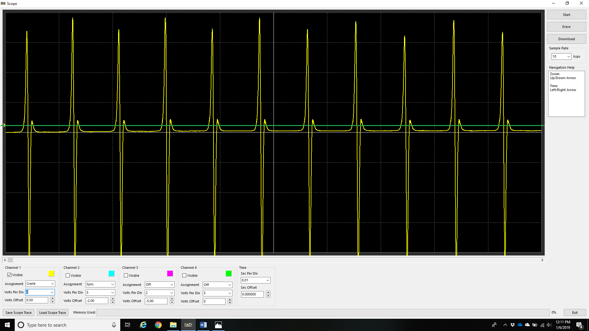
The above example shows a crankshaft trigger signal with the Crank Sensor Arming Threshold set too low (0.5 V), represented by the green line.
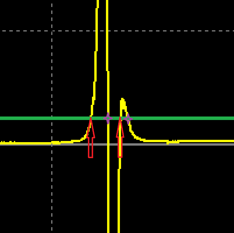
With the above example zoomed in, the trigger signal can be seen crossing the Arming Threshold (green line) twice, indicated by the red arrows. Each time the signal subsequently transitions through the zero-crossing point, the ECU detects a trigger event (purple markers). The first trigger event is the valid tooth, while the second is a false trigger caused by the Arming Threshold being set too low.
Increasing the Arming Threshold above the secondary signal oscillation prevents the input circuit from re-arming, eliminating the false trigger. In this example, increasing the Arming Threshold to approximately 3.0 V resolves the issue.