Crank Index and Sync Sensor
Overview
The Crank Index Sensor establishes the crankshaft position, while the Sync Sensor identifies the engine phase within the complete engine cycle. This allows the ECU to determine the exact engine position and correctly identify the individual cylinder events.
For example, a conventional four-stroke engine has a 720° engine cycle, while a rotary engine has a 360° engine cycle.
The sensor type, signal edge, and pull-up configurations can be set from this menu.
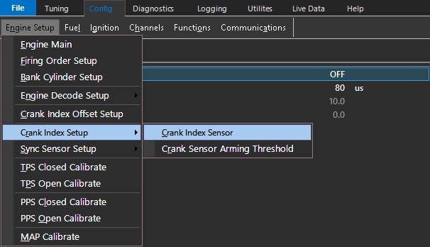
Sensor Type
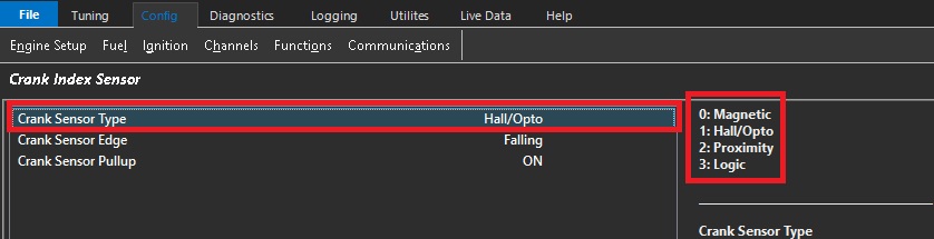
The Sensor Type setting defines the type of sensor connected to the selected Crank Index Sensor or Sync Sensor input.
| Value | Sensor Type |
|---|---|
| 0 | Magnetic |
| 1 | Hall Effect or Optical |
| 2 | Proximity |
| 3 | Logic (available in a future release) |
Magnetic
Magnetic sensors are voltage-generating sensors that produce a sinusoidal signal. The signal swings both positive and negative around 0V, with the signal amplitude generally increasing as engine speed increases. Magnetic sensors can typically be identified by having two signal wires.
Warning
Always use the dedicated positive and negative trigger inputs on the ECU for the Crank and Sync sensors. Do not connect the sensor ground to the engine block or chassis. The sensor(s) must be wired directly to the dedicated ECU trigger inputs.
Magnetic sensors must use shielded cable from the sensor through to the ECU input. Magnetic sensor signals are particularly susceptible to electrical interference, especially from radiated interference generated by the ignition system. Sensor wiring must be routed well away from ignition coils, ignition wiring, and other sources of electrical interference. The cable shield must be connected to the ECU Shield connection, correct wiring practices are therefore essential.
Magnetic sensor polarity must be correct. Incorrect polarity can result in poor or unstable engine decoding. See Using the Scope – Incorrect Crank/Sync Sensor Polarity for further information.
Hall Effect / Optical
Hall Effect and optical sensors produce a digital square-wave signal and require a power supply to operate. They can typically be identified by having three wires: supply, signal, and ground.
Emtron ECUs provide a dedicated 8V sensor supply to provide a regulated and clean power supply for these sensors.
Warning
- Always use the dedicated positive and negative trigger inputs on the ECU for the Crank and Sync sensors. DO NOT connect the sensor negative or ground to the engine block or chassis.** DO NOT connect Hall Effect ground (or any other “Pulsed” sensor grounds) to Analog Volt Ground pins. The sensor(s) must be wired directly to the dedicated ECU trigger inputs.
Sensor Edge
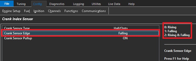
This setting defines which edge of the Crank Index or Sync Position sensor signal is used by the ECU for engine position and synchronisation.
| Value | Edge |
|---|---|
| 0 | Rising |
| 1 | Falling |
| 2 | Rising & Falling |
Sync Sensor Rising and Falling
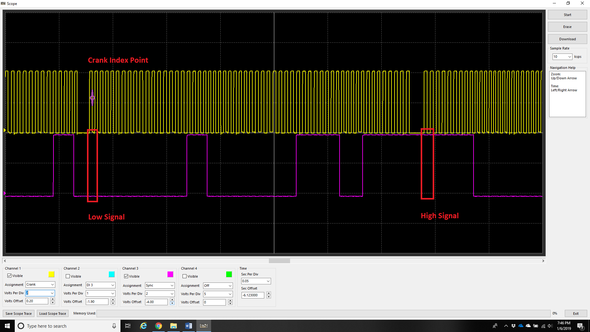
Engines with multi-tooth sync sensors will typically have a “long” tooth at the crank index point.
In this configuration, the Sync Sensor provides a different signal level for each half of the engine cycle:
For example in the above image:
- 0–360°: Sync signal is Low (Purple trace)
- 360–720°: Sync signal is High (Purple trace)
The ECU uses the Crank Index gap to establish the crankshaft position and the Sync signal level to immediately determine which 360° half of the engine cycle the crankshaft is in.
This means the ECU does not need to wait for an additional Sync edge to determine the engine position. As soon as the first crank index gap is detected, the ECU can determine the 720° engine position from the combination of the crank index position and the current Sync signal level.
For these trigger types, set the Sync Sensor Edge configuration to Rising and Falling.
Additional Information
For further information on multi-tooth sync sensors, Rising and Falling Edge configuration, or trigger decoding, contact Emtron Technical Support.
Custom Engine Decoding Modes
When using a custom decoding mode, such as 1 Tooth per TDC or Multi-Tooth Custom, Falling Edge should be used unless otherwise instructed by Emtron Support.
: Edge Selection Notes
Magnetic Sensors have the edge selection locked to Falling Edge. The ECU detects the positive to negative transition of the sensor signal and determines the trigger position from the zero-crossing point.
For Hall Effect Sensors, the Falling Edge is generally preferred as it provides the sharpest and most consistent signal transition. A faster signal transition allows the ECU to determine the engine position more accurately and reduces timing variation caused by slow or noisy signal transitions. This is particularly important for the Crank Index Sensor, where accurate and repeatable trigger position is critical.
For a Sync Position Sensor, the sensor is not normally used to determine the primary crankshaft position, so the exact edge transition and its slope are less critical. For this reason, the Rising Edge may also be used if required. For example, if the selected sync edge is too close to a crank decoding edge, the opposite edge can be selected to move the sync event further away from the crank decoding event and provide a more reliable sync position.
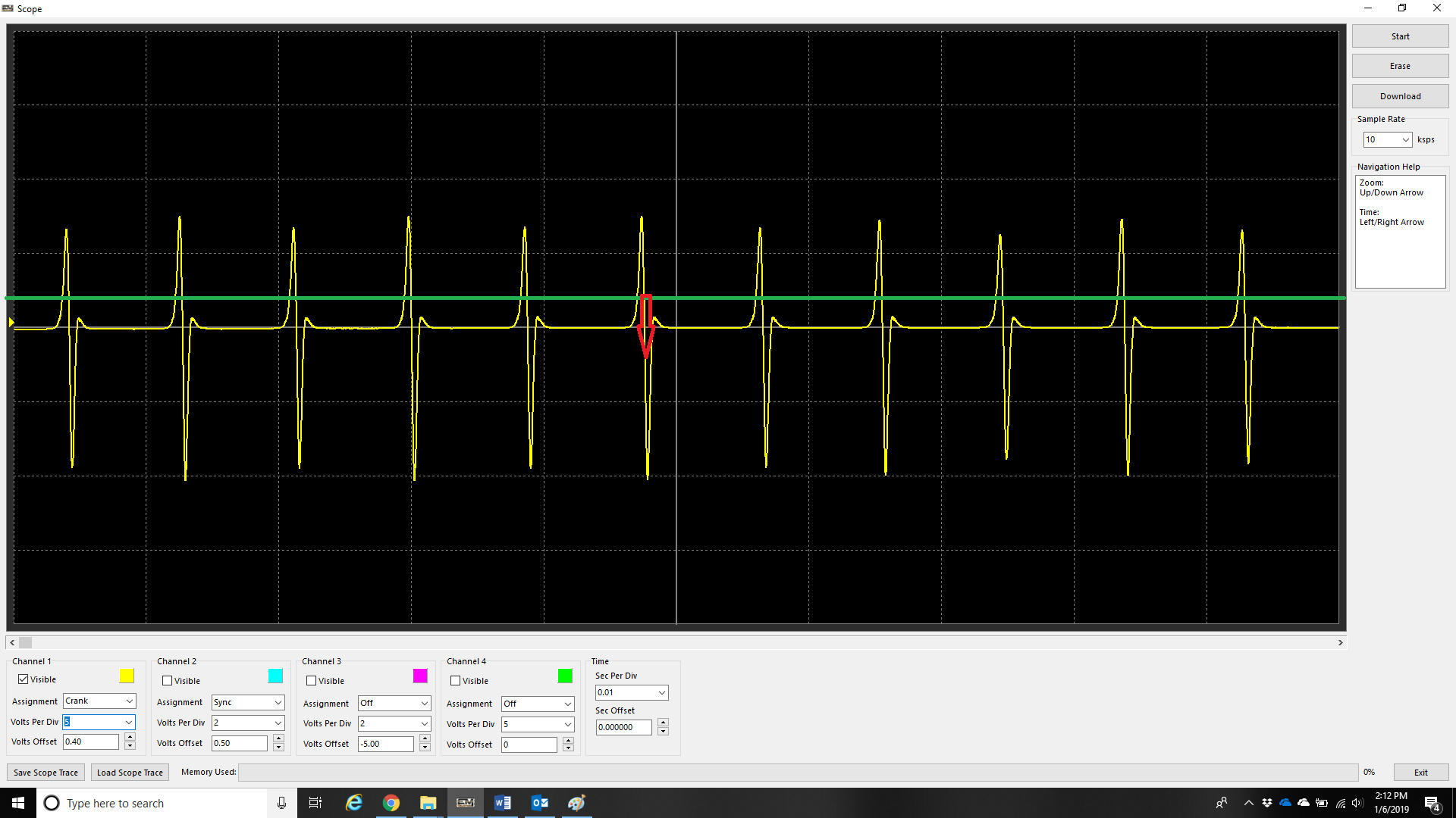
The example above illustrates the fast Falling Edge of a magnetic sensor signal
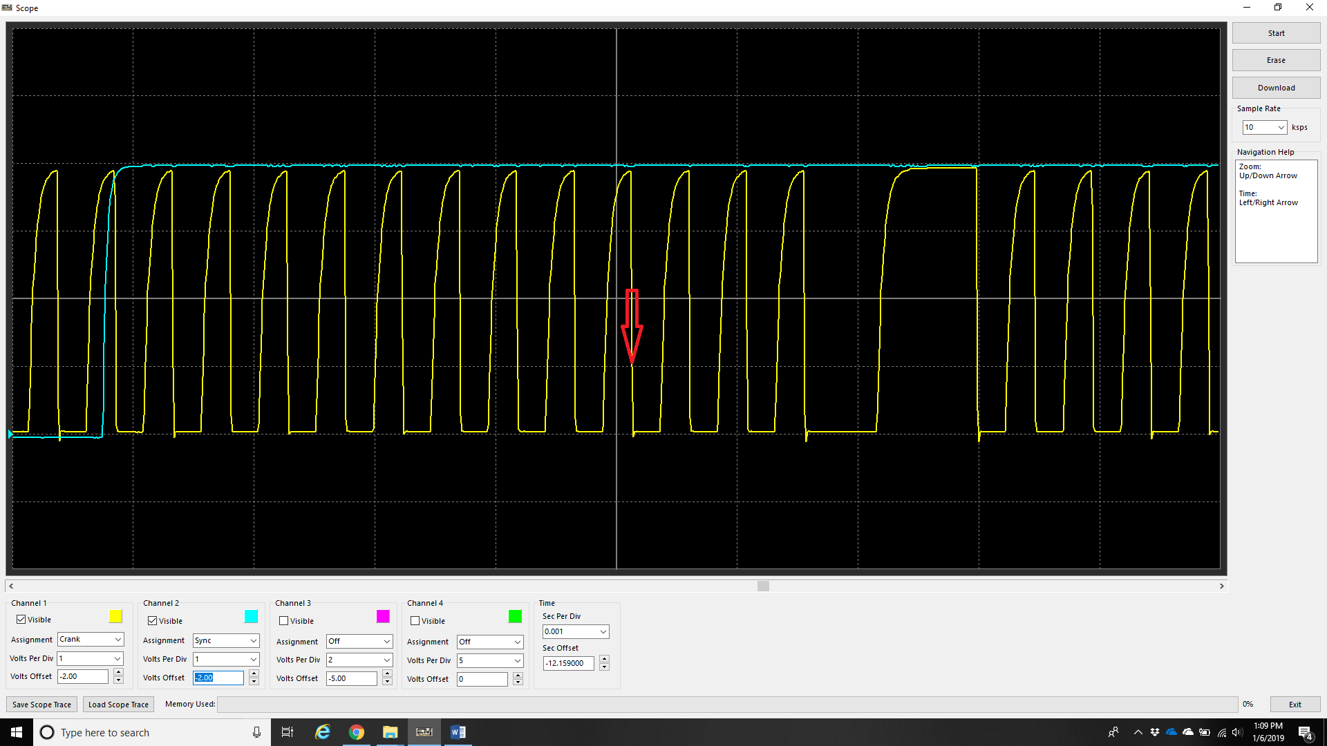
The example above illustrates the fast Falling Edge of a Hall Effect sensor signal.
Triggering from the Rising Edge in either of the two examples above will cause the engine timing to wander as RPM changes.
Sensor Pullup
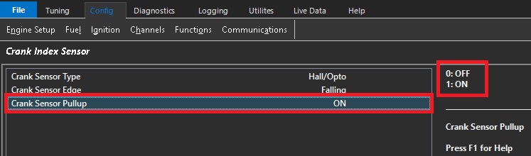
This setting controls the internal 5V pull-up used with Hall Effect, Optical, and Proximity Crank Sensors.
The pull-up is not available when using a Magnetic sensor.
| Value | Pull-Up |
|---|---|
| 0 | OFF |
| 1 | ON |
Sensor Arming Threshold
Arming thresholds for digital signals (including crank and sync sensors) describe the level in which the voltage level must go above before the signal can be valid. Regardless of signal (magnetic, or digital), the threshold voltage level must be reached before the signal can be considered valid.
** The threshold value does not mean this is the value in which the ECU “triggers”.
See Arming Threshold section for more information.

Typical Arming Threshold values for a Magnetic Sensor are shown in the image above. Note how the Arming Threshold increases as engine speed increases.
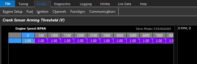
Typical Arming Threshold values for a Hall Effect Sensor are shown in the image above. For a standard 0–5V square-wave signal, it is recommended to set the Arming Threshold to a constant 2.0V across the entire table. This is approximately 40% of the sensor pull-up supply voltage.
Additional Information:
- Arming Threshold control is available for all trigger types.
- Use the Scope function within the Emtron to validate the voltage threshold to be used.
Pre-Defined Engine Decoding Modes
When using a Pre-Defined Engine Decoding Mode (3 or higher), the Crank/Sync Sensor Type, Edge Configuration, and Pull-Up Configuration are pre-configured for the selected decoding mode. These settings should not normally be changed.