Subsections of Triggers
Engine Decoding Mode
The Engine Decoding Mode selects the trigger pattern and decoding used by the ECU to determine engine position and synchronisation.
The selected mode determines how the ECU interprets the crankshaft and camshaft trigger signals, establishing the engine position used by the ECU for ignition timing, fuel injection timing and other engine position-dependent functions including Variable Valve Timing (VVT), knock control and torque control etc.
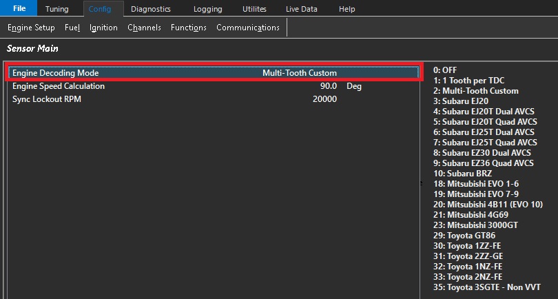
For predefined decoding modes (Option 3 and above), the ECU will initialize both the Crank Index and Sync Sensor channels to the correct settings. This includes:
- Sensor Type
- Sensor Edge
- Sensor Pull-up
- Arming Threshold Tables
This is considered Pre-Defined Decoding. All settings for Tooth Count, Index Tooth and Crank Index Offset are controlled by the ECU firmware and cannot be customized. However, the Edge Type, Pull-up, and Arming thresholds can all be adjusted after the new decoding mode has been selected.
The most common adjustment is configuring the Arming Threshold Tables when using magnetic (VR) sensors. As a general guideline, the arming thresholds should initially be set to approximately 60% of the peak sensor voltage.
Use the Emtron Scope function to measure the peak crankshaft and camshaft sensor signal voltages to configure the Arming Threshold Tables correctly. See here for more information: Setting Arming Threshols
The predefined decoder modes are intended for engines using the standard OEM trigger pattern. If your engine uses a modified or custom trigger arrangement based on one of these engines, select Multi-Tooth Custom where appropriate or contact Emtron Support for assistance configuring the trigger system.
Any setting change in the Crank Index or Sync Sensor menu that differ from the default values may cause permanent engine damage.
Modifying the automatically configured Crank Index or Sync Sensor settings for a predefined decoder may result in incorrect engine synchronisation and ignition timing. Incorrect Engine decoding configuration can prevent the engine from starting or, in severe cases, may result in engine damage.
– Engine Speed Calculation
This setting defines the number of crankshaft degrees over which engine speed is calculated. A wider measurement window provides greater averaging and a more stable engine speed calculation.
Typical values range from 1 TDC event (90° for an 8-cylinder engine, 180° for a 4-cylinder engine) up to 1/2 of an engine cycle (360°).
The maximum value is 2 engine cycles (1440°)
Sync Lockout RPM
The Sync Sensor input is ignored when engine speed is above this value.
This setting is primarily used to help diagnose engine decoding errors occurring at high engine speeds. For example, if an engine decoding error occurs at 6500 RPM, setting Sync Lockout RPM to 6000 RPM will cause the ECU to ignore the Sync Sensor above 6000 RPM.
If the decoding error no longer occurs, this indicates that the Sync Sensor or its associated signal may be the cause of the issue.
Setting this value to 20,000 RPM disables the Sync Lockout feature.
Arming Thresholds
Overview
The Arming Threshold defines the voltage level that the input signal must cross before the input circuit considers the signal valid. This applies regardless of signal type, including magnetic (VR) and digital inputs.
Magnetic (VR) Sensors
The Arming Threshold defines the voltage level that the input signal must exceed before the input circuit is armed and ready to detect a trigger event. Once armed, the input circuit waits for the signal to transition through the zero-crossing point from a positive voltage to a negative voltage.
NOTE: The Arming Threshold does not define the actual trigger point in this mode. It only determines when the input circuit is armed and ready to detect the subsequent zero-crossing event.
Hall Effect/ Digital Sensors
The Arming Threshold defines the voltage level that the input signal must cross before the trigger circuit is armed and ready to detect the selected trigger edge. Once the arming condition has been met, the trigger event occurs when the signal transitions through the configured Sensor Edge (rising or falling edge).
The correct Arming Threshold configuration ensures reliable trigger detection across the full engine operating range and helps prevent trigger errors, excessive error counts, misfires, or no-start conditions.
Additional Information
For Magnetic (VR) sensors, the required Arming Threshold typically increases with engine speed as the generated signal voltage increases. For this reason, the Arming Threshold should be configured using a table that increases with RPM to maintain reliable trigger detection across the full engine operating range. In most applications, the maximum Arming Threshold required for stable operation is typically no more than 8 V.
For Magnetic (VR) sensors, the required Arming Threshold naturally increases with engine speed as the sensor output voltage increases. This is a desirable characteristic, as the higher threshold also improves noise immunity by rejecting low-amplitude electrical interference while maintaining reliable trigger detection.
For Hall effect and other digital sensors, the signal voltage is normally independent of engine speed. As a result, the Arming Threshold typically remains constant across the full engine operating range.
The maximum configurable Arming Threshold is 12V.
The Emtron trigger inputs are designed to withstand signal amplitudes of up to ±100V.
Arming Threshold Setup
The Emtron Scope function should be used to setup the Arming Threshold Tables by measuring the peak sensor voltage across the engine operating range.
Magnetic (VR) Sensor Arming Threshold Setup
Configure the Arming Threshold to approximately 50% of the measured peak sensor voltage at each engine speed. This positions the threshold above ground noise while allowing sufficient margin for normal signal amplitude variation, improving trigger reliability.
In most applications, the maximum Arming Threshold required for reliable operation is approximately 8 V. If the peak sensor voltage exceeds 16 V, an Arming Threshold of 8 V is generally suitable.
Digital Sensor Arming Threshold Setup
For digital 0–5 V square-wave signals, configure the Arming Threshold to a fixed value of approximately 2.0 V across the entire engine operating range. This provides a stable switching point while maintaining adequate noise margin between the low and high signal levels.
Example:
The following example uses the Emtron Scope function to view the crankshaft sensor signal and identify a trigger signal integrity issue. The measured signal amplitude is then used to re-configure the Arming Threshold, resulting in reliable trigger detection.
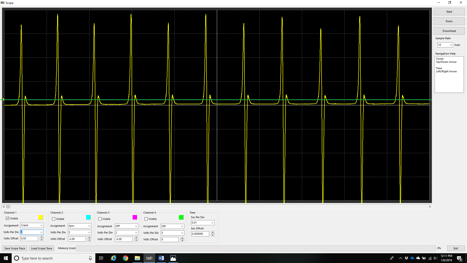
The above example shows a crankshaft trigger signal with the Crank Sensor Arming Threshold set too low (0.5 V), represented by the green line.
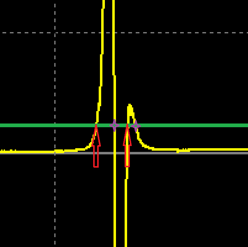
With the above example zoomed in, the trigger signal can be seen crossing the Arming Threshold (green line) twice, indicated by the red arrows. Each time the signal subsequently transitions through the zero-crossing point, the ECU detects a trigger event (purple markers). The first trigger event is the valid tooth, while the second is a false trigger caused by the Arming Threshold being set too low.
Increasing the Arming Threshold above the secondary signal oscillation prevents the input circuit from re-arming, eliminating the false trigger. In this example, increasing the Arming Threshold to approximately 3.0 V resolves the issue.
Crank Index Offset Setup
Overview
The Crank Index Offset Setup is one of the most critical configuration steps within the ECU.
The ECU determines engine position by detecting a known trigger event, commonly referred to as the Index Tooth. Since the Index Tooth position does not normally coincide with Top Dead Centre (TDC) Cylinder #1 Compression, the Crank Index Offset defines the angular relationship between these two events. This allows the ECU to accurately determine crankshaft position and maintain synchronisation with the engine.
Tuning Tips:
1) For Wasted Spark applications, always set the Ignition Lock Angle to 0.0° BTDC when verifying the Crank Index Offset.
Many timing lights calculate ignition advance using the measured ignition pulse frequency. Since wasted spark systems generate two ignition events per engine cycle, some timing lights may calculate an incorrect engine speed and display an incorrect ignition advance value. Using a lock angle of 0.0° BTDC allows the crankshaft TDC mark to be verified directly and eliminates this source of error.*
2) For Direct Fire ignition systems, the Ignition Lock Angle may be set to any convenient crankshaft timing mark available on the engine pulley.
3) The fuel injectors can be disabled to validate the initial Crank Index Offset value.prior to starting the engine. See Config -> Fuel -> Fuel Main -> Injection Mode -> Off.
4) Direct fire engines may be 360deg out of cycle which can be corrected numerically (i.e add or subtract 360 from the Crank Index value).
Ignition Timing Synchronisation
Before calibrating the ignition system, the ECU ignition timing must be synchronised with the actual engine crankshaft position.
Crank Index Offset Calibration
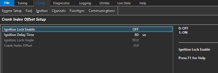
- Enable Ignition Lock and configure a fixed ignition timing value using the Ignition Lock Angle.
NOTE: When Ignition Lock Enable is ON, Ignition Lock Angle value overrides all other timing values in ECU. - Start the engine and use a timing light to measure the actual ignition timing.
- Compare the measured ignition timing with the configured Ignition Lock Angle.
- Adjust the Crank Index Offset until the timing light reading matches the configured Ignition Lock Angle.
This procedure should be performed with the engine operating at idle speed.
Ignition Delay Time Calibration
Once the Crank Index Offset has been calibrated at idle, ignition timing should be verified over the engine operating range.
As engine speed increases, ignition coil turn-on delays, ignition module propagation delays and ECU output delays can introduce small timing errors.
The Ignition Delay Time parameter compensates for these delays to ensure the commanded ignition timing accurately matches the actual crankshaft position across the complete engine speed range.
Adjustment guidelines:
- If the measured ignition timing retards as engine speed increases, increase the Ignition Delay Time value.
- If the measured ignition timing advances as engine speed increases, decrease the Ignition Delay Time value.
Once correctly calibrated, the timing light should indicate a constant ignition timing value regardless of engine speed when Ignition Lock is enabled.
Important:
The Crank Index Offset and Ignition Delay Time should always be verified regardless of trigger presets or predefined trigger configurations.
Incorrect calibration will result in the ECU commanding ignition timing that does not match the actual crankshaft position, potentially causing poor engine performance or engine damage.
Crank Index and Sync Sensor
Overview
The Crank Index Sensor establishes the crankshaft position, while the Sync Sensor identifies the engine phase within the complete engine cycle. This allows the ECU to determine the exact engine position and correctly identify the individual cylinder events.
For example, a conventional four-stroke engine has a 720° engine cycle, while a rotary engine has a 360° engine cycle.
The sensor type, signal edge, and pull-up configurations can be set from this menu.
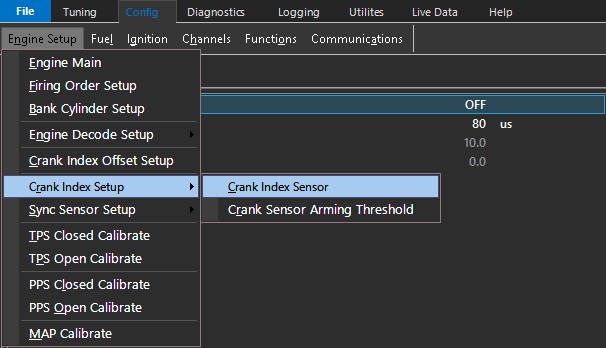
Sensor Type
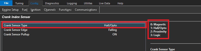
The Sensor Type setting defines the type of sensor connected to the selected Crank Index Sensor or Sync Sensor input.
| Value | Sensor Type |
|---|---|
| 0 | Magnetic |
| 1 | Hall Effect or Optical |
| 2 | Proximity |
| 3 | Logic (available in a future release) |
Magnetic
Magnetic sensors are voltage-generating sensors that produce a sinusoidal signal. The signal swings both positive and negative around 0V, with the signal amplitude generally increasing as engine speed increases. Magnetic sensors can typically be identified by having two signal wires.
Warning
Always use the dedicated positive and negative trigger inputs on the ECU for the Crank and Sync sensors. Do not connect the sensor ground to the engine block or chassis. The sensor(s) must be wired directly to the dedicated ECU trigger inputs.
Magnetic sensors must use shielded cable from the sensor through to the ECU input. Magnetic sensor signals are particularly susceptible to electrical interference, especially from radiated interference generated by the ignition system. Sensor wiring must be routed well away from ignition coils, ignition wiring, and other sources of electrical interference. The cable shield must be connected to the ECU Shield connection, correct wiring practices are therefore essential.
Magnetic sensor polarity must be correct. Incorrect polarity can result in poor or unstable engine decoding. See Using the Scope – Incorrect Crank/Sync Sensor Polarity for further information.
Hall Effect / Optical
Hall Effect and optical sensors produce a digital square-wave signal and require a power supply to operate. They can typically be identified by having three wires: supply, signal, and ground.
Emtron ECUs provide a dedicated 8V sensor supply to provide a regulated and clean power supply for these sensors.
Warning
- Always use the dedicated positive and negative trigger inputs on the ECU for the Crank and Sync sensors. DO NOT connect the sensor negative or ground to the engine block or chassis.** DO NOT connect Hall Effect ground (or any other “Pulsed” sensor grounds) to Analog Volt Ground pins. The sensor(s) must be wired directly to the dedicated ECU trigger inputs.
Sensor Edge
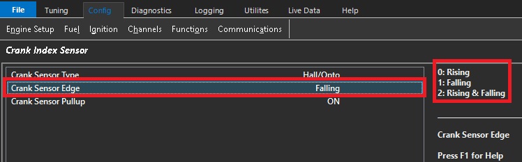
This setting defines which edge of the Crank Index or Sync Position sensor signal is used by the ECU for engine position and synchronisation.
| Value | Edge |
|---|---|
| 0 | Rising |
| 1 | Falling |
| 2 | Rising & Falling |
Sync Sensor Rising and Falling
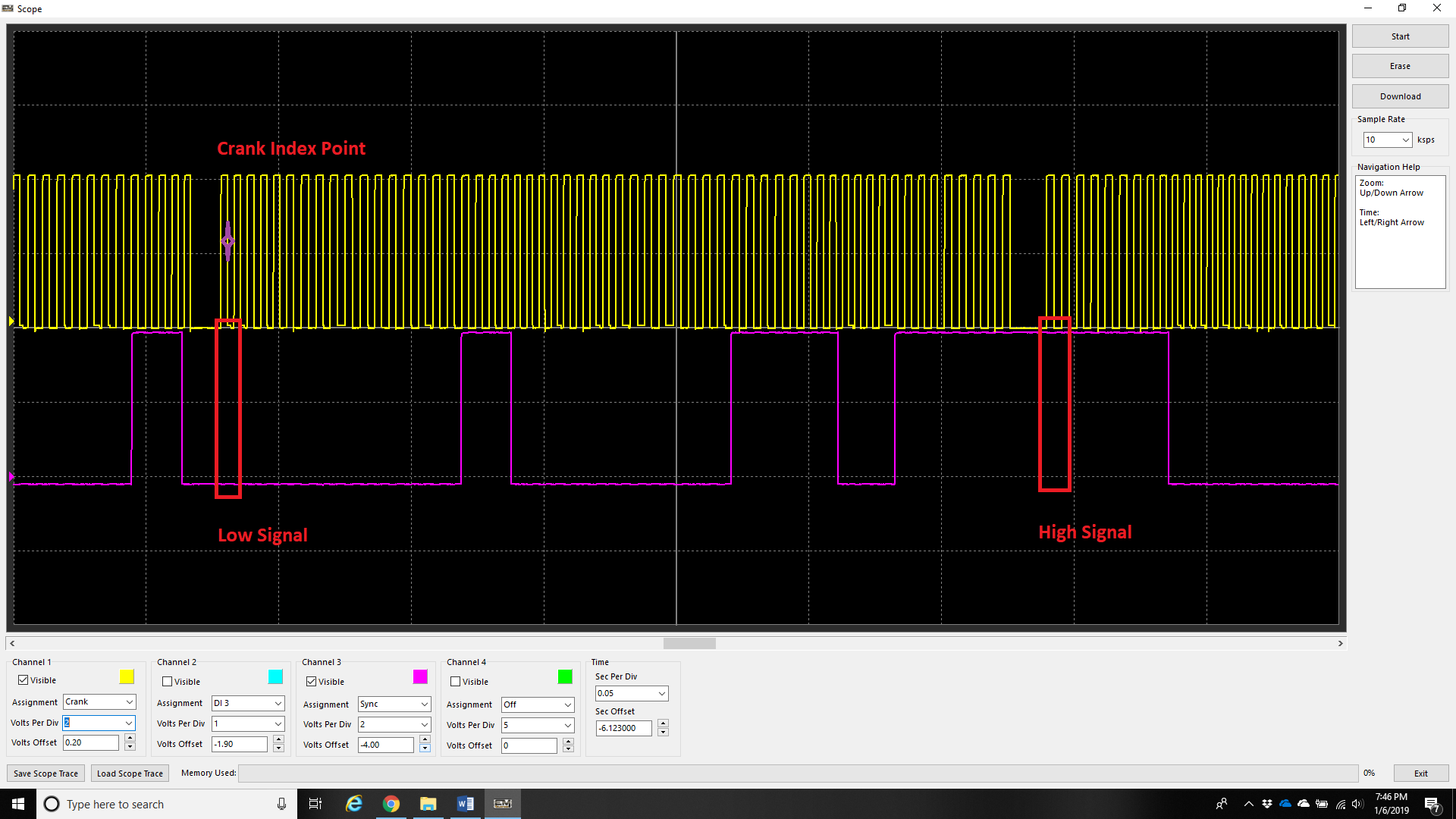
Engines with multi-tooth sync sensors will typically have a “long” tooth at the crank index point.
In this configuration, the Sync Sensor provides a different signal level for each half of the engine cycle:
For example in the above image:
- 0–360°: Sync signal is Low (Purple trace)
- 360–720°: Sync signal is High (Purple trace)
The ECU uses the Crank Index gap to establish the crankshaft position and the Sync signal level to immediately determine which 360° half of the engine cycle the crankshaft is in.
This means the ECU does not need to wait for an additional Sync edge to determine the engine position. As soon as the first crank index gap is detected, the ECU can determine the 720° engine position from the combination of the crank index position and the current Sync signal level.
For these trigger types, set the Sync Sensor Edge configuration to Rising and Falling.
Additional Information
For further information on multi-tooth sync sensors, Rising and Falling Edge configuration, or trigger decoding, contact Emtron Technical Support.
Custom Engine Decoding Modes
When using a custom decoding mode, such as 1 Tooth per TDC or Multi-Tooth Custom, Falling Edge should be used unless otherwise instructed by Emtron Support.
: Edge Selection Notes
Magnetic Sensors have the edge selection locked to Falling Edge. The ECU detects the positive to negative transition of the sensor signal and determines the trigger position from the zero-crossing point.
For Hall Effect Sensors, the Falling Edge is generally preferred as it provides the sharpest and most consistent signal transition. A faster signal transition allows the ECU to determine the engine position more accurately and reduces timing variation caused by slow or noisy signal transitions. This is particularly important for the Crank Index Sensor, where accurate and repeatable trigger position is critical.
For a Sync Position Sensor, the sensor is not normally used to determine the primary crankshaft position, so the exact edge transition and its slope are less critical. For this reason, the Rising Edge may also be used if required. For example, if the selected sync edge is too close to a crank decoding edge, the opposite edge can be selected to move the sync event further away from the crank decoding event and provide a more reliable sync position.
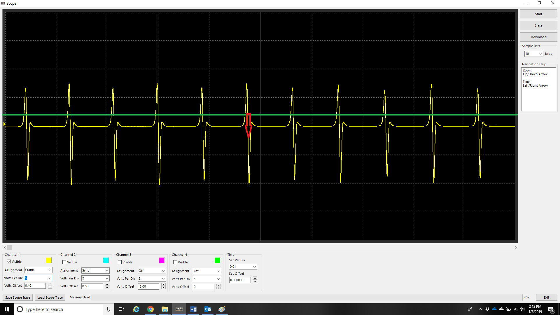
The example above illustrates the fast Falling Edge of a magnetic sensor signal
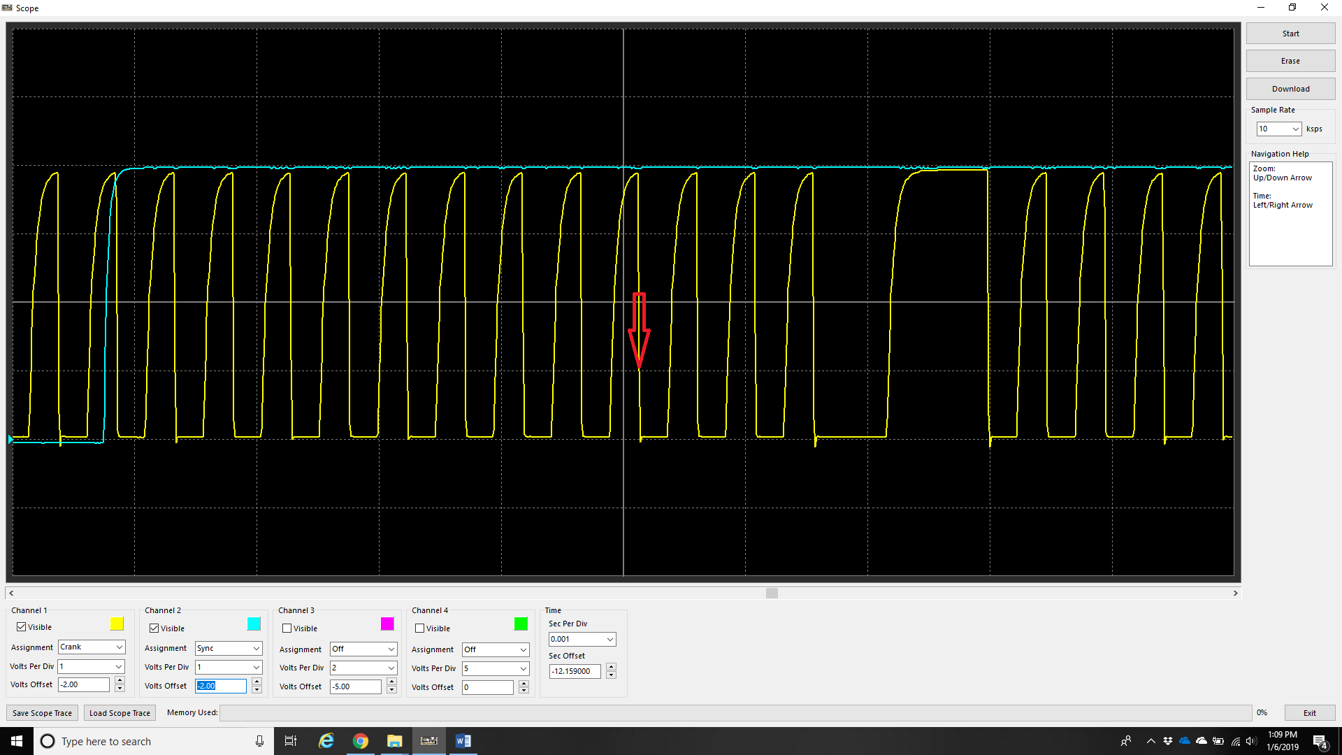
The example above illustrates the fast Falling Edge of a Hall Effect sensor signal.
Triggering from the Rising Edge in either of the two examples above will cause the engine timing to wander as RPM changes.
Sensor Pullup
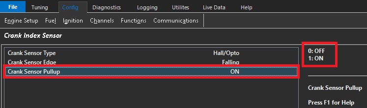
This setting controls the internal 5V pull-up used with Hall Effect, Optical, and Proximity Crank Sensors.
The pull-up is not available when using a Magnetic sensor.
| Value | Pull-Up |
|---|---|
| 0 | OFF |
| 1 | ON |
Sensor Arming Threshold
Arming thresholds for digital signals (including crank and sync sensors) describe the level in which the voltage level must go above before the signal can be valid. Regardless of signal (magnetic, or digital), the threshold voltage level must be reached before the signal can be considered valid.
** The threshold value does not mean this is the value in which the ECU “triggers”.
See Arming Threshold section for more information.

Typical Arming Threshold values for a Magnetic Sensor are shown in the image above. Note how the Arming Threshold increases as engine speed increases.
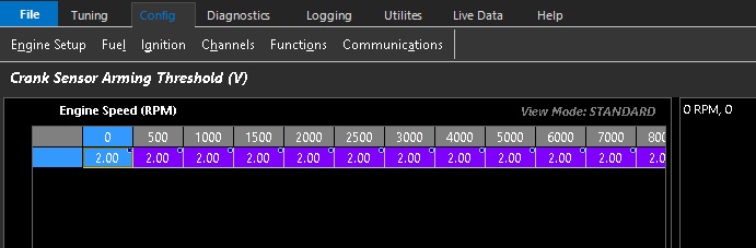
Typical Arming Threshold values for a Hall Effect Sensor are shown in the image above. For a standard 0–5V square-wave signal, it is recommended to set the Arming Threshold to a constant 2.0V across the entire table. This is approximately 40% of the sensor pull-up supply voltage.
Additional Information:
- Arming Threshold control is available for all trigger types.
- Use the Scope function within the Emtron to validate the voltage threshold to be used.
Pre-Defined Engine Decoding Modes
When using a Pre-Defined Engine Decoding Mode (3 or higher), the Crank/Sync Sensor Type, Edge Configuration, and Pull-Up Configuration are pre-configured for the selected decoding mode. These settings should not normally be changed.
Multi Tooth Setup
Multi Tooth Setup
This allows the user to define a Custom decoding mode for the ECU to use. In order for the ECU to synchronize timing of the engine, an “index tooth” position must be identified. :
The following settings are configured in this menu item :
Crank Tooth Count. See Crank Tooth Count for more information.
Missing Tooth Count. See Missing Tooth Count for more information.
Crank Index Position. See Crank Index Position for more information.
Sync Position Sensor. See Sync Sensor Position for more information.
Gap Detection Method. SeeGap Detection Method for more information.
When using a Custom Decoding mode, it is important to understand how and where the “index tooth” is identified, especially if the engine has adjustable triggers (mechanically).
On Non-Missing tooth Crank Triggers, there must be a sync sensor so the ECU can identify the “Index Tooth”
The Sync Sensor must be Camshaft driven if sequential fuel injection/direct fire ignition modes are being used
Missing Tooth Triggers do not require a sync sensor to identify the “Index Tooth”
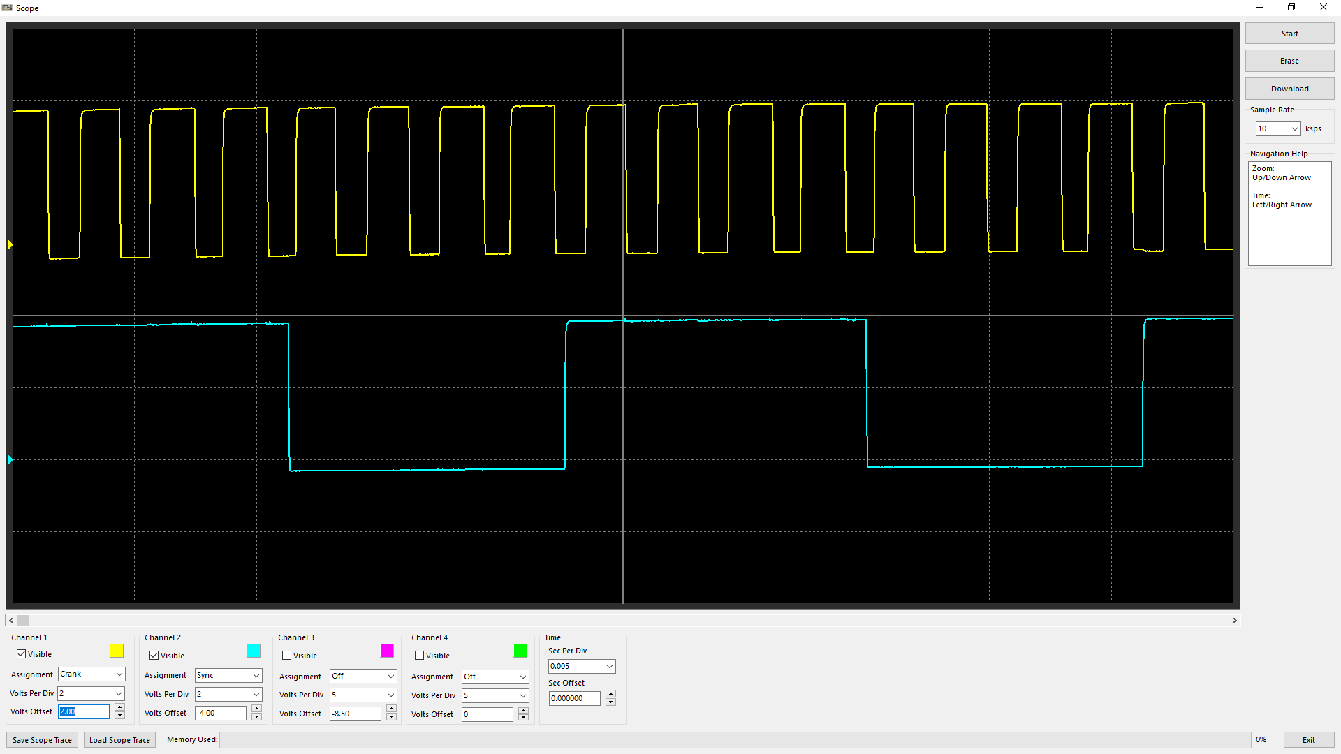
An example of a 4 Tooth Crank Wheel with a single tooth (50/50) Sync Sensor driven off a Camshaft (both Hall sensors)
Also known as 1-Tooth per TDC
** Note - This trigger could also be an example of a Crank Trigger being driven off of a Distributor (8 teeth), and therefore Camshaft driven
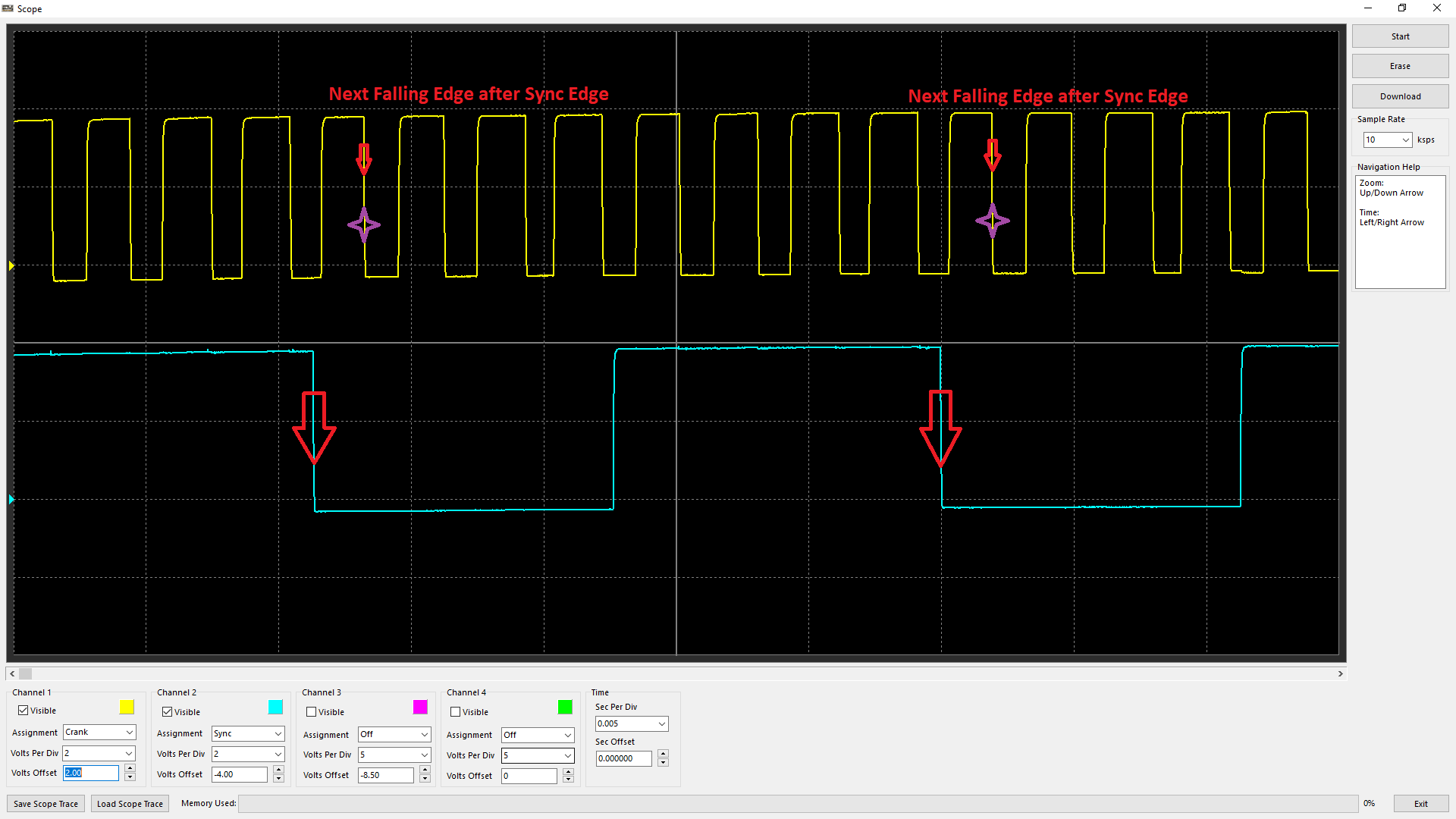
In this case, Edge configuration being set to both Falling Edge (see Crank Index/Sync Sensor Setup), the “Index Tooth” is identified as above
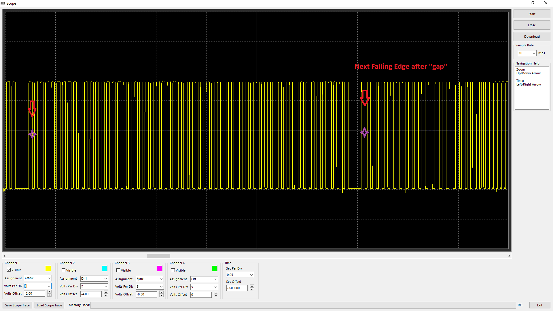
With a Missing Tooth crank trigger, the “Index Tooth” is recognized by the next Falling Edge after the gap position.
** Note - no Sync Sensor is even shown
** When using Magnetic Triggers, with incorrect polarity the ECU will not be able to recognize the gap and/or the “Index Tooth” position correctly. See Scope - Uses of Scope - Improper Crank/Sync Sensor Polarity
Sync Position %
Sync position refers to the point in which the ECU is identifying the Sync Edge location. This reference point can be critical as if there is any discrepancy to this position mechanically (wandering between the crank and cam trigger due to slack in cam belt/chain), it can cause crank/sync errors, engine cycle change, or even the firing order to change (especially in the case of non-missing crank trigger setup).
Emtron calculates the following channel for monitoring, diagnosis, and logging purposes - Sync Position %
The Sync Position % is calculated by factoring the position of the Sync Edge between consecutive Crank Teeth.
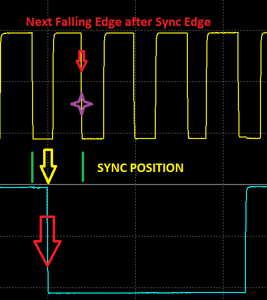
Looking at falling edges, the distance between crank teeth can be identified by the green lines, and the sync edge is identified by the yellow arrow. The value would be Sync Position % - 33% approximately in this case.
Best practice is to aim for a Sync Position % - 50%.
** Note - The higher the crank tooth count, the less resolution this runtime generally will have. IE a 60-2 trigger will have a much more unstable Sync Position % value vs a 1-Tooth Per TDC
Sync Position %
Sync Position %
Sync Position refers to the point at which the ECU identifies the Sync Edge location. This reference point is critical, as any mechanical variation between the crank and cam trigger positions, such as timing belt or chain slack, can cause the Sync Position to move.
Variations in the Sync Position can result in crank/sync errors, changes in the detected engine cycle, or even an incorrect firing order, particularly when using a non-missing crank trigger setup.
Emtron calculates the following channel for monitoring, diagnosis, and logging purposes - Sync Position %
The Sync Position % is calculated by factoring the position of the Sync Edge between consecutive Crank Teeth.
Looking at falling edges, the distance between crank teeth can be identified by the green lines, and the sync edge is identified by the yellow arrow. The value would be Sync Position % - 33% approximately in this case.
Best practice is to aim for a Sync Position % value of 50%.
NOTE: The higher the crank tooth count, the less resolution this runtime generally will have. IE a 60-2 trigger will have a much more unstable Sync Position % value vs a 1-Tooth Per TDC
Trouble Shooting
Improper Crank/Sync Sensor Polarity
During most start up support, we often encounter reversed polarity of crank/sync sensors. The Scope can be used to easily identify the issues. These polarity situations are especially sensitive when using missing tooth triggers due to the gap position affecting the index tooth position (see Crank Index Position), or not being able to be recognized at all.
When the trigger tooth passes the sensor, the magnetic sensor should produce a positive voltage before dropping voltage negative.

This is easier to identify on a trigger wheel with a lower tooth count as you can see above.
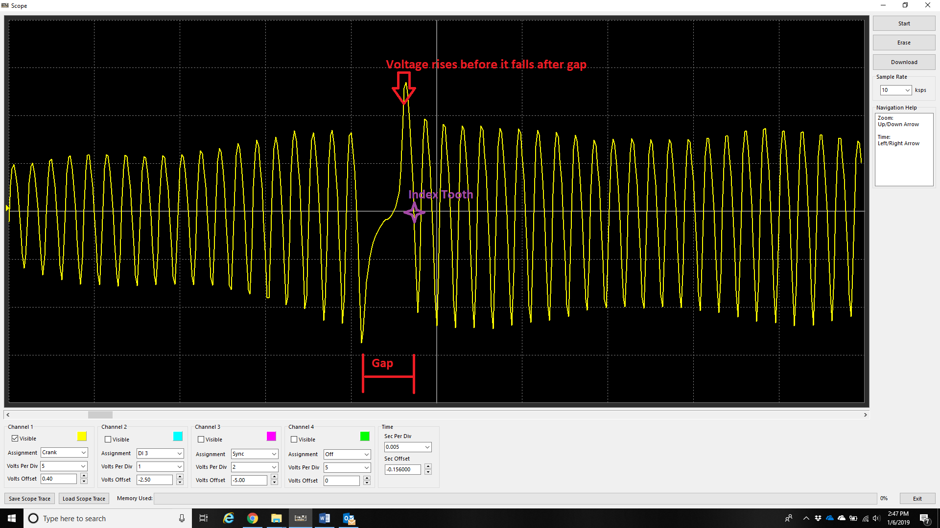
On a trigger wheel with multi tooth, it is more difficult to identify polarity.
For multi-tooth wheels with a missing tooth –
Use the gap to identify the polarity of this crank sensor is correct. Do this by ensuring that the next tooth after the gap rises before it falls.
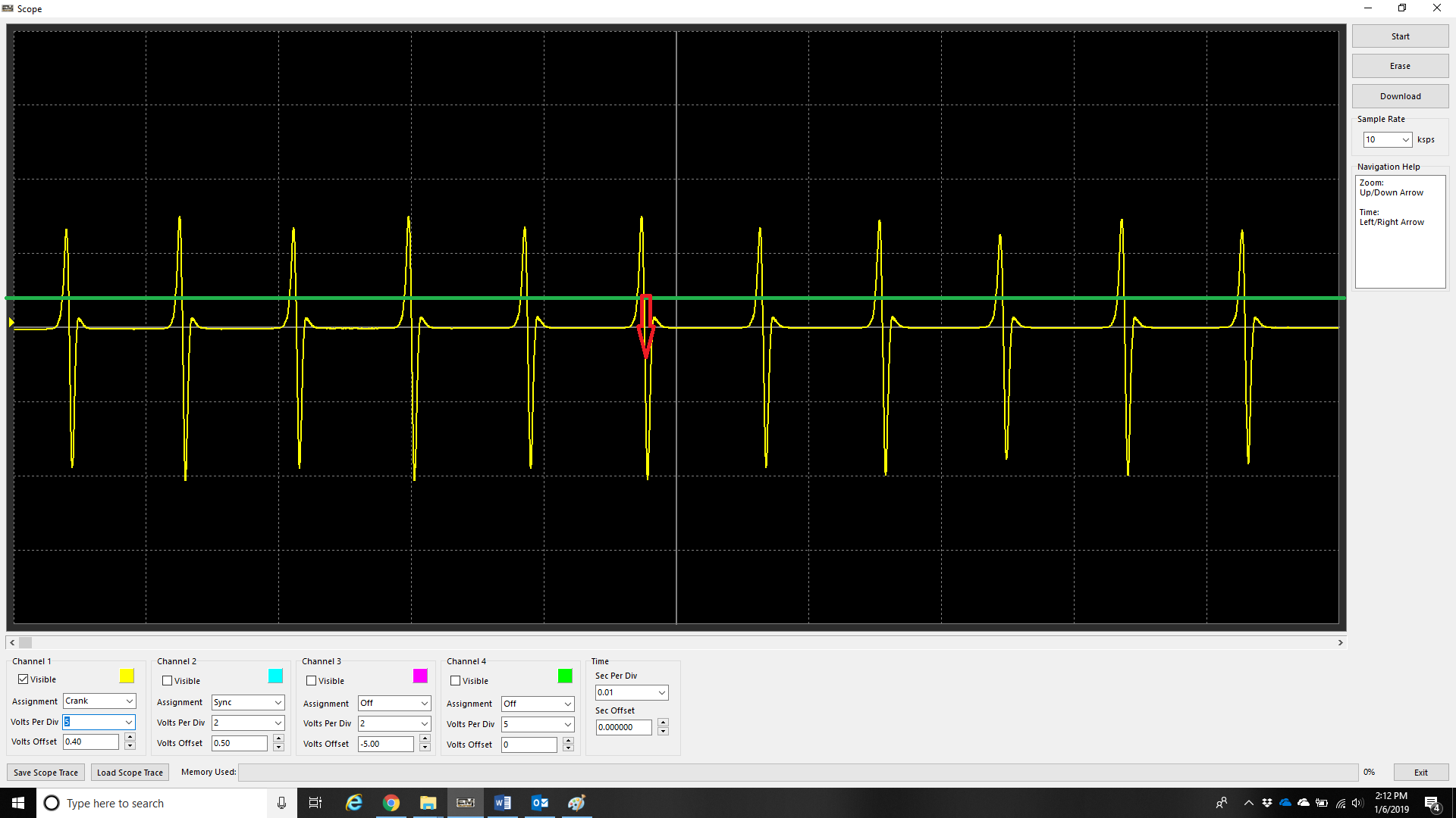
On a non-missing tooth multi-tooth trigger, the polarity can be validated generally by observing the “fast edge” being the falling edge. The above example shows this where the rising slope of the trace is much slower than the falling slope of the trace. The rising slope also will change based on the speed of the trigger wheel.
** Note – this is also why the falling edge provides most stable timing on magnetic triggers (with correct polarity).
** See Crank Index/Sync Sensor Setup
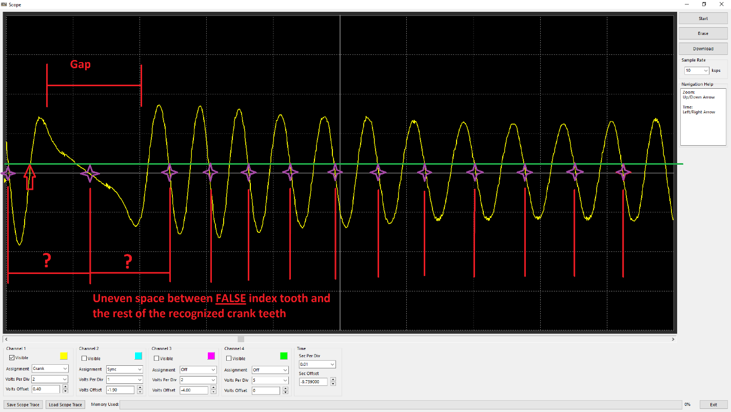
Crank trigger wired with incorrect polarity. Observe the voltage drops as the tooth after the gap approaches instead of rises.
In the case of missing tooth trigger wired with backwards polarity, the index tooth would either be recognized in the wrong position (earlier/before the index tooth has passed), or the “gap” not recognized properly due to not being able to differentiate a clear space. Subsequently this does not allow the ECU to identify the index tooth for timing the engine. Additionally, the uneven spacing (besides the expected “gap tooth number”) will cause the ECU to count crank tooth errors. The gap between the “false” index tooth position/gap and evenly spaced teeth will change with RPM as well.
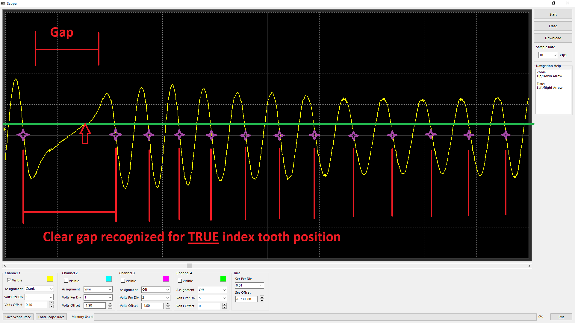
Crank trigger wired with correct polarity. Observe the voltage rises as the tooth after the gap approaches.
With the polarity correct, it is clear the gap can be recognized, and the index tooth is being appropriately recognized at the true position (tooth after the gap).
Improper Edge Configuration for Crank/Sync Sensor
Falling Edge
With correct sensor polarity, both magnetic and hall sensors should have falling edge polarity in most cases. This is because these sensors have consistent “fast” performance when the tone ring teeth pass the sensors.
An example of a magnetic sensors fast edge being the falling.
An example of a hall senor fast edge being the falling. Most hall sensors produce a very good “square” wave, so the point can be argued that rising edge can be used, however at higher revs some will produce this “saw tooth” pattern which means triggering that way will cause timing to wander.
Rising and Falling Edge Sync Mode
Engines with multi-tooth sync sensors usually will have a “long” tooth during the “crank index point”. Normally, a custom decoding mode is needed to run the engine with multiple sync teeth, but in this case because there is a clear difference in signal on the sync input on each stroke (low vs high), the ECU can determine the stroke immediately (this is the fastest way to decode starting/720 sync). Set Sync Sensor Edge configuration to Rising and Falling for these trigger types.
** See Sync Sensor Setup – Sync Sensor