Engine Decoding Mode
The Engine Decoding Mode selects the trigger pattern and decoding used by the ECU to determine engine position and synchronisation.
The selected mode determines how the ECU interprets the crankshaft and camshaft trigger signals, establishing the engine position used by the ECU for ignition timing, fuel injection timing and other engine position-dependent functions including Variable Valve Timing (VVT), knock control and torque control etc.
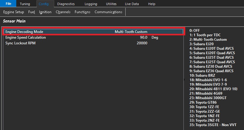
For predefined decoding modes (Option 3 and above), the ECU will initialize both the Crank Index and Sync Sensor channels to the correct settings. This includes:
- Sensor Type
- Sensor Edge
- Sensor Pull-up
- Arming Threshold Tables
This is considered Pre-Defined Decoding. All settings for Tooth Count, Index Tooth and Crank Index Offset are controlled by the ECU firmware and cannot be customized. However, the Edge Type, Pull-up, and Arming thresholds can all be adjusted after the new decoding mode has been selected.
The most common adjustment is configuring the Arming Threshold Tables when using magnetic (VR) sensors. As a general guideline, the arming thresholds should initially be set to approximately 60% of the peak sensor voltage.
Use the Emtron Scope function to measure the peak crankshaft and camshaft sensor signal voltages to configure the Arming Threshold Tables correctly. See here for more information: Setting Arming Threshols
The predefined decoder modes are intended for engines using the standard OEM trigger pattern. If your engine uses a modified or custom trigger arrangement based on one of these engines, select Multi-Tooth Custom where appropriate or contact Emtron Support for assistance configuring the trigger system.
Any setting change in the Crank Index or Sync Sensor menu that differ from the default values may cause permanent engine damage.
Modifying the automatically configured Crank Index or Sync Sensor settings for a predefined decoder may result in incorrect engine synchronisation and ignition timing. Incorrect Engine decoding configuration can prevent the engine from starting or, in severe cases, may result in engine damage.
– Engine Speed Calculation
This setting defines the number of crankshaft degrees over which engine speed is calculated. A wider measurement window provides greater averaging and a more stable engine speed calculation.
Typical values range from 1 TDC event (90° for an 8-cylinder engine, 180° for a 4-cylinder engine) up to 1/2 of an engine cycle (360°).
The maximum value is 2 engine cycles (1440°)
Sync Lockout RPM
The Sync Sensor input is ignored when engine speed is above this value.
This setting is primarily used to help diagnose engine decoding errors occurring at high engine speeds. For example, if an engine decoding error occurs at 6500 RPM, setting Sync Lockout RPM to 6000 RPM will cause the ECU to ignore the Sync Sensor above 6000 RPM.
If the decoding error no longer occurs, this indicates that the Sync Sensor or its associated signal may be the cause of the issue.
Setting this value to 20,000 RPM disables the Sync Lockout feature.