Trouble Shooting
Improper Crank/Sync Sensor Polarity
During most start up support, we often encounter reversed polarity of crank/sync sensors. The Scope can be used to easily identify the issues. These polarity situations are especially sensitive when using missing tooth triggers due to the gap position affecting the index tooth position (see Crank Index Position), or not being able to be recognized at all.
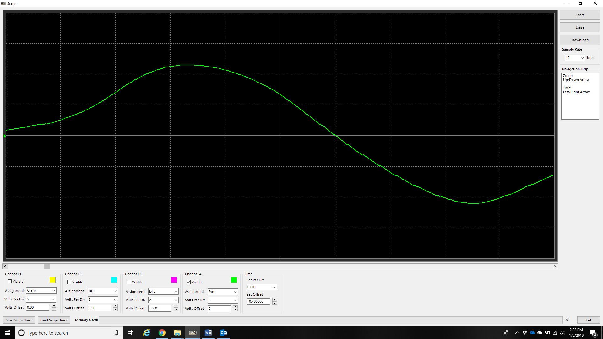
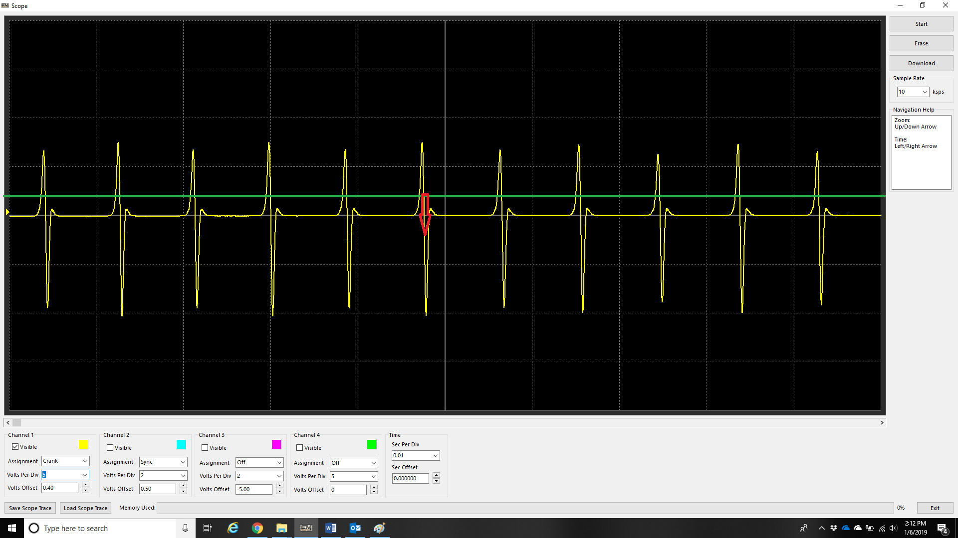
When the trigger tooth passes the sensor, the magnetic sensor should produce a positive voltage before dropping voltage negative.
This is easier to identify on a trigger wheel with a lower tooth count as you can see above.
On a trigger wheel with multi tooth, it is more difficult to identify polarity.
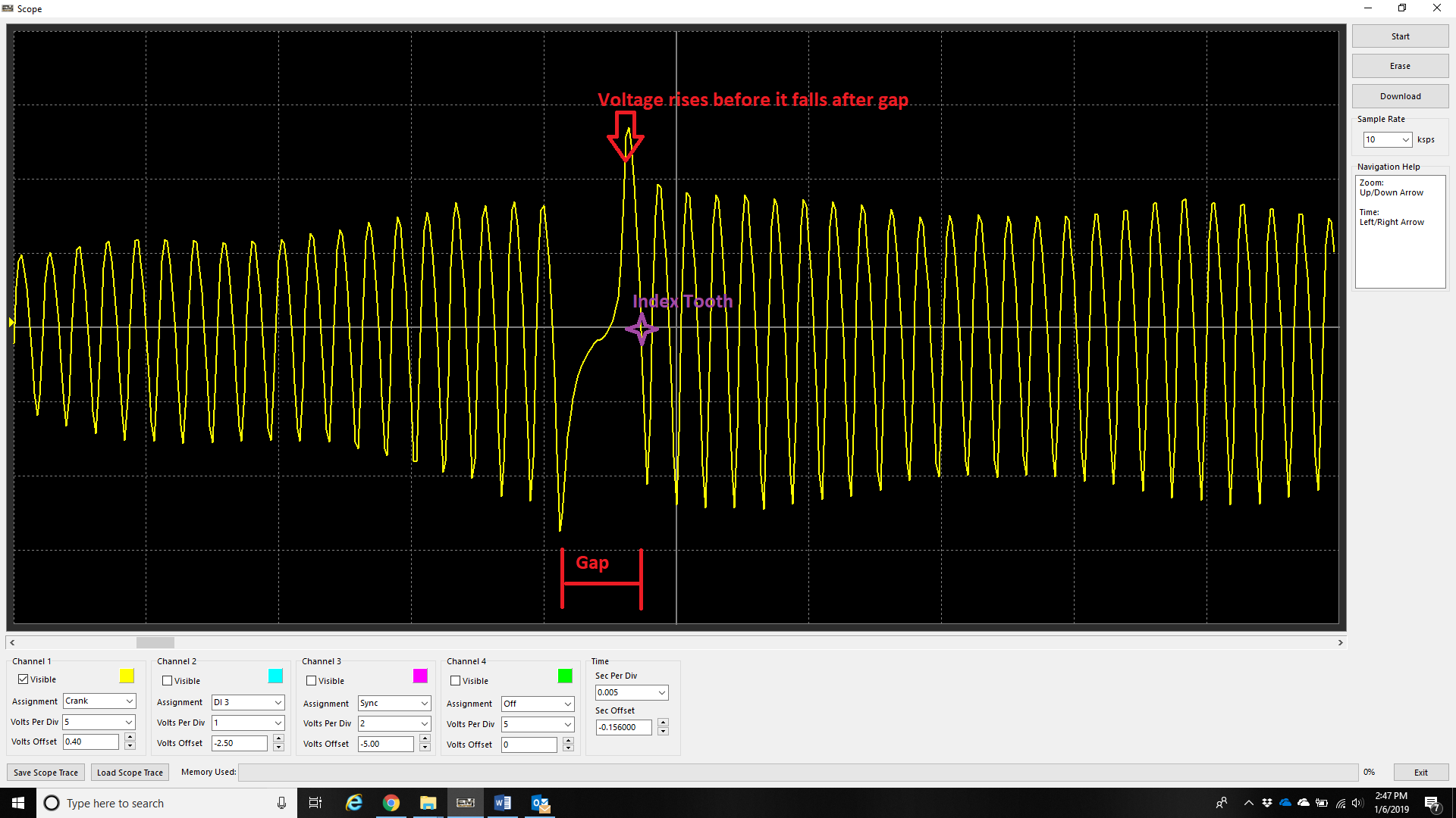
For multi-tooth wheels with a missing tooth –
Use the gap to identify the polarity of this crank sensor is correct. Do this by ensuring that the next tooth after the gap rises before it falls.

On a non-missing tooth multi-tooth trigger, the polarity can be validated generally by observing the “fast edge” being the falling edge. The above example shows this where the rising slope of the trace is much slower than the falling slope of the trace. The rising slope also will change based on the speed of the trigger wheel.
** Note – this is also why the falling edge provides most stable timing on magnetic triggers (with correct polarity).
** See Crank Index/Sync Sensor Setup
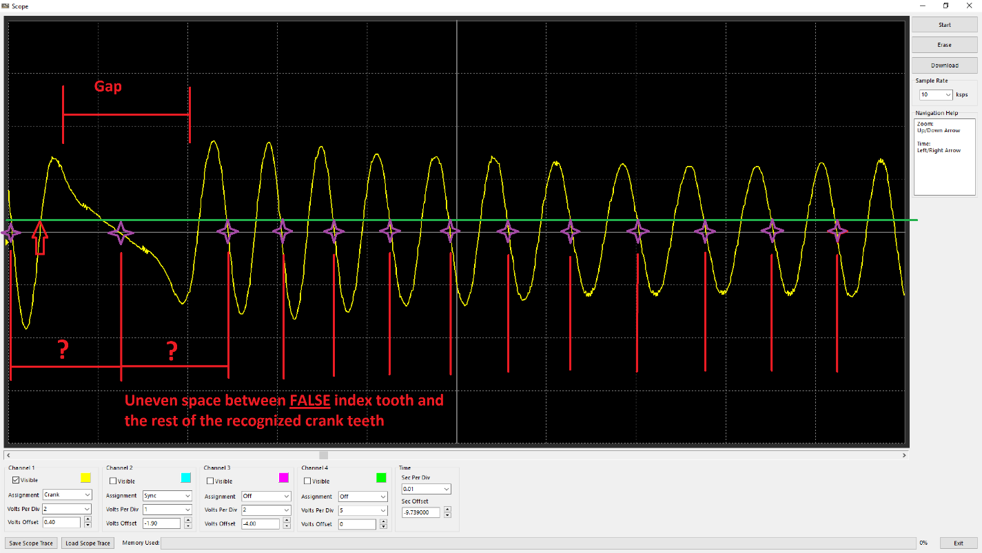
Crank trigger wired with incorrect polarity. Observe the voltage drops as the tooth after the gap approaches instead of rises.
In the case of missing tooth trigger wired with backwards polarity, the index tooth would either be recognized in the wrong position (earlier/before the index tooth has passed), or the “gap” not recognized properly due to not being able to differentiate a clear space. Subsequently this does not allow the ECU to identify the index tooth for timing the engine. Additionally, the uneven spacing (besides the expected “gap tooth number”) will cause the ECU to count crank tooth errors. The gap between the “false” index tooth position/gap and evenly spaced teeth will change with RPM as well.
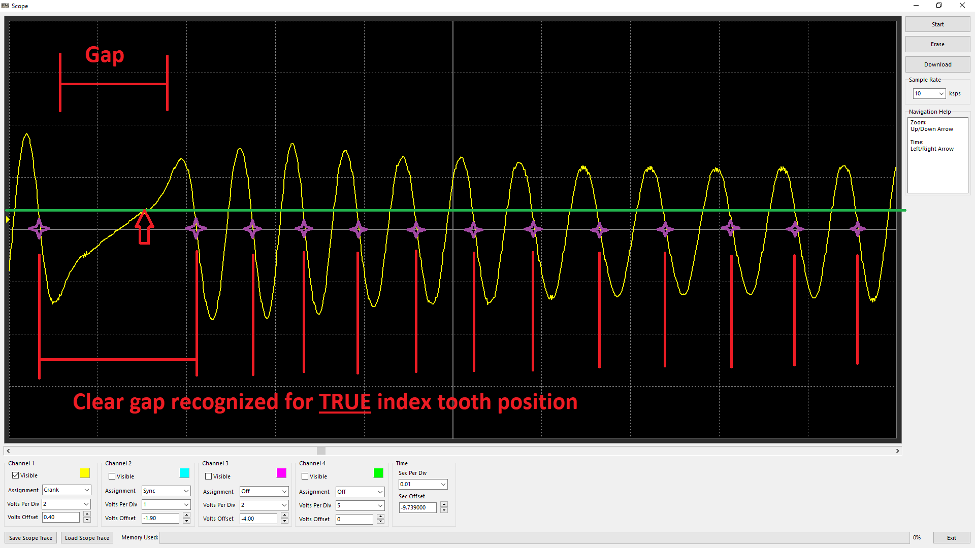
Crank trigger wired with correct polarity. Observe the voltage rises as the tooth after the gap approaches.
With the polarity correct, it is clear the gap can be recognized, and the index tooth is being appropriately recognized at the true position (tooth after the gap).
Improper Edge Configuration for Crank/Sync Sensor
Falling Edge
With correct sensor polarity, both magnetic and hall sensors should have falling edge polarity in most cases. This is because these sensors have consistent “fast” performance when the tone ring teeth pass the sensors.
An example of a magnetic sensors fast edge being the falling.
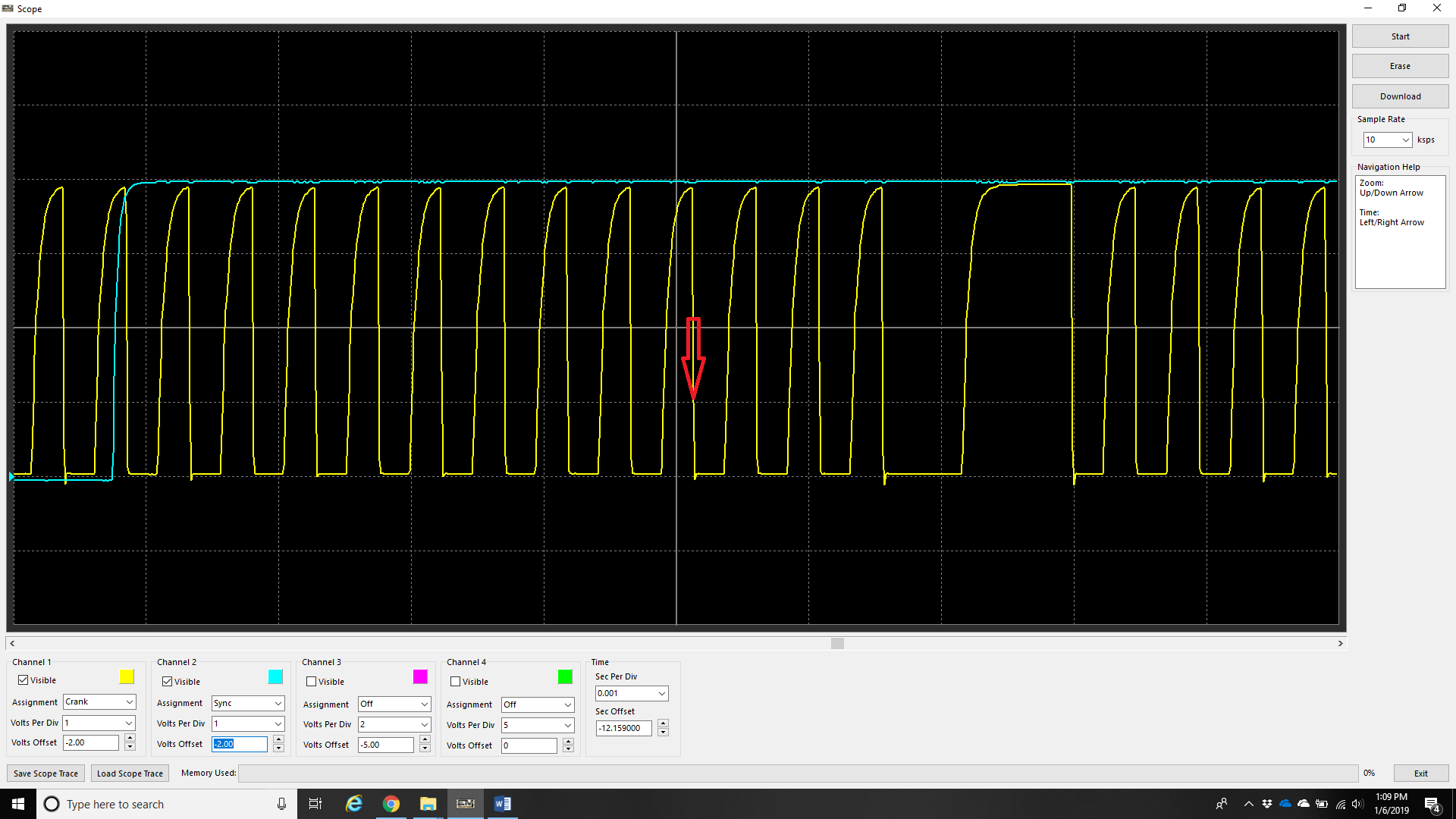
An example of a hall senor fast edge being the falling. Most hall sensors produce a very good “square” wave, so the point can be argued that rising edge can be used, however at higher revs some will produce this “saw tooth” pattern which means triggering that way will cause timing to wander.
Rising and Falling Edge Sync Mode
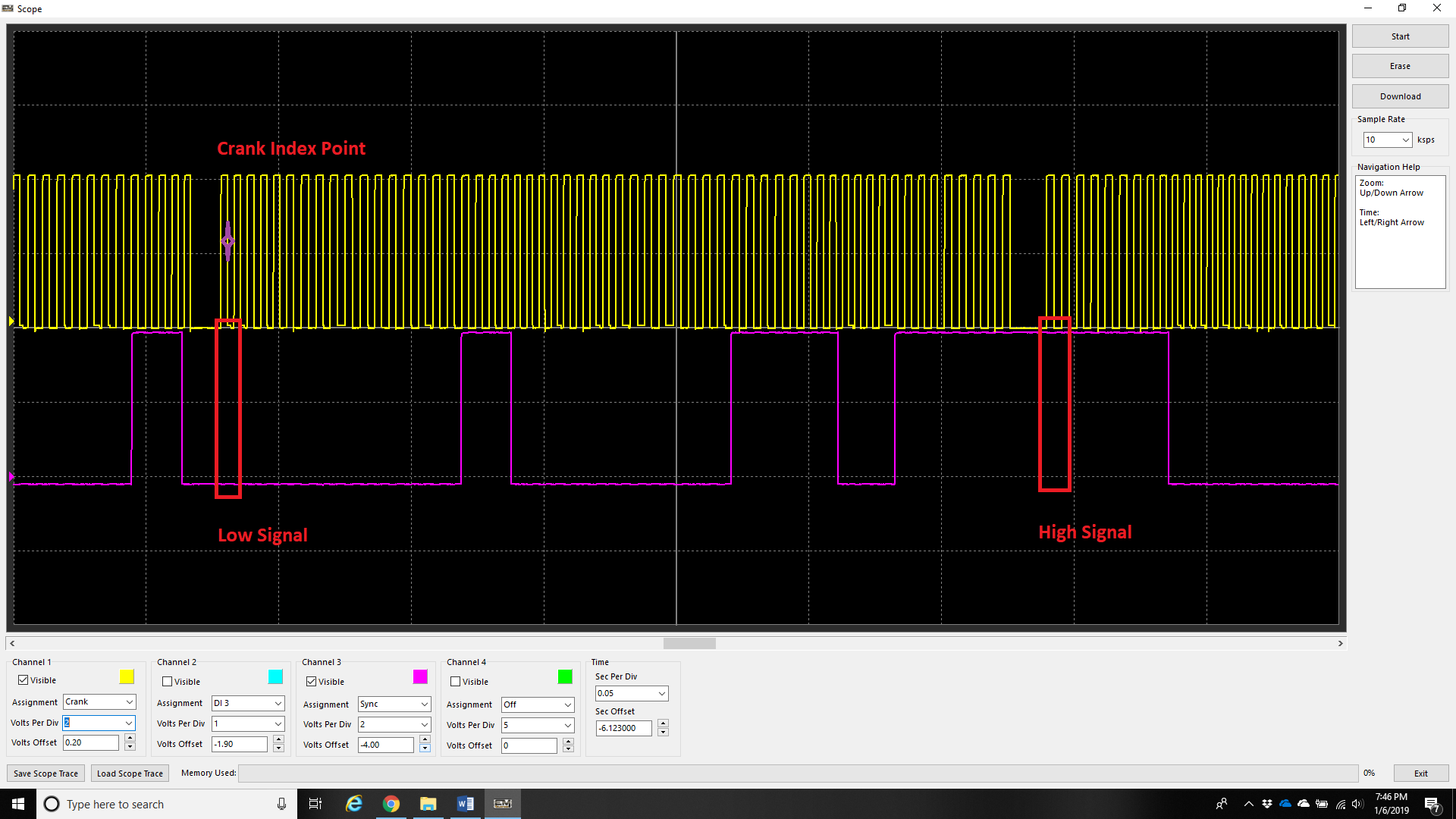
Engines with multi-tooth sync sensors usually will have a “long” tooth during the “crank index point”. Normally, a custom decoding mode is needed to run the engine with multiple sync teeth, but in this case because there is a clear difference in signal on the sync input on each stroke (low vs high), the ECU can determine the stroke immediately (this is the fastest way to decode starting/720 sync). Set Sync Sensor Edge configuration to Rising and Falling for these trigger types.
** See Sync Sensor Setup – Sync Sensor