Gear Management
Gear Management
The first step to proper gear management/detection is a properly scaled and validated speed signal.
Gear Management in Emtron can be detected in various ways.
Fundamentally, gear control and detection are a part of the ECU functions.
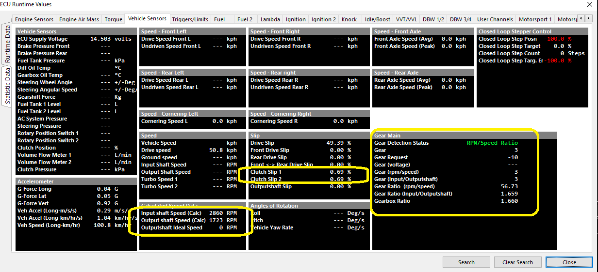
Several channels are linked to the gear functions that can be viewed, logged, and used as active channels :
Gear Position (RPM/Speed) Setup
Speed Lockout
Gear Detection Ratio Calculation stops when the speed fall below this value.
0 = OFF
Typical: 2-5.
Default Gear
Default gear for Gear Detection Ratio Calculation.
Gear Valid Time
Typical: 10ms
Tolerance
Typical: 10%
Fault Time
Fault Time for Gear Detection Ratio Calculation.
Typical: 1000ms
Clutch Switch Lockout
Gear Ratio Detection Calculation temporary stops when the Clutch Switch is ON i.e. during a gear change.
Clutch Switch Input Channel MUST be configured
Gear Position (RPM/Speed) Table
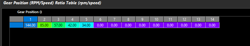
Define the multiplier here to get speed for the ratio calculation to work. IE:
100kph *34 in 5th gear = 3400rpm.
Speed channel must be configured and scaled
RPM/Speed ratio is also actively calculated in Runtimes
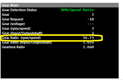
3rd gear engaged shown
Gear Position (Input/Outputshaft)
Gear Ratio (Input/Outputshaft Speed) = Inputshaft Speed Source/ Outputshaft Speed Source
Outputshaft Speed Lockout
Gear Detection Ratio Calculation stops when the Outputshaft speed fall below this value.
0 = OFF
Typical: 2-5.
Default Gear
Default gear for Gear Detection Ratio Calculation.
Gear Valid Time
Typical: 6ms
Tolerance
Typical: 7%
Fault Time
Typical: 10ms
Gear Position (Input/Outputshaft Speed) Table
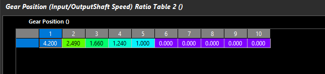
Define the transmission ratios the ECU should expect for calculating gears via Input/Outputshaft speed correlation
Actual Gear Ratio (Input/Outputshaft) can be validated actively calculated in Runtimes
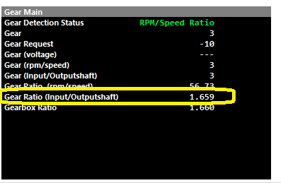
3rd gear engaged shown