Subsections of Vehicle
Clutch Slip Calculation
Clutch Slip Calculation uses 2 Inputs:
Engine Speed (RPM)
Input Shaft Speed (RPM)
Example.
Engine Speed = 6000
Input Shaft Speed = 5756 RPM
Clutch Slip(%) = Input Shaft Speed - Engine Speed
Engine Speed
Clutch Slip(%) = -4.06 %
This means the Input Shaft is rotating 4.06% slower than the Engine Speed… i.e 4.06% Clutch Slip.
Drive Slip Calculation
Drive Slip
Given as a percentage of the difference between the speed of the driven wheel compared to the speed of an undriven wheel. The Drive Slip can be both positive and negative.
Drive Slip = (Speed Channel 1 - Speed Channel 2) / Speed Channel 2
which is normally expressed as:
Drive Slip = (Driven wheel speed - undriven wheel speed) / undriven wheel speed
0.0% = The driven and undriven wheels are at the same speed.
+10.0% = The driven wheels are turning 10% faster than the non driven wheels.
-10.0% = The driven wheels are turning 10% slower than the non driven wheels .
Example 1 - Drive Slip settings. Front wheel drive, 4 wheel speed inputs connected.
Drive Speed Front L = DI 1
Drive Speed Front R = DI 2
Undriven Speed Rear L = DI 3
Undriven Speed Rear R = DI 4
The ECU will average the front wheel speed and load this value into the runtime " Front Axle Speed"
The ECU will average the rear wheel speed and load this value into the runtime " Rear Axle Speed"
Driven Speed Channel = Front Axle Speed
Undriven Speed Channel = Rear Axle Speed
Example 2 - Drive Slip Settings. Rear wheel drive, 4 wheel speed inputs connected.
Undriven Speed Front L = DI 1
Undriven Speed Front R = DI 2
Drive Speed Rear L = DI 3
Drive Speed Rear R = DI 4
The ECU will average the front wheel speed and load this value into the runtime " Front Axle Speed"
The ECU will average the rear wheel speed and load this value into the runtime " Rear Axle Speed"
Driven Speed Channel = Rear Axle Speed
Undriven Speed Channel = Front Axle Speed
Turning Slip
The difference between the wheel speeds on the left side of the vehicle and the wheel speeds on the right side of the vehicle. The ECU uses “Front Axle Speed” and “Rear Axle Speed” to calculate this.
ECU calculated values: If sufficient Input Speed channels are selected the ECU can calculate the following addition data.
Front Axle Speed.
The average of either:
The Drive Speed Front L and R orThe Undriven Speed Front L and R
Rear Axle Speed.
The average of either:
The Drive Speed Rear L and R orThe Undriven Speed Rear L and R
Cornering Speed L.
The average of the Speed Front L (driven or undriven) and Speed Rear L (driven or undriven)
Cornering Speed R.
The average of the Speed Front R (driven or undriven) and Speed Rear R (driven or undriven)
NOTE: The ECU will check which speed channels are assigned and use this information to calculate the data. For this to work correctly for example the Speed Front L Driven and Undriven channels can never both be selected.
Gear Management
Gear Management
The first step to proper gear management/detection is a properly scaled and validated speed signal.
Gear Management in Emtron can be detected in various ways.
Fundamentally, gear control and detection are a part of the ECU functions.
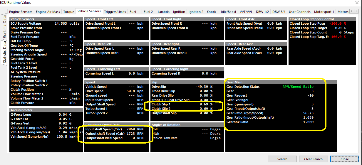
Several channels are linked to the gear functions that can be viewed, logged, and used as active channels :
Gear Position (RPM/Speed) Setup
Speed Lockout
Gear Detection Ratio Calculation stops when the speed fall below this value.
0 = OFF
Typical: 2-5.
Default Gear
Default gear for Gear Detection Ratio Calculation.
Gear Valid Time
Typical: 10ms
Tolerance
Typical: 10%
Fault Time
Fault Time for Gear Detection Ratio Calculation.
Typical: 1000ms
Clutch Switch Lockout
Gear Ratio Detection Calculation temporary stops when the Clutch Switch is ON i.e. during a gear change.
Clutch Switch Input Channel MUST be configured
Gear Position (RPM/Speed) Table

Define the multiplier here to get speed for the ratio calculation to work. IE:
100kph *34 in 5th gear = 3400rpm.
Speed channel must be configured and scaled
RPM/Speed ratio is also actively calculated in Runtimes
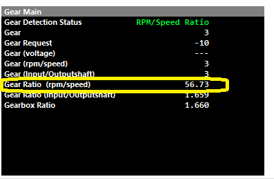
3rd gear engaged shown
Gear Position (Input/Outputshaft)
Gear Ratio (Input/Outputshaft Speed) = Inputshaft Speed Source/ Outputshaft Speed Source
Outputshaft Speed Lockout
Gear Detection Ratio Calculation stops when the Outputshaft speed fall below this value.
0 = OFF
Typical: 2-5.
Default Gear
Default gear for Gear Detection Ratio Calculation.
Gear Valid Time
Typical: 6ms
Tolerance
Typical: 7%
Fault Time
Typical: 10ms
Gear Position (Input/Outputshaft Speed) Table
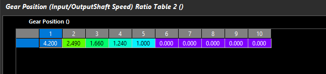
Define the transmission ratios the ECU should expect for calculating gears via Input/Outputshaft speed correlation
Actual Gear Ratio (Input/Outputshaft) can be validated actively calculated in Runtimes
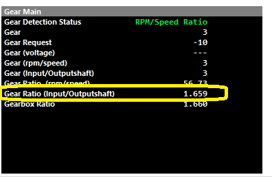
3rd gear engaged shown