Subsections of Datasheets
KV8 ECU Data Sheet
General
Emtron’s KV8 is a wire in ECU with extreme flexibility. Industry leading I/O count will ensure you do not have to make any sacrifices when configuring your engine and vehicle. This ECU will support up to 8 Channels of fuel and 8 Channels fully sequential Ignition. Every KV8 is housed in a durable billet Aluminium enclosure and includes up to 32MB permanent memory for on board logging, 4-channel oscilloscope function, DBW control up to 2 channels, dual on-board LSU4.9 Lambda controllers, dual digital Knock control, Ethernet communications and 3 axis G-force sensing to name a few.
Power Supply
- Operating voltage: 6.0 to 22.0 Volts DC (ECU shutdowns at 24.0V)
- Operating current: 390mA at 14.0V (excluding sensor and load currents)
- Reverse battery protection via external fuse
- “Smart” battery transient protection
Operating Temperature
- Max operating range: -30 to 110°C (-22 to 230°F)
- Recommended operating range: -30 to 85°C (-22 to 185°F)
Physical
- Aluminium 6061 grade CNC billet enclosure
- Enclosure size 134 mm x 162 mm x 27 mm
- Weight: 730g
- Connector system: 120-way Super Seal waterproof connectors with gold plated contacts
- Pin diameter: 1 mm
- Current rating: maximum 15A per pin (wire gauge dependant)
- Connector A: 26 pin Key 2 Super Seal
- Connector B: 34 pin Key 2 Super Seal
- Connector C: 34 pin Key 1 Super Seal
- Connector D: 26 pin Key 1 Super Seal
Internal
Dual 100MHz processors
500Mb DDR RAM (0.5Gb)
32MB ECU logging memory
- Over 1200 channels available
- 1Hz to 500Hz logging rate
Oscilloscope 4-channel function with 32MB storage
- Sampling at 100k samples/second
- Includes Crank and Cam sensor inputs
- Includes Digital inputs 1-4
On-Board barometric pressure sensor
- Range 40 - 115.0 kPa
3-Axis accelerometer
- 16-Bit resolution
- +2g/+4g/+8g dynamically selectable full-scale
- Output data rate 500Hz
Outputs
8x Port Injector Outputs—high or low ohm
- Flyback Voltage Clamp 70V
- Independent Saturated or Peak & Hold control per channel
- 8A Peak, 4A hold, 10A Limit Injector Control
- Outputs can be used for ground switching, 6A Continuous, 10A Limit
- All outputs are short circuit and over current protected
- No Flywheel diodes (external diode(s) required for VVT control)
8x Ignition Outputs
- Open collector outputs with Logic Level outputs
- Adjustable Ignition drive current (35mA or 70mA)
- Outputs can be used for Auxiliary ground switching, 1A Continuous, 3A Limit
- All outputs are short circuit and over current protected
- No Flywheel diodes (external diode(s) required for VVT control)
- Ignitor must be used between ECU and coil
16x Auxiliary Outputs
Variable Valve Timing (VVT) and Variable Valve Timing Electric (VTiE), Drive by Wire (DBW) up to 2 throttle bodies, dual boost control, gearshift solenoids, stepper motor and many more.
All outputs have PWM control, maximum frequency = 15 kHz
Flywheel diodes integrated into all outputs
- Auxiliary 1-8 Flywheel to the “ECU Supply” pin D1 connector D
- Auxiliary 9-12 Flywheel to the “ECU 9-12 Supply” pin D20 connector D
- Auxiliary 13-16 Flywheel to the “ECU 13-16 Supply” pin D2 connector D
All outputs are short circuit and over current protected
Low Side Drivers
Auxiliary 1-4: Low Side 4A continuous, 6A peak modulated, 8A limit
Auxiliary 5-8: Low Side 2.5A continuous, 4A peak modulated, 5A limit
High Side Drivers
- Auxiliary 1-8: High Side 4A continuous, 9A limit
Half Bridge Drivers
- Auxiliary 9-12: Half Bridge 5A continuous and 8A limit. Can be used as Low Side, High Side or together for DC motor control (DBW up to 2x channels)
- Auxiliary 13-16: Half Bridge 15.0A continuous (pin limited). Can be used as Low Side or High Side.
1x EFI Relay Output
- Low Side Driver for relay control. Current limited to 200mA (Output will switch ON when Ignition Switch Input (D15) is greater than 4V).
1x Analog Output Buffered
- Voltage range 0.0 - 5.0V, output current 100mA
1x Shield Output
- Connection for Trigger and Knock shielded cables. Short to battery protection
Inputs
16x Analog Voltage/Temperature Inputs
- Fully configurable including custom calibrations
- Switchable 1k ohm pull-up resistors on ANV 7-12 (available on 6 channels)
- Accepts a 0.0 - 5.000V analog input range. Resolution is 1.22mV (12-Bit)
- Input Impedance 100k Ohms to ground
- 160Hz Low pass filter
8x Digital/Speed Inputs (DI 1 - 8)
- Frequency range from 0.0Hz up the 30.0kHz on all 8 channels
- Magnetic and hall/optical effect sensor compatible with programmable trigger edge(s)
- Independent programmable frequency-based arming threshold control, range 0.0 - 12.0V
- Wheel speed, output shaft speed, turbo speed and other frequency-based signals
- VVT position(s) up to 4 channels available on DI 1- 4.
- Accepts a 0.0 - 20.0V analog input. Effective resolution is 4.88mV (10-Bit)
- On/Off switched inputs: AC request, launch enable, cruise switch, table control switching etc with programable switch-based arming threshold control, range 0.0 - 20.0V
- Switchable 4k7 ohm pull-up resistors on all 8 channels to 10.0V
- Maximum/Minimum input signal amplitude +/- 80V
6x Digital/Switched Inputs (DI 9 - 14)
- On/Off switched inputs: AC request, Launch enable, cruise switch, table control switching etc with programable switch-based arming threshold control, range 0.0 - 20.0V
- Accepts a 0.0 -20.0 V analog input. Effective resolution is 19.61mV (8-Bit)
- Switchable 4k7 ohm pull-up resistors on all 6 channels to 10.0V
2x Knock Inputs
- 2 Independent knock input channels
- Using Bosch, Digital Knock Integrated Circuit Technology with programmable digital filter coefficients
- Center frequency configurable from 500Hz - 25kHz
- Bandwidth window from 100Hz - 5kHz
- Digital filter window; Hamming or Blackman
- Gain control(x1, x2, x4, x8)
- Cylinder selectable knock input
- Knock control available on ALL Ignition modes (Direct, Wasted, Distributor etc)
1x Dedicated Ignition Switch Input
- 6.0 - 20.0V input used for EFI Relay Control. (With input > 4V the EFI Relay output (D9) will switch ON)
2x Crank Index and Sync Engine Decoding Inputs
- Magnetic and Hall effect sensor compatible with programable trigger edge(s)
- “True” zero crossing detection on magnetic signals for precise engine position decoding.
- Programmable independent arming threshold control from 0.1V to 12.0V
- Switchable 4k7 ohm pull-up resistor to 5V
- OEM patterns supported
- Maximum input signal amplitude +/- 80V
- Input Impedance 39k ohms to ground
Lambda
Two Lambda channels supporting the Bosch LSU 4.9 sensor
- Using Bosch integrated circuit technology for precise sensor control
- Nernst cell temperature measurement for dynamic PID closed loop heater control
- Lambda range: 0.580 La to 10.000 La
- Diagnostics available for each pin and includes, Short to ground, Short to Vbat, Open Load
Voltage and Ground Supplies
1x ECU Supply Input
- 15.0A Max (pin limited)
- 6V - 22.0V Range
- Supplies ECU power
- Supplies Auxiliary 1-8 High Side Drivers
1x Auxiliary 9-12 Supply Input
- 15.0A Max (pin limited)
- Power supply for Auxiliary channels 9 -12. (See KV Series Power Distribution Wiring - A10.pdf for more information on how this should be wired)
1x Auxiliary 13-16 Supply Input
- 15.0A Max (pin limited)
- Power supply for Auxiliary channels 13 -16. See KV Series Power Distribution Wiring - A10.pdf for more information on how this should be wired)
2x 5.0V Sensor Supply
- 5V Vref1 output current 400mA
- 5V Vref2 output current 400mA
- Accuracy: +/- 1.0% at 25 °C
- Short circuit, Reverse Battery Protection, Thermal overload protection
- Operating temperature range -40°C ~ 125°C
1x 8.0V Sensor Supply
- Output current 600mA
- Accuracy: +/- 1.0% at 25 °C
- Short circuit, Reverse battery protection, Thermal overload protection
- Operating temperature range -40°C ~ 125°C
4x ECU Main Grounds
- 15.0A per pin, total 60A
2x Sensor 0V Reference
- Analog Sensor 0V Reference with short to battery protection
NOTE: The Sensor 0V Reference pin(s) are specialised ground outputs for all analog sensors. Connect direct to the sensor 0V pin, DO NOT connect to the Engine Block or ECU Ground.
Communications
- 1x High Speed Ethernet 100Mbps for tuning software connection
- 2x CAN 2.0B 1Mbps/ 6 Channels per node, total 128 messages
KV12 Rev2 Data Sheet
General
Emtron’s KV12 is a wire in ECU with extreme flexibility. Industry leading I/O count will ensure you do not have to make any sacrifices when configuring your engine and vehicle. This ECU will support up to 12 Channels of fuel and 12 Channels fully sequential Ignition. Every KV12 is housed in a durable billet Aluminium enclosure and includes up to 32MB permanent memory for on board logging, 4-channel oscilloscope function, DBW control up to 2 channels, dual on-board LSU4.9 Lambda controllers, dual digital Knock control, Ethernet communications and 3 axis G-force sensing to name a few.
Power Supply
- Operating voltage: 6.0 to 22.0 Volts DC (ECU shutdowns at 24.0V)
- Operating current: 390mA at 14.0V (excluding sensor and load currents)
- Reverse battery protection via external fuse
- “Smart” battery transient protection
Operating Temperature
- Max operating range: -30 to 110°C (-22 to 230°F)
- Recommended operating range: -30 to 85°C (-22 to 185°F)
Physical
- Aluminium 6061 grade CNC billet enclosure
- Enclosure size 134 mm x 162 mm x 27 mm
- Weight: 730g
- Connector system: 120-way Super Seal waterproof connectors with gold plated contacts
- Pin diameter: 1 mm
- Current rating: maximum 15A per pin (wire gauge dependant)
- Connector A: 26 pin Key 2 Super Seal
- Connector B: 34 pin Key 2 Super Seal
- Connector C: 34 pin Key 1 Super Seal
- Connector D: 26 pin Key 1 Super Seal
Internal
Dual 100MHz processors
500Mb DDR RAM (0.5Gb)
32MB ECU logging memory
- Over 1200 channels available
- 1Hz to 500Hz logging rate
Oscilloscope 4-channel function with 32MB storage
- Sampling at 100k samples/second
- Includes Crank and Cam sensor inputs
- Includes Digital inputs 1-4
On-Board barometric pressure sensor
- Range 40 - 115.0 kPa
3-Axis accelerometer
- 16-Bit resolution
- +2g/+4g/+8g dynamically selectable full-scale
- Output data rate 500Hz
Outputs
12x Port Injector Outputs—high or low ohm
- Flyback Voltage Clamp 70V
- Independent Saturated or Peak & Hold control per channel
- 8A Peak, 4A hold, 10A Limit Injector Control
- Outputs can be used for ground switching, 6A Continuous, 10A Limit
- All outputs are short circuit and over current protected
- No Flywheel diodes (external diode(s) required for VVT control)
12x Ignition Outputs
- Open collector outputs with Logic Level outputs
- Adjustable Ignition drive current (35mA or 70mA)
- Outputs can be used for Auxiliary ground switching, 1A Continuous, 3A Limit
- All outputs are short circuit and over current protected
- No Flywheel diodes (external diode(s) required for VVT control)
- Ignitor must be used between ECU and coil
16x Auxiliary Outputs
Variable Valve Timing (VVT) and Variable Valve Timing Electric (VTiE), Drive by Wire (DBW) up to 2 throttle bodies, dual boost control, gearshift solenoids, stepper motor and many more.
All outputs have PWM control, maximum frequency = 15 kHz
Flywheel diodes integrated into all outputs
- Auxiliary 1-8 Flywheel to the “ECU Supply” pin D1 connector D
- Auxiliary 9-12 Flywheel to the “ECU 9-12 Supply” pin D20 connector D
- Auxiliary 13-16 Flywheel to the “ECU 13-16 Supply” pin D2 connector D
All outputs are short circuit and over current protected
Low Side Drivers
Auxiliary 1-4: Low Side 4A continuous, 6A peak modulated, 8A limit
Auxiliary 5-8: Low Side 2.5A continuous, 4A peak modulated, 5A limit
High Side Drivers
- Auxiliary 1-8: High Side 4A continuous, 9A limit
Half Bridge Drivers
- Auxiliary 9-12: Half Bridge 5A continuous and 8A limit. Can be used as Low Side, High Side or together for DC motor control (DBW up to 2x channels)
- Auxiliary 13-16: Half Bridge 15.0A continuous (pin limited). Can be used as Low Side, High Side or together for DC motor control (DBW up to 2x channels)
(NOTE: Auxiliary 9 -16 can be used to control up to 4x DBW throttle bodies)
1x EFI Relay Output
- Low Side Driver for relay control. Current limited to 200mA (Output will switch ON when Ignition Switch Input (D15) is greater than 4V).
1x Analog Output Buffered
- Voltage range 0.0 - 5.0V, output current 100mA
1x Shield Output
- Connection for Trigger and Knock shielded cables. Short to battery protection
Inputs
16x Analog Voltage/Temperature Inputs.
- Fully configurable including custom calibrations
- Switchable 1k ohm pull-up resistors on ANV 7-12 (available on 6 channels)
- Accepts a 0.0 - 5.000V analog input range. Resolution is 1.22mV (12-Bit)
- Input Impedance 100k Ohms to ground
- 160Hz Low pass filter
8x Digital/Speed Inputs (DI 1 - 8)
- Frequency range from 0.0Hz up the 30.0kHz on all 8 channels
- Magnetic and hall/optical effect sensor compatible with programmable trigger edge(s)
- Independent programmable frequency-based arming threshold control, range 0.0 - 12.0V
- Wheel speed, output shaft speed, turbo speed and other frequency-based signals
- VVT position(s) up to 4 channels available on DI 1- 4.
- Accepts a 0.0 - 20.0V analog input. Effective resolution is 4.88mV (10-Bit)
- On/Off switched inputs: AC request, launch enable, cruise switch, table control switching etc with programable switch-based arming threshold control, range 0.0 - 20.0V
- Switchable 4k7 ohm pull-up resistors on all 8 channels to 10.0V
- Maximum/Minimum input signal amplitude +/- 80V
6x Digital/Switched Inputs (DI 9 - 14)
- On/Off switched inputs: AC request, Launch enable, cruise switch, table control switching etc with programable switch-based arming threshold control, range 0.0 - 20.0V
- Accepts a 0.0 -20.0 V analog input. Effective resolution is 19.61mV (8-Bit)
- Switchable 4k7 ohm pull-up resistors on all 6 channels to 10.0V
2x Knock Inputs
- 2 Independent knock input channels
- Using Bosch, Digital Knock Integrated Circuit Technology with programmable digital filter coefficients
- Center frequency configurable from 500Hz - 25kHz
- Bandwidth window from 100Hz - 5kHz
- Digital filter window; Hamming or Blackman
- Gain control(x1, x2, x4, x8)
- Cylinder selectable knock input
- Knock control available on ALL Ignition modes (Direct, Wasted, Distributor etc)
1x Dedicated Ignition Switch Input
- 6.0 - 20.0V input used for EFI Relay Control. (With input > 4V the EFI Relay output (D9) will switch ON)
2x Crank Index and Sync Engine Decoding Inputs
- Magnetic and Hall effect sensor compatible with programable trigger edge(s)
- “True” zero crossing detection on magnetic signals for precise engine position decoding.
- Programmable independent arming threshold control from 0.1V to 12.0V
- Switchable 4k7 ohm pull-up resistor to 5V
- OEM patterns supported
- Maximum input signal amplitude +/- 80V
- Input Impedance 39k ohms to ground
Lambda
Two Lambda channels supporting the Bosch LSU 4.9 sensor
- Using Bosch integrated circuit technology for precise sensor control
- Nernst cell temperature measurement for dynamic PID closed loop heater control
- Lambda range: 0.580 La to 10.000 La
- Diagnostics available for each pin and includes, Short to ground, Short to Vbat, Open Load
Voltage and Ground Supplies
1x ECU Supply Input
- 15.0A Max (pin limited)
- 6V - 22.0V Range
- Supplies ECU power
- Supplies Auxiliary 1-8 High Side Drivers
1x Auxiliary 9-12 Supply Input
- 15.0A Max (pin limited)
- Power supply for Auxiliary channels 9 -12. (See KV Series Power Distribution Wiring - A10.pdf for more information on how this should be wired)
1x Auxiliary 13-16 Supply Input
- 15.0A Max (pin limited)
- Power supply for Auxiliary channels 13 -16. See KV Series Power Distribution Wiring - A10.pdf for more information on how this should be wired)
2x 5.0V Sensor Supply
- 5V Vref1 output current 400mA
- 5V Vref2 output current 400mA
- Accuracy: +/- 1.0% at 25 °C
- Short circuit, Reverse Battery Protection, Thermal overload protection
- Operating temperature range -40°C ~ 125°C
1x 8.0V Sensor Supply
- Output current 600mA
- Accuracy: +/- 1.0% at 25 °C
- Short circuit, Reverse battery protection, Thermal overload protection
- Operating temperature range -40°C ~ 125°C
5x ECU Main Grounds
- 15.0A per pin, total 60A
2x Sensor 0V Reference
- Analog Sensor 0V Reference with short to battery protection
NOTE: The Sensor 0V Reference pin(s) are specialised ground outputs for all analog sensors. Connect direct to the sensor 0V pin, DO NOT connect to the Engine Block or ECU Ground.
Communications
- 1x High Speed Ethernet 100Mbps for tuning software connection
- 2x CAN 2.0B 1Mbps/ 6 Channels per node, total 128 messages
KV16 Rev2 Data Sheet
General
Emtron’s KV16 is a wire in ECU with extreme flexibility. Industry leading I/O count will ensure you do not have to make any sacrifices when configuring your engine and vehicle. This ECU will support up to 16 Channels of fuel and 12 Channels fully sequential Ignition. Every KV16 is housed in a durable billet Aluminium enclosure and includes up to 32MB permanent memory for on board logging, 4-channel oscilloscope function, DBW control up to 4 channels, dual on-board LSU4.9 Lambda controllers, dual digital Knock control, Ethernet communications and 3 axis G-force sensing to name a few.
Power Supply
- Operating voltage: 6.0 to 22.0 Volts DC (ECU shutdowns at 24.0V)
- Operating current: 390mA at 14.0V (excluding sensor and load currents)
- Reverse battery protection via external fuse
- “Smart” battery transient protection
Operating Temperature
- Max operating range: -30 to 110°C (-22 to 230°F)
- Recommended operating range: -30 to 85°C (-22 to 185°F)
Physical
- Aluminium 6061 grade CNC billet enclosure
- Enclosure size 134 mm x 162 mm x 27 mm
- Weight: 730g
- Connector system: 120-way Super Seal waterproof connectors with gold plated contacts
- Pin diameter: 1 mm
- Current rating: maximum 15A per pin (wire gauge dependant)
- Connector A: 26 pin Key 2 Super Seal
- Connector B: 34 pin Key 2 Super Seal
- Connector C: 34 pin Key 1 Super Seal
- Connector D: 26 pin Key 1 Super Seal
Internal
Dual 100MHz processors
500Mb DDR RAM (0.5Gb)
32MB ECU logging memory
- Over 1200 channels available
- 1Hz to 500Hz logging rate
Oscilloscope 4-channel function with 32MB storage
- Sampling at 100k samples/second
- Includes Crank and Cam sensor inputs
- Includes Digital inputs 1-4
On-Board barometric pressure sensor
- Range 40 - 115.0 kPa
3-Axis accelerometer
- 16-Bit resolution
- +2g/+4g/+8g dynamically selectable full-scale
- Output data rate 500Hz
Outputs
16x Port Injector Outputs—high or low ohm
- Flyback Voltage Clamp 70V
- Independent Saturated or Peak & Hold control per channel
- 8A Peak, 4A hold, 10A Limit Injector Control
- Outputs can be used for ground switching, 6A Continuous, 10A Limit
- All outputs are short circuit and over current protected
- No Flywheel diodes (external diode(s) required for VVT control)
12x Ignition Outputs
- Open collector outputs with Logic Level outputs
- Adjustable Ignition drive current (35mA or 70mA)
- Outputs can be used for Auxiliary ground switching, 1A Continuous, 3A Limit
- All outputs are short circuit and over current protected
- No Flywheel diodes (external diode(s) required for VVT control)
- Ignitor must be used between ECU and coil
16x Auxiliary Outputs
Variable Valve Timing (VVT) and Variable Valve Timing Electric (VTiE), Drive by Wire (DBW) up to 2 throttle bodies, dual boost control, gearshift solenoids, stepper motor and many more.
All outputs have PWM control, maximum frequency = 15 kHz
Flywheel diodes integrated into all outputs
- Auxiliary 1-8 Flywheel to the “ECU Supply” pin D1 connector D
- Auxiliary 9-12 Flywheel to the “ECU 9-12 Supply” pin D20 connector D
- Auxiliary 13-16 Flywheel to the “ECU 13-16 Supply” pin D2 connector D
All outputs are short circuit and over current protected
Low Side Drivers
Auxiliary 1-4: Low Side 4A continuous, 6A peak modulated, 8A limit
Auxiliary 5-8: Low Side 2.5A continuous, 4A peak modulated, 5A limit
High Side Drivers
- Auxiliary 1-8: High Side 4A continuous, 9A limit
Half Bridge Drivers
- Auxiliary 9-12: Half Bridge 5A continuous and 8A limit. Can be used as Low Side, High Side or together for DC motor control (DBW up to 2x channels)
- Auxiliary 13-16: Half Bridge 15.0A continuous (pin limited). Can be used as Low Side, High Side or together for DC motor control (DBW up to 2x channels)
(NOTE: Auxiliary 9 -16 can be used to control up to 4x DBW throttle bodies)
1x EFI Relay Output
- Low Side Driver for relay control. Current limited to 200mA (Output will switch ON when Ignition Switch Input (D15) is greater than 4V).
1x Analog Output Buffered
- Voltage range 0.0 - 5.0V, output current 100mA
1x Shield Output
- Connection for Trigger and Knock shielded cables. Short to battery protection
Inputs
16x Analog Voltage/Temperature Inputs.
- Fully configurable including custom calibrations
- Switchable 1k ohm pull-up resistors on ANV 7-12 (available on 6 channels)
- Accepts a 0.0 - 5.000V analog input range. Resolution is 1.22mV (12-Bit)
- Input Impedance 100k Ohms to ground
- 160Hz Low pass filter
8x Digital/Speed Inputs (DI 1 - 8)
- Frequency range from 0.0Hz up the 30.0kHz on all 8 channels
- Magnetic and hall/optical effect sensor compatible with programmable trigger edge(s)
- Independent programmable frequency-based arming threshold control, range 0.0 - 12.0V
- Wheel speed, output shaft speed, turbo speed and other frequency-based signals
- VVT position(s) up to 4 channels available on DI 1- 4.
- Accepts a 0.0 - 20.0V analog input. Effective resolution is 4.88mV (10-Bit)
- On/Off switched inputs: AC request, launch enable, cruise switch, table control switching etc with programable switch-based arming threshold control, range 0.0 - 20.0V
- Switchable 4k7 ohm pull-up resistors on all 8 channels to 10.0V
- Maximum/Minimum input signal amplitude +/- 80V
6x Digital/Switched Inputs (DI 9 - 14)
- On/Off switched inputs: AC request, Launch enable, cruise switch, table control switching etc with programable switch-based arming threshold control, range 0.0 - 20.0V
- Accepts a 0.0 -20.0 V analog input. Effective resolution is 19.61mV (8-Bit)
- Switchable 4k7 ohm pull-up resistors on all 6 channels to 10.0V
2x Knock Inputs
- 2 Independent knock input channels
- Using Bosch, Digital Knock Integrated Circuit Technology with programmable digital filter coefficients
- Center frequency configurable from 500Hz - 25kHz
- Bandwidth window from 100Hz - 5kHz
- Digital filter window; Hamming or Blackman
- Gain control(x1, x2, x4, x8)
- Cylinder selectable knock input
- Knock control available on ALL Ignition modes (Direct, Wasted, Distributor etc)
1x Dedicated Ignition Switch Input
- 6.0 - 20.0V input used for EFI Relay Control. (With input > 4V the EFI Relay output (D9) will switch ON)
2x Crank Index and Sync Engine Decoding Inputs
- Magnetic and Hall effect sensor compatible with programable trigger edge(s)
- “True” zero crossing detection on magnetic signals for precise engine position decoding.
- Programmable independent arming threshold control from 0.1V to 12.0V
- Switchable 4k7 ohm pull-up resistor to 5V
- OEM patterns supported
- Maximum input signal amplitude +/- 80V
- Input Impedance 39k ohms to ground
Lambda
Two Lambda channels supporting the Bosch LSU 4.9 sensor
- Using Bosch integrated circuit technology for precise sensor control
- Nernst cell temperature measurement for dynamic PID closed loop heater control
- Lambda range: 0.580 La to 10.000 La
- Diagnostics available for each pin and includes, Short to ground, Short to Vbat, Open Load
Voltage and Ground Supplies
1x ECU Supply Input
- 15.0A Max (pin limited)
- 6V - 22.0V Range
- Supplies ECU power
- Supplies Auxiliary 1-8 High Side Drivers
1x Auxiliary 9-12 Supply Input
- 15.0A Max (pin limited)
- Power supply for Auxiliary channels 9 -12. (See KV Series Power Distribution Wiring - A10.pdf for more information on how this should be wired)
1x Auxiliary 13-16 Supply Input
- 15.0A Max (pin limited)
- Power supply for Auxiliary channels 13 -16. See KV Series Power Distribution Wiring - A10.pdf for more information on how this should be wired)
2x 5.0V Sensor Supply
- 5V Vref1 output current 400mA
- 5V Vref2 output current 400mA
- Accuracy: +/- 1.0% at 25 °C
- Short circuit, Reverse Battery Protection, Thermal overload protection
- Operating temperature range -40°C ~ 125°C
1x 8.0V Sensor Supply
- Output current 600mA
- Accuracy: +/- 1.0% at 25 °C
- Short circuit, Reverse battery protection, Thermal overload protection
- Operating temperature range -40°C ~ 125°C
6x ECU Main Grounds
- 15.0A per pin, total 60A
2x Sensor 0V Reference
- Analog Sensor 0V Reference with short to battery protection
NOTE: The Sensor 0V Reference pin(s) are specialised ground outputs for all analog sensors. Connect direct to the sensor 0V pin, DO NOT connect to the Engine Block or ECU Ground.
Communications
- 1x High Speed Ethernet 100Mbps for tuning software connection
- 2x CAN 2.0B 1Mbps/ 6 Channels per node, total 128 messages
KV16M Data Sheet
General
Emtron’s KV16M is a motorsport wire-in ECU with extreme flexibility built on the race proven KV16 ECU platform with additional flexibility and reliability utilising a 136-way Deutsch Autosport connector system. This ECU will support up to 16 Channels of fuel and 12 Channels fully sequential Ignition. Every KV16M is housed in a durable billet Aluminium enclosure and includes up to 32MB permanent memory for on board logging, 4-channel oscilloscope function, 24 high resolution analog inputs, DBW control up to 4 channels, dual on-board LSU4.9 Lambda controllers, dual digital Knock control, Ethernet communications and 3 axis G-force sensing to name a few.
Power Supply
- Operating voltage: 6.0 to 22.0 Volts DC (ECU shutdowns at 24.0V)
- Operating current: 450mA at 14.0V (excluding sensor and load currents)
- Reverse battery protection via external fuse
- “Smart” battery transient protection
- “Smart” internal ECU hold power control
Operating Temperature
- Max operating range: -30 to 110°C (-22 to 230°F)
- Recommended operating range: -30 to 85°C (-22 to 185°F)
Physical
- Aluminium 6061 grade CNC billet enclosure
- Enclosure size 134 mm x 162 mm x 27 mm
- Weight: 750g
- Waterproof
- Connector system: 136-way waterproof connectors with gold plated contacts
* 1 x 55 Way, shell size 16 Deutsch Autosport (Red)
* 1 x 26 Way, shell size 16 Deutsch Autosport (Red)
* 1 x 55 Way, shell size 16 Deutsch Autosport (Yellow)
Internal
Dual 100MHz processors
500Mb DDR RAM (0.5Gb)
32MB ECU logging memory
- Over 1200 channels available
- 1Hz to 500Hz logging rate
Oscilloscope 4-channel function with 32MB storage
- Sampling at 100k samples/second
- Includes Crank and Cam sensors inputs
- Includes Digital Inputs 1-4
3-Axis accelerometer
- 16 Bit resolution
- +2g/+4g/+8g dynamically selectable full-scale
- Output data rate 500Hz
2.0 Outputs
16x Injector Outputs—high or low ohm.
- Flyback Voltage Clamp 70V
- Independent Saturated or Peak & Hold control per channel
- 8A Peak, 4A hold, 10A Limit Injector Control
- Outputs can be used for ground switching, 6A Continuous, 10A Limit
- All outputs are short circuit and over current protected
- No Flywheel diodes (external diode(s) required for VVT control)
12x Ignition Outputs
- Open collector outputs with Logic Level outputs
- Adjustable Ignition drive current (35mA or 70mA)
- Outputs can be used for Auxiliary ground switching, 1A Continuous, 3A Limit
- All outputs are short circuit and over current protected
- No Flywheel diodes (external diode(s) required for VVT control)
- Ignitor must be used between ECU and coil
16x Auxiliary Outputs
Variable Valve Timing (VVT) and Variable Valve Timing Electric (VTiE), Drive by Wire(DBW) up to 4 throttle bodies, dual boost control, gearshift solenoids, stepper motor and many more.
All Outputs have PWM Control, maximum frequency = 15 kHz
Flywheel diodes integrated into all outputs
- Aux 1-8 Flywheel to the “Constant 14V Supply” pin 53 Connector C
- All other Auxiliaries Flywheel to the “ECU 14V Supply” pins
All Outputs are short circuit and over current protected
Low Side Drivers
Auxiliary 1-4: Low Side 4A continuous, 6A peak modulated, 8A limit
Auxiliary 5-8: Low Side 2.5A continuous, 4A peak modulated, 5A limit
High Side Drivers
- Auxiliary 1-8: High Side 4A continuous, 9A limit
Half Bridge Drivers
- Auxiliary 9-12: Half Bridge 5A continuous and 8A limit. Can be used as Low Side, High Side or together for DC motor control (DBW up to 2x channels)
- Auxiliary 13-16: Half Bridge 7.5A continuous (pin limited). Can be used as Low Side, High Side or together for DC motor control (DBW up to 2x channels)
(NOTE: Auxiliary 9 -16 can be used to control up to 4x DBW throttle bodies)
1x Analog Output Buffered
- Voltage range 0 - 5.0V, Output current 100mA
2x Shield Outputs
- Connection for Trigger and Knock shielded cables. Short to battery protection
3.0 Inputs
24x Analog Voltage/Temperature Inputs.
- Fully configurable including custom calibrations
- Switchable 1k ohm pull-up resistors on ANV 7-12 (available on 6 channels)
- Accepts a 0.0 - 5.000V analog input range. Resolution is 1.22mV (12-Bit)
- Input Impedance 100k Ohms to ground
- 160Hz Low pass filter
8x Digital/Speed Inputs (DI 1 - 8)
- Frequency range from 0.0Hz up the 30.0kHz on all 8 channels
- Magnetic and hall/optical effect sensor compatible with programable trigger edge(s)
- Independent programable frequency-based arming threshold control, range 0.0 - 12.0V
- Wheel speed, output shaft speed, turbo speed and other frequency-based signals
- VVT position(s) up to 4 channels available on DI 1- 4.
- Accepts a 0.0 - 20.0V analog input. Effective resolution is 4.88mV (10-Bit)
- On/Off switched inputs: AC request, launch enable, cruise switch, table control switching etc with programable switch-based arming threshold control, range 0.0 - 20.0V
- Switchable 4k7 ohm pull-up resistors on all 8 channels to 10.0V
- Maximum/Minimum input signal amplitude +/- 80V
6x Digital/Switched Inputs (DI 9 - 14)
- On/Off switched inputs: AC request, Launch enable, cruise switch, table control switching etc with programable switch-based arming threshold control, range 0.0 - 20.0V
- Accepts a 0.0 -20.0 V analog input. Effective resolution is 19.61mV (8-Bit)
- Switchable 4k7 ohm pull-up resistors on all 6 channels to 10.0V
2x Knock Inputs
- 2 Independent knock input channels
- Using Bosch, Digital Knock Integrated Circuit Technology with programmable digital filter coefficients
- Center frequency configurable from 500Hz - 25kHz
- Bandwidth window from 100Hz - 5kHz
- Digital filter window; Hamming or Blackman
- Gain control(x1, x2, x4, x8)
- Cylinder selectable knock input
- Knock control available on ALL Ignition modes (Direct, Wasted, Distributor etc)
2x Crank and Cam Inputs
- Magnetic and Hall effect sensor compatible with programable trigger edge(s)
- “True” zero crossing detection on magnetic signals for precise engine position decoding.
- Programmable independent arming threshold control from 0.1V to 12.0V
- Switchable 4k7 ohm pull-up resistor to 5V
- OEM patterns supported
- Maximum input signal amplitude +/- 80V
- Input Impedance 39k ohms to ground
4.0 Lambda
2x Lambda channels supporting the Bosch LSU 4.9 sensor
- Using Bosch integrated circuit technology for precise sensor control
- Nernst cell temperature measurement for dynamic PID closed loop heater control
- Lambda range: 0.580 La to 10.000 La
- Diagnostics available for each pin and includes, Short to ground, Short to Vbat, Open Load
5.0 Voltage and Ground Supplies
4x ECU Supply Inputs
- 7.5A per pin, total 30A
- 6V - 22.0V Range
- Supplies ECU power
- Supplies Auxiliary 1-8 High Side Drivers
- Supplies Auxiliary 9 -16 Half bridge Drivers
3x 5.0V Sensor Supply
- 5V Vref1 output current 400mA
- 5V Vref2 output current 400mA
- 5V Vref3 output current 400mA
- Accuracy: +/- 1.0% at 25 °C
- Short circuit, Reverse Battery Protection, Thermal overload protection
- Operating temperature range -40°C ~ 125°C
1x 8.0V Sensor Supply
- Output current 600mA
- Accuracy: +/- 1.0% at 25 °C
- Short circuit, Reverse battery protection, Thermal overload protection
- Operating temperature range -40°C ~ 125°C
1x Constant 14V Battery Supply
- Internal ECU EFI Relay Control (Keep-alive function)
- Flywheel supply for Auxiliary Channels 1-8
6x ECU Main Grounds
- 7.5A per pin, total 45A
4x Analog Sensor 0V Reference
- Analog Sensor 0V Reference with short to battery protection
NOTE: The Analog Sensor 0V Ref pin(s) are specialised ground outputs for all analog sensors. Connect direct to the sensor 0V pin, DO NOT connect to the Engine Block or ECU Ground.
6.0 Communications
- 1x High Speed Ethernet 100Mbps for tuning software connection
- 2x CAN 2.0B 1Mbps/ 6 Channels per node, total 128 messages
KV Series Hardware Manual
Emtron KV8 ECU Emtron KV12 ECU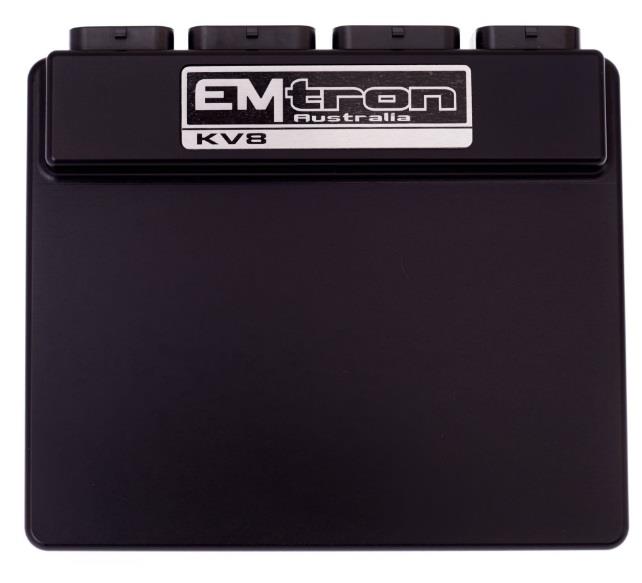
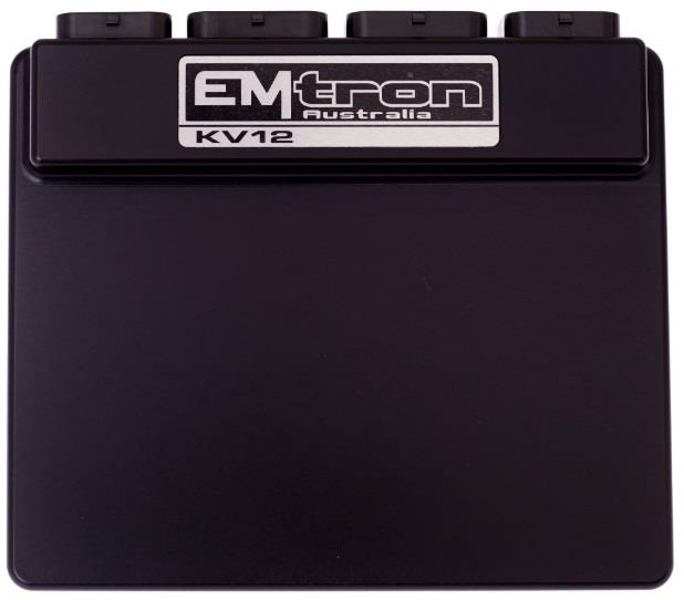
1.0 Analog Inputs
The KV series supports up to 24, 12-bit high resolution analog input channels.
| KV ECU | Analog Inputs |
|---|---|
| KV8 | 16 |
| KV12 | 16 |
| KV16 | 16 |
| KV16M | 24 |
1.1 Analog Input Channels 1-16/24
All analog input channels are sampled using high resolution 12-bit analog to digital converters with a 0.0 - 5.000V input range. The ECU uses a high precision internal voltage reference giving high-performance signal conversion. Analog channels 7-12 have configurable 1k ohm pullups so temperature sensors can be connected to these channels when required. All analog inputs can also be used as switched inputs with arming levels programmable from 0.0 – 5.0V.
Analog Voltage Input 1-24 Summary
- 16x/24x Analog Inputs with 6 channels available for temperature measurement with switchable pullup resistors
- Fully configurable including custom calibrations
- Switchable 1k ohm pull-up resistors on ANV 7-12 making these inputs suitable for temperature measurement. Pullup supply is to 5.0V Vref1.
- Every input accepts a 0.0 - 5.000V analog input range. Resolution is 1.22mV using a 12-bit analog to digital converter.
- Input Impedance 100k Ohms to ground
- 1st order 160Hz Low pass filter
- All inputs support ratiometric and absolute 3-wire based sensors such as MAP, Throttle position(s) and pressures etc
- AN7-12 support thermistor 2-wire sensors such as engine temperature, inlet air temperature with the pullup resistor switched ON when required.
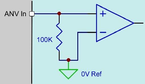
Simplified analog input channel — ANV In, 100 kΩ to ground, 0 V Ref.
1.2 Analog Temperature Input Channels 7-12
As mentioned in 1.1 these channels have switchable 1k pullup resistors. This allows these channels to support ratiometric and absolute sensors (Pullup switch OFF) or thermistors 2-wire sensors with the pullup(s) switched ON. When the pullup is enabled the ECU applies a ratiometric correction which maintains a very stable output independent of pullup supply variations.
Analog Voltage Input 7-12 Summary
- Switchable 1k ohm pull-up resistors, pullup supply to 5.0V Vref1.
- Every input accepts a 0.0 - 5.000V analog input range. Resolution is 1.22mV using a 12-bit analog to digital converter.
- Input Impedance 100k Ohms to ground
- 1st order 160Hz Low pass filter
- Supports either ratiometric and absolute 3-wire based sensors (pullup Off) or thermistor 2-wire sensors with pullup ON when required.
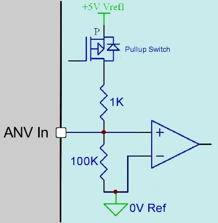
Analog input 7-12 with switchable 1 kΩ pull-up to 5.0 V Vref1 (for thermistors), or ratiometric mode with the pull-up OFF.
1.3 Digital Inputs 1-14 used as analog input(s)
Digital Input channels 1-14 are primarily used to measure frequency based signal and as switched inputs. However, the analog voltage on each digital input is also measured so all digital inputs can support ratiometric and absolute 3-wire based sensors. The input range is extended to 0-20V, which means the effective resolution is 4 times less than Analog Inputs 1-16. For this reason, don’t connect engine critical sensors to these channels e.g. Manifold Pressure, Throttle Position, Pedal Position etc. Digital Input channels 1-14 should be used to measure an analog signal once all the dedicated Analog Inputs 1-16/24 have been allocated.
Digital Analog Inputs 1-8 Summary
- Accepts a 0.0 - 20.0V analog input. Resolution is 4.88mV (10-Bit)
- Switchable 4k7 pull-up resistor to 8.8V on all 8 channels
- Input Impedance 39k Ohms to ground
- Over and under voltage protection
Digital Analog Inputs 9-14 Summary
- Accepts a 0.0 - 20.0V analog input. Resolution is 19.61mV (8-Bit)
- Switchable 4k7 pull-up resistor to 9.4V on all 6 channels
- Input Impedance 70k Ohms to ground
1.4 Sensor 0V Reference Pin(s)
These pins are NOT ECU grounds. Although a multi-meter test will show continuity to the ECU ground, these pins are designed as a low current 0V reference for pressure, position and temperature sensors. The following rules MUST always be observed:
- DO NOT connect these pins to the ECU main ground location(s). This is a specialised ground reference for all analog sensors and should be connected directly to the sensor 0V (ground) pin.
- DO NOT connect frequency-based sensor grounds to the 0V Reference pin; for example, an Ethanol content sensor. Use the main ECU ground.
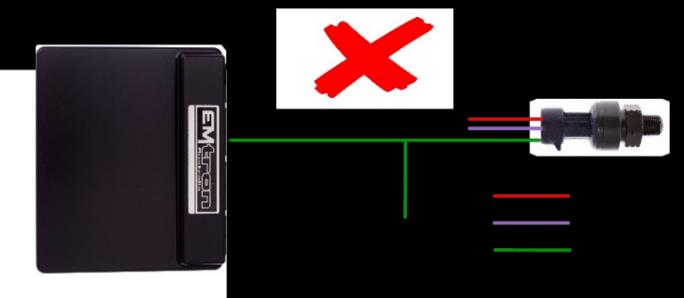
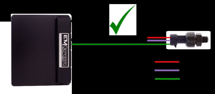
Incorrect — the 0V Reference must not be branched or shared with another ground point. Incorrect — do not daisy-chain the 0V Reference or tie it to the main ECU/engine ground. Correct — the 0V Reference is wired directly to the sensor’s 0V pin only.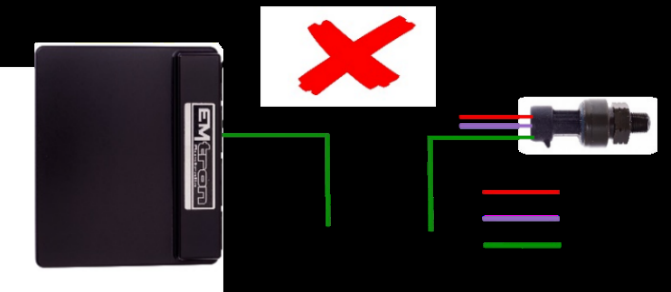
1.5 Analog Input configuration example
Table 1.0 shows a typical analog input assignment on a Drive by Wire (DBW) application.
Table 1.0. Analog Channel 1-16 assignment example.
| Channel | Input Pin |
|---|---|
| Manifold Pressure | Analog Voltage 1 |
| Boost Pressure | Analog Voltage 2 |
| DBW1 Servo Position Main | Analog Voltage 3 |
| DBW1 Servo Position Sub | Analog Voltage 4 |
| Mass Air Flow Meter 1 | Analog Voltage 5 |
| Engine Temperature | Analog Voltage 7 (Pull-up Channel) |
| Inlet Temperature | Analog Voltage 8 (Pull-up Channel) |
| Engine Oil Temperature | Analog Voltage 9 (Pull-up Channel) |
| Gearbox Oil Temperature | Analog Voltage 10 (Pull-up Channel) |
| Fuel Temperature | Analog Voltage 11 (Pull-up Channel) |
| Engine Oil Pressure | Analog Voltage 12 (Pull-up Channel) |
| Fuel Pressure | Analog Voltage 13 |
| Gear Detection Voltage | Analog Voltage 14 |
| Pedal Position Sensor 1 | Analog Voltage 15 |
| Pedal Position Sensor 2 | Analog Voltage 16 |
2.0 Digital Inputs
Digital Inputs 1-14 provide frequency and switched based inputs into the ECU. These inputs have a high level of configurability allowing easy interface to all sensor types. Digital Inputs 1-8 can be used to measure frequency, while all channels can accept a switched input. The analog voltage on all 14 channels is measured and can be used for diagnostics or ratiometric sensor interface.
2.1 Digital Input Channels 1-8 – Frequency
- Frequency range from 0.0Hz up to 30.0kHz on all 8 channels
- Magnetic and hall/optical effect sensor compatible with programmable trigger edge(s); rising, falling and both.
- Independent programmable frequency-based arming threshold control, range 0.0 - 12.0V
- Wheel speed, output shaft speed, turbo speed and other frequency-based signals
- VVT position(s) up to 4 channels available on DI 1-4.
- Switchable 4k7 ohm pull-up resistors on all 8 channels to 8.8V
- Filter time constant = 20us
- Maximum/Minimum input signal amplitude +/- 80V
- Input Impedance 39k Ohms to ground.
- Switch Input: Switch to 0V, Switch to VBatt, logic signal
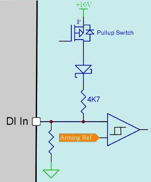
Digital frequency input — switchable 4k7 pull-up, protection clamp and zero-crossing comparator stage.
NOTE
- ONLY Digital Inputs 1-4 can be used to measure Cam Position(s) for VVT control.
- The ECU uses “True” zero crossing detection on magnetic based signals. This gives precise 0V crossing detection, critical on magnetic sensors used in VVT control.
- Emtron Scope function is available on Digital Inputs 1-4.
2.11 Arming Threshold Control – Magnetic Sensors
Arming threshold control is primarily used in zero crossing detection of magnetic based signals. The zero crossing circuitry cannot be triggered until the input signal has crossed an “arming” threshold on the positive-going (rising edge) portion of the waveform. Until this happens the zero crossing circuitry is OFF and all zero crossings will be ignored. Once the input signal has exceeded the arming threshold, the zero crossing circuitry is now ready (armed) and waiting for the zero crossing.
The arming threshold values will need adjusting as the signal frequency increases. i.e. signal amplitude is proportional to frequency until the sensor reaches saturation. For this reason, frequency-based signal should use a 2D tables for arming threshold control.
Below is a scope trace showing a signal over one cycle, scaled at 2V/Div. A conventional oscilloscope or the Emtron scope can be used to view a signal to best determine the correct arming thresholds. The preferred method is to find the lowest amplitude during one cycle (highlighted by the red circle below) and make the arming threshold 60% of that value. In this example the lowest value is 1.9V. Taking 60% gives an arming threshold of 1.1V.
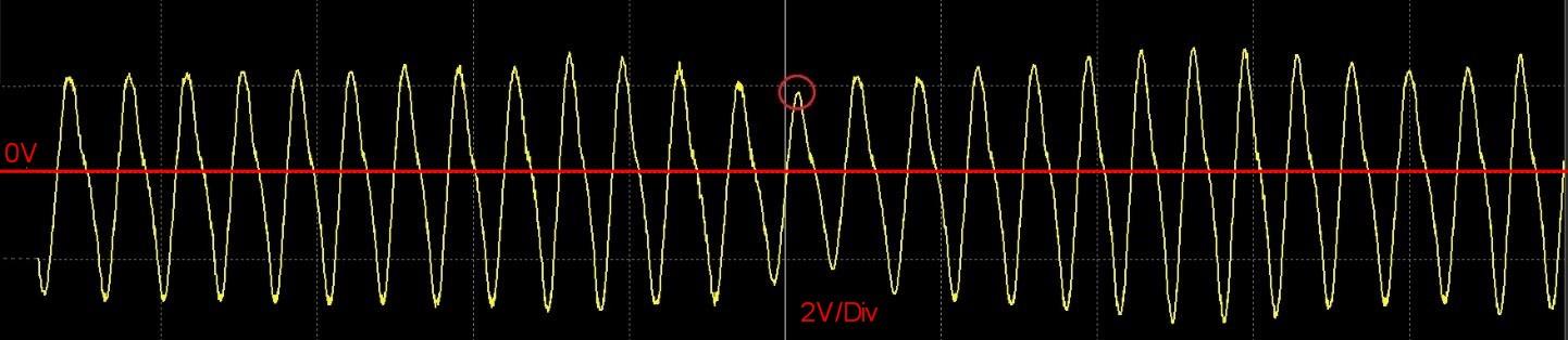
Oscilloscope capture of a magnetic sensor signal (2 V/Div). The red circle marks the lowest amplitude point used to calculate the arming threshold (60% of 1.9 V = 1.1 V).
In summary when the positive-going input exceeds 1.1V, the zero crossing circuitry becomes armed and is ready to detect the zero crossing on the next falling edge.
2.2 Digital Input Channels 1-14 – Switched Input
Digital Input channels 9-14 are for non-frequency based signal such as switched inputs, while Digital Inputs 1-8 are available for both. The status of a switched input (On/Off) is controlled by measuring the analog input voltage and comparing against user defined On threshold and user defined Off threshold. A switched input can supply either a ground or voltage into the ECU.
- Accepts a 0.0 - 20.0V analog input.
- Effective resolution DI 1-8 is 4.88mV (10-Bit)
- Effective resolution DI 9-14 is 19.61mV (8-Bit)
- Switch to 0V, Switch to VBatt, logic signal
- On/Off switched inputs: AC request, launch enable, cruise switch, table control switching etc with programmable switch-based arming threshold control, range 0.0 - 20.0V
- Switchable 4k7 ohm pull-up resistors on all 14 channels.
- Over and under voltage protection.
- Input Impedance DI1-8, 39k ohms to ground
- Input Impedance DI9-14, 70k ohms to ground
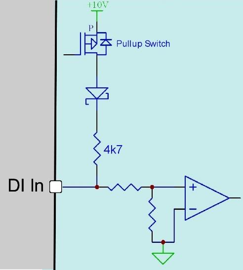
Switched input stage with switchable 4k7 pull-up and comparator.
Switch to Ground
In the case of a switch supplying a ground, the pullup resistor needs to be turned ON. With the switch in the OFF position, the ECU input will read the voltage supplied by the pullup resistor. With the switch in the ON position, the pullup resistor voltage is pulled to ground and the ECU input will read close to 0V.
NOTE: The current is limited by the 4k7 resistor so pulling the input to ground using the switch will not damage the ECU.
The current can be worked out using Ohms Law: V = I x R. Measure the voltage at the pin with the switch OFF, typically around 9V. Resistor = 4700 Ohm. Current (I) = 9V / 4700 = 1.9mA
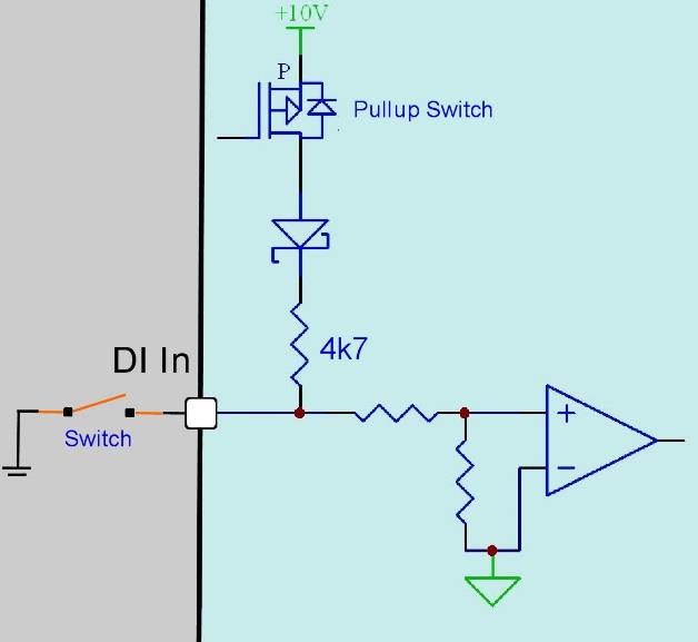
Switch to Ground — pull-up switched ON; the switch pulls the input to 0V.
Switch to Power
In the case of a switch supplying power, the pullup resistor needs to be turned OFF. With the switch in the OFF position, the ECU input will read the 0V through the internal pulldown resistor network. With the switch in the ON position, the switch voltage is fed into the ECU input.
NOTE: The ECU input is protected against high voltage up to +80V. Feeding the battery voltage into an input will not damage the ECU.
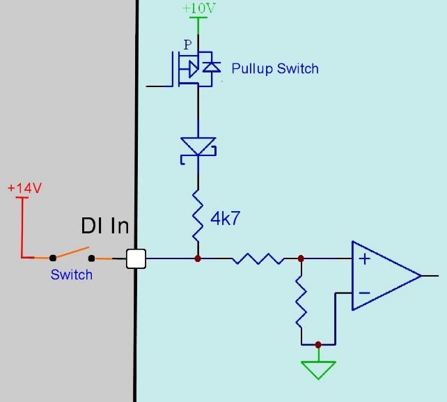
Switch to Power — pull-up switched OFF; the switch feeds voltage into the protected input.
2.3 Digital Input Channels 1-14 – Analog Input
When not used as frequency or switched inputs these channels can be used to measure analog signals for ratiometric and absolute 3-wire based sensors. Refer back to Section 1.3.
2.4 Digital Input configuration example
Table 2.0 shows a Digital Input engine configuration example for both Non-VVT and VVT applications.
Table 2.0. Digital Input engine configuration example
| DI Input Pin | Channel (non VVT) | Channel (VVT) |
|---|---|---|
| Digital Input 1 | Speed Rear LH | Intake LH Cam Position |
| Digital Input 2 | Speed Rear RH | Intake RH Cam Position |
| Digital Input 3 | Power Steer switch | Exhaust LH Cam Position |
| Digital Input 4 | Start Switch | Exhaust RH Cam Position |
| Digital Input 5 | Clutch Switch | Speed Front LH |
| Digital Input 6 | Turbo Speed | Speed Front RH |
| Digital Input 7 | Launch Enable Switch | Speed Rear LH |
| Digital Input 8 | Fuel Used Reset Switch | Speed Rear RH |
| Digital Input 9 | Rotary Switch | Clutch Switch |
| Digital Input 10 | AC switch | Start Switch |
| Digital Input 11 | Launch Enable Switch | |
| Digital Input 12 | Fuel Used Reset Switch | |
| Digital Input 13 | AC switch | |
| Digital Input 14 | Rotary Switch |
3.0 Auxiliary Outputs
The ECU has 16 Auxiliary Outputs with a wide variety of driver types to suit all applications. These drives are suitable for controlling relays, resistive and inductive loads, stepper motors, DC servo motors and electronic throttles. All outputs are short circuit and over current protected.
3.1 Auxiliary Output 1-8 – Low side or High side
Auxiliary 1-8 drivers can be configured as Off, Low side or High side driving. Low side refers to an open collector output that switches to ground. A High side driver refers to an output that switches to the ECU Supply voltage.
- Auxiliary 1-8 drivers can be configured for Low side or High side driving
- Maximum frequency 15kHz
- Flywheel diode integrated into all outputs with recirculation current to the ECU Supply pin D1
- Pin voltage monitored for diagnostics
- Over current / Short to Battery / Thermal overload protection
- Electrostatic discharge (ESD) protection
- Reverse battery protection
Low Side Drivers
- Auxiliary 1-4: Low side 4A continuous, 8A limit
- Auxiliary 5-8: Low side 2.5A continuous, 5A limit
High Side Drivers
- Power sourced from the ECU Supply pin
- Auxiliary 1-8: High side 4A continuous, 9A limit
Suitable applications
- High frequency solenoids used in Variable Valve Timing (VVT), Variable Valve Timing Electric (VTiE), Idle Speed Control
- Low frequency solenoids used in boost control, gearshift solenoids, stepper motor and many more
- Solenoid and relay switching used in cam switching (VTEC), runner length control and basic fuel pump, fan and AC relay control.
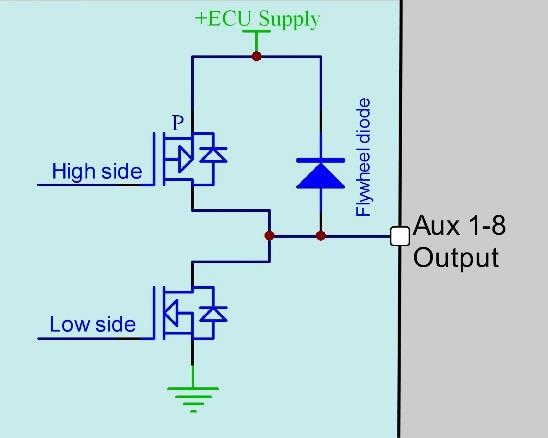
Auxiliary 1-8 output stage — selectable high-side / low-side driver with integrated flywheel diode to the ECU Supply.
3.2 Auxiliary Output 9-12 – Half Bridge
Half bridge drivers supply either a ground or battery voltage i.e. there is no “off” state. Auxiliary outputs 9-12 are medium power half bridge drivers, primarily used for DBW control. Auxiliary 9/10 can be paired into H-bridge configuration for DBW 1 control and Auxiliary 11/12 can be paired into H-bridge configuration for DBW 2 control.
- Driver IC for Aux9-12 needs power using “Aux 9-12 Supply” pin D20. In non-DBW applications the ECU Supply power source can be used. In DBW applications power to this pin MUST come from an ECU controlled DBW Relay.
- Maximum frequency 15 kHz
- Flywheel diode integrated into all outputs with recirculation current to the Aux 9-12 Supply pin D20
- Over current / Short to Battery / Thermal overload protection
- Electrostatic discharge (ESD) protection
- Reverse battery protection
- Half Bridge 5A continuous and 8A limit. Can be used as Low Side, High Side or paired with another channel for DC motor control (DBW)
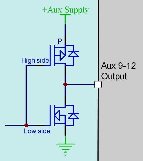
Auxiliary 9-12 medium-power half-bridge driver (high-side / low-side), powered from the Aux 9-12 Supply.
3.3 Auxiliary Output 13-16 – Half Bridge
Half bridge drivers supply either a ground or battery voltage i.e. there is no “off” state. These are high power half bridge drivers used to switch high current inductive loads. In a KV12 and KV16 they can also be paired for DBW control giving a total of 4 DBW channels.
- Driver ICs for Aux13-16 needs power using “Aux 13-16 Supply” pin D2. In non-DBW applications the ECU Supply power source can be used. In DBW applications power to this pin MUST come from an ECU controlled DBW Relay.
- Maximum frequency 15 kHz
- Flywheel diode integrated into all outputs with recirculation current to the Aux 13-16 Supply pin D2
- Over current / Short to Battery / Thermal overload protection
- Electrostatic discharge (ESD) protection
- Reverse battery protection
- Half Bridge 15.0A continuous (pin limited). Can be used as Low Side, High Side or paired with another channel for DC motor control (DBW)
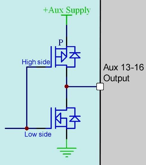
Auxiliary 13-16 high-power half-bridge driver, powered from the Aux 13-16 Supply.
3.4 Auxiliary Outputs – Full Bridge Configuration (DBW)
By connecting 2x half bridge outputs together a full bridge can be configured. This is used for DC motor direction and braking control required for applications like DBW control. The below schematic shows Aux 9 and 10 paired to form a full bridge configuration for DBW control.
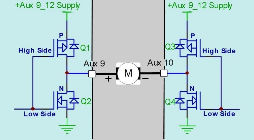
Full bridge (H-bridge) formed by pairing Aux 9 and Aux 10 for DBW motor direction and braking control.
The following table 3.0 explains the operation for the full bridge.
Table 3.0. Full Bridge operation
| Transistor Q1 | Transistor Q2 | Transistor Q3 | Transistor Q4 | DBW/Motor Direction | Aux 9 Output | Aux 10 Output |
|---|---|---|---|---|---|---|
| ON | OFF | OFF | ON | Forward | H | L |
| OFF | ON | ON | OFF | Reverse | L | H |
| ON | OFF | ON | OFF | High side Freewheeling | H | H |
| OFF | ON | ON | OFF | Low Side Freewheeling | L | L |
For 1 or 2 channels DBW applications the following output pairing is required:
- DBW1, it is recommended to pair Auxiliary 9 and Auxiliary 10 outputs.
- DBW2, it is recommended to pair Auxiliary 11 and Auxiliary 12 outputs.
For KV12 and KV16, 4 channel DBW applications the following output pairing is required:
- DBW3, it is recommended to pair Auxiliary 13 and Auxiliary 14 outputs.
- DBW4, it is recommended to pair Auxiliary 15 and Auxiliary 16 outputs.
3.5 Auxiliary Output – Flywheel diodes
Flywheel diodes are used to eliminate the voltage spike or flyback voltage when an inductive load is switched off. The diode recirculates the inductive energy at switch off, so it can be dissipated by the internal resistance of the load. This schematic shows the Low side driver switching off; the red arrows indicate how the current recirculates through the flywheel diode and back through the load. The current will decay until it’s insufficient to keep the load On or solenoid open, at which point the load will turn Off.
Note: The ECU and load share the same power supply allowing the flywheeling to operate.
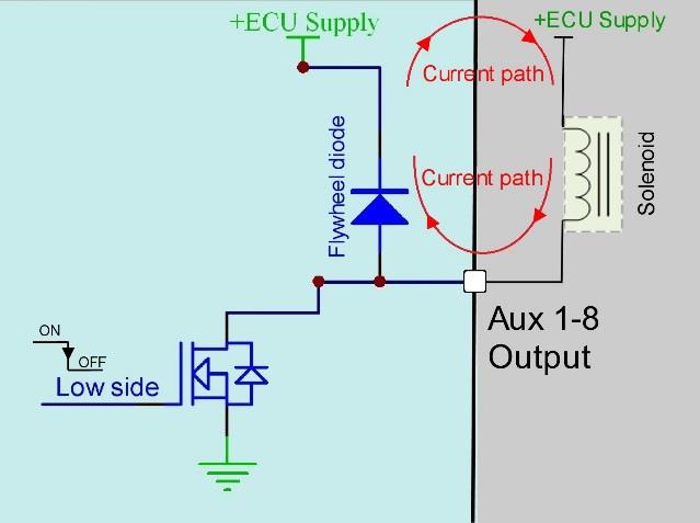
Low-side driver with integrated flywheel diode. The red arrows show the current recirculation path when the driver turns off.
Important points
- Flywheel diodes allow inductive energy to be dissipated back into the load
- Flywheel diodes will increase the time it takes for the load to switch off
- Flywheel diodes minimize EMI by removing the inductive voltage spike and forcing the current to recirculate. The higher the frequency the more important this is.
3.51 VVT and Idle Solenoids – why we need flywheel diodes
When controlling VVT solenoids flywheel diodes are required for the solenoid to operate correctly. At frequencies between 200Hz - 300Hz, the flywheel diode prevents the solenoid switching fully On or fully Off. The flywheel diode allows the current to recirculate and find an “average” value during the switch On and switch Off times (duty cycle). Instead of the solenoid switching fully On or fully Off we can control its position between these 2 points. By controlling the duty cycle, the solenoid average position can be controlled.
For this reason, Auxiliary channel 1-16 are recommended for VVT/Idle solenoid control. If however a Fuel or Ignition channel is used an external flywheel MUST be fitted.
3.52 Boost Control Solenoid
These solenoids require a fast reduction in current when switched off. As all Auxiliary channels have integrated flywheel diodes this recirculation circuitry slows the switch off time at higher frequencies and will cause solenoid control issues. For this reason, the boost control modulation frequency should be kept below 30Hz. Typical values are 15 – 20Hz.
3.53 Transmission Brake Solenoid
Some Transmission Brake solenoids produce a large amount of energy when released. Auxiliary channels 13-16 are the only outputs with enough current to power such solenoids. It is strongly recommended to run an external flywheel diode to prevent long term ECU damage. If the output is modulated a flywheel diode MUST be installed (See Emtron www for details).
NOTE: Maximum Trans-brake frequency is 100Hz
3.6 Permanently Powered Loads
Auxiliary outputs 1-8 are not suitable for permanently powered loads. The integrated flywheel diode will cause back-feeding onto the flywheel recirculation pin (ECU Power pin) and keep the ECU powered up. This can be viewed using the schematic below. With the Low and High side drivers off, current will flow through the solenoid, through the flywheel diode and back onto the ECU supply. To avoid this issue, move the load to a non-flywheel output such as an unused Fuel or Ignition channel or re-configure the solenoid supply feed.
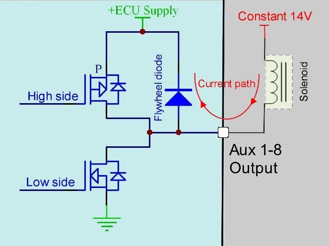
A permanently powered load on an Aux 1-8 output back-feeds through the flywheel diode onto the ECU supply, keeping the ECU powered up.
3.7 Auxiliary Output configuration example
Table 3.1 shows an Auxiliary output engine configuration example for both Non-VVT and VVT applications.
Table 3.1. Auxiliary Output engine configuration example
| Aux Output Pin | Channel (non VVT) | Channel (VVT) |
|---|---|---|
| Auxiliary 1 | Idle Solenoid | VVT Intake LH Solenoid |
| Auxiliary 2 | Boost Solenoid | VVT Intake RH Solenoid |
| Auxiliary 3 | Tacho | VVT Exhaust LH Solenoid |
| Auxiliary 4 | Fuel Pump | VVT Exhaust RH Solenoid |
| Auxiliary 5 | Fuel Pump Speed | Cooling Fan |
| Auxiliary 6 | AC Clutch | Boost Solenoid |
| Auxiliary 7 | Cooling Fan | Tacho |
| Auxiliary 8 | Cam Switch | Fuel Pump |
| Auxiliary 9 | AC Fan | DBW 1+ |
| Auxiliary 10 | CEL | DBW 1- |
| Auxiliary 11 | Downshift Solenoid | |
| Auxiliary 12 | Upshift Solenoid | |
| Auxiliary 13 | AC Fan | |
| Auxiliary 14 | CEL | |
| Auxiliary 15 | AC Clutch | |
| Auxiliary 16 | DBW Relay |
4.0 Injector Outputs
The KV series supports from 8 up to 16 injector outputs and will control both modes of injection; Saturated and Peak and Hold.
| KV ECU | Injector Outputs |
|---|---|
| KV8 | 8 |
| KV12 | 12 |
| KV16 | 16 |
| KV16M | 16 |
4.1 Injector Control
Precise and consistent control is also gained with a high 70V flyback voltage, allowing for rapid current reduction at switch Off time.
- Flyback Voltage Clamp 70V
- Total current limited to 10A
- Outputs can be used for ground switching, 6A Continuous, 10A Limit
- All outputs are short circuit and over current protected
- Pin voltage monitored for diagnostics
- No Flywheel diodes (external diode(s) required for VVT and Idle Speed control)
- Suitable to connect loads that are permanently powered
4.11 Peak and Hold Injector Control
When using low impedance injectors (< 5 Ohms) the ECU uses a switch mode current limiting technique to minimise heat dissipation in the Injector. This gives better injector control and helps maximize injector life by lowering its operating temperature. Switched Flywheel circuitry is used to recirculate injector current back to the ECU supply during the “Hold” phase. This is ONLY active in Peak and Hold mode.
- Independently configurable Peak and Hold currents up to 16 cylinders
- Flyback Voltage Clamp 70V
- Max Peak current 8A
- Max Hold current 4A
- Total current limited to 10A
- Flywheel recirculation current to the ECU Supply pin D1 during “Hold” phase.
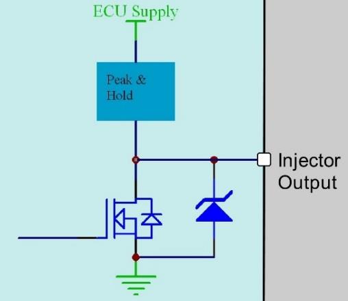
Peak and Hold injector driver with switched flywheel recirculation to the ECU Supply during the Hold phase.
4.2 Saturated Injector Control
Required when injector resistance is greater than 5 Ohms
- Flyback Voltage Clamp 70V
- Total current limited to 10A
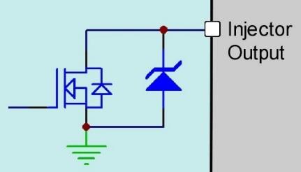
Saturated injector driver with 70 V flyback voltage clamp.
4.3 Auxiliary Load Switching on Injector Outputs
When the Injector output is not configured to drive an injector, it can be used to switch or modulate a resistive or inductive load. i.e. relay, waterspray solenoid, Boost solenoid etc.
- Flyback Voltage Clamp 70V
- Total current limited to 10A
- Maximum Frequency 5kHz
- No internal flywheel diodes. VVT and Idle solenoids require external flywheel diodes
4.4 Protection
- Over current / Short to Battery protection
- Electrostatic discharge (ESD) protection
- Flyback Voltage Clamp 70V
5.0 Ignition Outputs
The KV series supports from 8 up to 12 Ignition channels with logic level outputs.
| KV ECU | Ignition Outputs |
|---|---|
| KV8 | 8 |
| KV12 | 12 |
| KV16 | 12 |
| KV16M | 12 |
5.1 Ignition Control
When configured for ignition, these outputs are logic level drivers, capable of sourcing current in the range of 35 - 70mA. DO NOT connect directly to a coil and attempt to drive it. An ignitor MUST be used between the ECU and coil.
- Open collector output (low side) with active current source control to produce a logic level signal for Ignitor control.
- Adjustable Ignition drive current (35mA or 70mA global control). For example, more current is required when 1 output is driving 2 ignitors.
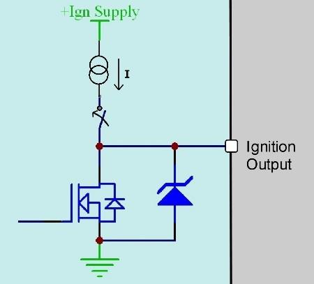
Logic-level ignition output driver — open collector with active current source for ignitor control.
5.2 Auxiliary Load Switching on Ignition Outputs
When the Ignition output is not configured to drive an ignitor, it can be used to switch or modulate a resistive or inductive load. i.e. relay, waterspray solenoid, Boost solenoid etc.
- Open collector outputs (low side) with current source is OFF.
- Flyback Voltage Clamp 40V
- Continuous current limited to 1A
- Total current limited to 3A
- Maximum Frequency 5kHz
- No internal flywheel diodes. VVT and Idle solenoids require external flywheel diodes
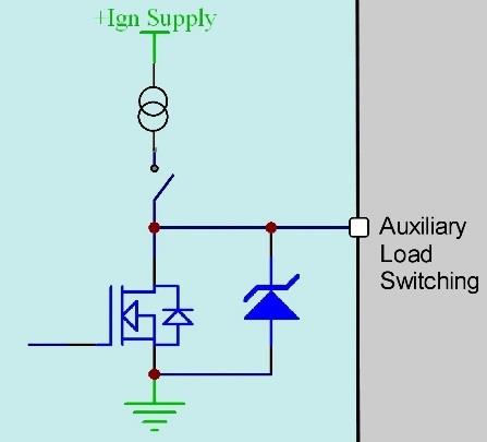
Ignition output used for auxiliary load switching (current source OFF, 40 V flyback clamp).
5.3 Protection
- Over current / Short to Battery protection
- Electrostatic discharge (ESD) protection
- Flyback Voltage Clamp 40V
6.0 Crank Index and Sync Sensor Inputs
The KV series supports a Crank Index and Sync position inputs.
- Magnetic and hall/optical effect sensor compatible with programmable trigger edge(s); rising, falling and both.
- “True” zero crossing detection on magnetic signals for precise engine position decoding
- Independent programmable arming threshold control, range 0.0 - 12.0V
- Switchable 4k7 ohm pull-up to 5.0V
- Maximum/Minimum input signal amplitude +/- 80V
- Input Impedance 39k Ohms to ground
- OEM patterns supported
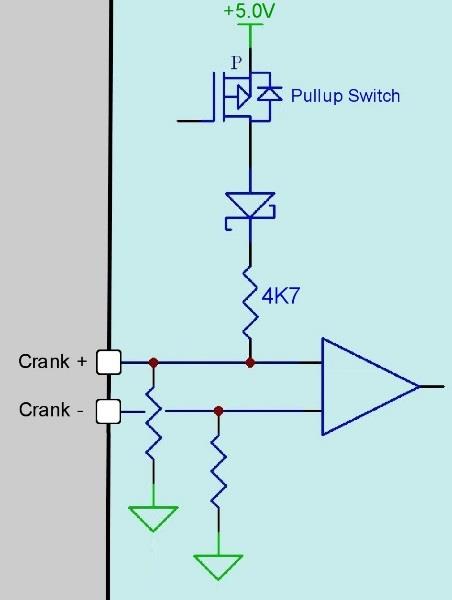
Crank Index / Sync magnetic input with switchable pull-up and true zero-crossing detection.
For the maximum noise immunity and best possible signal to noise ratio both positive ("+") and negative ("-") inputs should be connected directly to the sensor. DO NOT connect a Crank or Cam sensor negative to the ECU ground or engine block, instead use the dedicated negative inputs supplied by the ECU.
NOTE
- Emtron Scope function is available on both Crank Index and Sync inputs.
- For more information on Arming Thresholds, refer back to section 2.11.
7.0 Knock Control
- 2x Independent knock input channels
- Fully differential inputs for each channel
- Bosch knock integrated circuit technology using advanced digital signal processing
- Programmable FIR-filter
- Selectable center frequency from 500Hz - 25kHz
- Selectable bandwidth from 100Hz - 5kHz
- Selectable Digital Filter Window; Hamming or Blackman
- Gain Control (1x, 2x, 4x, 8x)
- Input anti-aliasing Low pass filter
- Cylinder selectable Knock input
- Individual cylinder Knock control available on ALL Ignition modes with a 720 sync (Direct, Wasted, Distributor etc)
- Diagnostics available for each pin (includes shorted inputs)
8.0 Lambda Control
The ECU supports on-board dual Lambda controllers using the Bosch LSU4.9 wide band oxygen sensor. The ECU uses Bosch integrated and amplifier control circuitry to give precise sensor control and performs three primary functions:
- Measurement of oxygen concentration
- Sensor temperature for heater control.
- Diagnostics of sensor wiring.
The stability of the LSU4.9 Sensor temperature is critical because measurement of oxygen concentration is temperature sensitive. The ECU uses an advanced control system to measure the internal resistance of the Nernst cell and generate dynamic PID heater and temperature control.
Lambda LSU4.9 Summary
- 2x Independent on-board lambda channels supporting the Bosch LSU 4.9 sensor
- Using Bosch integrated circuit technology for precise sensor control
- Nernst cell temperature measurement for dynamic PID closed loop heater and temperature control
- Lambda range: 0.580 La to 10.000 La
- Diagnostics available for each pin includes, Short to ground, Short to Vbatt, Open Load.
9.0 Supply Voltage Inputs
9.1 ECU Supply
The ECUs use a “smart” transient protection system to protect itself from damage against high voltage transients. It constantly monitors the ECU supply voltage and if it exceeds 24V a transient protection system activates and begins limiting/regulating the internal ECU supply at 24V. This effectively clamps the ECU supply protecting it in the short term. Due to the large currents involved, the transient protection system cannot clamp the voltage at 24V indefinitely. After 1 second, if the ECU supply has not returned to less than 24V the transient protection system shuts the power down and the ECU will switch off. The figure below illustrates the operation of the transient protection system by showing the input 300ms transient event vs output characteristics.
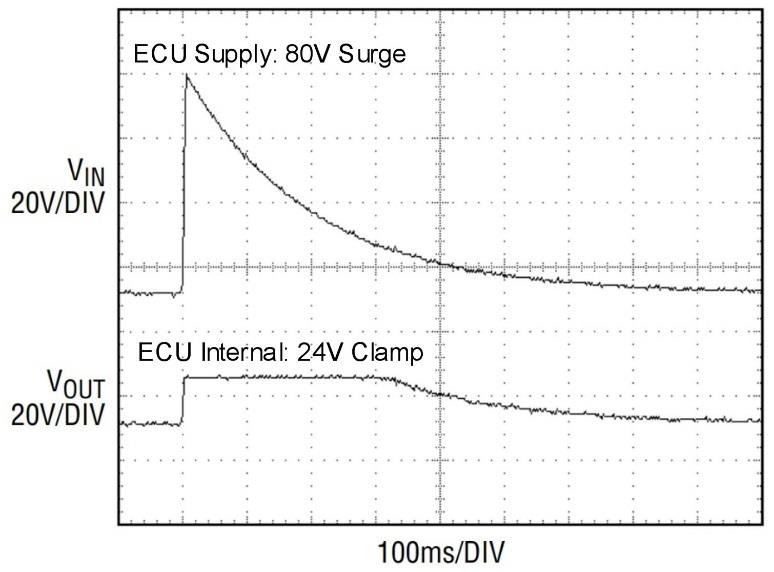
“Smart” transient protection behaviour — input voltage surge (80 V) vs the clamped 24 V internal output during a 300 ms event.
- Operating voltage: 6.0 to 22.0 Volts DC (ECU shutdowns at 24.0V)
- Typical operating current: 390mA at 14.0V (excluding sensor and load currents)
- Reverse battery protection via external fuse
- “Smart” battery transient protection
- 15.0A Max (pin limited)
- Power supply for Auxiliary Channels 1-8 High Side Drivers
- Flywheel supply for Injector channels when Peak & Hold mode is active
- Flywheel supply for Auxiliary channels 1-8
9.2 Aux 9-12 Supply
This is a dedicated power supply for Auxiliary Channels 9-12 half bridge drivers. Power must be supplied to this pin for these channels to operate correctly. In non-DBW (Drive by Wire) applications the ECU Supply power can be shared, assuming the wire gauge has a sufficient rating for the current demand. In DBW applications power to this pin MUST come from an ECU controlled DBW Relay. See the KV Series Power Distribution Wiring for more information on how this should be wired.
- 15.0A Max (pin limited)
9.3 Aux 13-16 Supply
This is a dedicated power supply for Auxiliary Channels 13-16. Power must be supplied to this pin for these Auxiliary channels to operate correctly. In non-DBW (Drive by Wire) applications the ECU Supply power can be shared, assuming the wire gauge has a sufficient rating for the current demand. In 4 channel DBW applications power to this pin MUST come from an ECU controlled DBW Relay.
- 15.0A Max (pin limited)
10.0 Regulated Voltage Outputs
The KV series regulated supplies are designed for the harsh automotive environment. They include protection from reverse battery, jump starting transient voltage surges and automatic shutdown when the output is shorted to ground.
5.0V VRef1
- Main sensor 5.0V supply
- Continuous current 0.4 Amps
- Accuracy: +/- 1.0% at 25 °C (10mV/V)
- Short circuit, Reverse battery protection, Thermal overload protection
- Operating temperature range -40°C ~ 125°C
5.0V VRef2
- Secondary sensor 5.0V supply
- Continuous current 0.4 Amps
- Accuracy: +/- 1.0% at 25 °C (10mV/V)
- Short circuit, Reverse battery protection, Thermal overload protection
- Operating temperature range -40°C ~ 125°C
8V VCAS
- Continuous current: 0.6 Amps
- Accuracy: +/- 1.0% at 25 °C
- Short circuit, Reverse battery protection, Thermal overload protection
- Operating temperature range -40°C ~ 125°C
11.0 EFI Relay Control
The ECU can control an EFI relay, allowing for management of its own power supply. To achieve this a dedicated Ignition Switch Input and EFI Relay Output are used. When 14V is applied to the Ignition Switch input, the ECU internal circuitry switches the EFI relay output On. This will provide a ground, turning the relay On and supplying power to the ECU. Once powered up the ECU takes control on this output. When the Ignition Switch turns Off the ECU can complete critical tasks before shutting itself down (for example, DBW Self calibration and ECU Logging data storage).
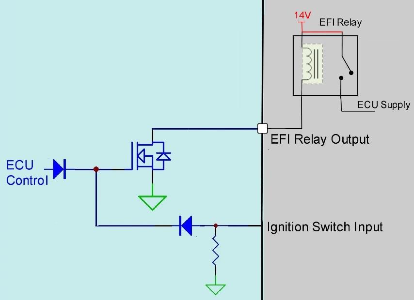
Dedicated EFI relay control circuit — the Ignition Switch input drives the EFI Relay Output (relay ground, 200 mA).
Dedicated EFI Relay Control
- Provides a relay ground, 200mA Limit
- Short circuit, thermal overload protection, reverse battery
Dedicated Ignition Switch
- Used to control Main EFI Relay circuit at key-on
- Input Analog Voltage Range: 0 - 20.0V
- Input Impedance 100k Ohms to ground
- Adjustable On/Off software thresholds. Resolution = 0.1V
SL4 ECU Datasheet
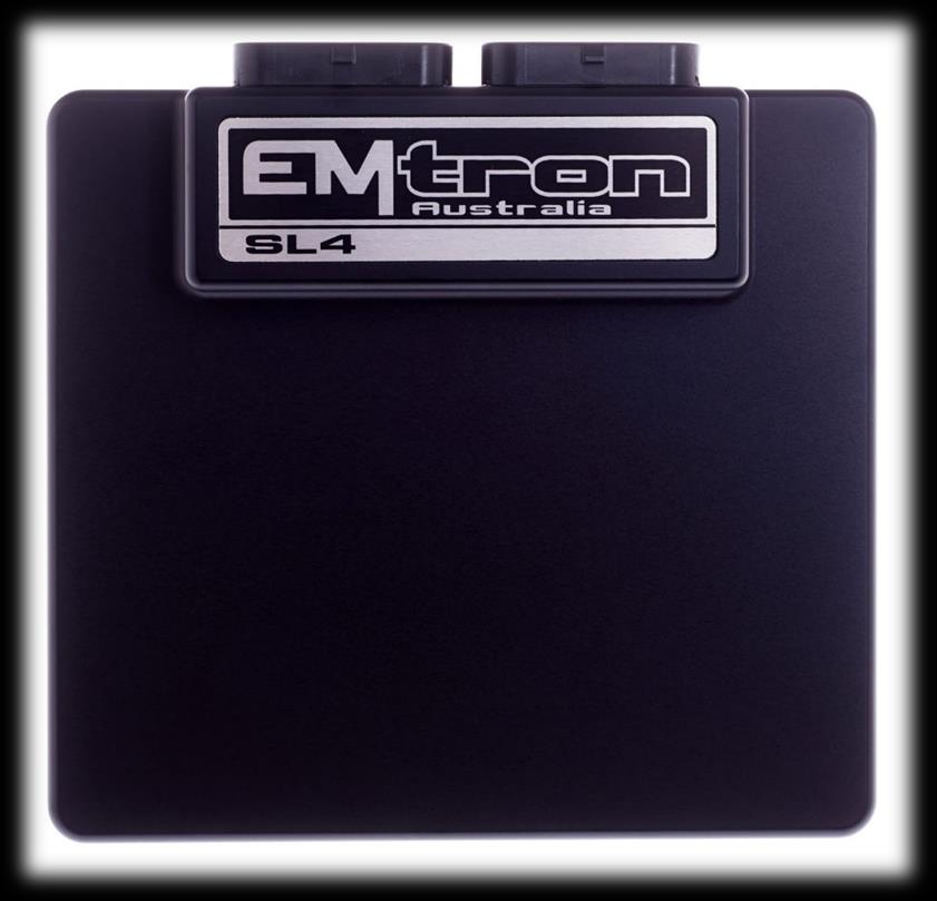
Emtron SL4 ECU
1.0 General
Emtron’s SL Series is built upon the outstanding foundation of the KV Series and features the same processing power and logging capacity. This lightweight package is housed in a Billet Aluminium Enclosure and features a 68-pin connector system which is still a very high I/O count. The SL4 ECU will support up to 4 Channels of fully sequential Fuel and Ignition. Up to 32MB permanent memory for on-board logging is available, 4-channel oscilloscope function, DBW control, Knock control using digital filter technology, High Speed Ethernet communications and 3-axis G-force sensing to name a few.
Power Supply
- Operating voltage: 6.0 to 22.0 Volts DC (ECU shutdowns at 24.0V)
- Operating current: 290mA at 14.0V (excluding sensor and load currents)
- Reverse battery protection via external fuse
- “Smart” battery transient protection
Operating Temperature
- Max operating range: -30 to 110°C (-22 to 230°F)
- Recommended operating range: -30 to 85°C (-22 to 185°F)
Physical
- Aluminium 6061 grade CNC billet enclosure
- Enclosure size 120 mm x 130 mm x 27 mm
- Weight: 470g
- Connector system: 68-way Super Seal waterproof connectors with gold plated contacts
- Pin diameter: 1 mm
- Current rating: maximum 15A per pin (wire gauge dependant)
- Connector A: 34 pin Key 2 Super Seal
- Connector B: 34 pin Key 1 Super Seal
Internal
- Dual 100MHz processors
- 500Mb DDR RAM (0.5Gb)
- 32MB ECU logging memory
- Over 1200 channels available
- 1Hz to 500Hz logging rate
- Oscilloscope 4-channel function with 32MB storage
- Sampling at 100k samples/second
- Includes Crank Index and Sync sensor inputs
- Includes Digital Inputs 1-4
- On-Board barometric pressure sensor
- Range 40 - 115.0 kPa
- 3-Axis accelerometer
- 16-Bit resolution
- +2g/+4g/+8g dynamically selectable full-scale
- Output data rate 500Hz
2.0 Outputs
4x Port Injector Outputs — high ohm
- 70V clamping
- Outputs can be used for ground switching, 6A Continuous, 10A Limit
- All outputs are short circuit and over current protected
- No Flywheel diodes (external diode(s) required for VVT control)
4x Ignition Outputs
- Adjustable TTL Ignition drive current (35mA or 70mA)
- Outputs can be used for ground switching, 1A Continuous, 3A Limit
- All outputs are short circuit and over current protected
- No Flywheel diodes (external diode(s) required for VVT control)
10x Auxiliary Outputs
- Variable Valve Timing (VVT) and Variable Valve Timing Electric (VTiE), Drive by Wire (DBW), dual boost control, gearshift solenoids, stepper motor and many more.
- All outputs have PWM control, maximum frequency = 15 kHz
- Flywheel diodes integrated into all outputs
- Auxiliary 1-8 Flywheel to the “ECU Supply” pin B1 connector B
- Auxiliary 9-10 Flywheel to the “ECU 9-12 Supply” pin A34 connector A
- All outputs are short circuit and over current protected
Low Side Drivers
- Auxiliary 1-4: Low Side 4A continuous, 6A peak modulated, 8A limit
- Auxiliary 5-8: Low Side 2.5A continuous, 4A peak modulated, 5A limit
High Side Drivers
- Auxiliary 1-8: High Side 4A continuous, 9A limit
Half Bridge Drivers
- Auxiliary 9-10: Half Bridge 5A continuous and 8A limit. Can be used as Low Side, High Side or together in H-bridge configuration for DC motor control (DBW)
1x EFI Relay Output
- Low Side Driver for relay control. Current limited to 200mA (Output will switch ON when Ignition Switch Input (B4) is greater than 4V)
1x Shield Output
- Connection for Trigger and Knock shielded cables. Short to battery protection
3.0 Inputs
10x Analog Voltage/Temperature Inputs
- Fully configurable including custom calibrations
- Switchable 1k ohm pull-up resistors on ANV 7-10
- Accepts a 0.000 - 5.000V analog input. Resolution is 1.22mV (12-Bit)
- Input Impedance 100k Ohms to ground
6x Digital/Speed Inputs/Switched Inputs
- Frequency range from 0.0Hz up to 30.0kHz on all 6 channels
- Magnetic and Hall effect sensor compatible on DI 1-4 with programmable trigger edge(s)
- Hall effect sensor only on DI 5-6 with programmable trigger edge(s)
- Independent programmable frequency-based arming threshold control, range 0.0 - 12.0V on DI 1-4
- Fixed frequency-based arming thresholds on DI 5-6. Rising = 1.2V, Falling = 1.0V.
- Wheel speed, output shaft speed and other frequency-based signals
- VVT position(s) up to 4 channels available on DI 1-4.
- ON/OFF switched inputs: AC request, Launch enable, cruise switch, table control switching etc with arming threshold control, range 0.0 - 20.0V
- Accepts a 0.0 - 20.0V analog input. Resolution is 4.88mV (10-Bit)
- Switchable 4k7 ohm pull-up resistors on all 6 channels to 10V
- Maximum input signal amplitude +/- 80V
2x Knock Inputs with configurable Frequency and Gain
- Using Bosch digital knock integrated circuit technology
- Selectable center frequency from 500Hz - 25kHz
- Selectable bandwidth from 100Hz - 5kHz
- Selectable digital filter window; Hamming or Blackman
1x Dedicated Ignition Switch Input
- 6.0 - 20.0V input used for EFI Relay Control. (With input > 4V the EFI Relay output (D9) will switch ON)
2x Crank Index and Sync Engine Decoding Inputs
- Magnetic and Hall effect sensor compatible with programmable trigger edge(s)
- “True” zero crossing detection on magnetic signals for precise engine position decoding.
- Programmable independent arming threshold control from 0.1V to 12.0V
- Switchable 4k7 ohm pull-up resistor to 5V
- OEM patterns supported
- Maximum input signal amplitude +/- 80V
- Input Impedance 39k ohms to ground
4.0 Voltage and Ground Supplies
1x ECU Supply Input
- 15.0A Max (pin limited)
- 6V - 22.0V Range
- Supplies ECU power
- Supplies power to Auxiliary 1-8 High Side Drivers
1x Auxiliary 9-10 Supply Input
- 15.0A Max (pin limited)
- Power supply for Auxiliary channels 9-10. (See the SL Series Power Distribution Wiring for more information on how this should be wired. Also see Section 6.1)
1x 5.0V Sensor Supply
- 5V Vref1 output current 250mA
1x 8.0V Sensor Supply
- Output current 400mA
2x ECU Main Grounds
- 15.0A per pin, total 30A
1x Sensor 0V Reference
- Analog Sensor 0V Reference with short to battery protection (See note in Section 6.1)
NoteNOTE The Sensor 0V Reference pin(s) are specialised ground outputs for all analog sensors. Connect direct to the sensor 0V pin, DO NOT connect to the Engine Block or ECU Ground.
5.0 Communications
- 1x high speed Ethernet 100Mbps
- 1x CAN 2.0B 1Mbps / 6 Channels per node, total 64 messages.
6.0 SL4 Pinout
Connector A: Injection / Ignition / Auxiliary Outputs
(15.0A Max continuous current - wire gauge dependant)
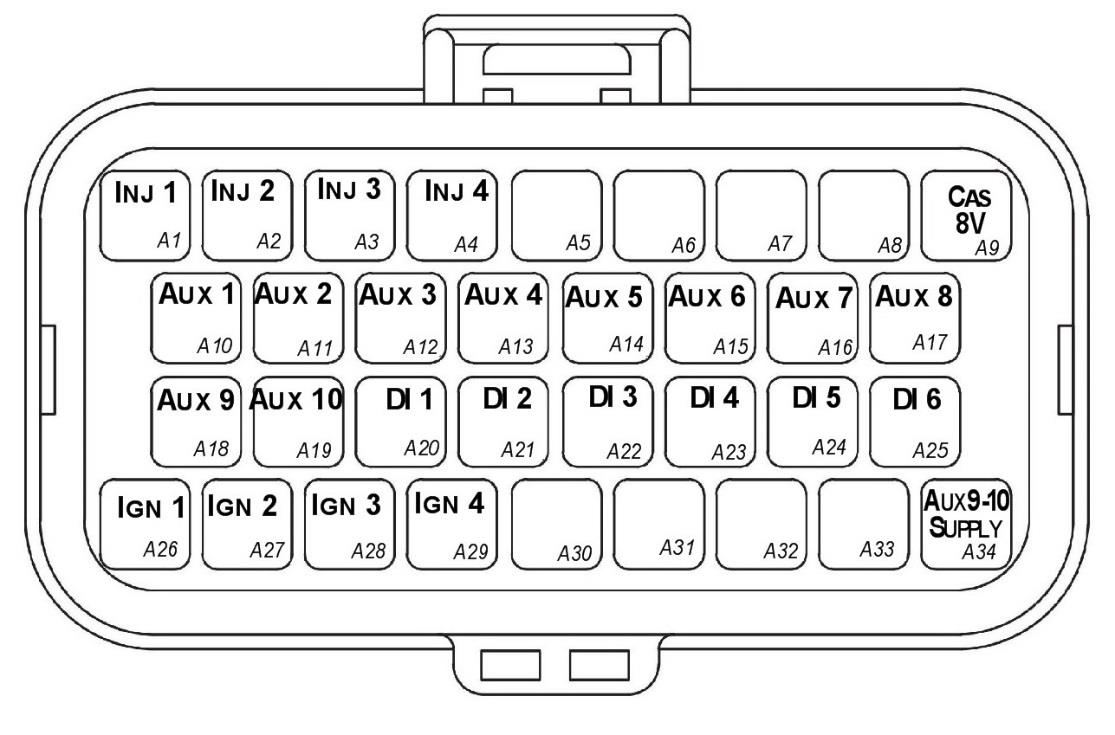
SL4 Connector A — looking into ECU connector.
| Pin | Channel Name | Pin | Channel Name |
|---|---|---|---|
| A1 | Injection Channel 1 | A18 | Auxiliary Output 9 |
| A2 | Injection Channel 2 | A19 | Auxiliary Output 10 |
| A3 | Injection Channel 3 | A20 | Digital Input 1 |
| A4 | Injection Channel 4 | A21 | Digital Input 2 |
| A5 | NC | A22 | Digital Input 3 |
| A6 | NC | A23 | Digital Input 4 |
| A7 | NC | A24 | Digital Input 5 |
| A8 | NC | A25 | Digital Input 6 |
| A9 | Sensor Supply 8V | A26 | Ignition Channel 1 |
| A10 | Auxiliary Output 1 | A27 | Ignition Channel 2 |
| A11 | Auxiliary Output 2 | A28 | Ignition Channel 3 |
| A12 | Auxiliary Output 3 | A29 | Ignition Channel 4 |
| A13 | Auxiliary Output 4 | A30 | NC |
| A14 | Auxiliary Output 5 | A31 | NC |
| A15 | Auxiliary Output 6 | A32 | NC |
| A16 | Auxiliary Output 7 | A33 | NC |
| A17 | Auxiliary Output 8 | A34 | Auxiliary Output 9-10, 14V Supply |
Connector B: Signal / Power / Communications / Triggers / Knock
(15.0A Max continuous current - wire gauge dependant)
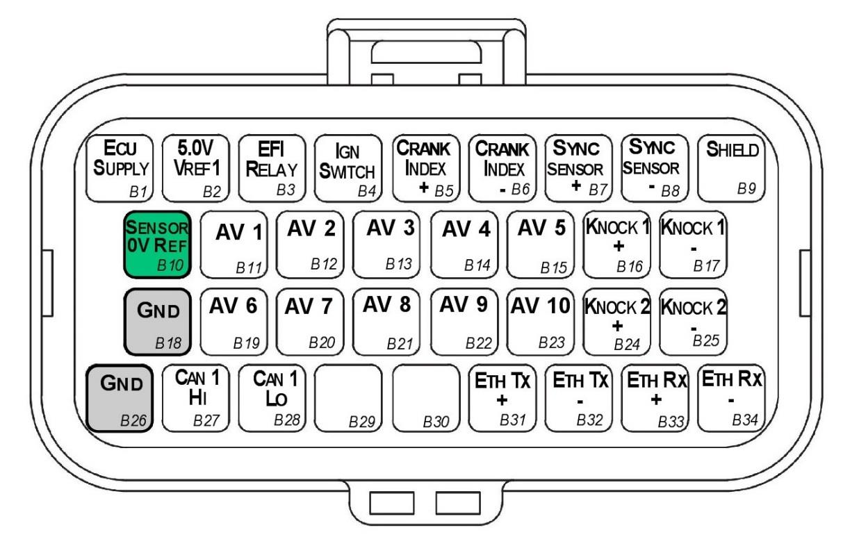
SL4 Connector B — looking into ECU connector.
| Pin | Channel Name | Pin | Channel Name |
|---|---|---|---|
| B1 | ECU 14V Supply | B18 | ECU Ground |
| B2 | Sensor Supply Vref1: 5.0V | B19 | Analog Input Channel 6 |
| B3 | EFI Relay Output (Low Side 200mA) | B20 | Analog Input Channel 7 |
| B4 | Ignition Switch Input | B21 | Analog Input Channel 8 |
| B5 | Crank Index Sensor + | B22 | Analog Input Channel 9 |
| B6 | Crank Index Sensor - | B23 | Analog Input Channel 10 |
| B7 | Sync Sensor + | B24 | Knock 2 + |
| B8 | Sync Sensor - | B25 | Knock 2 - |
| B9 | Shield (Crank/Sync/Knock) | B26 | ECU Ground |
| B10 | Analog Sensor 0V Reference | B27 | CAN 1H |
| B11 | Analog Input Channel 1 | B28 | CAN 1L |
| B12 | Analog Input Channel 2 | B29 | NC |
| B13 | Analog Input Channel 3 | B30 | NC |
| B14 | Analog Input Channel 4 | B31 | Ethernet Tx + |
| B15 | Analog Input Channel 5 | B32 | Ethernet Tx - |
| B16 | Knock 1 + | B33 | Ethernet Rx + |
| B17 | Knock 1 - | B34 | Ethernet Rx - |
6.1 Important Notes
Analog Sensor 0V Reference (Pin B10)
This pin should be connected directly to the 0V (Ground) pin on any low current analog sensor, for example Pressure or Temperature.
- DO NOT connect the ECU pin B10 directly to the Engine Block or ECU Ground. These are dedicated and specialised ground outputs for all analog channels and should be connected directly to the sensor.
- DO NOT connect frequency-based sensors to these pins; for example, an Ethanol content sensor. The sensor 0V pin should be connected to the ECU ground.
Half Bridge Driver Power Supply Input (Pin A34)
Pin A34 is a dedicated power supply for Auxiliary Channels 9-10. Power must be supplied to this pin for these channels to operate correctly. In non-DBW (Drive by Wire) applications the ECU Supply power can be shared, assuming the wire gauge has a sufficient rating for the current demand. In DBW applications power to this pin MUST come from an ECU controlled DBW Relay.
7.0 Software
Emtron’s comprehensive Emtune tuning software is used to connect to the ECU.
- Microsoft Windows™ 7-10 compatible
- Free licence
- Memory requirements: 0.5GB RAM
- ECU connection using Ethernet, IPV4 protocol
- Tuning and data analysis
- PC and ECU data logging
- Live pause and data playback
- Advanced tuning functions
- Diagnostics
- Oscilloscope display
8.0 Ordering Information
| Product | Part Number |
|---|---|
| Emtron SL4 ECU | 1912-042 |
| Emtron Ethernet Tuning Cable (1.5m) | 553-15 |
| Emtron Communications Cable, Superseal to Emtron Connector 200mm | 533-02 |
Appendix A – SL4 ECU Pinout Drawing
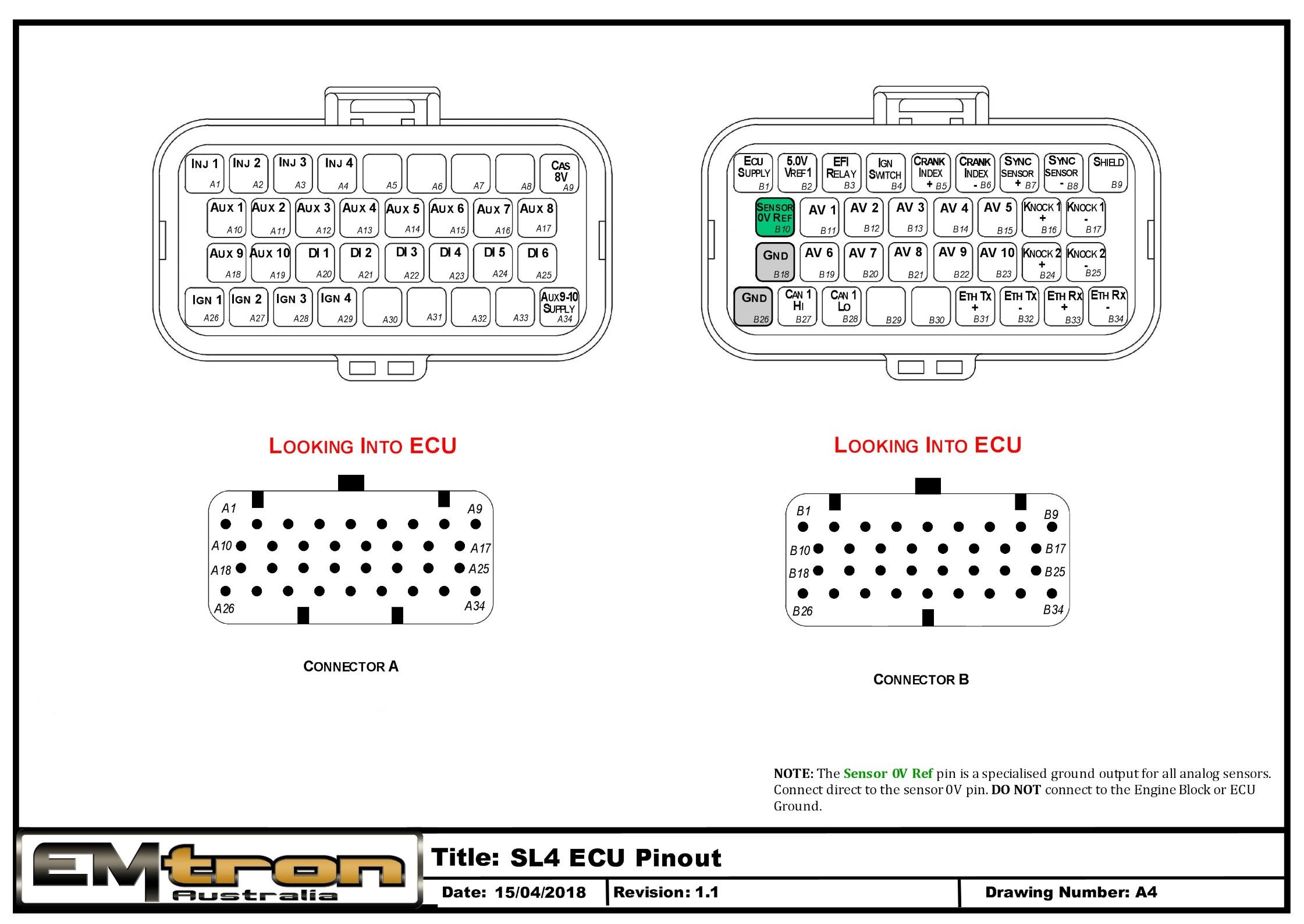
SL4 ECU pinout — Connector A and Connector B, looking into ECU. The Sensor 0V Ref pin is a specialised ground output for all analog sensors; connect direct to the sensor 0V pin.
Appendix B – SL Series ECU Wiring
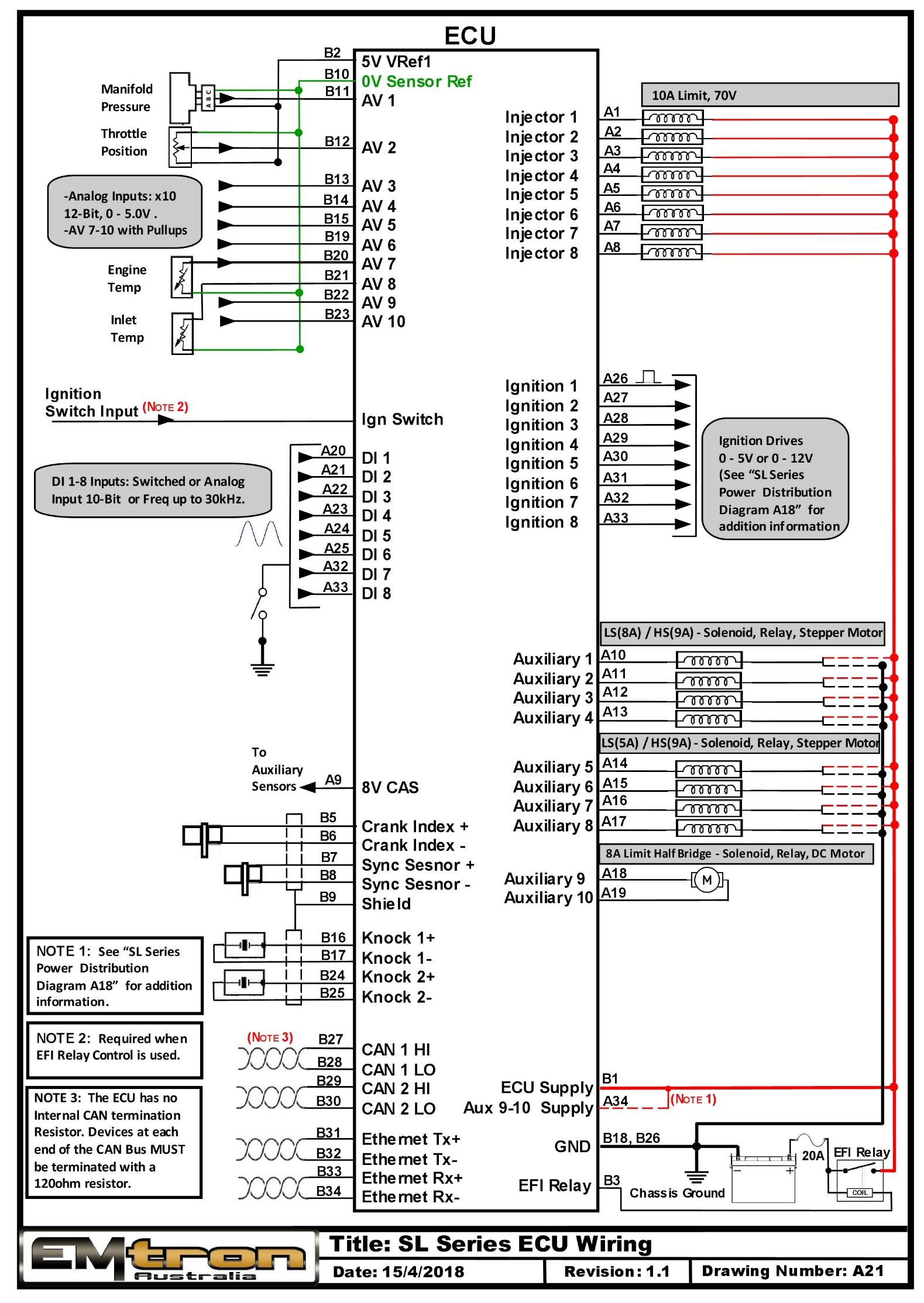
SL Series ECU typical wiring (drawing A21).
Appendix C – SL Series Ethernet Wiring
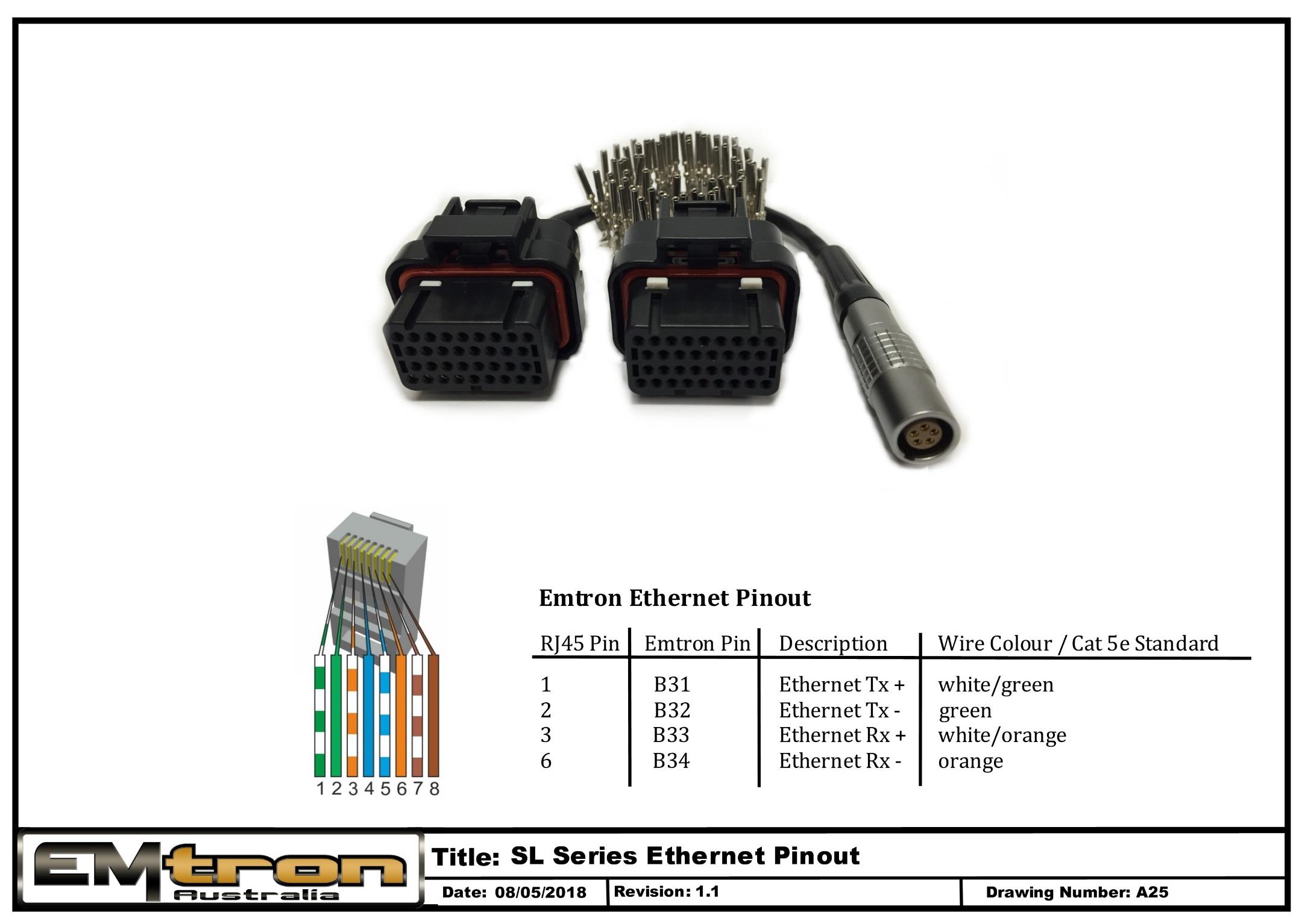
SL Series Ethernet pinout / tuning cable wiring (drawing A25).
SL6 ECU Datasheet
Emtron SL6 ECU
1.0 General
Emtron’s SL Series is built upon the outstanding foundation of the KV Series and features the same processing power and logging capacity. This lightweight package is housed in a Billet Aluminium Enclosure and features a 68-pin connector system which is still a very high I/O count. The SL6 ECU will support up to 8 Channels of fully sequential Fuel and Ignition. Up to 32MB permanent memory for on-board logging is available, 4-channel oscilloscope function, DBW control, Knock control up to 2 channels using digital filter technology, High Speed Ethernet communications and 3-axis G-force sensing to name a few.
Power Supply
- Operating voltage: 6.0 to 22.0 Volts DC (ECU shutdowns at 24.0V)
- Operating current: 290mA at 14.0V (excluding sensor and load currents)
- Reverse battery protection via external fuse
- “Smart” battery transient protection
Operating Temperature
- Max operating range: -30 to 110°C (-22 to 230°F)
- Recommended operating range: -30 to 85°C (-22 to 185°F)
Physical
- Aluminium 6061 grade CNC billet enclosure
- Enclosure size 120 mm x 130 mm x 27 mm
- Weight: 470g
- Connector system: 68-way Super Seal waterproof connectors with gold plated contacts
- Pin diameter: 1 mm
- Current rating: maximum 15A per pin (wire gauge dependant)
- Connector A: 34 pin Key 2 Super Seal
- Connector B: 34 pin Key 1 Super Seal
Internal
- Dual 100MHz processors
- 500Mb DDR RAM (0.5Gb)
- 32MB ECU logging memory
- Over 1200 channels available
- 1Hz to 500Hz logging rate
- Oscilloscope 4-channel function with 32MB storage
- Sampling at 100k samples/second
- Includes Crank Index and Sync sensor inputs
- Includes Digital Inputs 1-4
- On-Board barometric pressure sensor
- Range 40 - 115.0 kPa
- 3-Axis accelerometer
- 16-Bit resolution
- +2g/+4g/+8g dynamically selectable full-scale
- Output data rate 500Hz
2.0 Outputs
6x Port Injector Outputs — high ohm
- 70V clamping
- Outputs can be used for ground switching, 6A Continuous, 10A Limit
- All outputs are short circuit and over current protected
- No Flywheel diodes (external diode(s) required for VVT control)
6x Ignition Outputs
- Adjustable TTL Ignition drive current (35mA or 70mA)
- Outputs can be used for ground switching, 1A Continuous, 3A Limit
- All outputs are short circuit and over current protected
- No Flywheel diodes (external diode(s) required for VVT control)
10x Auxiliary Outputs
- Variable Valve Timing (VVT) and Variable Valve Timing Electric (VTiE), Drive by Wire (DBW), dual boost control, gearshift solenoids, stepper motor and many more.
- All outputs have PWM control, maximum frequency = 15 kHz
- Flywheel diodes integrated into all outputs
- Auxiliary 1-8 Flywheel to the “ECU Supply” pin B1 connector B
- Auxiliary 9-10 Flywheel to the “ECU 9-12 Supply” pin A34 connector A
- All outputs are short circuit and over current protected
Low Side Drivers
- Auxiliary 1-4: Low Side 4A continuous, 6A peak modulated, 8A limit
- Auxiliary 5-8: Low Side 2.5A continuous, 4A peak modulated, 5A limit
High Side Drivers
- Auxiliary 1-8: High Side 4A continuous, 9A limit
Half Bridge Drivers
- Auxiliary 9-10: Half Bridge 5A continuous and 8A limit. Can be used as Low Side, High Side or together in H-bridge configuration for DC motor control (DBW)
1x EFI Relay Output
- Low Side Driver for relay control. Current limited to 200mA (Output will switch ON when Ignition Switch Input (B4) is greater than 4V)
1x Shield Output
- Connection for Trigger and Knock shielded cables. Short to battery protection
3.0 Inputs
10x Analog Voltage/Temperature Inputs
- Fully configurable including custom calibrations
- Switchable 1k ohm pull-up resistors on ANV 7-10
- Accepts a 0.0 - 5.000V analog input. Resolution is 1.22mV (12-Bit)
- Input Impedance 100k Ohms to ground
6x Digital/Speed Inputs/Switched Inputs
- Frequency range from 0.0Hz up to 30.0kHz on all 6 channels
- Magnetic and Hall effect sensor compatible on DI 1-4 with programmable trigger edge(s)
- Hall effect sensor only on DI 5-6 with programmable trigger edge(s)
- Independent programmable frequency-based arming threshold control, range 0.0 - 12.0V on DI 1-4
- Fixed frequency-based arming thresholds on DI 5-6. Rising = 1.2V, Falling = 1.0V.
- Wheel speed, output shaft speed and other frequency-based signals
- VVT position(s) up to 4 channels available on DI 1-4.
- ON/OFF switched inputs: AC request, Launch enable, cruise switch, table control switching etc with arming threshold control, range 0.0 - 20.0V
- Accepts a 0.0 - 20.0V analog input. Resolution is 4.88mV (10-Bit)
- Switchable 4k7 ohm pull-up resistors on all 6 channels to 10V
- Maximum input signal amplitude +/- 80V
2x Knock Inputs
- 2 Independent knock input channels
- Using Bosch, Digital Knock Integrated Circuit Technology with programmable digital filter coefficients
- Center frequency configurable from 500Hz - 25kHz
- Bandwidth window from 100Hz - 5kHz
- Digital filter window; Hamming or Blackman
- Gain control (x1, x2, x4, x8)
- Cylinder selectable knock input
- Knock control available on ALL Ignition modes (Direct, Wasted, Distributor etc)
1x Dedicated Ignition Switch Input
- 6.0 - 20.0V input used for EFI Relay Control. (With input > 4V the EFI Relay output (D9) will switch ON)
2x Crank Index and Sync Engine Decoding Inputs
- Magnetic and Hall effect sensor compatible with programmable trigger edge(s)
- “True” zero crossing detection on magnetic signals for precise engine position decoding.
- Programmable independent arming threshold control from 0.1V to 12.0V
- Switchable 4k7 ohm pull-up resistor to 5V
- OEM patterns supported
- Maximum input signal amplitude +/- 80V
- Input Impedance 39k ohms to ground
4.0 Voltage and Ground Supplies
1x ECU Supply Input
- 15.0A Max (pin limited)
- 6V - 22.0V Range
- Supplies ECU power
- Supplies power to Auxiliary 1-8 High Side Drivers
1x Auxiliary 9-10 Supply Input
- 15.0A Max (pin limited)
- Power supply for Auxiliary channels 9-10. (See the SL Series Power Distribution Wiring for more information on how this should be wired. Also see Section 6.1)
1x 5.0V Sensor Supply
- 5V Vref1 output current 250mA
1x 8.0V Sensor Supply
- Output current 400mA
2x ECU Main Grounds
- 15.0A per pin, total 30A
1x Sensor 0V Reference
- Analog Sensor 0V Reference with short to battery protection (See note in Section 6.1)
NoteNOTE The Sensor 0V Reference pin(s) are specialised ground outputs for all analog sensors. Connect direct to the sensor 0V pin, DO NOT connect to the Engine Block or ECU Ground.
5.0 Communications
- 1x High Speed Ethernet 100Mbps for tuning software connection
- 2x CAN 2.0B 1Mbps / 6 Channels per node, total 128 messages
6.0 SL6 Pinout
Connector A: Injection / Ignition / Auxiliary Outputs
(15.0A Max continuous current - wire gauge dependant)
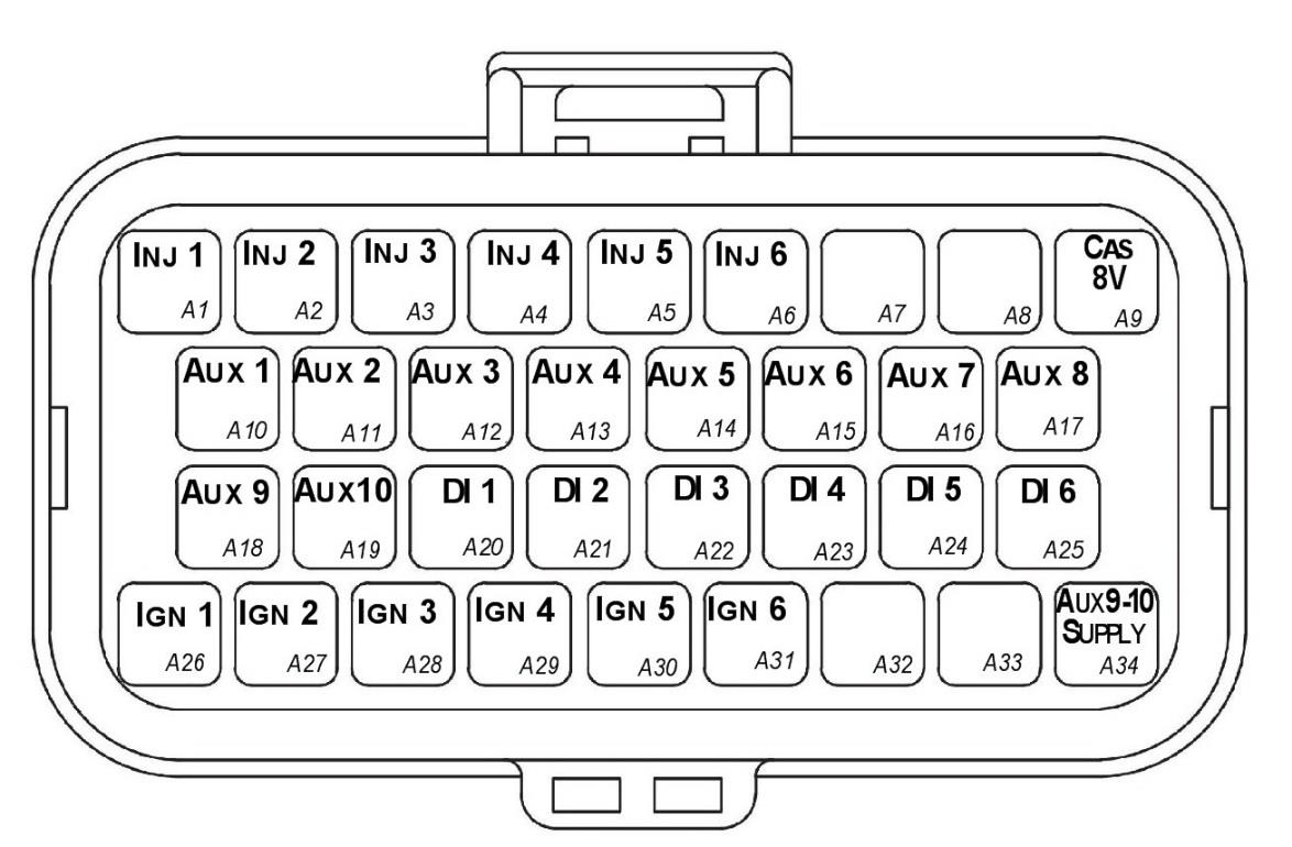
SL6 Connector A — looking into ECU connector.
| Pin | Channel Name | Pin | Channel Name |
|---|---|---|---|
| A1 | Injection Channel 1 | A18 | Auxiliary Output 9 |
| A2 | Injection Channel 2 | A19 | Auxiliary Output 10 |
| A3 | Injection Channel 3 | A20 | Digital Input 1 |
| A4 | Injection Channel 4 | A21 | Digital Input 2 |
| A5 | Injection Channel 5 | A22 | Digital Input 3 |
| A6 | Injection Channel 6 | A23 | Digital Input 4 |
| A7 | NC | A24 | Digital Input 5 |
| A8 | NC | A25 | Digital Input 6 |
| A9 | Sensor Supply 8V | A26 | Ignition Channel 1 |
| A10 | Auxiliary Output 1 | A27 | Ignition Channel 2 |
| A11 | Auxiliary Output 2 | A28 | Ignition Channel 3 |
| A12 | Auxiliary Output 3 | A29 | Ignition Channel 4 |
| A13 | Auxiliary Output 4 | A30 | Ignition Channel 5 |
| A14 | Auxiliary Output 5 | A31 | Ignition Channel 6 |
| A15 | Auxiliary Output 6 | A32 | NC |
| A16 | Auxiliary Output 7 | A33 | NC |
| A17 | Auxiliary Output 8 | A34 | Auxiliary Output 9-10, 14V Supply |
NC = No Connect
Connector B: Signal / Power / Communications / Triggers / Knock
(15.0A Max continuous current - wire gauge dependant)
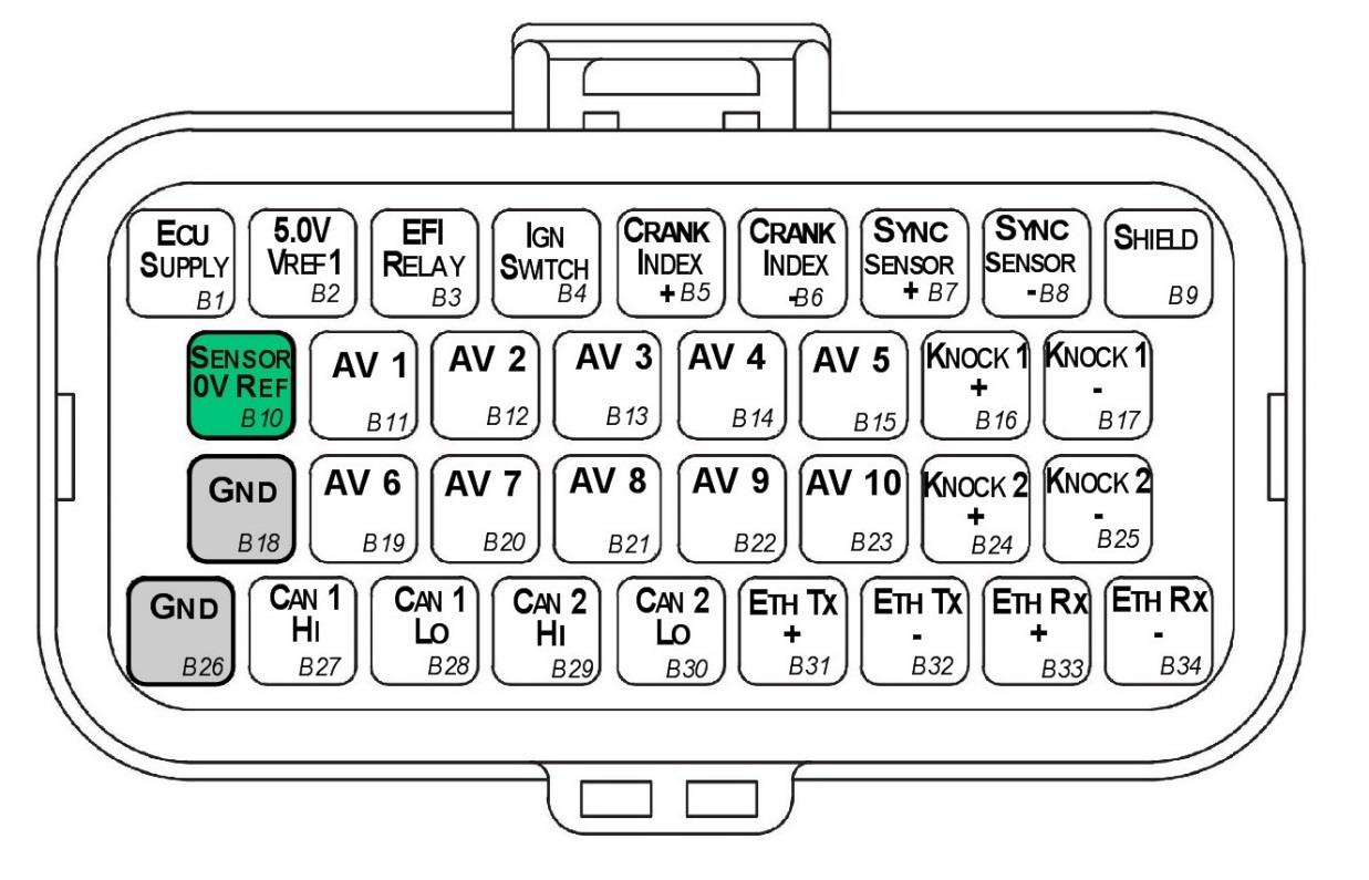
SL6 Connector B — looking into ECU connector.
| Pin | Channel Name | Pin | Channel Name |
|---|---|---|---|
| B1 | ECU 14V Supply | B18 | ECU Ground |
| B2 | Sensor Supply Vref1: 5.0V | B19 | Analog Input Channel 6 |
| B3 | EFI Relay Output (Low Side 200mA) | B20 | Analog Input Channel 7 |
| B4 | Ignition Switch Input | B21 | Analog Input Channel 8 |
| B5 | Crank Index Sensor + | B22 | Analog Input Channel 9 |
| B6 | Crank Index Sensor - | B23 | Analog Input Channel 10 |
| B7 | Sync Sensor + | B24 | Knock 2 + |
| B8 | Sync Sensor - | B25 | Knock 2 - |
| B9 | Shield (Crank/Sync/Knock) | B26 | ECU Ground |
| B10 | Analog Sensor 0V Reference | B27 | CAN 1H |
| B11 | Analog Input Channel 1 | B28 | CAN 1L |
| B12 | Analog Input Channel 2 | B29 | CAN 2H |
| B13 | Analog Input Channel 3 | B30 | CAN 2L |
| B14 | Analog Input Channel 4 | B31 | Ethernet Tx + |
| B15 | Analog Input Channel 5 | B32 | Ethernet Tx - |
| B16 | Knock 1 + | B33 | Ethernet Rx + |
| B17 | Knock 1 - | B34 | Ethernet Rx - |
6.1 Important Notes
Analog Sensor 0V Reference (Pin B10)
This pin should be connected directly to the 0V (Ground) pin on any low current analog sensor, for example Pressure or Temperature.
- DO NOT connect the ECU pin B10 directly to the Engine Block or ECU Ground. These are dedicated and specialised ground outputs for all analog channels and should be connected directly to the sensor.
- DO NOT connect frequency-based sensors to these pins; for example, an Ethanol content sensor. The sensor 0V pin should be connected to the ECU ground.
Half Bridge Driver Power Supply Input (Pin A34)
Pin A34 is a dedicated power supply for Auxiliary Channels 9-10. Power must be supplied to this pin for these channels to operate correctly. In non-DBW (Drive by Wire) applications the ECU Supply power can be shared, assuming the wire gauge has a sufficient rating for the current demand. In DBW applications power to this pin MUST come from an ECU controlled DBW Relay.
7.0 Software
Emtron’s comprehensive Emtune tuning software is used to connect to the ECU.
- Microsoft Windows™ 7-10 compatible
- Free licence
- Memory requirements: 0.5GB RAM
- ECU connection using Ethernet, IPV4 protocol
- Tuning and data analysis
- PC and ECU data logging
- Live pause and data playback
- Advanced tuning functions
- Diagnostics
- Oscilloscope display
8.0 Ordering Information
| Product | Part Number |
|---|---|
| Emtron SL6 ECU | 1912-062 |
| Emtron Ethernet Tuning Cable (1.5m) | 553-15 |
| Emtron Communications Cable, Superseal to Emtron Connector 200mm | 533-02 |
Appendix A – SL6 ECU Pinout Drawing
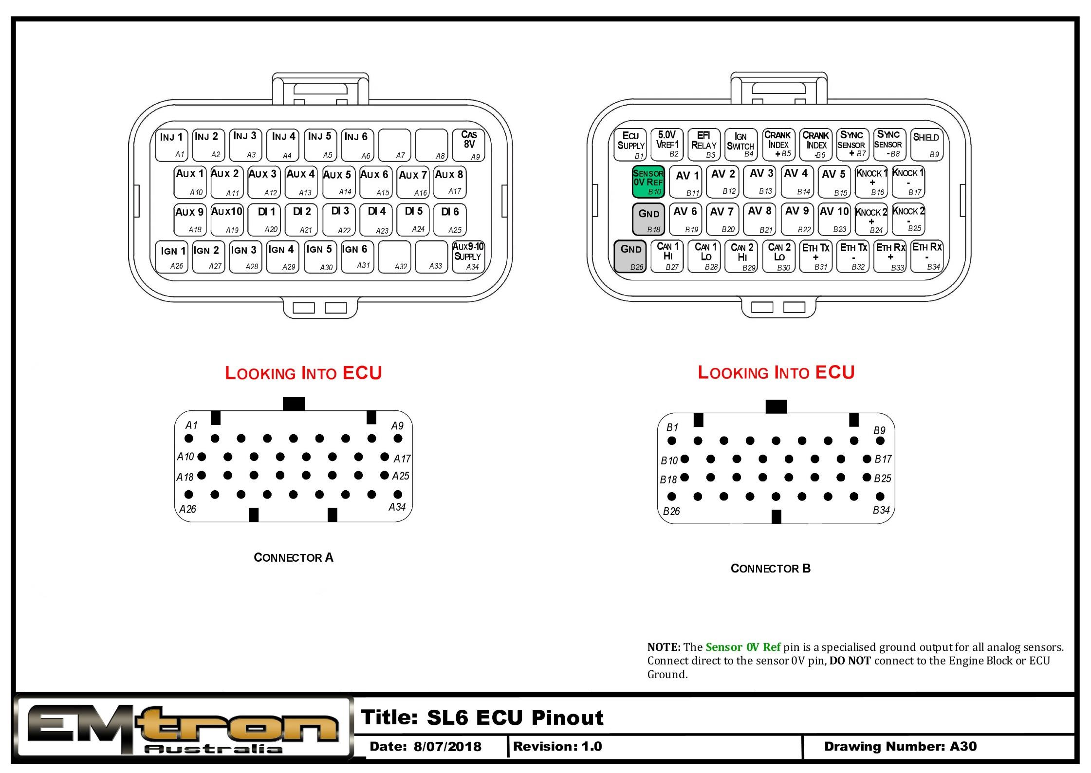
SL6 ECU pinout — Connector A and Connector B, looking into ECU. The Sensor 0V Ref pin is a specialised ground output for all analog sensors; connect direct to the sensor 0V pin.
Appendix B – SL Series ECU Wiring
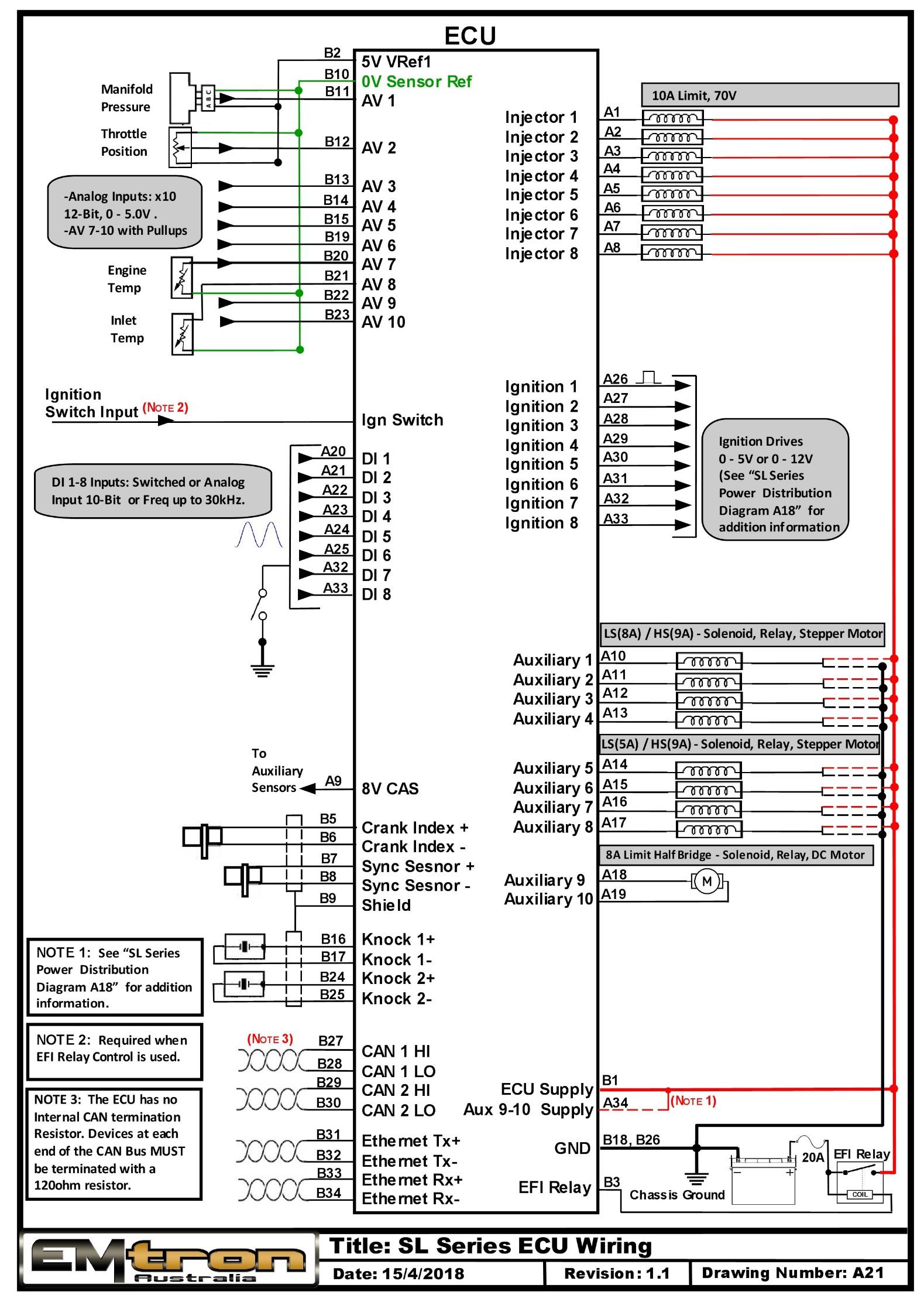
SL Series ECU typical wiring (drawing A21).
Appendix C – SL Series Ethernet Wiring
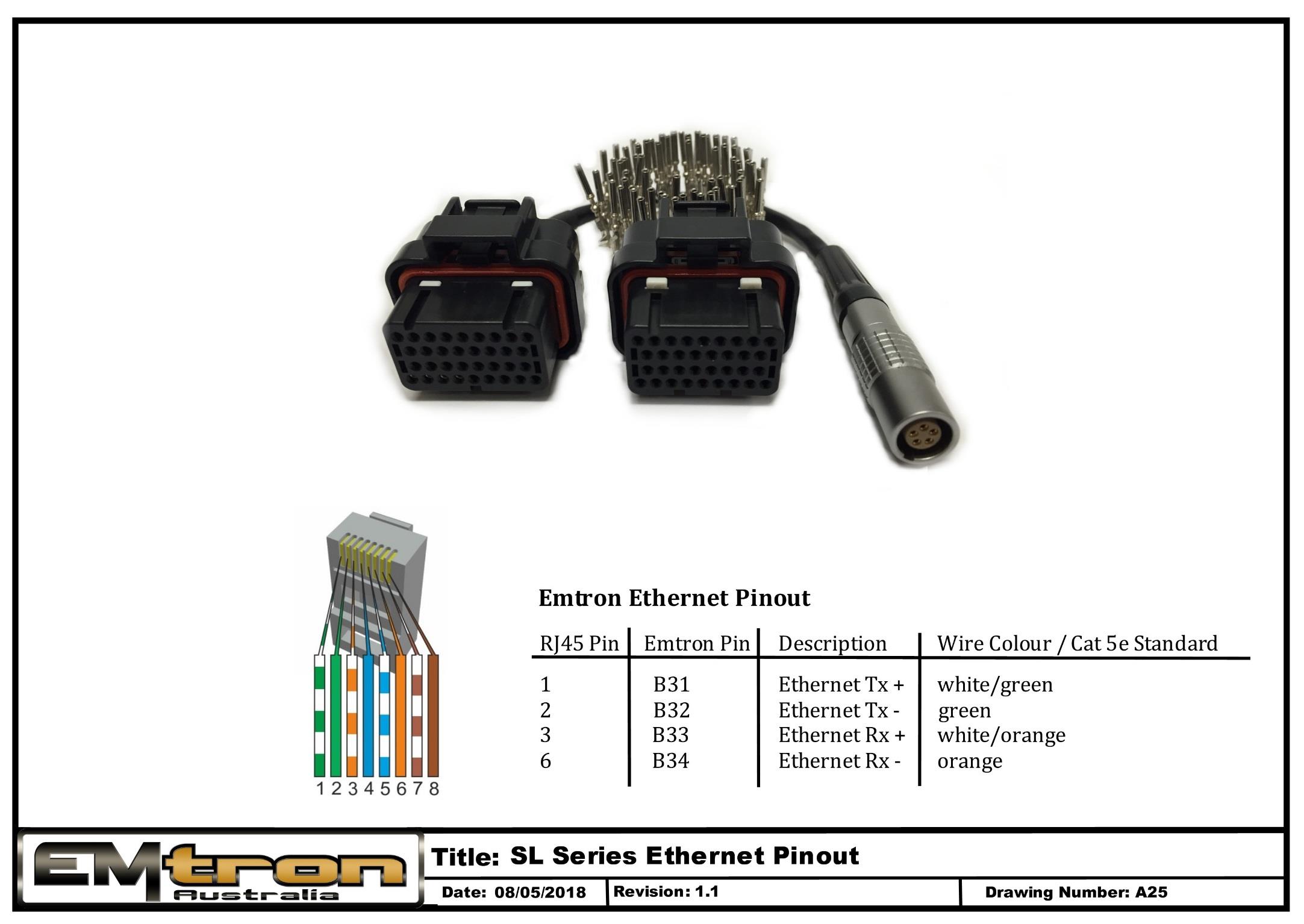
SL Series Ethernet pinout / tuning cable wiring (drawing A25).
SL8 ECU Datasheet
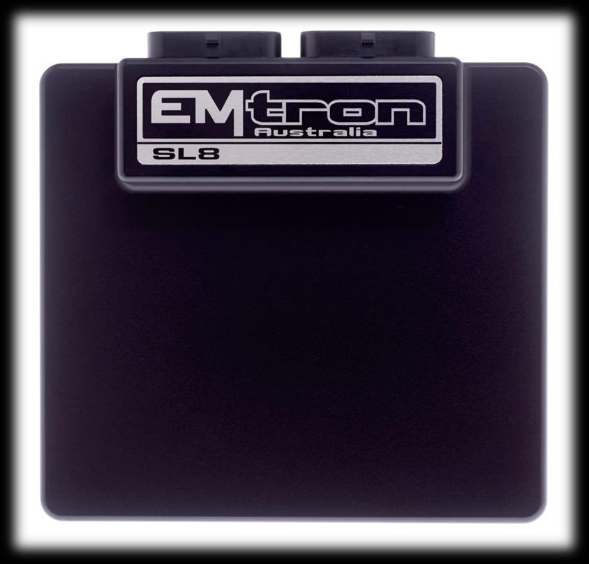
Emtron SL8 ECU
1.0 General
Emtron’s SL Series is built upon the outstanding foundation of the KV Series and features the same processing power and logging capacity. This lightweight package is housed in a Billet Aluminium Enclosure and features a 68-pin connector system which is still a very high I/O count. The SL8 ECU will support up to 8 Channels of fully sequential Fuel and Ignition. Up to 32MB permanent memory for on-board logging is available, 4-channel oscilloscope function, DBW control, Knock control up to 2 channels using digital filter technology, High Speed Ethernet communications and 3-axis G-force sensing to name a few.
Power Supply
- Operating voltage: 6.0 to 22.0 Volts DC (ECU shutdowns at 24.0V)
- Operating current: 290mA at 14.0V (excluding sensor and load currents)
- Reverse battery protection via external fuse
- “Smart” battery transient protection
Operating Temperature
- Max operating range: -30 to 110°C (-22 to 230°F)
- Recommended operating range: -30 to 85°C (-22 to 185°F)
Physical
- Aluminium 6061 grade CNC billet enclosure
- Enclosure size 120 mm x 130 mm x 27 mm
- Weight: 470g
- Connector system: 68-way Super Seal waterproof connectors with gold plated contacts
- Pin diameter: 1 mm
- Current rating: maximum 15A per pin (wire gauge dependant)
- Connector A: 34 pin Key 2 Super Seal
- Connector B: 34 pin Key 1 Super Seal
Internal
- Dual 100MHz processors
- 500Mb DDR RAM (0.5Gb)
- 32MB ECU logging memory
- Over 1200 channels available
- 1Hz to 500Hz logging rate
- Oscilloscope 4-channel function with 32MB storage
- Sampling at 100k samples/second
- Includes Crank Index and Sync sensor inputs
- Includes Digital Inputs 1-4
- On-Board barometric pressure sensor
- Range 40 - 115.0 kPa
- 3-Axis accelerometer
- 16-Bit resolution
- +2g/+4g/+8g dynamically selectable full-scale
- Output data rate 500Hz
2.0 Outputs
8x Port Injector Outputs — high ohm
- 70V clamping
- Outputs can be used for ground switching, 6A Continuous, 10A Limit
- All outputs are short circuit and over current protected
- No Flywheel diodes (external diode(s) required for VVT control)
8x Ignition Outputs
- Adjustable TTL Ignition drive current (35mA or 70mA)
- Outputs can be used for ground switching, 1A Continuous, 3A Limit
- All outputs are short circuit and over current protected
- No Flywheel diodes (external diode(s) required for VVT control)
10x Auxiliary Outputs
- Variable Valve Timing (VVT) and Variable Valve Timing Electric (VTiE), Drive by Wire (DBW), dual boost control, gearshift solenoids, stepper motor and many more.
- All outputs have PWM control, maximum frequency = 15 kHz
- Flywheel diodes integrated into all outputs
- Auxiliary 1-8 Flywheel to the “ECU Supply” pin B1 connector B
- Auxiliary 9-10 Flywheel to the “ECU 9-12 Supply” pin A34 connector A
- All outputs are short circuit and over current protected
Low Side Drivers
- Auxiliary 1-4: Low Side 4A continuous, 6A peak modulated, 8A limit
- Auxiliary 5-8: Low Side 2.5A continuous, 4A peak modulated, 5A limit
High Side Drivers
- Auxiliary 1-8: High Side 4A continuous, 9A limit
Half Bridge Drivers
- Auxiliary 9-10: Half Bridge 5A continuous and 8A limit. Can be used as Low Side, High Side or together in H-bridge configuration for DC motor control (DBW)
1x EFI Relay Output
- Low Side Driver for relay control. Current limited to 200mA (Output will switch ON when Ignition Switch Input (B4) is greater than 4V)
1x Shield Output
- Connection for Trigger and Knock shielded cables. Short to battery protection
3.0 Inputs
10x Analog Voltage/Temperature Inputs
- Fully configurable including custom calibrations
- Switchable 1k ohm pull-up resistors on ANV 7-10
- Accepts a 0.000 - 5.000V analog input. Resolution is 1.22mV (12-Bit)
- Input Impedance 100k Ohms to ground
8x Digital/Speed Inputs/Switched Inputs
- Frequency range from 0.0Hz up to 30.0kHz on all 8 channels
- Magnetic and Hall effect sensor compatible on DI 1-4 with programmable trigger edge(s)
- Hall effect sensor only on DI 5-8 with programmable trigger edge(s)
- Independent programmable frequency-based arming threshold control, range 0.0 - 12.0V on DI 1-4
- Fixed frequency-based arming thresholds on DI 5-8. Rising = 1.2V, Falling = 1.0V.
- Wheel speed, output shaft speed and other frequency-based signals
- VVT position(s) up to 4 channels available on DI 1-4.
- ON/OFF switched inputs: AC request, Launch enable, cruise switch, table control switching etc with arming threshold control, range 0.0 - 20.0V
- Accepts a 0.0 - 20.0V analog input. Resolution is 4.88mV (10-Bit)
- Switchable 4k7 ohm pull-up resistors on all 8 channels to 10V
- Maximum input signal amplitude +/- 80V
2x Knock Inputs with configurable Frequency and Gain
- Using Bosch digital knock integrated circuit technology
- Selectable center frequency from 500Hz - 25kHz
- Selectable bandwidth from 100Hz - 5kHz
- Selectable digital filter window; Hamming or Blackman
1x Dedicated Ignition Switch Input
- 6.0 - 20.0V input used for EFI Relay Control. (With input > 4V the EFI Relay output (D9) will switch ON)
2x Crank Index and Sync Engine Decoding Inputs
- Magnetic and Hall effect sensor compatible with programmable trigger edge(s)
- “True” zero crossing detection on magnetic signals for precise engine position decoding.
- Programmable independent arming threshold control from 0.1V to 12.0V
- Switchable 4k7 ohm pull-up resistor to 5V
- OEM patterns supported
- Maximum input signal amplitude +/- 80V
- Input Impedance 39k ohms to ground
4.0 Voltage and Ground Supplies
1x ECU Supply Input
- 15.0A Max (pin limited)
- 6V - 22.0V Range
- Supplies ECU power
- Supplies power to Auxiliary 1-8 High Side Drivers
1x Auxiliary 9-10 Supply Input
- 15.0A Max (pin limited)
- Power supply for Auxiliary channels 9-10. (See the SL Series Power Distribution Wiring for more information on how this should be wired. Also see Section 6.1)
1x 5.0V Sensor Supply
- 5V Vref1 output current 250mA
1x 8.0V Sensor Supply
- Output current 400mA
2x ECU Main Grounds
- 15.0A per pin, total 30A
1x Sensor 0V Reference
- Analog Sensor 0V Reference with short to battery protection (See note in Section 6.1)
NoteNOTE The Sensor 0V Reference pin(s) are specialised ground outputs for all analog sensors. Connect direct to the sensor 0V pin, DO NOT connect to the Engine Block or ECU Ground.
5.0 Communications
- 1x high speed Ethernet 100Mbps
- 2x CAN 2.0B 1Mbps / 6 Channels per node, total 128 messages.
6.0 SL8 Pinout
Connector A: Injection / Ignition / Auxiliary Outputs
(15.0A Max continuous current - wire gauge dependant)
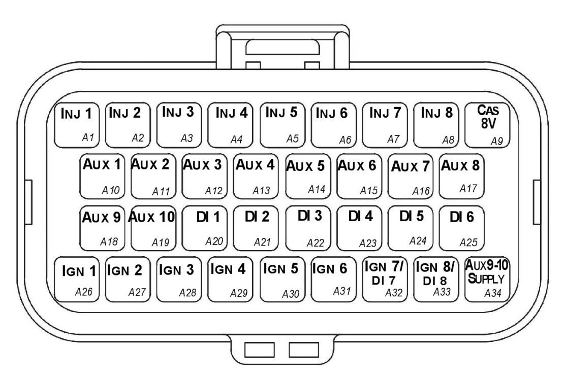
SL8 Connector A — looking into ECU connector.
| Pin | Channel Name | Pin | Channel Name |
|---|---|---|---|
| A1 | Injection Channel 1 | A18 | Auxiliary Output 9 |
| A2 | Injection Channel 2 | A19 | Auxiliary Output 10 |
| A3 | Injection Channel 3 | A20 | Digital Input 1 |
| A4 | Injection Channel 4 | A21 | Digital Input 2 |
| A5 | Injection Channel 5 | A22 | Digital Input 3 |
| A6 | Injection Channel 6 | A23 | Digital Input 4 |
| A7 | Injection Channel 7 | A24 | Digital Input 5 |
| A8 | Injection Channel 8 | A25 | Digital Input 6 |
| A9 | Sensor Supply 8V | A26 | Ignition Channel 1 |
| A10 | Auxiliary Output 1 | A27 | Ignition Channel 2 |
| A11 | Auxiliary Output 2 | A28 | Ignition Channel 3 |
| A12 | Auxiliary Output 3 | A29 | Ignition Channel 4 |
| A13 | Auxiliary Output 4 | A30 | Ignition Channel 5 |
| A14 | Auxiliary Output 5 | A31 | Ignition Channel 6 |
| A15 | Auxiliary Output 6 | A32 | Ignition Channel 7 / Digital Input 7 |
| A16 | Auxiliary Output 7 | A33 | Ignition Channel 8 / Digital Input 8 |
| A17 | Auxiliary Output 8 | A34 | Auxiliary Output 9-10, 14V Supply |
Connector B: Signal / Power / Communications / Triggers / Knock
(15.0A Max continuous current - wire gauge dependant)
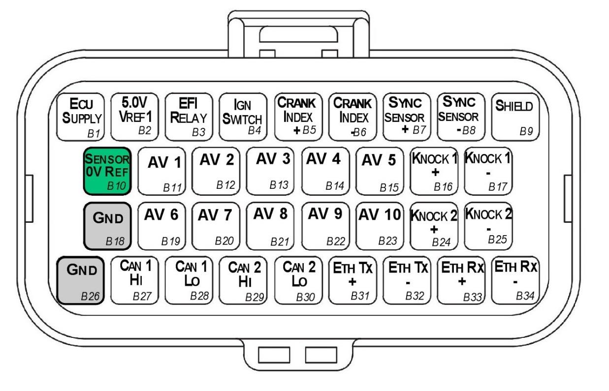
SL8 Connector B — looking into ECU connector.
| Pin | Channel Name | Pin | Channel Name |
|---|---|---|---|
| B1 | ECU 14V Supply | B18 | ECU Ground |
| B2 | Sensor Supply Vref1: 5.0V | B19 | Analog Input Channel 6 |
| B3 | EFI Relay Output (Low Side 200mA) | B20 | Analog Input Channel 7 |
| B4 | Ignition Switch Input | B21 | Analog Input Channel 8 |
| B5 | Crank Index Sensor + | B22 | Analog Input Channel 9 |
| B6 | Crank Index Sensor - | B23 | Analog Input Channel 10 |
| B7 | Sync Sensor + | B24 | Knock 2 + |
| B8 | Sync Sensor - | B25 | Knock 2 - |
| B9 | Shield (Crank/Sync/Knock) | B26 | ECU Ground |
| B10 | Analog Sensor 0V Reference | B27 | CAN 1H |
| B11 | Analog Input Channel 1 | B28 | CAN 1L |
| B12 | Analog Input Channel 2 | B29 | CAN 2H |
| B13 | Analog Input Channel 3 | B30 | CAN 2L |
| B14 | Analog Input Channel 4 | B31 | Ethernet Tx + |
| B15 | Analog Input Channel 5 | B32 | Ethernet Tx - |
| B16 | Knock 1 + | B33 | Ethernet Rx + |
| B17 | Knock 1 - | B34 | Ethernet Rx - |
6.1 Important Notes
Analog Sensor 0V Reference (Pin B10)
This pin should be connected directly to the 0V (Ground) pin on any low current analog sensor, for example Pressure or Temperature.
- DO NOT connect the ECU pin B10 directly to the Engine Block or ECU Ground. These are dedicated and specialised ground outputs for all analog channels and should be connected directly to the sensor.
- DO NOT connect frequency-based sensors to these pins; for example, an Ethanol content sensor. The sensor 0V pin should be connected to the ECU ground.
Half Bridge Driver Power Supply Input (Pin A34)
Pin A34 is a dedicated power supply for Auxiliary Channels 9-10. Power must be supplied to this pin for these channels to operate correctly. In non-DBW (Drive by Wire) applications the ECU Supply power can be shared, assuming the wire gauge has a sufficient rating for the current demand. In DBW applications power to this pin MUST come from an ECU controlled DBW Relay.
7.0 Software
Emtron’s comprehensive Emtune tuning software is used to connect to the ECU.
- Microsoft Windows™ 7-10 compatible
- Free licence
- Memory requirements: 0.5GB RAM
- ECU connection using Ethernet, IPV4 protocol
- Tuning and data analysis
- PC and ECU data logging
- Live pause and data playback
- Advanced tuning functions
- Diagnostics
- Oscilloscope display
8.0 Ordering Information
| Product | Part Number |
|---|---|
| Emtron SL8 ECU | 1912-082 |
| Emtron Ethernet Tuning Cable (1.5m) | 553-15 |
| Emtron Communications Cable, Superseal to Emtron Connector 200mm | 533-02 |
Appendix A – SL8 ECU Pinout Drawing
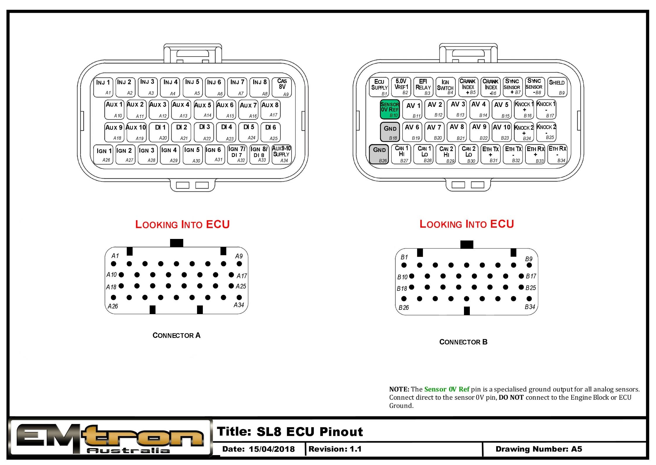
SL8 ECU pinout — Connector A and Connector B, looking into ECU. The Sensor 0V Ref pin is a specialised ground output for all analog sensors; connect direct to the sensor 0V pin.
Appendix B – SL Series ECU Wiring
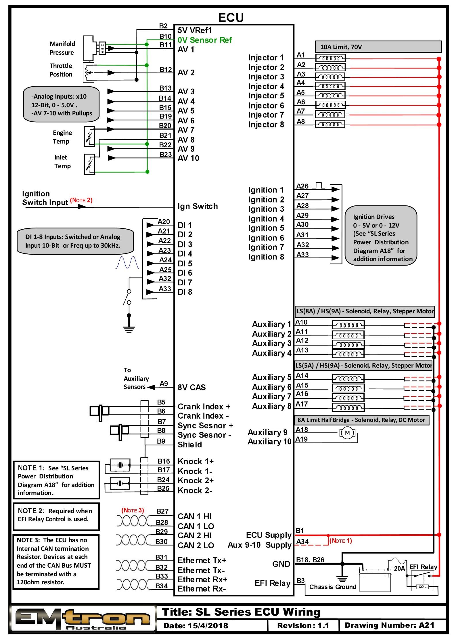
SL Series ECU typical wiring (drawing A21).
Appendix C – SL Series Ethernet Wiring
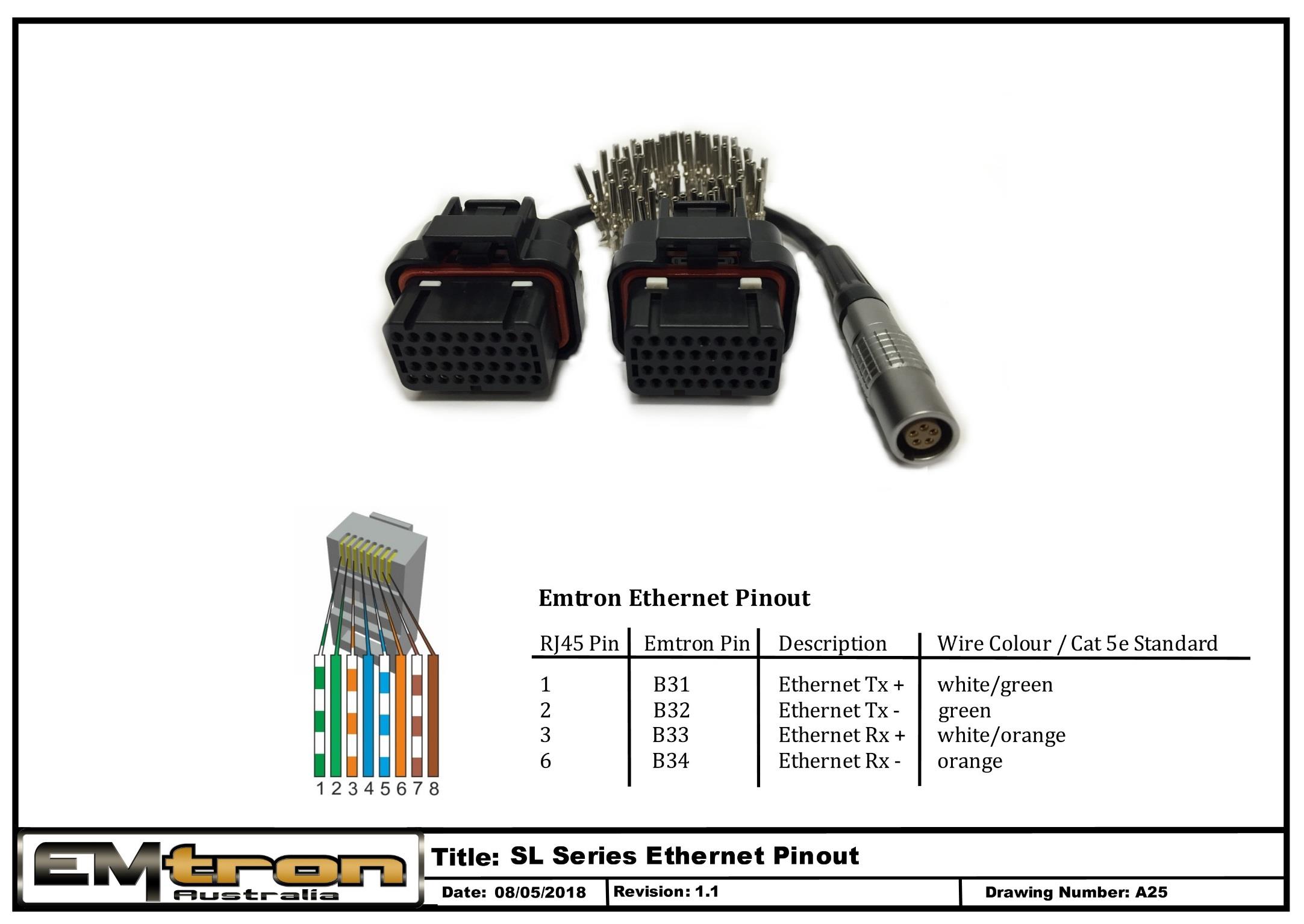
SL Series Ethernet pinout / tuning cable wiring (drawing A25).
Shadow 8 ECU Datasheet
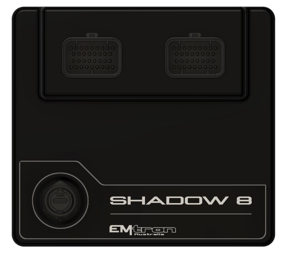
Emtron Shadow 8 ECU
1.0 General
The Shadow ECU range is built upon the outstanding foundation of the KV Series. This lightweight package is housed in a Billet Aluminium Enclosure and features a comprehensive 68-pin connector system. The Shadow ECU will support up to 8 Channels of fully sequential Fuel and Ignition. Up to 16MB permanent memory for on-board logging is available, DBW control, Knock control up to 2 channels using digital filter technology, and High-Speed USB C communications.
Functionality Count
- 8x Injection
- 8x Ignition
- 10x Analog Input
- 10x Digital Inputs
- 12x Auxiliary Outputs
- 2x CAN buses
- 2x Knock Inputs
- 2x GDI Pump Logic Control using Aux 11/12
- 1x DBW Control (Aux 9/10)
Power Supply
- Operating voltage: 6.0 to 22.0 Volts DC (ECU shutdowns at 24.0V)
- Operating current: 290mA at 14.0V (excluding sensor and load currents)
- Reverse battery protection via external fuse
- “Smart” battery transient protection
Operating Temperature
- Max operating range: -30 to 110°C (-22 to 230°F)
- Recommended operating range: -30 to 85°C (-22 to 185°F)
Physical
- Aluminium 6061 grade CNC billet enclosure
- Enclosure size 152 mm x 139 mm x 26 mm
- Weight: 520g
- Connector system: 68-way Super Seal waterproof connectors with gold plated contacts
- Pin diameter: 1 mm
- Current rating: maximum 15A per pin (wire gauge dependant)
- Connector A: 34 pin Key 1 Super Seal
- Connector B: 34 pin Key 2 Super Seal
Internal
- 100MHz Processor
- 16 MB ECU logging memory
- Over 1200 channels available
- 1Hz to 500Hz logging rate
2.0 Outputs
8x Port Injector Outputs — high ohm
- 70V clamping.
- Outputs can be used for ground switching, 6A Continuous, 10A Limit.
- All outputs are short circuit and over current protected.
- No Flywheel diodes (external diode(s) required for VVT control).
8x Ignition Outputs
- Adjustable TTL Ignition drive current (35mA or 70mA).
- Outputs can be used for ground switching, 1A Continuous, 3A Limit.
- All outputs are short circuit and over current protected.
- No Flywheel diodes (external diode(s) required for VVT control).
12x Auxiliary Outputs
- Variable Valve Timing (VVT) and Variable Valve Timing Electric (VTiE), Drive by Wire (DBW), dual boost control, gearshift solenoids, stepper motor and many more.
- All outputs have PWM control, maximum frequency = 10 kHz.
- Flywheel diodes integrated into all outputs.
- Auxiliary 1-8 Flywheel to the “Hot Supply” pin B1 connector B
- Auxiliary 9-12 Flywheel to the “Aux 9-12 Supply” pin B26 connector B
- All outputs are short circuit and over current protected.
Low Side Drivers
- Auxiliary 1-4: Low Side 4A continuous, 6A peak modulated, 8A limit.
- Auxiliary 5-8: Low Side 2.5A continuous, 4A peak modulated, 5A limit.
High Side Drivers
- Auxiliary 5-8: High Side 4A continuous, 8A limit.
Half Bridge Drivers
- Auxiliary 9-12: Half Bridge 5A continuous and 8A limit. Can be used as Low Side, High Side or together in H-bridge configuration for DC motor control (DBW).
1x Shield Output
- Connection for Trigger and Knock shielded cables. Short to battery protection.
3.0 Inputs
10x Analog Voltage/Temperature Inputs
- Fully configurable including custom calibrations.
- Switchable 1k ohm pull-up resistors on ANV 7-10.
- Accepts a 0.0 - 5.000V Analog input. Resolution is 1.22mV (12-Bit).
- Input Impedance 100k Ohms to ground.
10x Digital/Speed Inputs/Switched Inputs/Analog Inputs
- Frequency Range from 0.0Hz up to 5.0kHz on channels 1-4.
- Magnetic and Hall effect sensor compatible on DI 1-4, with programmable frequency-based arming threshold control, range 0.0 - 12.0V.
- Hall effect sensor only on DI 5-8 with fixed frequency-based arming thresholds (1.45V).
- Wheel speed, output shaft speed and other frequency-based signals.
- VVT position(s) up to 4 channels available on DI 1-4, Magnetic and Hall effect sensor compatible.
- DI1-10 all have ON/OFF switched control: AC request, Launch enable, Cruise switch, table control switching etc with arming threshold control, range 0.0 - 20.0V.
- DI1-10 channels ALL accept a 0.0 - 20.0V Analog input voltage. Resolution is 4.88mV (10-Bit).
- Switchable 4k7 ohm pull-up resistors on DI1-8 channels to 10V.
- Maximum input signal amplitude +/- 50V.
- Input Impedance 110k ohms to ground.
2x Knock Inputs
- 2 Independent knock input channels.
- Digital Knock Integrated Circuit Technology with programmable Centre Frequency, Gain and Integrator Time Constant.
- Centre frequency configurable from 1kHz - 20kHz.
- Gain control from 0.1 to 2.0.
- Cylinder selectable knock input.
- Knock control available on ALL Ignition modes (Direct, Wasted, Distributor etc).
2x Crank Index and Sync Engine Decoding Inputs
- Magnetic and Hall effect sensor compatible with programmable trigger edge(s)
- “True” zero crossing detection on magnetic signals for precise engine position decoding.
- Programmable independent arming threshold control from 0.1V to 12.0V
- Switchable 4k7 ohm pull-up resistor to 5V
- OEM patterns supported.
- Maximum input signal amplitude +/- 80V
- Input Impedance 100k ohms to ground.
1x Ignition Switch Input / DI10
- 6.0 - 20.0V input used for EFI Relay Control. (With input > 6V the Internal Hold-power system turns the ECU ON using the HOT Supply). Refer to the document “Shadow 8 Power Supply Wiring”.
4.0 Voltage and Ground Supplies
1x ECU Supply Input
- 15.0A Max (pin limited).
- 6V - 22.0V Range.
- Supplies ECU power.
- Supplies power to Auxiliary 1-8 High Side Drivers.
1x Auxiliary 9-12 Supply Input
- 15.0A Max (pin limited).
- Power supply for Auxiliary channels 9-12. (See “Shadow Series Power Distribution Wiring” for more information on how this should be wired. Refer Appendix B).
1x Battery Constant Supply Input
- 15.0A Max (pin limited).
- ECU MUST always have constant power. Used by Auxiliary Flywheel diodes and for the ECU automated shutdown procedure.
1x 5.0V Sensor Supply
- 5V Vref1 output current 250mA.
1x 8.0V Sensor Supply
- Output current 400mA.
2x ECU Main Grounds
- 15.0A per pin, total 30A.
1x Sensor 0V Reference
- Analog Sensor 0V Reference with short to battery protection (See note in Section 6.1).
NoteNOTE The Sensor 0V Reference pin(s) is a specialised ground output for all Analog sensors. Connect direct to the sensor 0V pin, DO NOT connect to the Engine Block or ECU Ground.
5.0 Communications
- 1x High Speed USB for tuning software connection.
- 2x CAN 2.0B 1Mbps / 6 Channels per node, total 128 messages.
6.0 Shadow 8 Pinout
Connector A: Signal / Power / Communications / Triggers / Knock
(15.0A Max continuous current - wire gauge dependant)
| Pin | Channel Name | Pin | Channel Name |
|---|---|---|---|
| A1 | ECU Supply | A18 | Analog Voltage 6 |
| A2 | Sensor 8.0V Sensor Supply | A19 | Analog Voltage 7 |
| A3 | Sensor 5.0V Sensor Supply | A20 | Analog Voltage 8 |
| A4 | 0V Analog Reference | A21 | Analog Voltage 9 |
| A5 | Crank Position Sensor | A22 | Analog Voltage 10 |
| A6 | Sync Position Sensor | A23 | CAN Bus 1 Low |
| A7 | Trigger Ground | A24 | Knock 2 +ve |
| A8 | Shield | A25 | Knock 2 -ve |
| A9 | Ground 1 | A26 | Digital Input 1 |
| A10 | Analog Voltage 1 | A27 | Digital Input 2 |
| A11 | Analog Voltage 2 | A28 | Digital Input 3 |
| A12 | Analog Voltage 3 | A29 | Digital Input 4 |
| A13 | Analog Voltage 4 | A30 | Digital Input 5 |
| A14 | Analog Voltage 5 | A31 | Digital Input 6 |
| A15 | CAN Bus 1 High | A32 | CAN Bus 2 High |
| A16 | Knock 1 +ve | A33 | CAN Bus 2 Low |
| A17 | Knock 1 -ve | A34 | Ground 2 |
Connector B: Injection / Ignition / Auxiliary Outputs
(15.0A Max continuous current - wire gauge dependant)
| Pin | Channel Name | Pin | Channel Name |
|---|---|---|---|
| B1 | Battery Constant (HOT) Supply | B18 | Digital Input 7 |
| B2 | Injector Cylinder 1 | B19 | Digital Input 8 |
| B3 | Injector Cylinder 2 | B20 | Digital Input 9 |
| B4 | Injector Cylinder 3 | B21 | Digital Input 10 / Ignition Switch |
| B5 | Injector Cylinder 4 | B22 | Aux Output 9 |
| B6 | Injector Cylinder 5 | B23 | Aux Output 10 |
| B7 | Injector Cylinder 6 | B24 | Aux Output 11 |
| B8 | Injector Cylinder 7 | B25 | Aux Output 12 |
| B9 | Injector Cylinder 8 | B26 | Aux 9-12 Power Supply |
| B10 | Aux Output 1 | B27 | Ignition TTL Cylinder 1 |
| B11 | Aux Output 2 | B28 | Ignition TTL Cylinder 2 |
| B12 | Aux Output 3 | B29 | Ignition TTL Cylinder 3 |
| B13 | Aux Output 4 | B30 | Ignition TTL Cylinder 4 |
| B14 | Aux Output 5 | B31 | Ignition TTL Cylinder 5 |
| B15 | Aux Output 6 | B32 | Ignition TTL Cylinder 6 |
| B16 | Aux Output 7 | B33 | Ignition TTL Cylinder 7 |
| B17 | Aux Output 8 | B34 | Ignition TTL Cylinder 8 |
Digital Inputs Summary
| Pin | Channel Name | Pullup Control | Type |
|---|---|---|---|
| A26 | Digital Input 1 (Wheel Speed) | Yes | Mag or Hall 0-5kHz, OR Analog 0-20V, Adj Arm |
| A27 | Digital Input 2 (Wheel Speed) | Yes | Mag or Hall 0-5kHz, OR Analog 0-20V, Adj Arm |
| A28 | Digital Input 3 (Wheel Speed) | Yes | Mag or Hall 0-5kHz, OR Analog 0-20V, Adj Arm |
| A29 | Digital Input 4 (Wheel Speed) | Yes | Mag or Hall 0-5kHz, OR Analog 0-20V, Adj Arm |
| A30 | Digital Input 5 | Yes | Hall 0-5kHz, Analog 0-20V, Fixed Arm 1.45V, SENT Protocol compatible |
| A31 | Digital Input 6 | Yes | Hall 0-5kHz, Analog 0-20V, Fixed Arm 1.45V, SENT Protocol compatible |
| B18 | Digital Input 7 | Yes | Hall 0-5kHz, Analog 0-20V, Fixed Arm 1.45V, SENT Protocol compatible |
| B19 | Digital Input 8 | Yes | Hall 0-5kHz, Analog 0-20V, Fixed Arm 1.45V, SENT Protocol compatible |
| B20 | Digital Input 9 | No Pullup | Analog 0-20V |
| B21 | Digital Input 10 / Ignition Switch | No Pullup | Analog 0-20V |
Auxiliary Output Summary
| Pin | Channel Name | Drive Type | Mode | Description |
|---|---|---|---|---|
| B10 | Aux Output 1 | LS Only Inductive or Resistive | ON/OFF or PWM | Relay or Solenoid |
| B11 | Aux Output 2 | LS Only Inductive or Resistive | ON/OFF or PWM | Relay or Solenoid |
| B12 | Aux Output 3 | LS Only Inductive or Resistive | ON/OFF or PWM | Relay or Solenoid |
| B13 | Aux Output 4 | LS Only Inductive or Resistive | ON/OFF or PWM | Relay or Solenoid |
| B14 | Aux Output 5 | LS or HS Inductive or Resistive | ON/OFF or PWM | Relay or Solenoid |
| B15 | Aux Output 6 | LS or HS Inductive or Resistive | ON/OFF or PWM | Relay or Solenoid |
| B16 | Aux Output 7 | LS or HS Inductive or Resistive | ON/OFF or PWM | Relay or Solenoid |
| B17 | Aux Output 8 | LS or HS Inductive or Resistive | ON/OFF or PWM | Relay or Solenoid |
| B22 | Aux Output 9 | Half Bridge DBW + | PWM | Engine Main Throttle |
| B23 | Aux Output 10 | Half Bridge DBW - | PWM | Engine Main Throttle |
| B24 | Aux Output 11 | Half Bridge | ON/OFF or PWM | Relay or Solenoid or GDI Pump Ctrl Signal |
| B25 | Aux Output 12 | Half Bridge | ON/OFF or PWM | Relay or Solenoid or GDI Pump Ctrl Signal |
Analog Input Pull-up Summary
| Pin | Channel Name | Pullup Control |
|---|---|---|
| A10 | Analog Input Channel 1 | No |
| A11 | Analog Input Channel 2 | No |
| A12 | Analog Input Channel 3 | No |
| A13 | Analog Input Channel 4 | No |
| A14 | Analog Input Channel 5 | No |
| A18 | Analog Input Channel 6 | No |
| A19 | Analog Input Channel 7 | Yes |
| A20 | Analog Input Channel 8 | Yes |
| A21 | Analog Input Channel 9 | Yes |
| A22 | Analog Input Channel 10 | Yes |
6.1 Important Notes
Analog Sensor 0V Reference (Pin A4)
This pin should be connected directly to the 0V (Ground) pin on any low current Analog sensor, for example Pressure or Temperature.
- DO NOT connect the ECU pin A4 directly to the Engine Block or ECU Ground. These are dedicated and specialised ground outputs for all Analog channels and should be connected directly to the sensor.
- DO NOT connect frequency-based sensors to these pins, for example, an Ethanol content sensor. Frequency based sensor 0V pins should be connected to the ECU ground.
Aux 9-12 (Half Bridge) Driver Power Supply Input (Pin B26)
Pin B26 is a dedicated power supply for Auxiliary Channels 9-12. Power must be supplied to this pin for these channels to operate correctly. In non-DBW (Drive by Wire) applications the ECU Supply power can be shared, assuming the wire gauge has a sufficient rating for the current demand. In DBW applications power to this pin MUST come from an ECU controlled DBW Relay.
Battery Constant Supply Input (Pin B1)
- Pin B1 should ALWAYS be connected to a constant 12V supply. (NOTE: The ECU draws zero current once completely shut down.)
- ALL Auxiliary flywheel control is directed to this pin.
- Constant power to this pin allows the ECU to control its power-down sequence. See “Shadow Series Power Distribution Wiring” for more information on how this should be wired and configured. Refer Appendix B.
Ignition TTL Outputs
WarningWARNING DO NOT connect these outputs directly to a coil. These Outputs are TTL or 0 – 7V which are designed to drive the input of an Ignitor. Connection directly to a coil will permanently damage the ECU!!
7.0 Software
Comprehensive Emtune tuning software is used to connect to the ECU.
- Microsoft Windows™ 7-11 compatible
- Free licence
- Memory requirements: 0.5GB RAM
- ECU connection using USB C
- Tuning and data analysis
- PC and ECU data logging
- Live pause and data playback
- Advanced tuning functions
- Diagnostics
8.0 Ordering Information
| Product | Part Number |
|---|---|
| Emtron Shadow ECU | 1908-082 |
| Emtron USB Tuning Cable (1.5m) |
Appendix A – Shadow 8 ECU Pinout Drawing
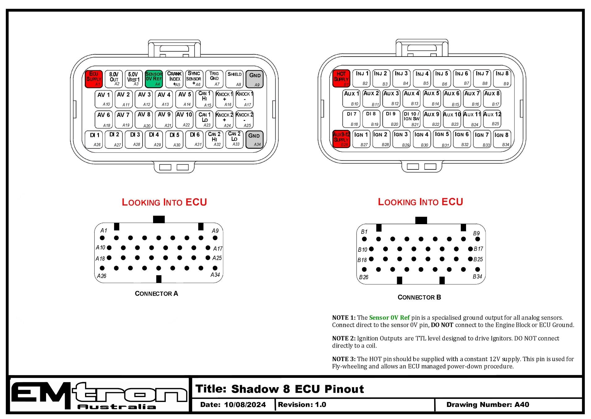
Shadow 8 ECU pinout — Connector A (signal/power) and Connector B (injection/ignition/aux), looking into ECU. Note the Sensor 0V Ref ground, the TTL ignition outputs, and the constant HOT supply requirement.
Appendix B – Shadow Series ECU Wiring
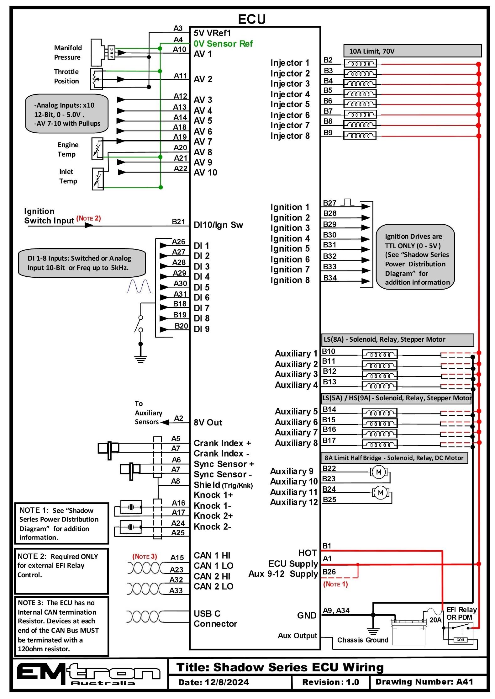
Shadow Series ECU typical wiring (drawing A41).
YXZ1000R Plugin ECU Datasheet
Emtron YXZ1000R Plugin ECU.
1.0 General
Emtron’s YXZ1000R Plugin ECU is built upon the outstanding foundation of the SL Series and features the same processing power and logging capacity. This lightweight package is housed in a Billet Aluminium Enclosure, designed to be plugged into the OEM harness to allow for a true “Plug and Play” install. As few inputs & outputs remain unused for User definition, CAN Bus 2 is made available providing additional I/O expandability. Other features include up to 32MB permanent memory for on-board logging, 4-channel oscilloscope function, DBW control, Knock control using digital filter technology, High Speed Ethernet communications and 3-axis G-force sensing.
Power Supply
- Operating voltage: 6.0 to 22.0 Volts DC (ECU shutdowns at 24.0V)
- Operating current: 290mA at 14.0V (excluding sensor and load currents)
- Reverse battery protection via external fuse
- “Smart” battery transient protection
Operating Temperature
- Max operating range: -30 to 110°C (-22 to 230°F)
- Recommended operating range: -30 to 85°C (-22 to 185°F)
Physical
- Aluminium 6061 grade CNC billet enclosure
- Enclosure size 120 × 130 × 27 mm
- Weight: 470g
- Connector system: 68-way Super Seal waterproof connectors with gold plated contacts (1mm pin, max 15A per pin). Connector A: 34 pin Key 2 Super Seal; Connector B: 34 pin Key 1 Super Seal.
Internal
- Dual 100MHz processors
- 500Mb DDR RAM (0.5Gb)
- 32MB ECU logging memory — over 1200 channels available, 1Hz to 500Hz logging rate
- Oscilloscope 4-channel function with 32MB storage (100k samples/second; includes Crank Index, Sync and Digital Inputs 1-4)
- On-Board barometric pressure sensor (40 - 115.0 kPa)
- 3-Axis accelerometer (16-Bit, +2g/+4g/+8g selectable, 500Hz output)
2.0 Outputs
8x Port Injector Outputs — high ohm
- 70V clamping; ground switching 6A Continuous, 10A Limit; short circuit & over current protected; no flywheel diodes (external diode(s) required for VVT control).
4x Ignition Outputs
- 3× Ignition outputs for direct-to-coil wiring (IGBT)
- 1× Adjustable TTL Ignition drive current (35mA or 70mA)
- Ground switching 1A Continuous, 3A Limit; short circuit & over current protected; no flywheel diodes.
10x Auxiliary Outputs
- Drive by Wire (DBW), dual boost control, gearshift solenoids, stepper motor and more. PWM control, max 15 kHz. Flywheel diodes integrated (Aux 1-8 to ECU Supply pin B1; Aux 9-10 to ECU 9-12 Supply pin A34). Short circuit & over current protected.
- Low Side: Aux 1-4 = 4A continuous / 6A peak / 8A limit; Aux 5-8 = 2.5A continuous / 4A peak / 5A limit.
- High Side: Aux 1-8 = 4A continuous, 9A limit.
- Half Bridge: Aux 9-10 = 5A continuous, 8A limit (Low Side, High Side or paired H-bridge for DBW).
3.0 Inputs
12x Analog Voltage/Temperature Inputs — Fully configurable with custom calibrations; switchable 1k ohm pull-ups on ANV 7-12; 0.0 - 5.000V, 1.22mV (12-Bit); 100k Ohms to ground.
14x Digital/Speed/Switched Inputs — 0.0Hz to 30.0kHz on channels 1-8; Magnetic + Hall on DI 1-4 (programmable trigger edge, adjustable arming 0.0-12.0V); Hall only on DI 5-8 (fixed arming Rising 1.2V / Falling 1.0V); ON/OFF switched inputs; 0.0-20.0V analog, 4.88mV (10-Bit); switchable 4k7 pull-ups on all 12 channels to 10V; max ±80V.
1x Knock Input — 1 independent channel; Bosch Digital Knock IC with programmable filter coefficients; centre frequency 500Hz - 25kHz; bandwidth 100Hz - 5kHz; Hamming or Blackman window; gain x1/x2/x4/x8; cylinder selectable; available on ALL ignition modes.
1x Crank Index Engine Decoding Input — OEM Magnetic sensor compatible; “True” zero crossing detection; programmable arming 0.1V to 12.0V; OEM pattern supported; max ±80V; 39k ohms to ground.
4.0 Voltage and Ground Supplies
- 2x ECU Supply Input — 15.0A Max (pin limited), 6V-22.0V, supplies ECU power and Auxiliary 1-10 High Side Drivers. (1× Dedicated battery power supply, 1× Ignition Power Supply.)
- 1x 5.0V Sensor Supply — 5V Vref1, 250mA.
- 4x ECU Main Grounds — 15.0A per pin, total 60A.
- 1x Sensor 0V Reference — Analog Sensor 0V Reference with short to battery protection.
NoteNOTE The Sensor 0V Reference pin(s) are specialised ground outputs for all analog sensors. Connect direct to the sensor 0V pin, DO NOT connect to the Engine Block or ECU Ground.
5.0 ECU Channel Assignment
Injection
| ECU Channel | Function |
|---|---|
| Injection 1-3 | Primary Injector Cylinder 1-3 |
| Injection 4 | Fuel Pump 1 (+Main relay) |
| Injection 5 | Cooling Fan 1 |
| Injection 6 | User Output 3 - Park Belt Buzzer |
| Injection 7 | Start Relay Control |
| Injection 8 | User Output 2 - Air Induction Relay |
Ignition
| ECU Channel | Function |
|---|---|
| Ignition 1-3 | Ignition Coil Cylinder 1-3 |
| Ignition 4 | User Output 1 - Seat Belt Pilot Lamp |
Analog Inputs
| ECU Channel | Function |
|---|---|
| Analog Voltage 1 | TPS |
| Analog Voltage 2 | Manifold Pressure – Bank 1 (Cyl 1 – Sync) |
| Analog Voltage 3 | Manifold Pressure |
| Analog Voltage 4 | Gear Voltage |
| Analog Voltage 5 | Lean Angle Sensor |
| Analog Voltage 6 | User Analog Input |
| Analog Voltage 7 (Pull-up) | Engine Temperature |
| Analog Voltage 8 (Pull-up) | Inlet Air Temperature |
| Analog Voltage 9 (Pull-up) | Trans ECU Current Feedback / User Analog Input |
| Analog Voltage 10 (Pull-up) | Neutral Switch |
| Analog Voltage 11 (Pull-up) | YXZ Differential Lock Rotary Switch 1 |
| Analog Voltage 12 (Pull-up) | YXZ Differential Lock Rotary Switch 2 |
Digital Inputs
| ECU Channel | Function |
|---|---|
| Digital Input 1 | Oil Pressure Switch |
| Digital Input 2 | Drive Speed / Vehicle Speed |
| Digital Input 3 | Battery Voltage Monitor |
| Digital Input 4 | User DI (Ethanol / Launch Sw) |
| Digital Input 5 | Start/Stop switch |
| Digital Input 6 | Clutch Switch |
| Digital Input 7 | YXZ Differential Servo Position 1 |
| Digital Input 8 | YXZ Differential Servo Position 2 |
| Digital Input 9 | YXZ Differential Servo Position 3 |
| Digital Input 10 | YXZ Differential Switch 12 |
| Digital Input 11 | YXZ Differential Switch 1 |
| Digital Input 12 | YXZ Seat Belt Switch |
| Digital Input 13 | Handbrake Switch |
| Digital Input 14 | Brake Switch 1 |
| Dedicated – Ign Sw | Ignition Switch |
| Internal G-Force | Lateral / Longitudinal / Vertical G Force |
Auxiliary Outputs
| ECU Channel | Function |
|---|---|
| Auxiliary 1 | YXZ Differential Lock relay 1 |
| Auxiliary 2 | YXZ Differential Lock relay 2 |
| Auxiliary 3 | Tacho (Used for drive to EPS & Trans) |
| Auxiliary 4 | PVC Solenoid (Paddle Model Only) |
| Auxiliary 5-8 | Idle Stepper Motor A1 / A2 / B1 / B2 |
| Auxiliary 9-10 | Spare User Output |
| Auxiliary 11 | Fan Relay 2 (Paddle Model Only) |
| CAN BUS OEM | CE Light |
| Internal EFI Relay Ctrl | EFI Relay Control |
| (No Pin Assignment) | User Output 4 – Start Lockout |
Crank / Cam
| ECU Channel | Function |
|---|---|
| Crank Index | Crank Sensor |
| Sync Sensor | Manifold Pressure – Bank 1 (Cyl 1) |
5.1 CAN Bus 2 Wiring
The ECU CAN Bus 2 is reserved for Emtron CAN Bus devices (ELC1/2, ETC4/ETC8M, EIC10/EIC16M). All these CAN devices share a common power, ground and CAN pinout using a 4-way DTM (Pin 1 Ground/BLACK, Pin 2 CAN Lo/GREEN, Pin 3 CAN Hi/YELLOW, Pin 4 12V/RED). Each CAN Device must be wired directly to the ECU Header Plug:
Table 3.2 — YXZ1000R ECU Header to CAN Device wiring
| Name | ECU Header Pin | CAN Device 4-Way DTM |
|---|---|---|
| Ground | Pin A1/2 - ECU Ground (Splice) | Pin 1 |
| CAN 2 Lo | Pin B19 (Pinned Directly) | Pin 2 |
| CAN 2 Hi | Pin B13 (Pinned Directly) | Pin 3 |
| Power | Pin B1 - 14V (Splice) | Pin 4 |
Standard CAN bus precautions apply — twisted pair (min one twist per 40mm), minimise connectors, 120 ohm 0.25W termination at each END, stub length < 0.3m (ISO 11898).
5.1a Emtron CAN Gauge specific wiring
| Name | YXZ1000R ECU Header Pin | CAN Gauge Wire Colour |
|---|---|---|
| Ground | Pin A1/2 - ECU Ground (Splice) | Black |
| CAN 2 Lo | Pin B19 - Pinned Directly or add to CAN Bus 2 | Green |
| CAN 2 Hi | Pin B13 - Pinned Directly or add to CAN Bus 2 | White |
| Power 14V | Pin B1 - 14V (Splice) | Red |
| Illumination 14V | N/A - Splice to Headlamp Switch | Orange |
5.2 Sensor Wiring
5V VRef2 Sensor Supply (Pin B7 of ECU Header) — A 250mA 5V output designed to supply automotive sensors.
Sensor 0V Reference (Pin B16 of ECU Header) — Connect directly to the 0V (Ground) pin on any low current analog sensor. DO NOT connect the 0V Reference pin directly to the Engine Block or ECU Ground. DO NOT connect frequency-based sensor grounds to the 0V Reference pin (use Pin A1 or A2 in the ECU Header).
5.3 Ethanol Content Sensor Wiring
An Ethanol Content sensor can be wired into the ECU. The following channel assignment is recommended for the GM sensor:
| GM Sensor Pinout | YXZ1000R Plugin ECU Pin | Description |
|---|---|---|
| Pin 1 | Pin B1 - 14V | Supply - 14V |
| Pin 2 | Pin A1/2 - ECU Ground | Ground |
| Pin 3 | Pin B30 - DI 4 | Output. Temperature and Ethanol Content |
NoteNOTE DO NOT connect the Ethanol Content sensor ground to the “Analog Sensor 0V Reference” — splice into the ECU Ground from Pin A1 or A2. (Ethanol Content: 50Hz = 0%, 150Hz = 100%. Fuel Temperature: 1ms = -40°C, 5ms = 125°C.) Set the Ethanol Sensor Input Source to DI 4 and the ECU will automatically decode the Ethanol Content and Fuel Temperature.
6.0 Communications
- 1× High Speed Ethernet 100Mbps for tuning software connection
- 2× CAN 2.0B 1Mbps / 6 Channels per node, total 128 messages
7.0 YXZ1000R Pinout
Connector A: Injection / Ignition / Auxiliary Outputs
(15.0A Max continuous current - wire gauge dependant)
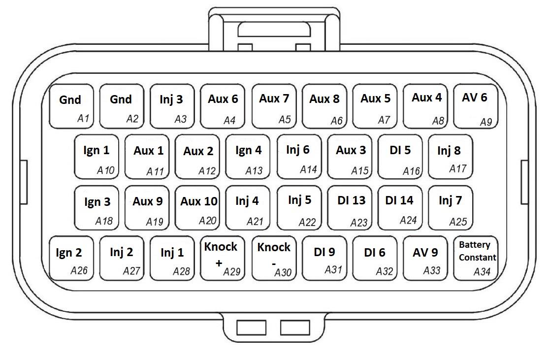
YXZ1000R Connector A — looking into the ECU connector.
| Pin | OEM Pin | Channel Name | Pin | OEM Pin | Channel Name |
|---|---|---|---|---|---|
| A1 | 35 | Power System Ground 1 | A18 | 52 | Ignition Coil Cyl 3 |
| A2 | 36 | Power System Ground 1 | A19 | 53 | Emtron User Output (e.g. DBW +) |
| A3 | 37 | Primary Injector Cyl 3 | A20 | 54 | Emtron User Output (e.g. DBW −) |
| A4 | 38 | Idle Stepper – W2 - A | A21 | 55 | Fuel Pump 1 |
| A5 | 39 | Idle Stepper – W1 - B | A22 | 56 | Radiator Fan Relay 1 |
| A6 | 40 | Idle Stepper – W2 - B | A23 | 57 | Hand Brake Switch |
| A7 | 41 | Idle Stepper – W1 - A | A24 | 58 | Brake Switch 1 |
| A8 | 42 | PVC Solenoid Output (Paddle ONLY) | A25 | 59 | Starter Relay Control |
| A9 | 43 | Emtron User Input | A26 | 60 | Ignition Coil Cyl 2 |
| A10 | 44 | Ignition Coil Cyl 1 | A27 | 61 | Primary Injector Cyl 2 |
| A11 | 45 | YXZ Differential Lock Relay 1 | A28 | 62 | Primary Injector Cyl 1 |
| A12 | 46 | YXZ Differential Lock Relay 2 | A29 | 63 | Emtron Knock 1+ Input |
| A13 | 47 | Seat Belt Pilot Lamp | A30 | 64 | Emtron Knock 1- Input |
| A14 | 48 | User Output 3 - Parking Brake Buzzer | A31 | 65 | Differential Servo Position 3 |
| A15 | 49 | Tacho - (Drive for EPS / Trans) | A32 | 66 | Clutch Switch (Non-paddle ONLY) |
| A16 | 50 | Start/Stop Switch | A33 | 67 | Trans ECU Current Feedback / Emtron User Input |
| A17 | 51 | User Output 2 - Air Induction Relay | A34 | 68 | Battery Constant Voltage |
Connector B: Signal / Power / Communications / Triggers / Knock
(15.0A Max continuous current - wire gauge dependant)
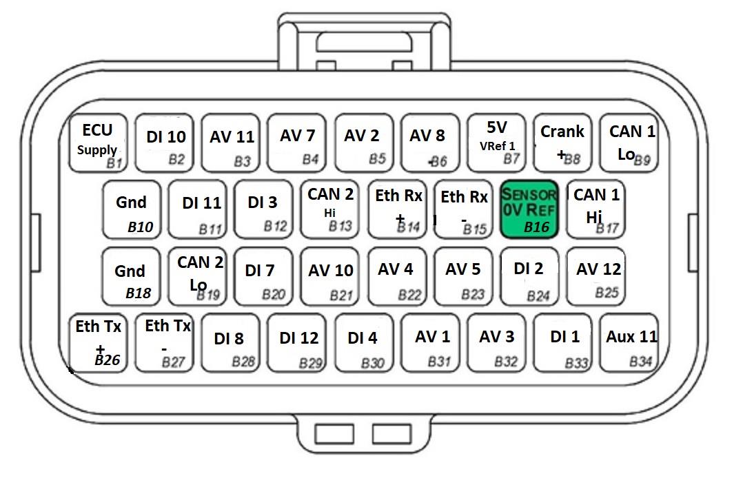
YXZ1000R Connector B — looking into the ECU connector.
| Pin | OEM Pin | Channel Name | Pin | OEM Pin | Channel Name |
|---|---|---|---|---|---|
| B1 | 1 | ECU 14V Supply | B18 | 18 | Control System Ground 2 |
| B2 | 2 | YXZ Differential Switch 12 | B19 | 19 | Emtron CAN 2 Low |
| B3 | 3 | YXZ Differential Lock Rotary Switch 1 | B20 | 20 | YXZ Differential Servo Position 1 |
| B4 | 4 | Engine Temperature | B21 | 21 | Neutral Switch |
| B5 | 5 | Manifold Pressure – Bank 1 (Cyl 1) | B22 | 22 | Gear Position Sensor (Non-paddle) |
| B6 | 6 | Inlet Air Temp | B23 | 23 | Lean Angle Sensor |
| B7 | 7 | Sensor 5V Power Source | B24 | 24 | Speed Sensor |
| B8 | 8 | Crank Position Sensor | B25 | 25 | YXZ Differential Lock Rotary Switch 2 |
| B9 | 9 | CAN Bus Low (OEM) | B26 | 26 | Emtron Ethernet Tx + |
| B10 | 10 | Control System Ground 1 | B27 | 27 | Emtron Ethernet Tx − |
| B11 | 11 | YXZ Differential Switch 1 | B28 | 28 | YXZ Differential Servo Position 2 |
| B12 | 12 | Battery Voltage Monitor | B29 | 29 | YXZ Seat Belt Switch |
| B13 | 13 | Emtron CAN 2 High | B30 | 30 | User DI (Ethanol/Switch/Analog) |
| B14 | 14 | Emtron Ethernet Rx + | B31 | 31 | Throttle Position 1 |
| B15 | 15 | Emtron Ethernet Rx − | B32 | 32 | Manifold Pressure |
| B16 | 16 | Sensor System Ground | B33 | 33 | Oil Pressure Switch |
| B17 | 17 | CAN Bus High (OEM) | B34 | 34 | Fan2 Relay (Paddle) |
7.1 Important Notes
Analog Sensor 0V Reference (Pin B16) — Connect directly to the 0V (Ground) pin on any low current analog sensor. DO NOT connect ECU pin B16 directly to the Engine Block or ECU Ground. DO NOT connect frequency-based sensors to these pins; the sensor 0V pin should be connected to the ECU ground.
WarningWARNING Replacing the MAP Sensor for Boosted applications. The MAP sensor located on Cylinder 1 is used to synchronise the engine — do not replace this MAP sensor with an alternative item, as replacement will result in loss of 720 sync and engine start. When shifting to a boosted application, the correct MAP sensor to replace is located on Cylinder 2 (Input Channel AV3 – Manifold Pressure).
8.0 Software
Emtron’s comprehensive Emtune tuning software is used to connect to the ECU (Windows 7-10, free licence, 0.5GB RAM, Ethernet IPV4). Tuning and data analysis, PC and ECU data logging, live pause and playback, advanced tuning functions, diagnostics and oscilloscope display.
9.0 Ordering Information
| Product | Part Number |
|---|---|
| Emtron YXZ ECU | 1609-252426 |
| Emtron Ethernet Tuning Cable (1.5m) | 553-15 |
| Emtron Communications Cable, Superseal to Emtron Connector 200mm | 533-02 |
Appendix A – YXZ1000R Series Ethernet Wiring
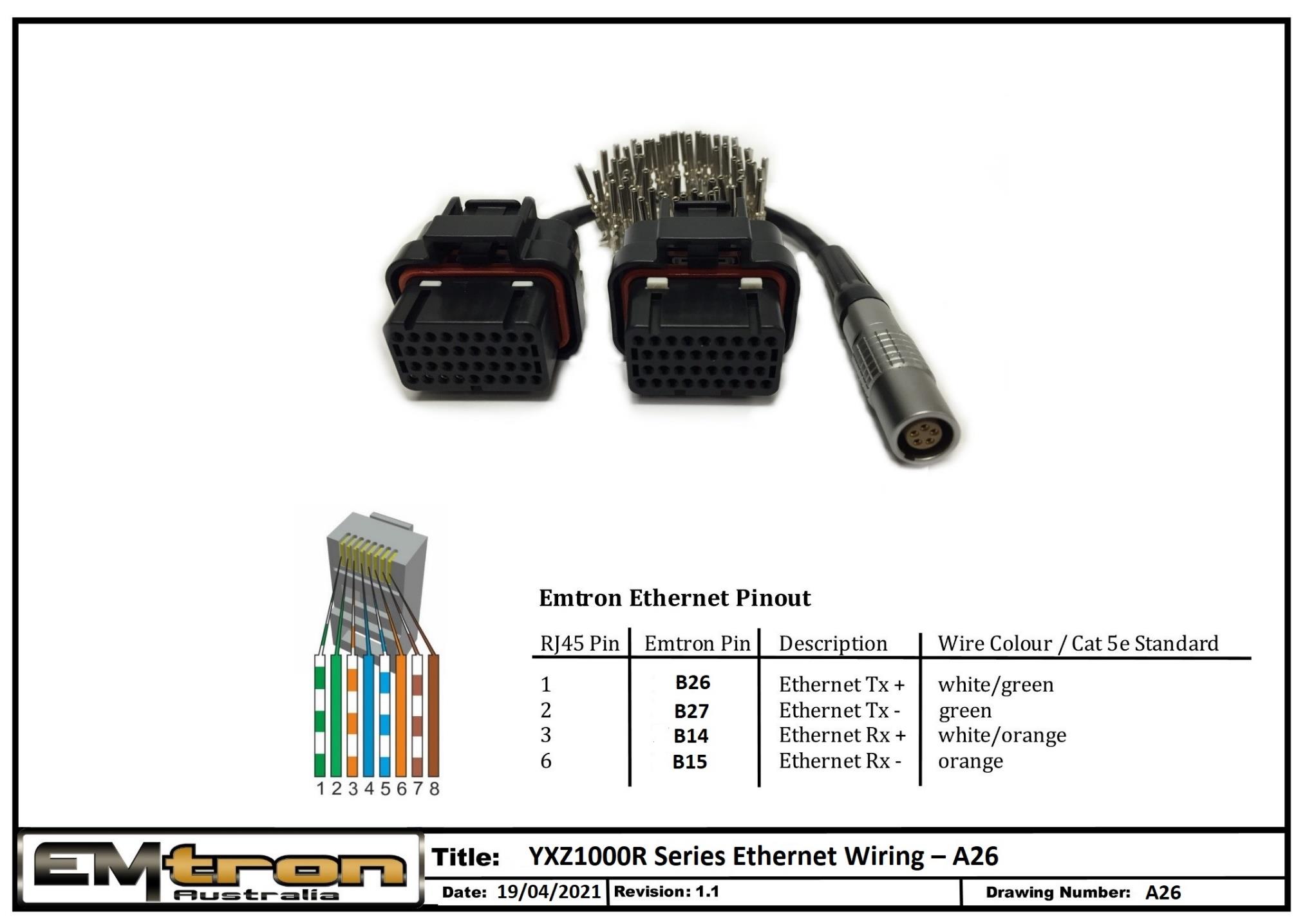
YXZ1000R Series Ethernet wiring / tuning cable pinout (drawing A26).