Shadow 8 ECU Datasheet
Emtron Shadow 8 ECU
1.0 General
The Shadow ECU range is built upon the outstanding foundation of the KV Series. This lightweight package is housed in a Billet Aluminium Enclosure and features a comprehensive 68-pin connector system. The Shadow ECU will support up to 8 Channels of fully sequential Fuel and Ignition. Up to 16MB permanent memory for on-board logging is available, DBW control, Knock control up to 2 channels using digital filter technology, and High-Speed USB C communications.
Functionality Count
- 8x Injection
- 8x Ignition
- 10x Analog Input
- 10x Digital Inputs
- 12x Auxiliary Outputs
- 2x CAN buses
- 2x Knock Inputs
- 2x GDI Pump Logic Control using Aux 11/12
- 1x DBW Control (Aux 9/10)
Power Supply
- Operating voltage: 6.0 to 22.0 Volts DC (ECU shutdowns at 24.0V)
- Operating current: 290mA at 14.0V (excluding sensor and load currents)
- Reverse battery protection via external fuse
- “Smart” battery transient protection
Operating Temperature
- Max operating range: -30 to 110°C (-22 to 230°F)
- Recommended operating range: -30 to 85°C (-22 to 185°F)
Physical
- Aluminium 6061 grade CNC billet enclosure
- Enclosure size 152 mm x 139 mm x 26 mm
- Weight: 520g
- Connector system: 68-way Super Seal waterproof connectors with gold plated contacts
- Pin diameter: 1 mm
- Current rating: maximum 15A per pin (wire gauge dependant)
- Connector A: 34 pin Key 1 Super Seal
- Connector B: 34 pin Key 2 Super Seal
Internal
- 100MHz Processor
- 16 MB ECU logging memory
- Over 1200 channels available
- 1Hz to 500Hz logging rate
2.0 Outputs
8x Port Injector Outputs — high ohm
- 70V clamping.
- Outputs can be used for ground switching, 6A Continuous, 10A Limit.
- All outputs are short circuit and over current protected.
- No Flywheel diodes (external diode(s) required for VVT control).
8x Ignition Outputs
- Adjustable TTL Ignition drive current (35mA or 70mA).
- Outputs can be used for ground switching, 1A Continuous, 3A Limit.
- All outputs are short circuit and over current protected.
- No Flywheel diodes (external diode(s) required for VVT control).
12x Auxiliary Outputs
- Variable Valve Timing (VVT) and Variable Valve Timing Electric (VTiE), Drive by Wire (DBW), dual boost control, gearshift solenoids, stepper motor and many more.
- All outputs have PWM control, maximum frequency = 10 kHz.
- Flywheel diodes integrated into all outputs.
- Auxiliary 1-8 Flywheel to the “Hot Supply” pin B1 connector B
- Auxiliary 9-12 Flywheel to the “Aux 9-12 Supply” pin B26 connector B
- All outputs are short circuit and over current protected.
Low Side Drivers
- Auxiliary 1-4: Low Side 4A continuous, 6A peak modulated, 8A limit.
- Auxiliary 5-8: Low Side 2.5A continuous, 4A peak modulated, 5A limit.
High Side Drivers
- Auxiliary 5-8: High Side 4A continuous, 8A limit.
Half Bridge Drivers
- Auxiliary 9-12: Half Bridge 5A continuous and 8A limit. Can be used as Low Side, High Side or together in H-bridge configuration for DC motor control (DBW).
1x Shield Output
- Connection for Trigger and Knock shielded cables. Short to battery protection.
3.0 Inputs
10x Analog Voltage/Temperature Inputs
- Fully configurable including custom calibrations.
- Switchable 1k ohm pull-up resistors on ANV 7-10.
- Accepts a 0.0 - 5.000V Analog input. Resolution is 1.22mV (12-Bit).
- Input Impedance 100k Ohms to ground.
10x Digital/Speed Inputs/Switched Inputs/Analog Inputs
- Frequency Range from 0.0Hz up to 5.0kHz on channels 1-4.
- Magnetic and Hall effect sensor compatible on DI 1-4, with programmable frequency-based arming threshold control, range 0.0 - 12.0V.
- Hall effect sensor only on DI 5-8 with fixed frequency-based arming thresholds (1.45V).
- Wheel speed, output shaft speed and other frequency-based signals.
- VVT position(s) up to 4 channels available on DI 1-4, Magnetic and Hall effect sensor compatible.
- DI1-10 all have ON/OFF switched control: AC request, Launch enable, Cruise switch, table control switching etc with arming threshold control, range 0.0 - 20.0V.
- DI1-10 channels ALL accept a 0.0 - 20.0V Analog input voltage. Resolution is 4.88mV (10-Bit).
- Switchable 4k7 ohm pull-up resistors on DI1-8 channels to 10V.
- Maximum input signal amplitude +/- 50V.
- Input Impedance 110k ohms to ground.
2x Knock Inputs
- 2 Independent knock input channels.
- Digital Knock Integrated Circuit Technology with programmable Centre Frequency, Gain and Integrator Time Constant.
- Centre frequency configurable from 1kHz - 20kHz.
- Gain control from 0.1 to 2.0.
- Cylinder selectable knock input.
- Knock control available on ALL Ignition modes (Direct, Wasted, Distributor etc).
2x Crank Index and Sync Engine Decoding Inputs
- Magnetic and Hall effect sensor compatible with programmable trigger edge(s)
- “True” zero crossing detection on magnetic signals for precise engine position decoding.
- Programmable independent arming threshold control from 0.1V to 12.0V
- Switchable 4k7 ohm pull-up resistor to 5V
- OEM patterns supported.
- Maximum input signal amplitude +/- 80V
- Input Impedance 100k ohms to ground.
1x Ignition Switch Input / DI10
- 6.0 - 20.0V input used for EFI Relay Control. (With input > 6V the Internal Hold-power system turns the ECU ON using the HOT Supply). Refer to the document “Shadow 8 Power Supply Wiring”.
4.0 Voltage and Ground Supplies
1x ECU Supply Input
- 15.0A Max (pin limited).
- 6V - 22.0V Range.
- Supplies ECU power.
- Supplies power to Auxiliary 1-8 High Side Drivers.
1x Auxiliary 9-12 Supply Input
- 15.0A Max (pin limited).
- Power supply for Auxiliary channels 9-12. (See “Shadow Series Power Distribution Wiring” for more information on how this should be wired. Refer Appendix B).
1x Battery Constant Supply Input
- 15.0A Max (pin limited).
- ECU MUST always have constant power. Used by Auxiliary Flywheel diodes and for the ECU automated shutdown procedure.
1x 5.0V Sensor Supply
- 5V Vref1 output current 250mA.
1x 8.0V Sensor Supply
- Output current 400mA.
2x ECU Main Grounds
- 15.0A per pin, total 30A.
1x Sensor 0V Reference
- Analog Sensor 0V Reference with short to battery protection (See note in Section 6.1).
NoteNOTE The Sensor 0V Reference pin(s) is a specialised ground output for all Analog sensors. Connect direct to the sensor 0V pin, DO NOT connect to the Engine Block or ECU Ground.
5.0 Communications
- 1x High Speed USB for tuning software connection.
- 2x CAN 2.0B 1Mbps / 6 Channels per node, total 128 messages.
6.0 Shadow 8 Pinout
Connector A: Signal / Power / Communications / Triggers / Knock
(15.0A Max continuous current - wire gauge dependant)
| Pin | Channel Name | Pin | Channel Name |
|---|---|---|---|
| A1 | ECU Supply | A18 | Analog Voltage 6 |
| A2 | Sensor 8.0V Sensor Supply | A19 | Analog Voltage 7 |
| A3 | Sensor 5.0V Sensor Supply | A20 | Analog Voltage 8 |
| A4 | 0V Analog Reference | A21 | Analog Voltage 9 |
| A5 | Crank Position Sensor | A22 | Analog Voltage 10 |
| A6 | Sync Position Sensor | A23 | CAN Bus 1 Low |
| A7 | Trigger Ground | A24 | Knock 2 +ve |
| A8 | Shield | A25 | Knock 2 -ve |
| A9 | Ground 1 | A26 | Digital Input 1 |
| A10 | Analog Voltage 1 | A27 | Digital Input 2 |
| A11 | Analog Voltage 2 | A28 | Digital Input 3 |
| A12 | Analog Voltage 3 | A29 | Digital Input 4 |
| A13 | Analog Voltage 4 | A30 | Digital Input 5 |
| A14 | Analog Voltage 5 | A31 | Digital Input 6 |
| A15 | CAN Bus 1 High | A32 | CAN Bus 2 High |
| A16 | Knock 1 +ve | A33 | CAN Bus 2 Low |
| A17 | Knock 1 -ve | A34 | Ground 2 |
Connector B: Injection / Ignition / Auxiliary Outputs
(15.0A Max continuous current - wire gauge dependant)
| Pin | Channel Name | Pin | Channel Name |
|---|---|---|---|
| B1 | Battery Constant (HOT) Supply | B18 | Digital Input 7 |
| B2 | Injector Cylinder 1 | B19 | Digital Input 8 |
| B3 | Injector Cylinder 2 | B20 | Digital Input 9 |
| B4 | Injector Cylinder 3 | B21 | Digital Input 10 / Ignition Switch |
| B5 | Injector Cylinder 4 | B22 | Aux Output 9 |
| B6 | Injector Cylinder 5 | B23 | Aux Output 10 |
| B7 | Injector Cylinder 6 | B24 | Aux Output 11 |
| B8 | Injector Cylinder 7 | B25 | Aux Output 12 |
| B9 | Injector Cylinder 8 | B26 | Aux 9-12 Power Supply |
| B10 | Aux Output 1 | B27 | Ignition TTL Cylinder 1 |
| B11 | Aux Output 2 | B28 | Ignition TTL Cylinder 2 |
| B12 | Aux Output 3 | B29 | Ignition TTL Cylinder 3 |
| B13 | Aux Output 4 | B30 | Ignition TTL Cylinder 4 |
| B14 | Aux Output 5 | B31 | Ignition TTL Cylinder 5 |
| B15 | Aux Output 6 | B32 | Ignition TTL Cylinder 6 |
| B16 | Aux Output 7 | B33 | Ignition TTL Cylinder 7 |
| B17 | Aux Output 8 | B34 | Ignition TTL Cylinder 8 |
Digital Inputs Summary
| Pin | Channel Name | Pullup Control | Type |
|---|---|---|---|
| A26 | Digital Input 1 (Wheel Speed) | Yes | Mag or Hall 0-5kHz, OR Analog 0-20V, Adj Arm |
| A27 | Digital Input 2 (Wheel Speed) | Yes | Mag or Hall 0-5kHz, OR Analog 0-20V, Adj Arm |
| A28 | Digital Input 3 (Wheel Speed) | Yes | Mag or Hall 0-5kHz, OR Analog 0-20V, Adj Arm |
| A29 | Digital Input 4 (Wheel Speed) | Yes | Mag or Hall 0-5kHz, OR Analog 0-20V, Adj Arm |
| A30 | Digital Input 5 | Yes | Hall 0-5kHz, Analog 0-20V, Fixed Arm 1.45V, SENT Protocol compatible |
| A31 | Digital Input 6 | Yes | Hall 0-5kHz, Analog 0-20V, Fixed Arm 1.45V, SENT Protocol compatible |
| B18 | Digital Input 7 | Yes | Hall 0-5kHz, Analog 0-20V, Fixed Arm 1.45V, SENT Protocol compatible |
| B19 | Digital Input 8 | Yes | Hall 0-5kHz, Analog 0-20V, Fixed Arm 1.45V, SENT Protocol compatible |
| B20 | Digital Input 9 | No Pullup | Analog 0-20V |
| B21 | Digital Input 10 / Ignition Switch | No Pullup | Analog 0-20V |
Auxiliary Output Summary
| Pin | Channel Name | Drive Type | Mode | Description |
|---|---|---|---|---|
| B10 | Aux Output 1 | LS Only Inductive or Resistive | ON/OFF or PWM | Relay or Solenoid |
| B11 | Aux Output 2 | LS Only Inductive or Resistive | ON/OFF or PWM | Relay or Solenoid |
| B12 | Aux Output 3 | LS Only Inductive or Resistive | ON/OFF or PWM | Relay or Solenoid |
| B13 | Aux Output 4 | LS Only Inductive or Resistive | ON/OFF or PWM | Relay or Solenoid |
| B14 | Aux Output 5 | LS or HS Inductive or Resistive | ON/OFF or PWM | Relay or Solenoid |
| B15 | Aux Output 6 | LS or HS Inductive or Resistive | ON/OFF or PWM | Relay or Solenoid |
| B16 | Aux Output 7 | LS or HS Inductive or Resistive | ON/OFF or PWM | Relay or Solenoid |
| B17 | Aux Output 8 | LS or HS Inductive or Resistive | ON/OFF or PWM | Relay or Solenoid |
| B22 | Aux Output 9 | Half Bridge DBW + | PWM | Engine Main Throttle |
| B23 | Aux Output 10 | Half Bridge DBW - | PWM | Engine Main Throttle |
| B24 | Aux Output 11 | Half Bridge | ON/OFF or PWM | Relay or Solenoid or GDI Pump Ctrl Signal |
| B25 | Aux Output 12 | Half Bridge | ON/OFF or PWM | Relay or Solenoid or GDI Pump Ctrl Signal |
Analog Input Pull-up Summary
| Pin | Channel Name | Pullup Control |
|---|---|---|
| A10 | Analog Input Channel 1 | No |
| A11 | Analog Input Channel 2 | No |
| A12 | Analog Input Channel 3 | No |
| A13 | Analog Input Channel 4 | No |
| A14 | Analog Input Channel 5 | No |
| A18 | Analog Input Channel 6 | No |
| A19 | Analog Input Channel 7 | Yes |
| A20 | Analog Input Channel 8 | Yes |
| A21 | Analog Input Channel 9 | Yes |
| A22 | Analog Input Channel 10 | Yes |
6.1 Important Notes
Analog Sensor 0V Reference (Pin A4)
This pin should be connected directly to the 0V (Ground) pin on any low current Analog sensor, for example Pressure or Temperature.
- DO NOT connect the ECU pin A4 directly to the Engine Block or ECU Ground. These are dedicated and specialised ground outputs for all Analog channels and should be connected directly to the sensor.
- DO NOT connect frequency-based sensors to these pins, for example, an Ethanol content sensor. Frequency based sensor 0V pins should be connected to the ECU ground.
Aux 9-12 (Half Bridge) Driver Power Supply Input (Pin B26)
Pin B26 is a dedicated power supply for Auxiliary Channels 9-12. Power must be supplied to this pin for these channels to operate correctly. In non-DBW (Drive by Wire) applications the ECU Supply power can be shared, assuming the wire gauge has a sufficient rating for the current demand. In DBW applications power to this pin MUST come from an ECU controlled DBW Relay.
Battery Constant Supply Input (Pin B1)
- Pin B1 should ALWAYS be connected to a constant 12V supply. (NOTE: The ECU draws zero current once completely shut down.)
- ALL Auxiliary flywheel control is directed to this pin.
- Constant power to this pin allows the ECU to control its power-down sequence. See “Shadow Series Power Distribution Wiring” for more information on how this should be wired and configured. Refer Appendix B.
Ignition TTL Outputs
WarningWARNING DO NOT connect these outputs directly to a coil. These Outputs are TTL or 0 – 7V which are designed to drive the input of an Ignitor. Connection directly to a coil will permanently damage the ECU!!
7.0 Software
Comprehensive Emtune tuning software is used to connect to the ECU.
- Microsoft Windows™ 7-11 compatible
- Free licence
- Memory requirements: 0.5GB RAM
- ECU connection using USB C
- Tuning and data analysis
- PC and ECU data logging
- Live pause and data playback
- Advanced tuning functions
- Diagnostics
8.0 Ordering Information
| Product | Part Number |
|---|---|
| Emtron Shadow ECU | 1908-082 |
| Emtron USB Tuning Cable (1.5m) |
Appendix A – Shadow 8 ECU Pinout Drawing
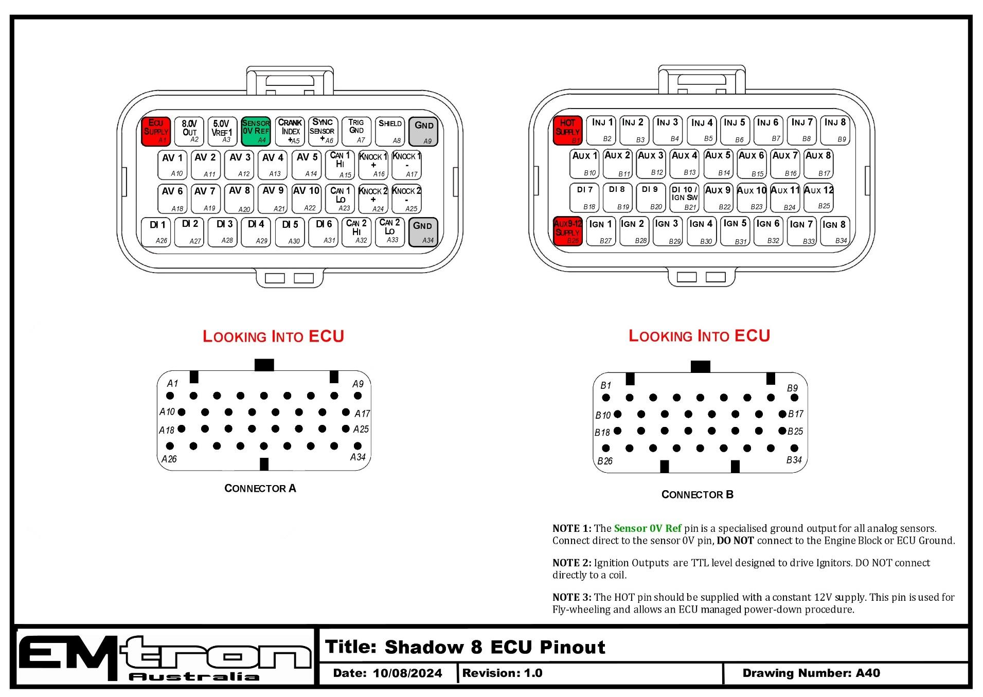
Shadow 8 ECU pinout — Connector A (signal/power) and Connector B (injection/ignition/aux), looking into ECU. Note the Sensor 0V Ref ground, the TTL ignition outputs, and the constant HOT supply requirement.
Appendix B – Shadow Series ECU Wiring
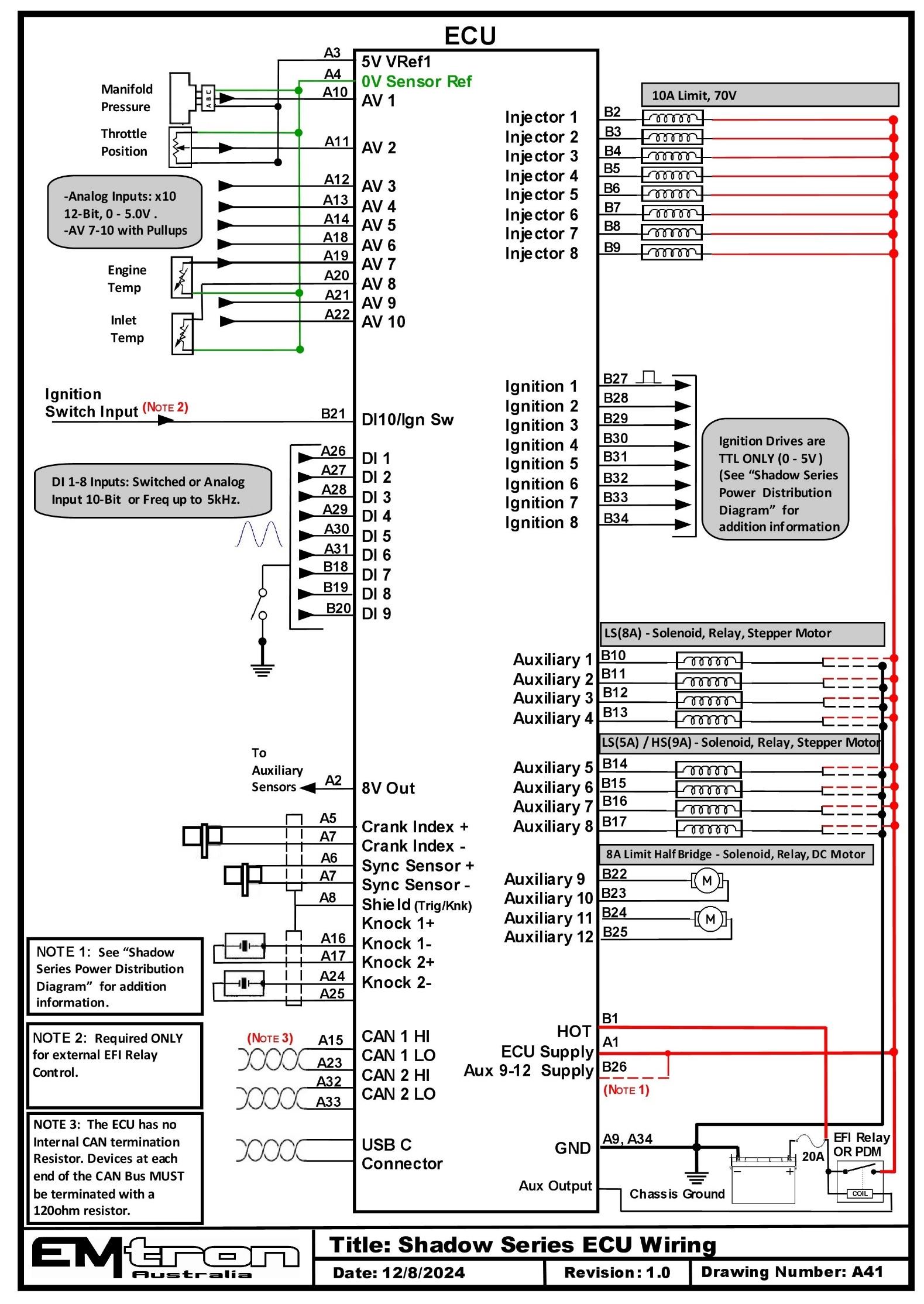
Shadow Series ECU typical wiring (drawing A41).