SL6 ECU Datasheet
Emtron SL6 ECU
1.0 General
Emtron’s SL Series is built upon the outstanding foundation of the KV Series and features the same processing power and logging capacity. This lightweight package is housed in a Billet Aluminium Enclosure and features a 68-pin connector system which is still a very high I/O count. The SL6 ECU will support up to 8 Channels of fully sequential Fuel and Ignition. Up to 32MB permanent memory for on-board logging is available, 4-channel oscilloscope function, DBW control, Knock control up to 2 channels using digital filter technology, High Speed Ethernet communications and 3-axis G-force sensing to name a few.
Power Supply
- Operating voltage: 6.0 to 22.0 Volts DC (ECU shutdowns at 24.0V)
- Operating current: 290mA at 14.0V (excluding sensor and load currents)
- Reverse battery protection via external fuse
- “Smart” battery transient protection
Operating Temperature
- Max operating range: -30 to 110°C (-22 to 230°F)
- Recommended operating range: -30 to 85°C (-22 to 185°F)
Physical
- Aluminium 6061 grade CNC billet enclosure
- Enclosure size 120 mm x 130 mm x 27 mm
- Weight: 470g
- Connector system: 68-way Super Seal waterproof connectors with gold plated contacts
- Pin diameter: 1 mm
- Current rating: maximum 15A per pin (wire gauge dependant)
- Connector A: 34 pin Key 2 Super Seal
- Connector B: 34 pin Key 1 Super Seal
Internal
- Dual 100MHz processors
- 500Mb DDR RAM (0.5Gb)
- 32MB ECU logging memory
- Over 1200 channels available
- 1Hz to 500Hz logging rate
- Oscilloscope 4-channel function with 32MB storage
- Sampling at 100k samples/second
- Includes Crank Index and Sync sensor inputs
- Includes Digital Inputs 1-4
- On-Board barometric pressure sensor
- Range 40 - 115.0 kPa
- 3-Axis accelerometer
- 16-Bit resolution
- +2g/+4g/+8g dynamically selectable full-scale
- Output data rate 500Hz
2.0 Outputs
6x Port Injector Outputs — high ohm
- 70V clamping
- Outputs can be used for ground switching, 6A Continuous, 10A Limit
- All outputs are short circuit and over current protected
- No Flywheel diodes (external diode(s) required for VVT control)
6x Ignition Outputs
- Adjustable TTL Ignition drive current (35mA or 70mA)
- Outputs can be used for ground switching, 1A Continuous, 3A Limit
- All outputs are short circuit and over current protected
- No Flywheel diodes (external diode(s) required for VVT control)
10x Auxiliary Outputs
- Variable Valve Timing (VVT) and Variable Valve Timing Electric (VTiE), Drive by Wire (DBW), dual boost control, gearshift solenoids, stepper motor and many more.
- All outputs have PWM control, maximum frequency = 15 kHz
- Flywheel diodes integrated into all outputs
- Auxiliary 1-8 Flywheel to the “ECU Supply” pin B1 connector B
- Auxiliary 9-10 Flywheel to the “ECU 9-12 Supply” pin A34 connector A
- All outputs are short circuit and over current protected
Low Side Drivers
- Auxiliary 1-4: Low Side 4A continuous, 6A peak modulated, 8A limit
- Auxiliary 5-8: Low Side 2.5A continuous, 4A peak modulated, 5A limit
High Side Drivers
- Auxiliary 1-8: High Side 4A continuous, 9A limit
Half Bridge Drivers
- Auxiliary 9-10: Half Bridge 5A continuous and 8A limit. Can be used as Low Side, High Side or together in H-bridge configuration for DC motor control (DBW)
1x EFI Relay Output
- Low Side Driver for relay control. Current limited to 200mA (Output will switch ON when Ignition Switch Input (B4) is greater than 4V)
1x Shield Output
- Connection for Trigger and Knock shielded cables. Short to battery protection
3.0 Inputs
10x Analog Voltage/Temperature Inputs
- Fully configurable including custom calibrations
- Switchable 1k ohm pull-up resistors on ANV 7-10
- Accepts a 0.0 - 5.000V analog input. Resolution is 1.22mV (12-Bit)
- Input Impedance 100k Ohms to ground
6x Digital/Speed Inputs/Switched Inputs
- Frequency range from 0.0Hz up to 30.0kHz on all 6 channels
- Magnetic and Hall effect sensor compatible on DI 1-4 with programmable trigger edge(s)
- Hall effect sensor only on DI 5-6 with programmable trigger edge(s)
- Independent programmable frequency-based arming threshold control, range 0.0 - 12.0V on DI 1-4
- Fixed frequency-based arming thresholds on DI 5-6. Rising = 1.2V, Falling = 1.0V.
- Wheel speed, output shaft speed and other frequency-based signals
- VVT position(s) up to 4 channels available on DI 1-4.
- ON/OFF switched inputs: AC request, Launch enable, cruise switch, table control switching etc with arming threshold control, range 0.0 - 20.0V
- Accepts a 0.0 - 20.0V analog input. Resolution is 4.88mV (10-Bit)
- Switchable 4k7 ohm pull-up resistors on all 6 channels to 10V
- Maximum input signal amplitude +/- 80V
2x Knock Inputs
- 2 Independent knock input channels
- Using Bosch, Digital Knock Integrated Circuit Technology with programmable digital filter coefficients
- Center frequency configurable from 500Hz - 25kHz
- Bandwidth window from 100Hz - 5kHz
- Digital filter window; Hamming or Blackman
- Gain control (x1, x2, x4, x8)
- Cylinder selectable knock input
- Knock control available on ALL Ignition modes (Direct, Wasted, Distributor etc)
1x Dedicated Ignition Switch Input
- 6.0 - 20.0V input used for EFI Relay Control. (With input > 4V the EFI Relay output (D9) will switch ON)
2x Crank Index and Sync Engine Decoding Inputs
- Magnetic and Hall effect sensor compatible with programmable trigger edge(s)
- “True” zero crossing detection on magnetic signals for precise engine position decoding.
- Programmable independent arming threshold control from 0.1V to 12.0V
- Switchable 4k7 ohm pull-up resistor to 5V
- OEM patterns supported
- Maximum input signal amplitude +/- 80V
- Input Impedance 39k ohms to ground
4.0 Voltage and Ground Supplies
1x ECU Supply Input
- 15.0A Max (pin limited)
- 6V - 22.0V Range
- Supplies ECU power
- Supplies power to Auxiliary 1-8 High Side Drivers
1x Auxiliary 9-10 Supply Input
- 15.0A Max (pin limited)
- Power supply for Auxiliary channels 9-10. (See the SL Series Power Distribution Wiring for more information on how this should be wired. Also see Section 6.1)
1x 5.0V Sensor Supply
- 5V Vref1 output current 250mA
1x 8.0V Sensor Supply
- Output current 400mA
2x ECU Main Grounds
- 15.0A per pin, total 30A
1x Sensor 0V Reference
- Analog Sensor 0V Reference with short to battery protection (See note in Section 6.1)
NoteNOTE The Sensor 0V Reference pin(s) are specialised ground outputs for all analog sensors. Connect direct to the sensor 0V pin, DO NOT connect to the Engine Block or ECU Ground.
5.0 Communications
- 1x High Speed Ethernet 100Mbps for tuning software connection
- 2x CAN 2.0B 1Mbps / 6 Channels per node, total 128 messages
6.0 SL6 Pinout
Connector A: Injection / Ignition / Auxiliary Outputs
(15.0A Max continuous current - wire gauge dependant)
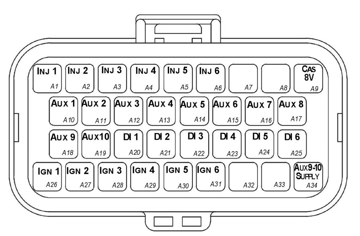
SL6 Connector A — looking into ECU connector.
| Pin | Channel Name | Pin | Channel Name |
|---|---|---|---|
| A1 | Injection Channel 1 | A18 | Auxiliary Output 9 |
| A2 | Injection Channel 2 | A19 | Auxiliary Output 10 |
| A3 | Injection Channel 3 | A20 | Digital Input 1 |
| A4 | Injection Channel 4 | A21 | Digital Input 2 |
| A5 | Injection Channel 5 | A22 | Digital Input 3 |
| A6 | Injection Channel 6 | A23 | Digital Input 4 |
| A7 | NC | A24 | Digital Input 5 |
| A8 | NC | A25 | Digital Input 6 |
| A9 | Sensor Supply 8V | A26 | Ignition Channel 1 |
| A10 | Auxiliary Output 1 | A27 | Ignition Channel 2 |
| A11 | Auxiliary Output 2 | A28 | Ignition Channel 3 |
| A12 | Auxiliary Output 3 | A29 | Ignition Channel 4 |
| A13 | Auxiliary Output 4 | A30 | Ignition Channel 5 |
| A14 | Auxiliary Output 5 | A31 | Ignition Channel 6 |
| A15 | Auxiliary Output 6 | A32 | NC |
| A16 | Auxiliary Output 7 | A33 | NC |
| A17 | Auxiliary Output 8 | A34 | Auxiliary Output 9-10, 14V Supply |
NC = No Connect
Connector B: Signal / Power / Communications / Triggers / Knock
(15.0A Max continuous current - wire gauge dependant)
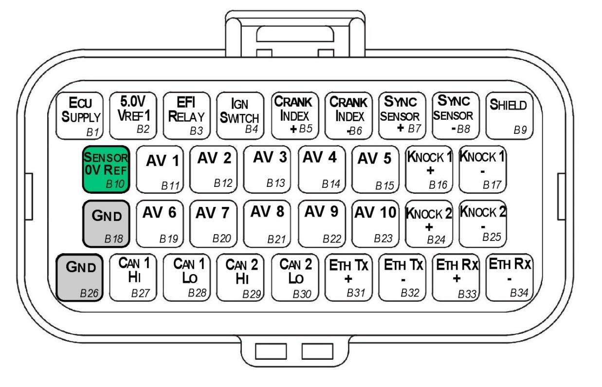
SL6 Connector B — looking into ECU connector.
| Pin | Channel Name | Pin | Channel Name |
|---|---|---|---|
| B1 | ECU 14V Supply | B18 | ECU Ground |
| B2 | Sensor Supply Vref1: 5.0V | B19 | Analog Input Channel 6 |
| B3 | EFI Relay Output (Low Side 200mA) | B20 | Analog Input Channel 7 |
| B4 | Ignition Switch Input | B21 | Analog Input Channel 8 |
| B5 | Crank Index Sensor + | B22 | Analog Input Channel 9 |
| B6 | Crank Index Sensor - | B23 | Analog Input Channel 10 |
| B7 | Sync Sensor + | B24 | Knock 2 + |
| B8 | Sync Sensor - | B25 | Knock 2 - |
| B9 | Shield (Crank/Sync/Knock) | B26 | ECU Ground |
| B10 | Analog Sensor 0V Reference | B27 | CAN 1H |
| B11 | Analog Input Channel 1 | B28 | CAN 1L |
| B12 | Analog Input Channel 2 | B29 | CAN 2H |
| B13 | Analog Input Channel 3 | B30 | CAN 2L |
| B14 | Analog Input Channel 4 | B31 | Ethernet Tx + |
| B15 | Analog Input Channel 5 | B32 | Ethernet Tx - |
| B16 | Knock 1 + | B33 | Ethernet Rx + |
| B17 | Knock 1 - | B34 | Ethernet Rx - |
6.1 Important Notes
Analog Sensor 0V Reference (Pin B10)
This pin should be connected directly to the 0V (Ground) pin on any low current analog sensor, for example Pressure or Temperature.
- DO NOT connect the ECU pin B10 directly to the Engine Block or ECU Ground. These are dedicated and specialised ground outputs for all analog channels and should be connected directly to the sensor.
- DO NOT connect frequency-based sensors to these pins; for example, an Ethanol content sensor. The sensor 0V pin should be connected to the ECU ground.
Half Bridge Driver Power Supply Input (Pin A34)
Pin A34 is a dedicated power supply for Auxiliary Channels 9-10. Power must be supplied to this pin for these channels to operate correctly. In non-DBW (Drive by Wire) applications the ECU Supply power can be shared, assuming the wire gauge has a sufficient rating for the current demand. In DBW applications power to this pin MUST come from an ECU controlled DBW Relay.
7.0 Software
Emtron’s comprehensive Emtune tuning software is used to connect to the ECU.
- Microsoft Windows™ 7-10 compatible
- Free licence
- Memory requirements: 0.5GB RAM
- ECU connection using Ethernet, IPV4 protocol
- Tuning and data analysis
- PC and ECU data logging
- Live pause and data playback
- Advanced tuning functions
- Diagnostics
- Oscilloscope display
8.0 Ordering Information
| Product | Part Number |
|---|---|
| Emtron SL6 ECU | 1912-062 |
| Emtron Ethernet Tuning Cable (1.5m) | 553-15 |
| Emtron Communications Cable, Superseal to Emtron Connector 200mm | 533-02 |
Appendix A – SL6 ECU Pinout Drawing
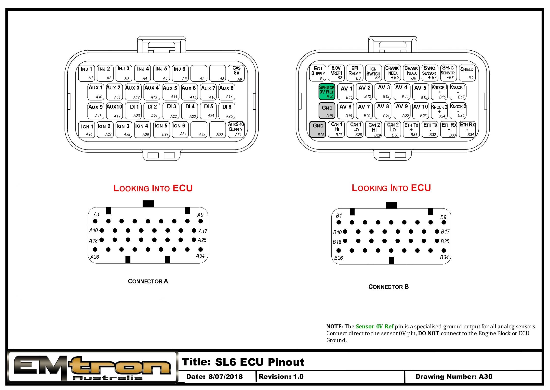
SL6 ECU pinout — Connector A and Connector B, looking into ECU. The Sensor 0V Ref pin is a specialised ground output for all analog sensors; connect direct to the sensor 0V pin.
Appendix B – SL Series ECU Wiring
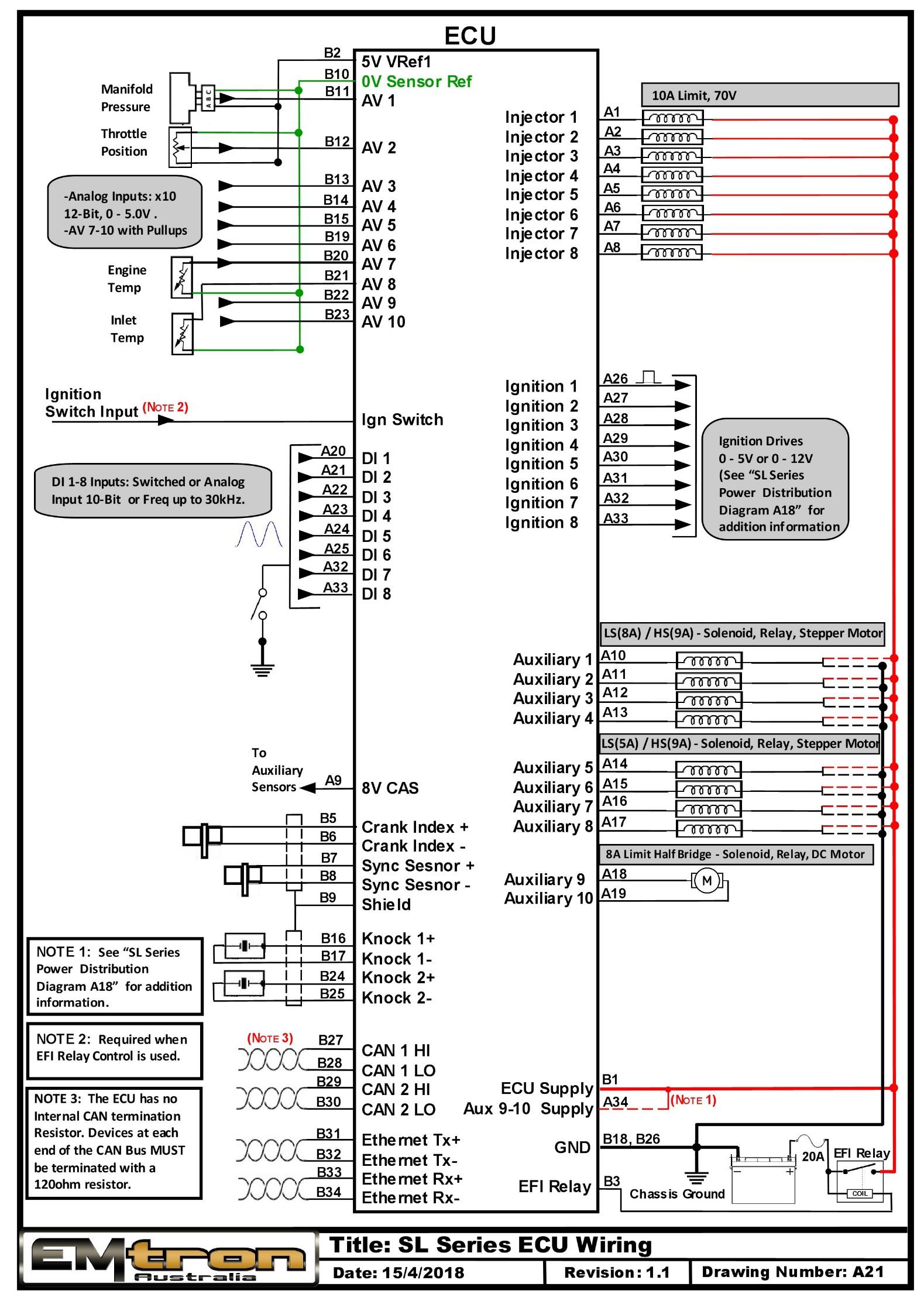
SL Series ECU typical wiring (drawing A21).
Appendix C – SL Series Ethernet Wiring
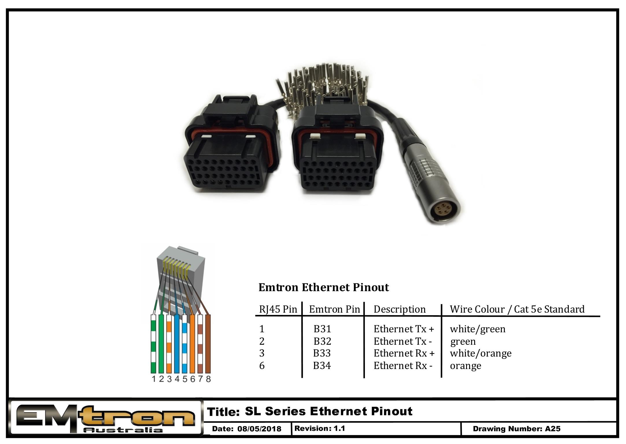
SL Series Ethernet pinout / tuning cable wiring (drawing A25).