YXZ1000R Plugin ECU Datasheet
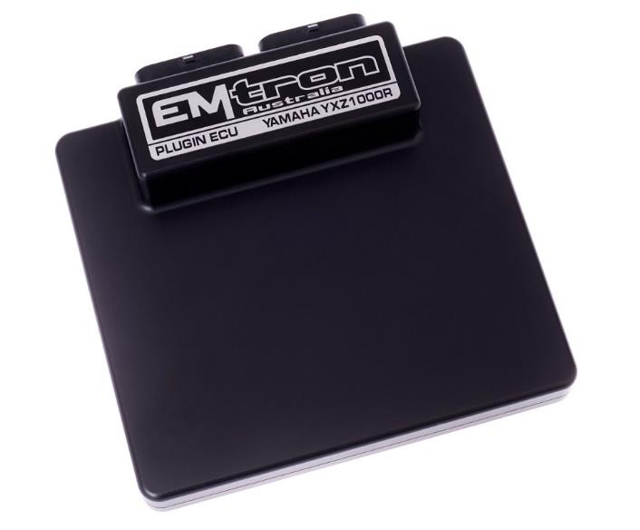
Emtron YXZ1000R Plugin ECU.
1.0 General
Emtron’s YXZ1000R Plugin ECU is built upon the outstanding foundation of the SL Series and features the same processing power and logging capacity. This lightweight package is housed in a Billet Aluminium Enclosure, designed to be plugged into the OEM harness to allow for a true “Plug and Play” install. As few inputs & outputs remain unused for User definition, CAN Bus 2 is made available providing additional I/O expandability. Other features include up to 32MB permanent memory for on-board logging, 4-channel oscilloscope function, DBW control, Knock control using digital filter technology, High Speed Ethernet communications and 3-axis G-force sensing.
Power Supply
- Operating voltage: 6.0 to 22.0 Volts DC (ECU shutdowns at 24.0V)
- Operating current: 290mA at 14.0V (excluding sensor and load currents)
- Reverse battery protection via external fuse
- “Smart” battery transient protection
Operating Temperature
- Max operating range: -30 to 110°C (-22 to 230°F)
- Recommended operating range: -30 to 85°C (-22 to 185°F)
Physical
- Aluminium 6061 grade CNC billet enclosure
- Enclosure size 120 × 130 × 27 mm
- Weight: 470g
- Connector system: 68-way Super Seal waterproof connectors with gold plated contacts (1mm pin, max 15A per pin). Connector A: 34 pin Key 2 Super Seal; Connector B: 34 pin Key 1 Super Seal.
Internal
- Dual 100MHz processors
- 500Mb DDR RAM (0.5Gb)
- 32MB ECU logging memory — over 1200 channels available, 1Hz to 500Hz logging rate
- Oscilloscope 4-channel function with 32MB storage (100k samples/second; includes Crank Index, Sync and Digital Inputs 1-4)
- On-Board barometric pressure sensor (40 - 115.0 kPa)
- 3-Axis accelerometer (16-Bit, +2g/+4g/+8g selectable, 500Hz output)
2.0 Outputs
8x Port Injector Outputs — high ohm
- 70V clamping; ground switching 6A Continuous, 10A Limit; short circuit & over current protected; no flywheel diodes (external diode(s) required for VVT control).
4x Ignition Outputs
- 3× Ignition outputs for direct-to-coil wiring (IGBT)
- 1× Adjustable TTL Ignition drive current (35mA or 70mA)
- Ground switching 1A Continuous, 3A Limit; short circuit & over current protected; no flywheel diodes.
10x Auxiliary Outputs
- Drive by Wire (DBW), dual boost control, gearshift solenoids, stepper motor and more. PWM control, max 15 kHz. Flywheel diodes integrated (Aux 1-8 to ECU Supply pin B1; Aux 9-10 to ECU 9-12 Supply pin A34). Short circuit & over current protected.
- Low Side: Aux 1-4 = 4A continuous / 6A peak / 8A limit; Aux 5-8 = 2.5A continuous / 4A peak / 5A limit.
- High Side: Aux 1-8 = 4A continuous, 9A limit.
- Half Bridge: Aux 9-10 = 5A continuous, 8A limit (Low Side, High Side or paired H-bridge for DBW).
3.0 Inputs
12x Analog Voltage/Temperature Inputs — Fully configurable with custom calibrations; switchable 1k ohm pull-ups on ANV 7-12; 0.0 - 5.000V, 1.22mV (12-Bit); 100k Ohms to ground.
14x Digital/Speed/Switched Inputs — 0.0Hz to 30.0kHz on channels 1-8; Magnetic + Hall on DI 1-4 (programmable trigger edge, adjustable arming 0.0-12.0V); Hall only on DI 5-8 (fixed arming Rising 1.2V / Falling 1.0V); ON/OFF switched inputs; 0.0-20.0V analog, 4.88mV (10-Bit); switchable 4k7 pull-ups on all 12 channels to 10V; max ±80V.
1x Knock Input — 1 independent channel; Bosch Digital Knock IC with programmable filter coefficients; centre frequency 500Hz - 25kHz; bandwidth 100Hz - 5kHz; Hamming or Blackman window; gain x1/x2/x4/x8; cylinder selectable; available on ALL ignition modes.
1x Crank Index Engine Decoding Input — OEM Magnetic sensor compatible; “True” zero crossing detection; programmable arming 0.1V to 12.0V; OEM pattern supported; max ±80V; 39k ohms to ground.
4.0 Voltage and Ground Supplies
- 2x ECU Supply Input — 15.0A Max (pin limited), 6V-22.0V, supplies ECU power and Auxiliary 1-10 High Side Drivers. (1× Dedicated battery power supply, 1× Ignition Power Supply.)
- 1x 5.0V Sensor Supply — 5V Vref1, 250mA.
- 4x ECU Main Grounds — 15.0A per pin, total 60A.
- 1x Sensor 0V Reference — Analog Sensor 0V Reference with short to battery protection.
NoteNOTE The Sensor 0V Reference pin(s) are specialised ground outputs for all analog sensors. Connect direct to the sensor 0V pin, DO NOT connect to the Engine Block or ECU Ground.
5.0 ECU Channel Assignment
Injection
| ECU Channel | Function |
|---|---|
| Injection 1-3 | Primary Injector Cylinder 1-3 |
| Injection 4 | Fuel Pump 1 (+Main relay) |
| Injection 5 | Cooling Fan 1 |
| Injection 6 | User Output 3 - Park Belt Buzzer |
| Injection 7 | Start Relay Control |
| Injection 8 | User Output 2 - Air Induction Relay |
Ignition
| ECU Channel | Function |
|---|---|
| Ignition 1-3 | Ignition Coil Cylinder 1-3 |
| Ignition 4 | User Output 1 - Seat Belt Pilot Lamp |
Analog Inputs
| ECU Channel | Function |
|---|---|
| Analog Voltage 1 | TPS |
| Analog Voltage 2 | Manifold Pressure – Bank 1 (Cyl 1 – Sync) |
| Analog Voltage 3 | Manifold Pressure |
| Analog Voltage 4 | Gear Voltage |
| Analog Voltage 5 | Lean Angle Sensor |
| Analog Voltage 6 | User Analog Input |
| Analog Voltage 7 (Pull-up) | Engine Temperature |
| Analog Voltage 8 (Pull-up) | Inlet Air Temperature |
| Analog Voltage 9 (Pull-up) | Trans ECU Current Feedback / User Analog Input |
| Analog Voltage 10 (Pull-up) | Neutral Switch |
| Analog Voltage 11 (Pull-up) | YXZ Differential Lock Rotary Switch 1 |
| Analog Voltage 12 (Pull-up) | YXZ Differential Lock Rotary Switch 2 |
Digital Inputs
| ECU Channel | Function |
|---|---|
| Digital Input 1 | Oil Pressure Switch |
| Digital Input 2 | Drive Speed / Vehicle Speed |
| Digital Input 3 | Battery Voltage Monitor |
| Digital Input 4 | User DI (Ethanol / Launch Sw) |
| Digital Input 5 | Start/Stop switch |
| Digital Input 6 | Clutch Switch |
| Digital Input 7 | YXZ Differential Servo Position 1 |
| Digital Input 8 | YXZ Differential Servo Position 2 |
| Digital Input 9 | YXZ Differential Servo Position 3 |
| Digital Input 10 | YXZ Differential Switch 12 |
| Digital Input 11 | YXZ Differential Switch 1 |
| Digital Input 12 | YXZ Seat Belt Switch |
| Digital Input 13 | Handbrake Switch |
| Digital Input 14 | Brake Switch 1 |
| Dedicated – Ign Sw | Ignition Switch |
| Internal G-Force | Lateral / Longitudinal / Vertical G Force |
Auxiliary Outputs
| ECU Channel | Function |
|---|---|
| Auxiliary 1 | YXZ Differential Lock relay 1 |
| Auxiliary 2 | YXZ Differential Lock relay 2 |
| Auxiliary 3 | Tacho (Used for drive to EPS & Trans) |
| Auxiliary 4 | PVC Solenoid (Paddle Model Only) |
| Auxiliary 5-8 | Idle Stepper Motor A1 / A2 / B1 / B2 |
| Auxiliary 9-10 | Spare User Output |
| Auxiliary 11 | Fan Relay 2 (Paddle Model Only) |
| CAN BUS OEM | CE Light |
| Internal EFI Relay Ctrl | EFI Relay Control |
| (No Pin Assignment) | User Output 4 – Start Lockout |
Crank / Cam
| ECU Channel | Function |
|---|---|
| Crank Index | Crank Sensor |
| Sync Sensor | Manifold Pressure – Bank 1 (Cyl 1) |
5.1 CAN Bus 2 Wiring
The ECU CAN Bus 2 is reserved for Emtron CAN Bus devices (ELC1/2, ETC4/ETC8M, EIC10/EIC16M). All these CAN devices share a common power, ground and CAN pinout using a 4-way DTM (Pin 1 Ground/BLACK, Pin 2 CAN Lo/GREEN, Pin 3 CAN Hi/YELLOW, Pin 4 12V/RED). Each CAN Device must be wired directly to the ECU Header Plug:
Table 3.2 — YXZ1000R ECU Header to CAN Device wiring
| Name | ECU Header Pin | CAN Device 4-Way DTM |
|---|---|---|
| Ground | Pin A1/2 - ECU Ground (Splice) | Pin 1 |
| CAN 2 Lo | Pin B19 (Pinned Directly) | Pin 2 |
| CAN 2 Hi | Pin B13 (Pinned Directly) | Pin 3 |
| Power | Pin B1 - 14V (Splice) | Pin 4 |
Standard CAN bus precautions apply — twisted pair (min one twist per 40mm), minimise connectors, 120 ohm 0.25W termination at each END, stub length < 0.3m (ISO 11898).
5.1a Emtron CAN Gauge specific wiring
| Name | YXZ1000R ECU Header Pin | CAN Gauge Wire Colour |
|---|---|---|
| Ground | Pin A1/2 - ECU Ground (Splice) | Black |
| CAN 2 Lo | Pin B19 - Pinned Directly or add to CAN Bus 2 | Green |
| CAN 2 Hi | Pin B13 - Pinned Directly or add to CAN Bus 2 | White |
| Power 14V | Pin B1 - 14V (Splice) | Red |
| Illumination 14V | N/A - Splice to Headlamp Switch | Orange |
5.2 Sensor Wiring
5V VRef2 Sensor Supply (Pin B7 of ECU Header) — A 250mA 5V output designed to supply automotive sensors.
Sensor 0V Reference (Pin B16 of ECU Header) — Connect directly to the 0V (Ground) pin on any low current analog sensor. DO NOT connect the 0V Reference pin directly to the Engine Block or ECU Ground. DO NOT connect frequency-based sensor grounds to the 0V Reference pin (use Pin A1 or A2 in the ECU Header).
5.3 Ethanol Content Sensor Wiring
An Ethanol Content sensor can be wired into the ECU. The following channel assignment is recommended for the GM sensor:
| GM Sensor Pinout | YXZ1000R Plugin ECU Pin | Description |
|---|---|---|
| Pin 1 | Pin B1 - 14V | Supply - 14V |
| Pin 2 | Pin A1/2 - ECU Ground | Ground |
| Pin 3 | Pin B30 - DI 4 | Output. Temperature and Ethanol Content |
NoteNOTE DO NOT connect the Ethanol Content sensor ground to the “Analog Sensor 0V Reference” — splice into the ECU Ground from Pin A1 or A2. (Ethanol Content: 50Hz = 0%, 150Hz = 100%. Fuel Temperature: 1ms = -40°C, 5ms = 125°C.) Set the Ethanol Sensor Input Source to DI 4 and the ECU will automatically decode the Ethanol Content and Fuel Temperature.
6.0 Communications
- 1× High Speed Ethernet 100Mbps for tuning software connection
- 2× CAN 2.0B 1Mbps / 6 Channels per node, total 128 messages
7.0 YXZ1000R Pinout
Connector A: Injection / Ignition / Auxiliary Outputs
(15.0A Max continuous current - wire gauge dependant)
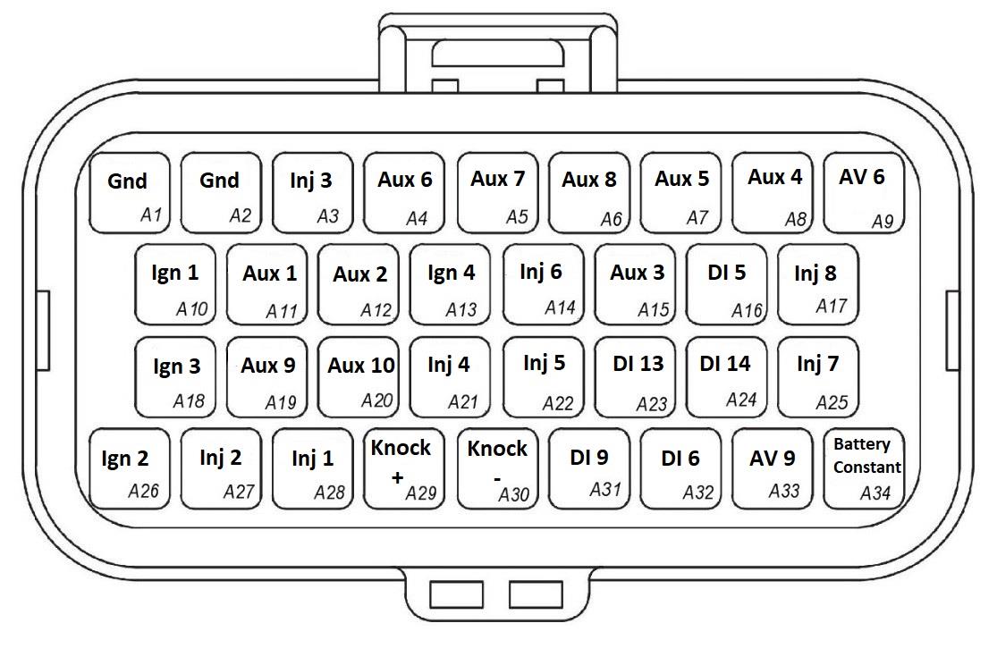
YXZ1000R Connector A — looking into the ECU connector.
| Pin | OEM Pin | Channel Name | Pin | OEM Pin | Channel Name |
|---|---|---|---|---|---|
| A1 | 35 | Power System Ground 1 | A18 | 52 | Ignition Coil Cyl 3 |
| A2 | 36 | Power System Ground 1 | A19 | 53 | Emtron User Output (e.g. DBW +) |
| A3 | 37 | Primary Injector Cyl 3 | A20 | 54 | Emtron User Output (e.g. DBW −) |
| A4 | 38 | Idle Stepper – W2 - A | A21 | 55 | Fuel Pump 1 |
| A5 | 39 | Idle Stepper – W1 - B | A22 | 56 | Radiator Fan Relay 1 |
| A6 | 40 | Idle Stepper – W2 - B | A23 | 57 | Hand Brake Switch |
| A7 | 41 | Idle Stepper – W1 - A | A24 | 58 | Brake Switch 1 |
| A8 | 42 | PVC Solenoid Output (Paddle ONLY) | A25 | 59 | Starter Relay Control |
| A9 | 43 | Emtron User Input | A26 | 60 | Ignition Coil Cyl 2 |
| A10 | 44 | Ignition Coil Cyl 1 | A27 | 61 | Primary Injector Cyl 2 |
| A11 | 45 | YXZ Differential Lock Relay 1 | A28 | 62 | Primary Injector Cyl 1 |
| A12 | 46 | YXZ Differential Lock Relay 2 | A29 | 63 | Emtron Knock 1+ Input |
| A13 | 47 | Seat Belt Pilot Lamp | A30 | 64 | Emtron Knock 1- Input |
| A14 | 48 | User Output 3 - Parking Brake Buzzer | A31 | 65 | Differential Servo Position 3 |
| A15 | 49 | Tacho - (Drive for EPS / Trans) | A32 | 66 | Clutch Switch (Non-paddle ONLY) |
| A16 | 50 | Start/Stop Switch | A33 | 67 | Trans ECU Current Feedback / Emtron User Input |
| A17 | 51 | User Output 2 - Air Induction Relay | A34 | 68 | Battery Constant Voltage |
Connector B: Signal / Power / Communications / Triggers / Knock
(15.0A Max continuous current - wire gauge dependant)
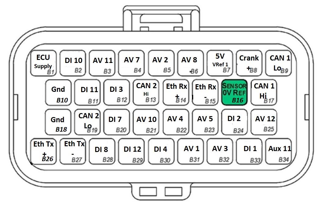
YXZ1000R Connector B — looking into the ECU connector.
| Pin | OEM Pin | Channel Name | Pin | OEM Pin | Channel Name |
|---|---|---|---|---|---|
| B1 | 1 | ECU 14V Supply | B18 | 18 | Control System Ground 2 |
| B2 | 2 | YXZ Differential Switch 12 | B19 | 19 | Emtron CAN 2 Low |
| B3 | 3 | YXZ Differential Lock Rotary Switch 1 | B20 | 20 | YXZ Differential Servo Position 1 |
| B4 | 4 | Engine Temperature | B21 | 21 | Neutral Switch |
| B5 | 5 | Manifold Pressure – Bank 1 (Cyl 1) | B22 | 22 | Gear Position Sensor (Non-paddle) |
| B6 | 6 | Inlet Air Temp | B23 | 23 | Lean Angle Sensor |
| B7 | 7 | Sensor 5V Power Source | B24 | 24 | Speed Sensor |
| B8 | 8 | Crank Position Sensor | B25 | 25 | YXZ Differential Lock Rotary Switch 2 |
| B9 | 9 | CAN Bus Low (OEM) | B26 | 26 | Emtron Ethernet Tx + |
| B10 | 10 | Control System Ground 1 | B27 | 27 | Emtron Ethernet Tx − |
| B11 | 11 | YXZ Differential Switch 1 | B28 | 28 | YXZ Differential Servo Position 2 |
| B12 | 12 | Battery Voltage Monitor | B29 | 29 | YXZ Seat Belt Switch |
| B13 | 13 | Emtron CAN 2 High | B30 | 30 | User DI (Ethanol/Switch/Analog) |
| B14 | 14 | Emtron Ethernet Rx + | B31 | 31 | Throttle Position 1 |
| B15 | 15 | Emtron Ethernet Rx − | B32 | 32 | Manifold Pressure |
| B16 | 16 | Sensor System Ground | B33 | 33 | Oil Pressure Switch |
| B17 | 17 | CAN Bus High (OEM) | B34 | 34 | Fan2 Relay (Paddle) |
7.1 Important Notes
Analog Sensor 0V Reference (Pin B16) — Connect directly to the 0V (Ground) pin on any low current analog sensor. DO NOT connect ECU pin B16 directly to the Engine Block or ECU Ground. DO NOT connect frequency-based sensors to these pins; the sensor 0V pin should be connected to the ECU ground.
WarningWARNING Replacing the MAP Sensor for Boosted applications. The MAP sensor located on Cylinder 1 is used to synchronise the engine — do not replace this MAP sensor with an alternative item, as replacement will result in loss of 720 sync and engine start. When shifting to a boosted application, the correct MAP sensor to replace is located on Cylinder 2 (Input Channel AV3 – Manifold Pressure).
8.0 Software
Emtron’s comprehensive Emtune tuning software is used to connect to the ECU (Windows 7-10, free licence, 0.5GB RAM, Ethernet IPV4). Tuning and data analysis, PC and ECU data logging, live pause and playback, advanced tuning functions, diagnostics and oscilloscope display.
9.0 Ordering Information
| Product | Part Number |
|---|---|
| Emtron YXZ ECU | 1609-252426 |
| Emtron Ethernet Tuning Cable (1.5m) | 553-15 |
| Emtron Communications Cable, Superseal to Emtron Connector 200mm | 533-02 |
Appendix A – YXZ1000R Series Ethernet Wiring
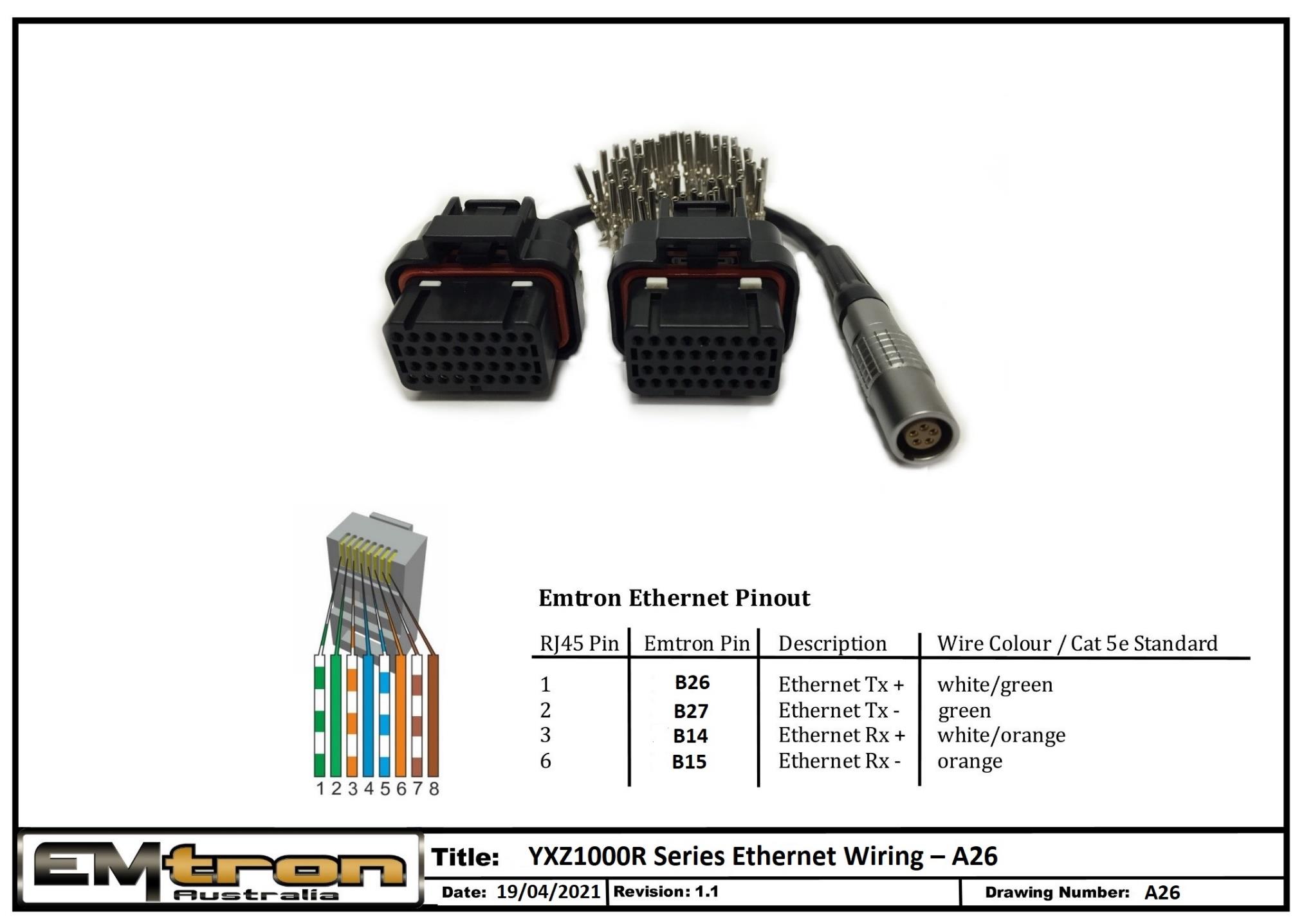
YXZ1000R Series Ethernet wiring / tuning cable pinout (drawing A26).