Firmware Release Notes
Emtron ECU firmware is packaged with Emtune via EmUpdater.
After an ECU firmware upgrade, please read ALL the firmware update information from the previously installed version up to and including the current version. Connect to Emtune and apply any changes to ensure the ECU is correctly configured to run the latest firmware.
When active, the internal ECU logging will require reactivation after an ECU firmware upgrade.
When performing a firmware upgrade on a plug-in ECU, the ignition coils be should be unplugged!
Loading release notes…
V2.20.22
18/11/2025
- Added data logging to Shadow 8.
- Added Next Upshift Lockout Time to Gearshift Control.
- Added channels to axis selection.
- Added Gear Detection Tracking input selection to Gear Management so 2 sources can be used at once again.
- Added ORFC anti lag and rev match lockouts.
- Increase idle initial position clamp to 150g/s
- Traction control driver demand clamp status added
- Traction torque final clamped to 5000nm.
- Added ORFC Cruise control torque lockout.
- Compression Ratio correction applied to TMF Torque & Driver Demand Torque.
- Shadow DI min frequency now 2Hz (from 12Hz).
- Added Driver Demand Peak Manifold Pressure table.
Table must be setup after update for Driver Demand Torque to work. - Added Traction exit delay.
- Added EMAP Estimate baro compensation.
- R35 TCM can now be flashed with Emtron ECU in place.
- Added TM16 Torque Gearshift Control mode.
- Added TM16 CAN data set.
Improvements/Fixes
- Fixed Fuel Rate (and Fuel Used) calculation (broken in 2.20.0).
- Updated Evo X CAN data.
- Fixed Ambient Temp Cal.
- Fixed fuel pump speed 2 PWM after power cycle.
- Fixed Cal slot table Y axis.
- Added max clamp of 10 to cruise up down counter.
- Fixed stepper motor control on Shadow 8.
- Cleaned up gear detection runtimes.
- Traction slip mode rapid on/off during lockouts fixed.
- Fixed Shadow single zone arming thresholds.
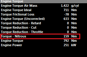
- NOS torque applied to uncorrected torque.
- NOS Status updated for clarity.
- Antilag DBW override on TA Table mode 7 fixed.
- Cruise paused-pedal error fixed.
- Shadow ethanol sensor on DI1-8.
- ORFC lockouts fixed.
- Fixed cornering speed calculation.
- Fixed DI High Range input ignoring arming threshold table.
- Fixed logging of User Switches and User Functions 11-15.
V2.20.0
20/12/2024
- Added support for Shadow 8 ECU.
- Simplified Air Mass Model setup and added “Emtron Air Mass Model”.
- Added Banked Air Mass mode with independent bank VE tables.
Not Implemented for Staged Injection. - Timers now have additional Reset/Stop Functionality with User Channels 1- 15 added.
- Altitude Calculation function added.
- Tyre Pressure input channels added.
- 5x User Switch inputs added.
- Added Reverse Switch Input.
- Torque Limit via CAN Added.
- Special HKS VCam trigger mode added (36-2 + 3).
- Added User definable TMF filter mode & table.
- Added a new CAN Driver Demand Torque Modifier Table.
- CAN Bus Reported Torque Modifier tables now universal.
- Added Ideal Torque Compression Ratio Correction Table.
- Added Advanced CAN Rx Data Set.
- Added Cruise Set/Resume Counter for general purpose use.
- Added Cal Slot Tachometer indicator function.
- Added SENT protocol support
- Available on Shadow 8 DI6 only.
- Not available on current KV/SL hardware.
- Currently supports GM Throttle bodies.
Improvements/Fixes
- Yamaha YXZ Build Updates including adding Crank Index Input Filtering.
- Improvements to Staged GDI control.
- Slip Target Table 1 now 22x11 16-bit Table (from 8-bit).
- Slip Target Table 2 now 16x10 16-bit Table(from 8-bit).
- Added “Always On” option to User Torque Limits.
- Torque limit calibration function added.
- Added Oil Temperature to BRZ/GT86 and Subaru MY15+ CAN bus set.
- Added Cruise speed to Subaru MY15+ OEM CAN.
- Added the correct Fuel Mass/cycle calculation for Subaru CAN Bus (Eco Gauge).
- New Override settings for the Subaru CAN Bus.
- Fixed Evo X AC Switch CAN message.
- Added numerous channels to table axis control.
- Closed Loop Lambda now holds during Gear Shift cut instead of turning off.
- DWB Integral Gain ignoring dead-band - FIXED
- Clutch Pressure labeled as Bar but should be kPa - FIXED
- Fuel Level 2 & Fuel Level 1 error when both in use - FIXED
- User Channels 13/14/15 not storing channel 4 properly - FIXED
- User Idle target offset table doesn’t use Y axis - FIXED
- VVT Target table interpolation error when crossing 0 - FIXED
- VVT Exhaust Target Table 2 negative numbers output as positive - FIXED
- Non functional Ignition Mode 6 “Wasted Spark + Trailing Spark(wasted)” - FIXED
- Cannot Invert DI Status Inputs when using keypad Button - FIXED
- Momentary Switch Inputs not working when using keypad button - FIXED
- Cruise Build not working when Y61 2017+ Build added - FIXED (The Y61 Build will need to be uninstalled then reinstalled to make Cruise Control Active)
- Changed Engine Torque CAN Modifier table to 16-bit. Now have 0.1Nm of res instead of 5Nm.
This may require all OEM CAN Bus data to be validated. - Charge Temperature Comp table reduced to 12x11.
This may require manual validation if used. - Engine Temp Comp Table 2 reduced to 12x11.
This may require manual validation if used. - TMF Correction Table reduced to 12x11.
This may require manual validation if used. - Fuel Temperature Comp Table removed.
This may require migration to a User Fuel Comp table if used. - Boost Clamp table now 16-bit (from 8-bit).
This may require manual validation.
V2.19.0
10/7/2023
- TMF Airflow model revisions.
TMF v1.0 no longer available -Calibration will have to be upgraded to current TMF - TMF Filter co-efficient added for a smoother response
- TMF uncorrected outflow correction table added.
- Torque Limit Torque Strategy features added – User control, CAN receive, Launch Control, Traction Control support.
- Torque Limit User control feature
- Revisions to Torque based Traction Control Function.
Uses new torque strategy - Calibration will require validation - Launch Control Torque Strategy Select tables added for static and moving
- Downshift Rev Match
- Autoshift for Drag Racing
- Channels added to Channel Selector
- Twin Cylinder VE support
- Turbosmart E-Gate Blackbox supported
- LX570 Lexus Application Build support
- Nissan 370Z Application Build support
- G-Speed latching feature for rolling start calculations
- Added generic wheel speed inputs with filtering tables and assignable channels.
Wheel Speed Input setup has changed and will require reconfiguration
Unfiltered Drive Speed
Filtered Drive Speed
- Added extra User Functions, 15 total, up from 10
- Race Timer improved resolution (1ms)
- K24Z7 Trigger support
- 6B31 Trigger support
- MR16 Trigger support
- Lynkco Trigger Support
- Dodge 420A Trigger support
Improvements/Fixes
Ethernet Configuration Tool
Firmware Update Wizard
Theme Update
Quick Help “H” updated
User Configurable menu system
User Functions/Systems - Labeling
User Functions now use Condition Statements for improved logic readability - Configuration will require updating for continued operation
Preset sensor calibrations - added
ECU Logging calculates max time
Tables added and re-structured/Menus Updated - Calibration will require update if the following tables are in use
- Main VE3 is no longer available
- Ignition Table 3 is no longer available
- Charge Temperature Comp Table 2 no longer available
Cal Slot Control updated
Air Mass final channel reading 0 at high rpm – FIXED
Minimum effective PW not storing when below 0.2 after power cycle – FIXED
Secondary Injector timing not following any channels in a table – FIXED
Gear cut Ignition retard not updating during shift – FIXED
Expansion Ratio VE Calculation below 0% causes high VE - FIXED
TMF calculation reading dropout when outflow still valid – FIXED
2 Stroke Torque Calculation - FIXED
Lambda 2 Integral Gain - FIXED
V2.18.0
1/8/2020
- Throttle Mass Flow calculation upgrade to Version 1.1. For tuning consistency the user can select the previous V1.0 or transition to the new V1.1. See Engine Functions -> Throttle Body Model -> Throttle Mass Flow Setup.
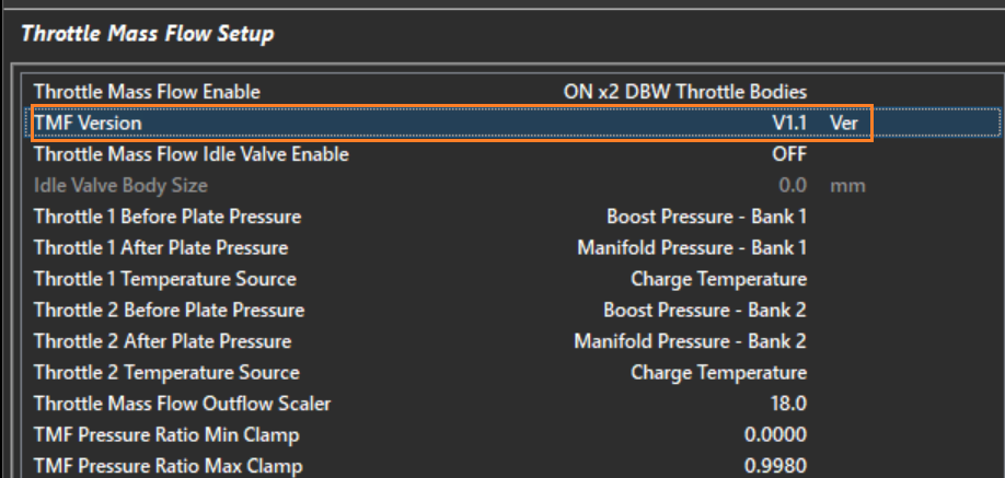
TMF V1.1 improvements available on ECU Firmware 2.18.0 or later:
- Converted TMF Mass Flow (g/s) runtime to 2dp for improved resolution
- Fuel Table 3 has be reassigned to a “TMF Correction Table”.With TMF enabled, this table is active all the time and allows the Throttle Mass Flow to be corrected when required. See Tuning View -> Fuel Menu.
WARNING. Please check this table after a firmware update and initialise to 0.00% if TMF mode enabled
- Pressure Ratio < 0.528 is now unclamped and user defined. Initialise “TMF Pressure Ratio Min Clamp" to 0.5283.
- If the Pressure Ratio Min Clamp is set < 0.528 the fueling will need adjustment either by using the Throttle Area table or TMF Correction Table.
- Pressure Ratio Maximum Clamp is now user defined. Initialise “TMF Pressure Ratio Max Clamp" to 0.9980.
- Initialise “Throttle Mass Flow Outflow Scaler” to 18.0.
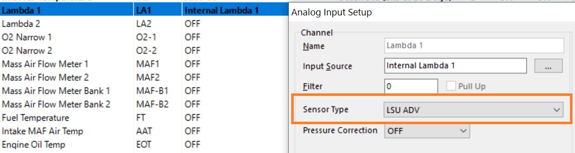
- Lambda Sensor ADV 4.9 now supported.
Manifold Pressure Sensor Calibration added
Flame function added
EVO X full OEM CAN Bus Integration (Application Build)
CAN-Am full OEM CAN Bus Integration (Application Build)
D-Gain added to Closed Loop Lambda Control.
Temperature channel scaling. Can now select Ohms or Voltage as a calibration option.
Support added for Mid-Lock VVT. Supports Inlet target range of +70 to -20 Degs and Exhaust range of -70 to +20 Degs
Renamed “MAP Modelled’ functions and runtimes to “AIr Mass Modelled”
Added New Fuel Model (TMF + Speed Density (Blend) to Fuel Model setting position 4. The old position 4 (Mass Air Flow Sensor(MAF) + AirMass Modelled (Blend)) has been moved to Option 9
VW Golf Mk 4 OEM CAN Bus supported added
Engine Decoding Added
- Lamborghini LP700-4 V12 trigger
- Jeep Cherokee V8 4.7L
- GT86 2017+ with Mid-Lock VVT
- Changan 4D20
- Hemi 6.4L
- EVO 12-teeth decoding decoding option
- Renault F4A
Fixes/Improvements
- Fixed “Gear Cut End Source” when selected to Clutch Switch
- NOS fixes to Entry and Exit Delays
- Vanos clamped increased to +/-90% during engine cranking
- Gear voltage fault mode
V2.17.0
20/9/2019
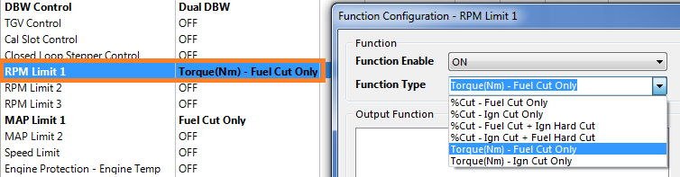
- Engine Speed Limit 1 now has the option to be Torque controlled. The ECU will target a user feed-forward Torque (Torque Target), then apply closed loop PID control to reach the Target RPM, finally converting Torque into a %Engine Fuel or Ignition Cut. See Config View -> Engine Functions -> RPM Limit 1
- Ground Speed Limit 1 is now Torque based, giving significant improvement over the previous open loop %Cut system. The ECU will target a user feed-forward Torque(Torque Target), then apply closed loop PID control to reach the Target Ground Speed, finally converting Torque into a %Engine Fuel or Ignition Cut.
NOTE: Please check and initialise the function after the firmware update
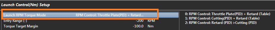
- Torque based Launch Control. Three new Torque based launch strategies have been added giving significant improvement to engine speed control by precisly controlling the engines torque during the static and moving phases of Launch Control. ECU will target a user feed-forward Torque (Torque Target), then apply closed loop PID control to reach the Target Launch RPM, finally achieving the Torque Target by Throttle Plate control, or/and Ignition Retard or/and %Engine Cutting. The following modes are available, for more information please refer to the help.
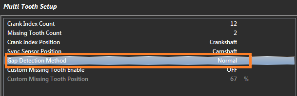
- Multi-tooth Trigger mode as a new Gap Detection option for engines that exhibit rapid acceleration/deceleration (engines with light flywheels and/or big camshafts)
- Can-Am Application Build including full OEM CAN Integration
- Added Nitrous Exit Delay table. This keeps the Ignition Retard and Fuel active after the NOS solenoid has switched OFF
- Cruise Control Application Build. This is an advanced feature with the ECU managing engine torque (Nm) by calculating the correct throttle area for the target vehicle speed. Any speed error is then corrected using a PID controller. This will require a dealer to register the ECU serial number to allow the feature to become active and to ensure all the sensors are correctly configured.
NOTE: Please read the “Cruise Control Application Build - Emtron.pdf” document available for download from the Emtron website.
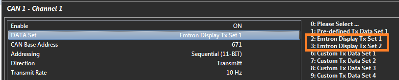
- New CAN Bus predefined Datasets available for the new Emtron Display
Engine Decoding Added
- Jeep 4.7L
- Jeep 4.0L
- Ford Coswroth
- Mercedes 120
- Viper Gen 1
- Mx5
Fixes/Improvements
- All Torque runtimes converted to 1 Decimal Point. NOTE: Please check and initialise any Table/Function using this runtime after the firmware update
- Gearshift Mechanical 1st to Neutral inhibits added
- Emtron CAN keypad general improvements
- Cruise Control added to Y61 Application Build
- Distance Reset switch fixed
- Output shaft input channel pulled control fixed
- Gear Voltage 1 Input fault value not loading correctly in a fault condition has been fixed.
V2.15.0
8/3/2019
- Gearshift Function. Added a new Gearshift Setup menu in the Tuning view. This contains a new “Gear Position Order” setting for the user the select the correct gear sequence. This settings allows the ECU to determine the correct shift and half-shift sequence. Also two new Half-Shift control modes have been added for selecting Neutral when its placed half-way between 2 gears. These are:
Reverse -> Neutral half-shift
1st -> Reverse half-shift
NOTE: Please check and initialise the settings in this new menu after the firmware update
- GDI HPI5 “Closed” pump control added
- Sensor Ratiometric Correction added to selected Input Channels. This allows the ECU to correct a sensors output based on its supply voltage. The Manifold Pressure input channel example is shown below.
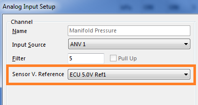
Click this link to download more information: Ratiometric Correction Download
NOTE: Please check and initialise this new setting after the firmware update. The following Input Channels should be checked
- Manifold Pressure
- Manifold Pressure - Bank 1
- Manifold Pressure - Bank 2
- Boost Pressure
- Boost Pressure - Bank 1
- Boost Pressure - Bank 2
- Engine Oil Pressure
- Fuel Pressure 1
- Fuel Pressure 2
- Exhaust Manifold Pressure 1
- Exhaust Manifold Pressure 2
- Crankcase Pressure
- Added 29 BIT CAN address for Single and Sequential modes (Transmit and Receive)
- Added CAN Channels 5 and 6 to CAN 2 Node.
- Emtron Keypad CAN interface firmware.
Engine Decoding Added
- Chrysler Jeep 3.6L
- Honda L15B VVT
Fixes/Improvements
- Fixed CAN Transmit issue on CAN 2 Channels 3 and 4.
V2.14.0
20/12/2018
- ECU Application Builds are now available. These are primarily OEM integration builds and can be installed into any ECU. Builds can be installed using the File -> Build Management menu when available. Individual Application Build documentation will be available from the website. Currently the follow Build options are available:
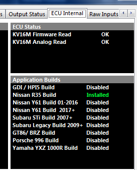
- Completed Nissan Patrol Y61 Application Build. This build allows unique application specific firmware to be installed into the ECU. The Y61 build includes the following:
- Full CAN Bus OEM integration for both Automatic and Manual Transmissions.
- Y61 Gearshift control for automatic transmissions. This controls and monitors the Engine Torque during the gearshift.
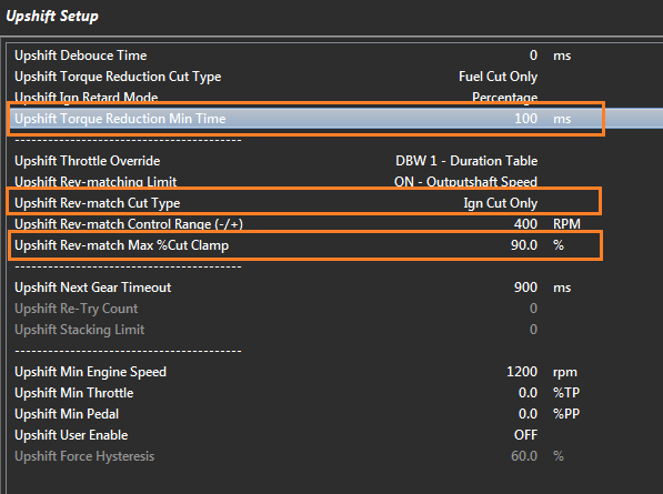
- Gearshift function improvements
Gear position tracking feature added
Rev-matching corrected
Improvements made to the lockout features
Added following new settings:
- “Upshift Torque Reduction Min Time”
- Upshift Rev-match Max %Cut
- Upshift Rev-match Cut Type
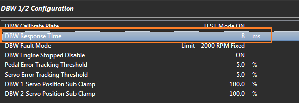
New DBW PID control strategies.
The DBW PID control has been significantly changed which may require the PID data to be re-tuned.
Predefined DBW calibration files are now available from the File -> Import Module File
a) The most significant change, is the PID control now includes an adjustable System Response time
(The response time is the time from a commanded input change to the output changing)
The PID control will now adjust its behavior based on this response time and should result in a more simplistic approach to the PID tuning. (Use the File -> Import Module File menu to view the different examples)
NOTE: The “DBW Response Time” will need to be initialised after the firmware update. Recommended starting value is 8ms.
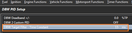
b) The DBW Target Filter has been converted into a digital Low Pass Filter with the Time Constant adjustable in units on ms.
This works well at "Softening" the edge during sharp transitions.
NOTE: The “DBW Target Filer -Time Constant” will need to be initialised after the firmware update.
Recommended starting value is 15ms
Closed Loop Stepper Motor control added. Available for both Bipolar and Unipolar devices.
Engine Protection Function improvements.
NOTE: Some settings may have changed within the Engine Protection function.
PLEASE check these settings after the firmware update
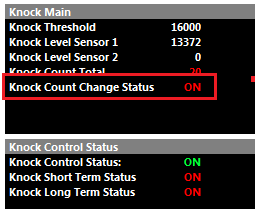
- Added new Knock runtime Status “Knock Count Change Status”. When the Knock Counter increments the Status turns to ON indicating there has been a Knock event. The Status will switch to OFF once all Knock events have stopped(counter stops incrementing). This Status is available in the User Channels and can be setup to control an external Knock warning system.
- Cruise Control update for Nissan R35 Plugin ECU
Engine Decoding Options added
- Chrysler Jeep 3.6L
- Lamborghini Gallardo V10
- Nissan VQ40
- Hemi 6.1L
Fixes/Improvements
- Long term and Short term knock Status only updating from Cylinder 1 Knock event - Fixed
- Pedal Position Demand does not work in the ECU logger - Fixed
- Launch Retard allows ignition to go below the Min Ignition Retard clamp - Fixed
- ECU Logged Channel Barometric Pressure had wrong offset x10 - Fixed
- Timer 3 when multiple AND conditions used - Fixed
- Race Timer when Transbrake = ON - Fixed
V2.12.0
16/4/2018
Toyota GT86/ Subaru BRZ Plugin ECU firmware ready for initial release.
Gearshift protection functions added
- Neutral -> 1st Lockouts
- 1st -> Neutral Lockouts
Cam Switch ON -> OFF hold timer allowing the output to remain ON during a gearshift.
Ford Coyote Quad VCT Trigger decoding added.
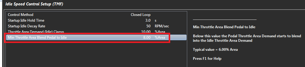
TMF Idle Speed Control - Idle to Pedal Crossover point is now adjustable.
DTC Codes added for:
- Barometric Pressure
- Fuel Tank 2 Level
- MAF Bank 1 Sensor
- MAF Bank 2 Sensor
Multiple ELC CAN Bus Configuration change: The ECU CAN Bus configuration on Multiple ELC devices can now be completed using only one ECU CAN channel. See Emtron ELC - User Manual 1.1.
Fixes/Improvements
Improvements to GDI Pump control strategies and PID algorithm.
Gearshift Throttle Blip Fix
Momentary switching of Auxiliary 9-12 drive at ECU power up has been fixed
Engine Temperature reading on ANV 9-12 Inputs at ECU power up has been fixed
Improvement to CPU %Load
V2.11.0 26/2/2018
Nissan R35 Plugin ECU firmware ready for initial release.
KV16M firmware ready for initial release.
NOTE: The Input Source selection has had a small shuffle around from the CAN Voltage 1 option downwards. Please re-check your settings after the firmware update.
- DBW Throttle Mass Flow (TMF) Idle Control added. (Idle Target in g/s). The ECU uses pressure before and after the butterfly to calculate
the correct throttle area for a given flow target (g/s)
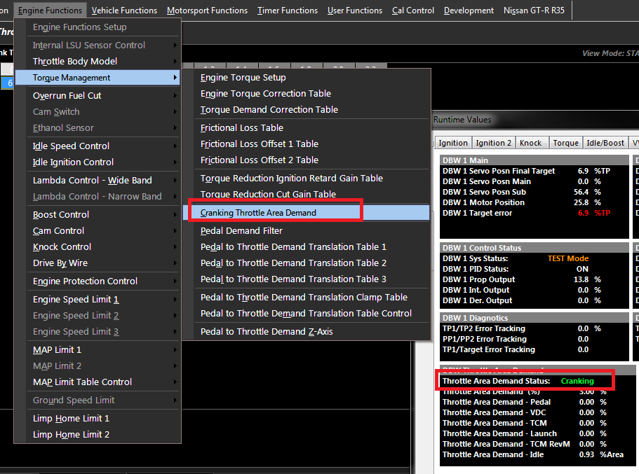
- DBW Cranking Throttle Area Demand added. This allows the Throttle Area to be controlled during cranking. The
“Throttle Area Demand Status” indicates this state as shown below.
NOTE: Please check and initialise this setting after the firmware update. Use the sample file for base settings.
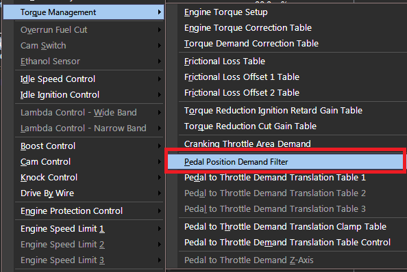
- Pedal Position Demand Filter.
The Pedal Position Sensor 1 has an Exponential Smoothing filter applied using the coefficients set in this table. This generates a new output called “Pedal Position Demand” and this filtered signal
can be used to span the Pedal to Throttle Demand Translation tables. For more Help information press the “H” key when the table is selected/opened inside Emtune.
NOTE: Please check and initialise this setting after the firmware update. Use the sample file for base settings.
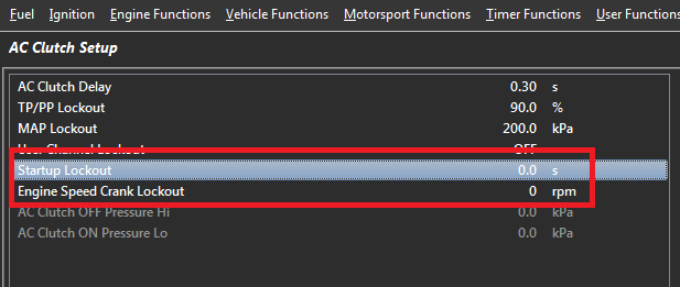
- AC Clutch Startup and RPM Lockouts added. NOTE: These will need to be initialized and set correctly
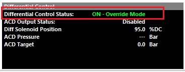
- Differential Control Override option added.
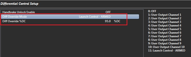
The Function status will update when this mode is active:
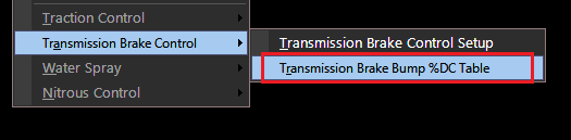
- Transmission Brake Bump PWM mode added. When the frequency of the Trans-brake solenoid is set to greater than 0Hz, the Bump function will modulate the solenoid at the duty cycle entered into the “transmission Brake Bump %DC Table”
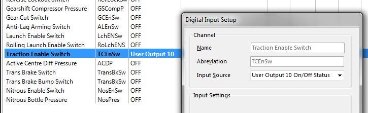
- User Outputs On/Off Status can be selected as the Source Input for a digital Input Switch. Below picture shows Use Output 10 as the source Inputs for the Traction Enable Switch. When User 10 Output is ON, the Traction Switch will be ON
Added Fuel Tank 2 Level, Input Channel.
29-Bit CAN Bus options added.
Fixes/Improvements
Charge Temperature Offset Table
Lambda Closed Loop lockout when ELC in fault condition
Gear Cut Function - Next Gear Stable End Cut mode.
V2.9.25
19/9/2017
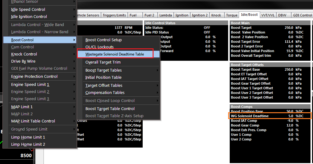
- Added Boost Control Solenoid Deadtime Table to help linearise the boost solenoid(s) response. A “Boost Solenoid Deadtime” runtime has been added converting ms into %DC.
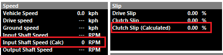
- Two new calculated runtime added:
- Input Shaft Speed (Calc). This uses Output Shaft Speed and Gear Ratio to reverse calculate the Input Shaft Speed. Used on applications when there in no Input Shaft Speed or there is insufficient resolution.
- Clutch Slip (Calculated). This is Clutch Slip based on Engine Speed and Input Shaft Speed (Calc)
 '
'
- Nitrous Function added - Up to 4 Stages.
Key features:
- Comprehensive list of Lockout parameters
- PWM Option available on Stages 1 and 2
- Can individually set the Fuel Flow requirement for each Stage. All scaling is metric with units of g/s.
NOTE: g/s = lb/hr x 0.12599
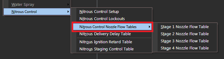
Delivery Delay table defines the time for the Nitrous the travel from the solenoid to Nozzle when the solenoid is first turned ON. This includes the solenoid deadtime and transport delay.
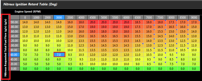
Ignition Retard is done using a 3D table and spanning one axis from Total Nitrous Flow .. the more flow the more retard can be applied.
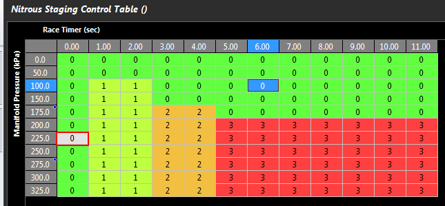
- Nitrous Staging is control using a 3D Table. The stage number can be entered directly into the table:
0 = OFF
1 = Stage 1 ON
2 = Stage 2 ON
3 = Stage 3 ON
4 = Stage 4 ON
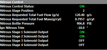
- Comprehensive list of Nitrous runtimes under the Runtime menu -> Motorsport 1 Tab
- Nitrous Torque data has been added. For Gain control see the menu: Engine Functions -> Torque Management -> Engine Torque Setup.
“Race Timer Reset” control added.
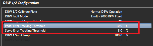
Pedal and DBW Servo Position Error Tracking Threshold is now adjustable.
- Added more options to the “Reset Fuel Used " and “Reset Distance” settings.
NOTE: Please check after the firmware update.
Dual Closed Loop Lambda can have the Gain table spanned using the runtime “Lambda 1/2 Target Error - Shared”. This means both Lambda 1 Error and Lambda 2 Error will be used for the interpolation on each channel respectively.
Trigger Decoding added:
- Toyota 2UZFE VVTi
- BMW S50 Euro
- BWM S55
- Ford Duratec 2.3L
- New Input Channels
- Clutch Pressure
- Exhaust Pressure 2 (NOTE: If enabled, please recheck “Exhaust Pressure 1” calibration after the firmware update)
- Exhaust Pressure Average (when Exhaust Pressure 1 and 2 are enabled and NOT in fault an average value will be calculated)
- Several functionality changes resulting from the new Exhaust Pressure 2 Channel:
- Fuel Model: Expansion Ratio. Option 3 has been added. “ON - EMAP Sensor 1/2 AVG "
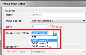
- Internal Lambda Pressure Correction. More options have been added so Bank Lambda Pressure correction can be setup. The Options are: OFF, Exh Press 1, Exh Press 2, Exh Press Avg
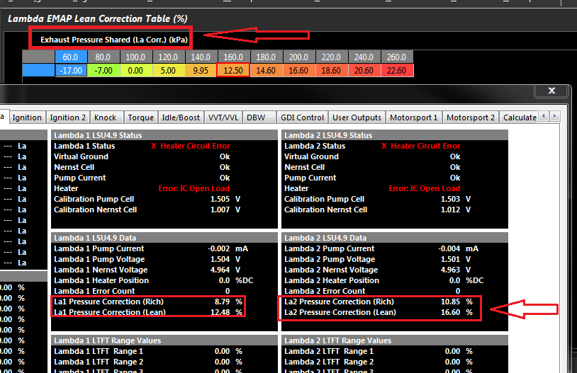
Also the La Pressure Correction Rich/Lean Tables should be spanned using the new runtime " Exhaust Pressure Shared”. This will allow the ECU to internally manage the axis parameter (Exh Press 1 or 2) based
on the user settings. There are new Pressure Correction runtimes for each channel as shown below.
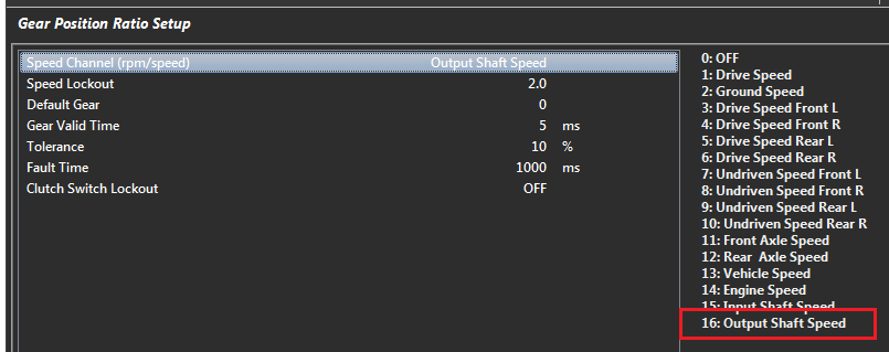
The RPM/Speed calculation used for Gear Position now has OutputShaft as a speed option (ie RPM/Output Shaft)
Wastegate Position 1 and 2 added with the option of % or cm for units. See Turbo Dynamics Tab on the Config View.
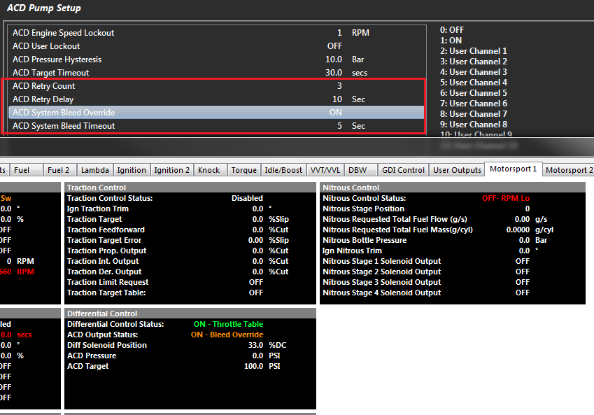
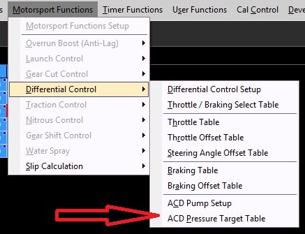
ACD Diff Control functionality added:
- Pump Bleed Override
- Retry system allowing the ECU to restart the Pump in the event of a Timeout Condition (ie Pump could not reach Target Pressure)
Additions options added to the Manifold Pressure Estimate calculation. See the Config View -> Channels -> Manifold Pressure Estimate menu.
New Input Channel: “Boost Pressure” . Placed before the Throttle Plate to measure boost pressure which is used in Throttle Mass Flow calculations.
Traction Control has a new “Traction Control State” runtime that indicates when TC is working (shows OFF or ON) . So for example a User Channel could be configured to switch an output when the status shows ON. (Traction Control Light)

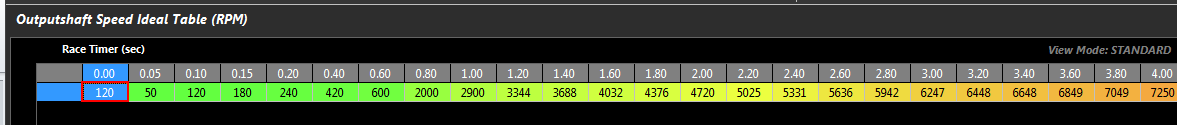
- New Runtime: Outputshaft Speed “Ideal” . See Vehicle Functions -> Vehicle Dynamics menu.
It is normally used to drag applications and represents the “ideal” or “target” Outputshaft Speed for a run. The ECU can then generated a %Output Slip based on this value and the actual Outputshaft speed. This %Output Slip can then be applied to the Traction Control system.
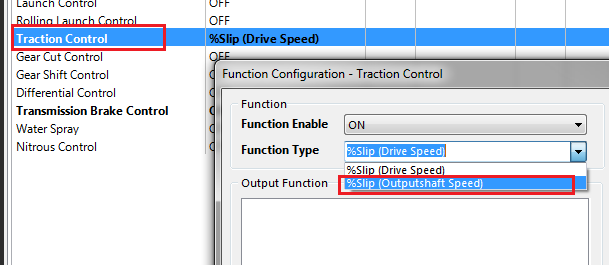
New Runtime: Outputshaft Slip. This is the Slip between the Outputshaft Speed “Ideal” and the selected Source channel. See Vehicle Functions -> Vehicle Dynamics menu. The Outputshaft Slip can be selected to within the Traction Control Function
New Traction Control mode : “%Slip (Outputshaft Speed)
New Runtime: Outputshaft Speed Calculated. This is reverse calculated by using Wheel Speed (kph) and Final Drive ratio to get Outputshaft Speed Calculated. Useful when the actual Outputshaft Speed is unavailable from the the transmission. See Vehicle Functions -> Vehicle Dynamics menu ->Outputshaft Speed Calculated menu.
New Runtime: Inputshaft Speed Calculated. This is reverse calculated using OutputShaft Speed Source and Gear Ratio. Useful when the actual Inputshaft Speed is unavailable from the the transmission.
See Vehicle Functions -> Vehicle Dynamics menu ->Inputshaft Speed Calculated menu.
New Runtime: Clutch Slip 2. Now have x2 Clutch Slip channels with independent source channels. See Vehicle Functions -> Vehicle Dynamics menu ->Clutch Slip menu.
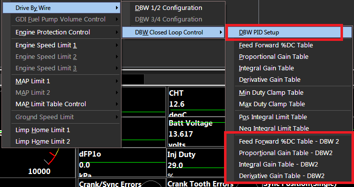
Custom DBW 2 PID settings. These can be enabled from the DBW PID Setup menu.
- Gearshift Functions Changes
- The Gear Detection Voltage Channel will now show the value -10 when tolerance mode is used AND the Gear voltage is outside the tolerance. This will normally happen during an Upshift or Downshift event. It can also indicate a miss-shift issue when the gearbox is stuck between two gears.
- When Gear position is selected to use “Gear Detection Voltage” as the source, the “Upshift/Downshift Next Gear Timeout” setting(s) are used to determine when the “Gear Detection Voltage” should be updated to the Gear position.
Example: During a 2rd to 3rd shift the Gear Detection Voltage channel will show 2 > -10 > 3. Corresponding the Gear position will start showing 2, followed by -10, then wait until a valid gear position is available; In this case it will be 3, so the user will see the Gear position 2 -> 3. In the event a valid Gear position is not seen when the Timeout period ends, the Gear channel will be update to a value of -10 indicating a fault.
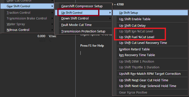
- Upshift Cut tables have been separated out into Ignition and Fuel allowing more flexibility around cut strategies.
- Rev-Match Calculation updated during the entire Up/Downshift event.
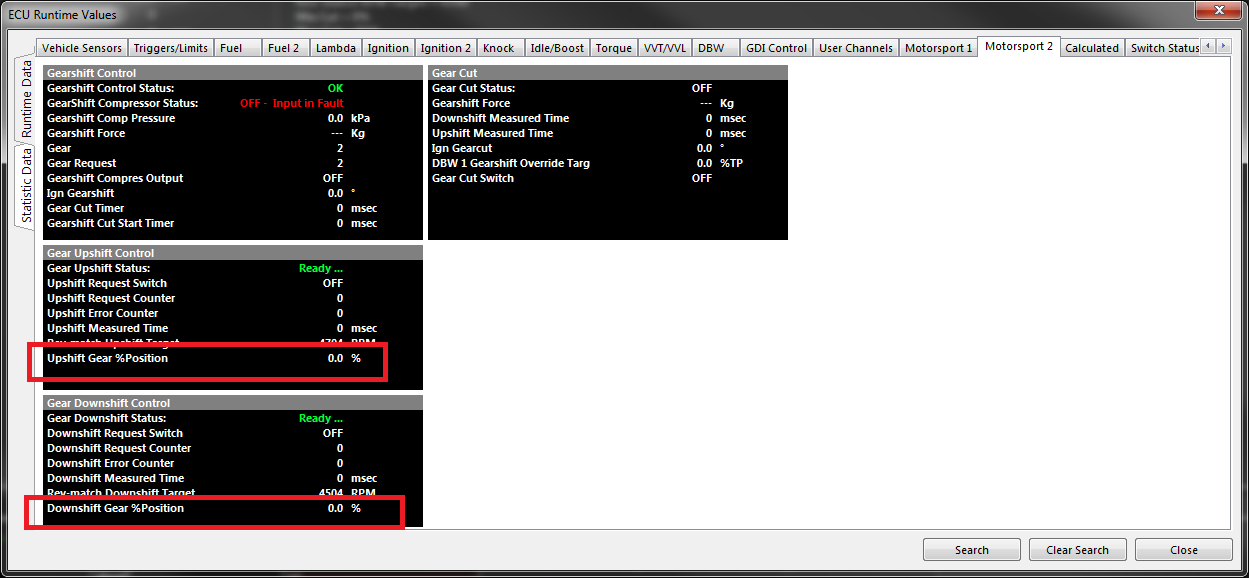
- Upshift and Downshift Gear %Position runtime added. During a Gearshift event the ECU calculates the position of the Gear from 0 to 100%. This get calculated using the Gear Voltage Channel.
Example: Upshift from 2nd to 3rd. 2nd = 2.45V, 3rd = 3.15V. During an Upshift event the ECU reads the Gear voltage at 2.88V.
Upshift Gear %Position = 2.88 - 2.45/ (3.15 - 2.45) = 61.4%
This information can be used for advanced Gearshift Control Strategies.
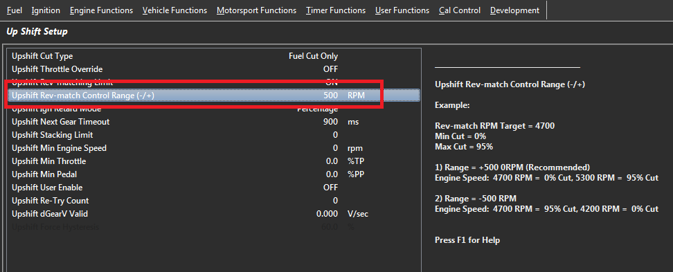
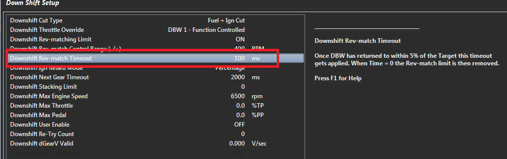
- “Rev-match Control Range” settings added for both Upshift and Downshift.
- Downshift Rev-match Timeout setting added
Fixes/Improvements
- Pedal Translation Table Z-Axis Control
- Traction Control Limit Type: “Fuel Cut + Ign Cut” . NOTE: Please check the “Traction Limit Type” and “Traction Cut Pattern” settings after the firmware update.
- Improvements to KV series Rev 1 runtime availability.
- Clutch Slip menu misalignment . Please recheck “Clutch Slip Calculation Filter” setting after the update.
V2.9.0 30/6/2017
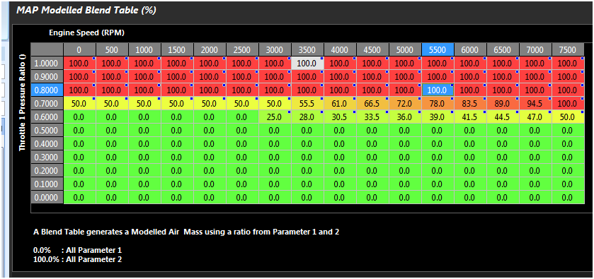
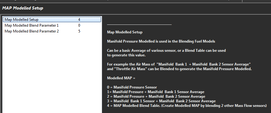
- MAP Modelled, MAP Modelled Bank 1, MAP Modelled Bank 2 are now user controlled calculated runtimes. A 3D table can be used to blend 2 runtimes generating a final Modelled g/cyl and Modelled MAP value.
For example:
- Common Plenum. The Manifold Air Mass and TMF (Throttle Mass Flow) can be blended to generate a “Manifold Pressure Modelled” and “MAP Modelled Air Mass”
Parameter 1 = Throttle Mass Flow 1
Parameter 2 = Manifold Air Pressure
As TMF is a more effective way to manage the engine as high pressure ratio across the blade, this example shows the engine only running on TMF when the pressure ratio is less than 0.6, then transitioning to MAP as this sensor becomes more accurate.
NOTE. Pressure ratio moves towards 1.000 as the throttle moves towards the open position. Pressure Ratio = Pressure After Blade/ Pressure Before Blade
See Config view -> Channels -> Calculated Runtimes
- Two new Fuel Models have been added allowing the MAP Modelled runtime to be used. These are:
- Dual - MAP Modelled Bank1 + Bank2. Individual Bank Fuel control using MAP Modelled.
- Speed Density (MAP Modelled). Default Speed Density calculation, but using MAP Modelled. For example MAP and TMF can be combined (blended) to form MAP Modelled to run the engine.
*NOTE: - If MAP Modelling is used in the Fuel Model, MAP Modelled should be used to span the Fuel and Ignition tables for consistency reasons.
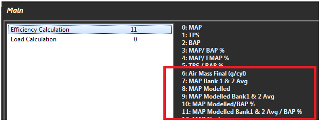
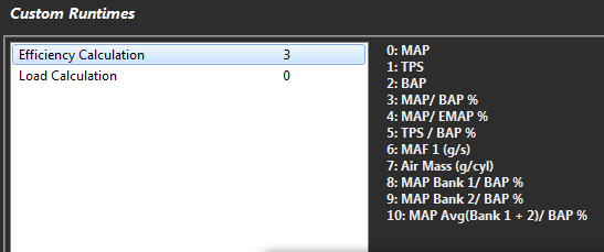
- Options have been added to the Efficient and Load runtime options to account for the new MAP Modelled runtime.
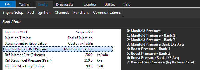
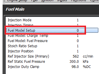
- “Injector Nozzle Ref Pressure” setting has added to Fuel Main setup menu. This is used by the Fuel Pressure correction allowing the ECU to accurately determine Injector Nozzle Pressure.
NOTE: Please check after the firmware update.
- DBW Position feedback and Throttle Position inputs have been separated. The DBW Position feedback is now called “DBW Servo Position Main/Sub”.
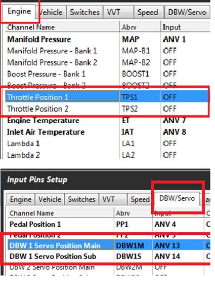
NOTE: If DBW is enabled please check these setting after the firmware update. In most situations the ECU will copy the Throttle Position Input channels settings into the new DBW Servo Position Main/Sub settings
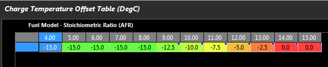
Charge Temperature Offset table is now 3D. Allows the Latent Heat of Evaporation to be corrected for different Fuel Type. This table can be imported from the Sample file.
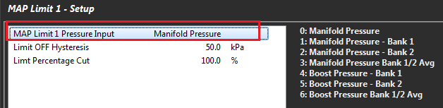
MAP Limit1 and 2 now have a selectable Pressure Input Channel.
NOTE: Please check this after the firmware update.
- Engine decoding added
- VQ35HR
- 3UZFE
- Jaguar V8 A27
- Honda VFR
- Ford Coyote V8 5.0L/Voodoo 5.2L
- Holden Ecotec
- BMW N52
- Toyota 2UR-FSE
- Mercedes AMG M156
- Toyota Variable Valve Timing - intelligent by Electric motor (VVT-iE ) added.
Fixes/Improvements
Traction Limiting Options.
- TC Limiting Ignition option fixed.
- TC Limiting Fuel + Ignition option fixed
*NOTE: - Please recheck the “Limit Type” and “Cut Pattern” Settings in the Traction Control Setup menu.
- DI3/4 on Exhaust CAM with Inj15/16 conflict fixed.
- Boost Control Lockout with Input Sensor failure or MAP Limit active.
V2.8.0 10/4/2017
- *Caution please read. - A new control strategy for generating the DBW Target control has been implement. This will require a setup change in most situations.
The new strategy involves demanding a Throttle Area using the Pedal to Throttle Translation Table (which directly relates to torque) and a 2D Throttle Area to Throttle Position conversion table.
a) The Pedal Translation tables have been renamed to “Pedal to Throttle Demand Translation” table. The table(s) generate a percentage Throttle Area demand between 0 and 100%.
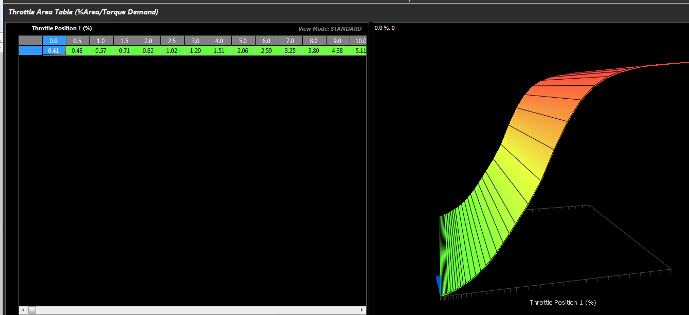
b) Throttle Area to Throttle Position correlation table. A new Throttle Area Table is then used to generate the DBW Target Throttle Position based on the Area Demand. The Default table is shown below. If the numbers are not initialised correctly after the firmware update, use the KV Sample file to import the table.
The Throttle Area to Throttle Position correlation table can be located in Engine Functions -> Throttle Body Model menu.
NOTE: This new strategy means the DBW Target Tables are no longer required and have been removed. ALL DBW Target control is done using the Throttle to Pedal Translation Tables.
\ - Please initialise/check this settings after the firmware update .*
- The ECU can model the Air Mass Flow (g/s) through the Throttle Body(s). The calculation used by the ECU is a direction derivation of the Navier-Stokes equations using pressure ratios and throttle area. The following settings are available:
- A Throttle Position to Throttle Area table as shown in 1b). Throttle area is a critical component required to calculate Throttle Mass Flow, so this table allows the correlation of throttle position to throttle area as a percentage. The table is located in Engine Functions -> Throttle Model menu.
- Throttle Diameter (mm). See Engine Functions -> Throttle Model menu -> Throttle Flow Setup.
- Throttle Body Scaler. Allow a percentage correction on the Throttle Diameter to correct small flow errors. See Engine Functions -> Throttle Model menu -> Throttle Flow Setup.
- Number of Throttle Bodies (1 - 2). See Engine Functions -> Throttle Model menu -> Throttle Flow Setup.
- Pressure Channel selection. The pressures before and after the Throttle Body(s) are required to calculate Throttle Mass Flow. See Engine Functions -> Throttle Model menu -> Throttle Flow Setup.
NOTE. On normally aspirated engines the pressure before the butterfly can be selected to Barometric(ECU Internal) so no additional sensors are required.
- ECU Torque Modelling. Changes have been made to the ECU Torque Modelling. The calculated Engine Torque in previous firmware versions has been calculated using Fuel Flow and BSFC. This has been revised and the ECU now uses Air Mass to calculate Engine Torque.
Engine Torque (Nm)
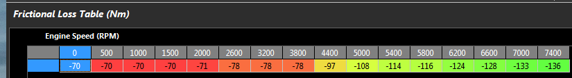
- Engine Torque = Ideal Torque - Frictional Loss. Frictional Loss is an estimate of torque required to overcome engine friction. Make sure the Frictional loss table has been initialised correctly. If required import this table from the KV Sample file.
Parameters used to calculate Engine Torque
- Current Air Mass of the Engine(Dependant on MAP, Inlet Temp, %VE, Engine Size, Number cylinder) which is the runtime “Modelled Air Mass”
- Lambda Target
- Stoichiometric Ratio
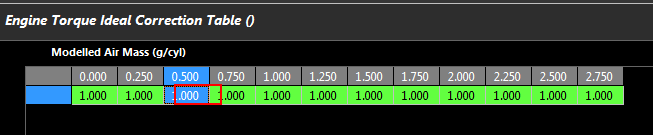
- A 2D table has been added to adjusted the Torque calculated by the ECU if required. See Tuning View -> Torque Management -> Engine Torque Ideal Correction Table. The Default values should be 1.000 and the x-axis. spanned using “Modelled Air Mass”. The table allows a percentage correction based on Modelled Air Mass.
Torque Demand (Nm)
The ECU calculates the best estimate of what the engine Torque Demand should be, based on the Ideal Gas Law and a derivation of the Navier-Stokes equation(s). Parameters used in these calculations are:
- RPM
- Engine VE
- Inlet Temp
- Boost Target (Represents Max expected engine load)
- Engine Size
- Throttle Area Demand (From Translation Table)
- Throttle Diameter
- Lambda Target
- Frictional Loss
See Runtime menu -> Calculated tab.

- A Charge Temperature Offset Table has been added. This can be used to offset the Charge Temperature. This offset should be applied to compensate for the charge cooling due to the latent heat properties in the fuel charge. Some fuels (such as Methanol) have an extremely high latent heat capacity Other factors such as Stoichiometric Ratio will influence the charge temperature. See Fuel -> Compensations.
- Boost Control Target can be selected as Absolute or Gauge. NOTE: The ECU will always generate the final Boost Target as Absolute value.
Absolute Mode.: This is the Target Boost Pressure *independent - of Barometric Pressure.
Gauge Mode. This is the Target Boost Pressure *above - Barometric Pressure
Example.
Absolute Mode. Target = 250kPa. The ECU will Target an Absolute pressure of 250kPa. Boost Pressure inside the engine will increase as Barometric pressure reduces.
Barometric Pressure of 100kPa. Boost pressure inside the engine will be 150kPa.
Barometric Pressure of 80kPa. Boost pressure inside the engine will be 170kPa. (250kPa - 80kPa)
Gauge Mode. Target = 150kPa. The ECU will Target a boost pressure of 150kPa above Barometric pressure.
Barometric Pressure of 100kPa. ECU Boost Target will be 250kPa, boost pressure inside the engine will be 150kPa.
Barometric Pressure of 80kPa. ECU Boost Target will be 230kPa, boost pressure inside the engine will be 150kPa.
\ - Please initialise/check this setting after the firmware update .*
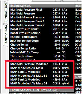
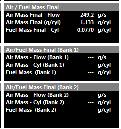
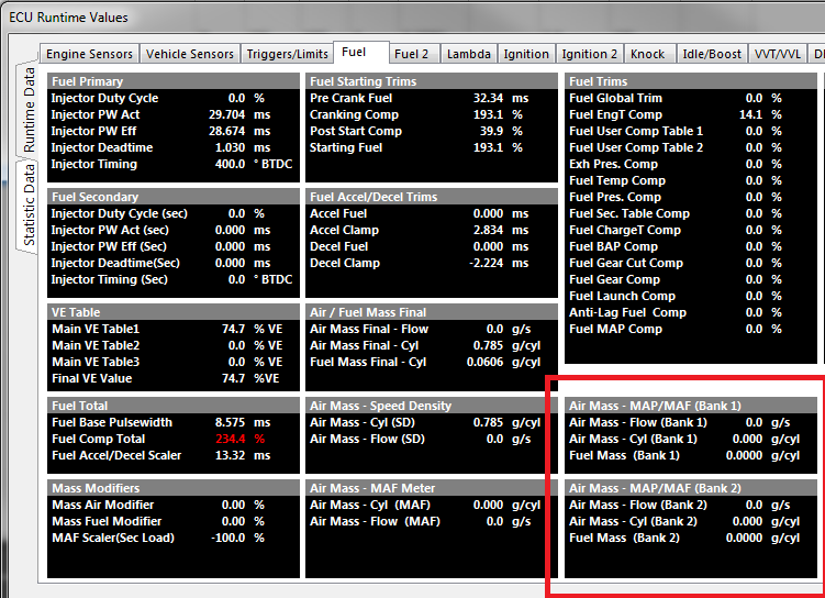
- Air Mass data now always displayed for any Load Input channel (MAP and MAF). See Runtime menu -> Engine Sensors Tab.
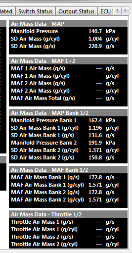
- Final Air/Fuel Mass data for single and banked Fuel Models displayed in the Runtime menu -> Fuel Tab.
- Fuel Model. Option 4 has been changed from “Blend MAP + MAF” to “Blend Modelled MAP + MAF”. Modelled MAP can be generated by the tuner using different sensors and gives greater tuning flexibility.
Fuel Model. Changed option 3 has been changed to “Blend Modelled MAP + Throttle Mass Flow”
Added pull-up control on User Position and Pressure channels.
EVO 10 Decoding adjusted to account for a 360 offset.
Anti-lag Ignition Retard clamp increased to 250%
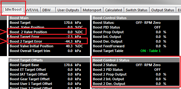
Added Dual Boost Control(Bank control). This option allows x2 individual Boost Control functions to operate using 2 different MAP pressure source inputs. Normally used to control boost pressure independently on each engine bank when there is no common plenum. New run times provide PID and duty cycle data for the 2nd Boost Control function.
V2.7.20 30/1/2017
Added Race Timer, Resolution of 1ms. See Tuning View -> Timer Function -> Fixed Timer setup. Runtime available in the Calculated Tab
Dodge SRT4 Engine Decoding added.
Added BMW S50 Dual Vanos Engine Decoding
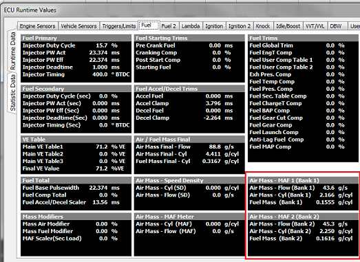
Added Dual Speed Density and Dual Mass Air Flow Fuel Model modes. Used to individually control fueling on each engine bank when there are individual plenum’s.
MAF Mode:
Input “Mass Air Flow Meter 1” controls fueling on Bank 1
Input “Mass Air Flow Meter 2” controls fueling on Bank 2
MAP Mode:
Input “Manifold Pressure - Bank 1” controls fueling on Bank 1
Input “Manifold Pressure - Bank 2” controls fueling on Bank 2
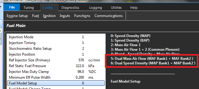
Individual air and fuel mass data is available under the Runtime menu -> Fuel Tab.
- More options have been added to the Efficiency and Load custom runtime:
Fixes/Improvements
- ECU logging gets paused while Scope Function is active
2 )Renamed Requested Torque menus to Torque Demand Translation
Improvements made to the On-board Lambda header and pump current control during sensor warm up.
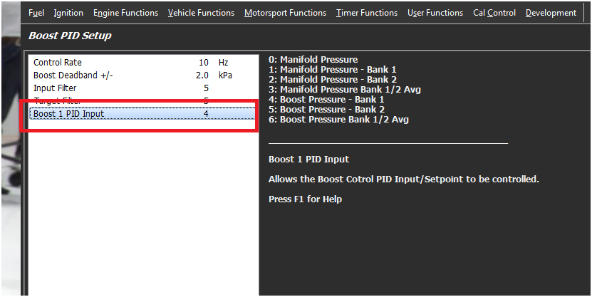
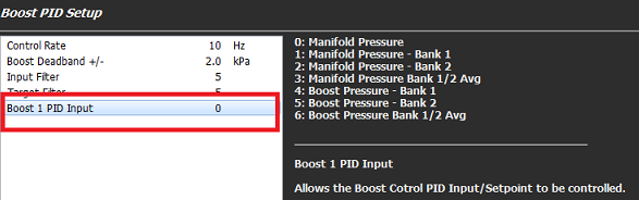
Fixed Open Loop Boost control issue introduced when the “Boost 1 PID Input” setting was added.
V2.7.4 23/11/2016
- Closed Loop Boost Control, PID Input channel is adjustable from the Boost Closed Loop Control -> Boost PID Setup menu.
Fixes/Improvements
Engine Start User Lockout not storing after ECU power cycle.
Toyota 2ZZ Trigger Decoding.
DBW1 and DBW2 Auto calibration.
User Knock Lockout setting has had its memory location changed. If Enabled, this setting will need to be re-initialised
EGT and Lambda Channels with Input Source on CAN Bus.
You can now Scale the CAN data in the Inputs form. This means the 2D Calibration table is used by the firmware and must be set correctly. If no scaling is required, then select
“Predefined Calibration” to read “CAN - EGT 1:1Scaling. This puts 1:1 scaling in the Calibration table as shown below.
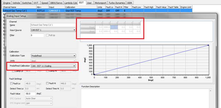
However, if you want to scale the CAN data, select “Calibration Type” to “Custom” which enables the 2D table for editing
V2.7.0 26/10/2016
- Dedicated Engine Protection Function added for the following:
- Engine Temperature
- Oil Pressure
- Fuel Pressure
- EGT (Max/Peak value)
DBW 1Throttle Blip Option added into the GearCut Function. See Config View -> Functions -> Motorsport Functions Tab - >GearCut Control
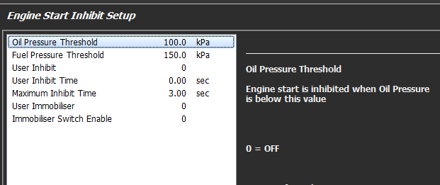
Added Engine Start Inhibit Function. Used on initial cranking to Inhibit/Stop the engine from starting until sufficient Oil Pressure and/or Fuel Pressure and/or Crank Time has been reached.
An Immobiliser option can also be enabled within this function. The Engine Start Inhibit function when ON, will disable Fuel and Ignition.
Torque Functional Loss table added. An estimate of torque required to overcome engine friction. This value gets subtracted from the calculated Engine Torque.
EGT Min runtime added.
Porsche 997 Engine Decoding added.
Speed Out Function. Engine Speed added as the Source Channel. Also added an Output filter setting.
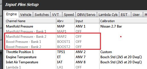
New Input IDs have been added:
- Manifold Pressure - Bank 1
- Manifold Pressure - Bank 2
- Boost Pressure - Bank 1
- Boost Pressure - Bank 2
- Additional Functionality added to DBW 2:
- Anti-lag Override and cooldown mode
- Throttle Blip (Gearcut and Gearshift)
- Idle Speed Control
- New Fuel Model mode added; “Mass Air Flow 1/2 Individual (Separated Plenum)”. On some engine configurations the plenum is not common and each bank operates independently. This Fuel Model allows ECU to independently control the Fueling for the Engine Banks 1 and 2 using two MAF Sensors . Dedicated runtimes also product Air and Fuel Mass information for each Bank.
- The Boost Control Input or Set point for the PID Control is now adjustable.
** \ - Please re-check this setting after the firmware update to make sure its set correctly for the application.***
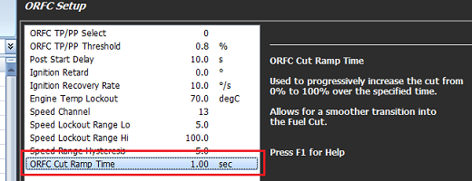
- Overrun Fuel Cut Ramp Time setting added. Allows the transition into Fuel Cut to be smoother.
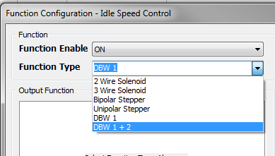
- DBW Closed Loop Idle Speed can now be selected to use both DBW 1 and DBW 2.
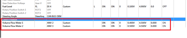
- Inputs for Volume Flow Meters 1 and 2 added. Scaling is L/min.
V2.6.0 6/6/2016
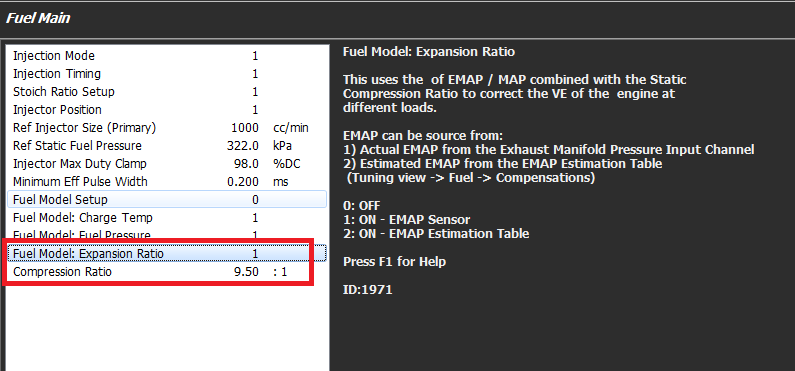
- Fuel Model. *Expansion Ratio Correction - has been added/included into the Fuel Model when switched ON. This uses the of *EMAP / MAP - combined with the engines *Static Compression Ratio - to correct the VE of the engine at different loads. The EMAP can be source from:
- Actual EMAP from the Exhaust Manifold Pressure Input Channel
- Estimated EMAP from the EMAP Estimation Table (this is new). This allows a sensor to be temporarily fitted to the exhaust, the pressure mapped and loaded into the table. The sensor can then be removed.
(Tuning view -> Fuel -> Compensations)
*NOTE. - This setting should be switched ON at the start of the tuning process.
- The runtime menu now gives more Runtime Data and Status Data on the parameters being used in the Fuel Model.. See the ECU Runtime menu -> Fuel 2 tab
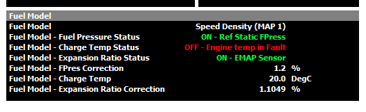
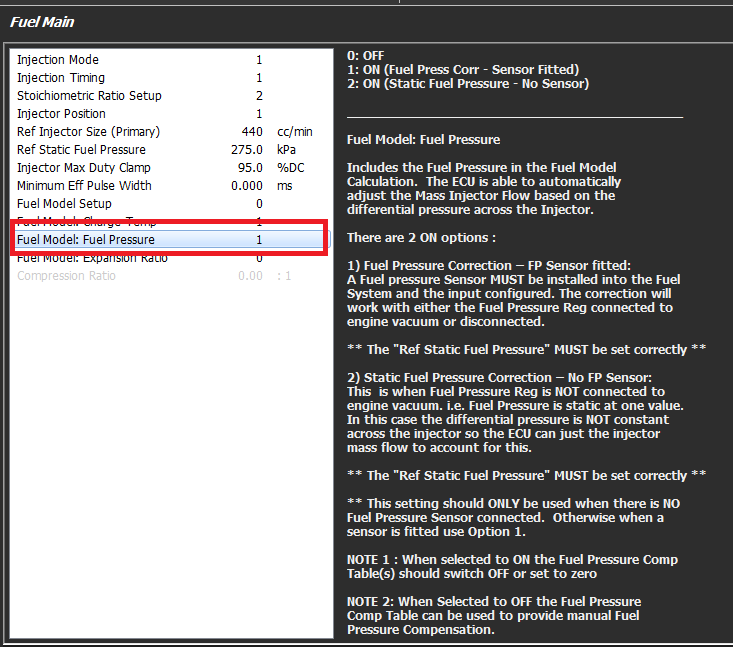
- Changes have been made to the Fuel Model - Fuel Pressure mode allowing Fuel Pressure Correction on fuel systems that run a fixed fuel pressure.
** \ - Please re-check this setting after the firmware update to make sure its set correctly for the application.***
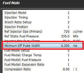
- Minimum Effective Injector Pulsewidth has been added.
** \ - Please check these settings after the firmware update to make sure its set correctly for the application.***
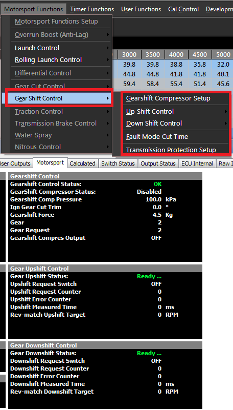
- *Gearshift Function - ready for Beta Testing using either Force or Paddle to initiate the cut. This Fuction is fully Closed Loop Control and uses gear position is used as the feedback to end a Gearshift
Request. Therefore the Gear Detection Voltage channel MUST be configured. See Inputs -> Vehicle Tab
A Throttle Downshift Solenoid can be used on non-DBW applications to manually open/blip the throttle on downshift. The ECU will control this as part of the Gearshift function.
Mechanical - Gear Shift Force: When Gear Shift Force is used an Input Source MUST be assigned to Gearshift Force channel.
Positive Force = Upshift Request
Negative Force = Downshift Request
Electronic - Paddle Shift- When Paddle Shift is selected the Up Shift and Down Shift channels MUST have an Input Source assigned.
The Runtime Menu (F3) provides a large amount of data including the actual gearshift time in milliseconds.
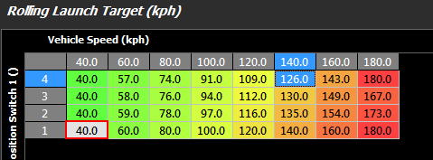
- *Rolling Launch Control - Function added. Rolling Launch Control will limit the Vehicle Speed once moving by limiting the Engine Speed.
The system becomes enabled when the Rolling Launch Switch is ON. When the switch transitions from OFF -> ON the ECU will record the current speed of the selected channel and this is used in a 3D Target Table to determine the actual speed limit. This allows either a 1:1 ratio (as shown below in switch position 1) or a custom ratio (switch position 2-4)
Support added for V16 engines. This includes wasted spark on Ignition channels 7,8 and sequential fuel on injection channels 13-16. Bank Trimming and Closed Loop Lambda added for cylinders 13-16.
Filter change to the Ethanol and Fuel Level Inputs. This now uses a cascaded integrator–comb filter implemented as a moving average filter. The Filter value represents the numbers of samples/stages in the filter.
Typical value for Fuel Level: 50 - 100.
- Launch Control Functionality change. ****\ - WARNING. This function will need to be reconfigured as there has been major functionality and upgrade changes *9
The Launch Control has been separated into 3 major functionality groups: Lockouts , Arming Control, Disarming Control.
- Lockouts prevent the system Arming or Disarming.
- Arming Control are settings used to “Arm” the system which make it active
- Disarming Control are settings used to “Disarm” the system which turn it off
The Runtime information has also been improved providing more information on the Launch System Status. (See F3 menu -> Motorsport Tab)
- Gear Runtime has had an offset change. Can now span -1 fro reverse , -2 for park.
** \ - WARNING. Any table axis spanned using gear will need to be reconfigured. An old gear axis value of 1 will now read -9 so an offset of 10 will need to be added to all axis values to make them correct***
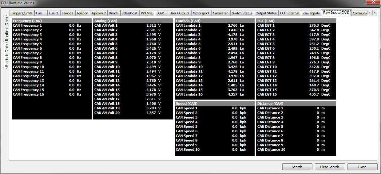
- Added *x64 Channels - of Input CAN based runtime data, giving a large Input Expansion to the ECU. See F3 Menu -> Raw Data(CAN). These inputs can be received and scaled using the new CAN Custom Receive Datasets 1-4
- x20 CAN Analog Inputs
- x16 CAN Frequency Inputs
- x16 CAN Lambda Inputs
- x16 CAN EGT Inputs
- x10 CAN Speed Inputs
- x10 CAN Distance Inputs
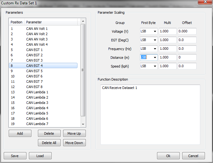
This CAN data can be received by the ECU using Custom Receive Datasets. There are 4 new CAN Receive Channels that can be configured to receive the following grouped data:
- Voltage
- EGT
- Lambda
- Frequency
- Speed
- Distance
Each Group can be scaled. 20 parameters are allowed per Dataset. Example shown below:
Gear Position can be calculated from either Voltage or Ratio (rpm/speed). Now both these calculations are done together which means both runtimes are always available.
ECU to Emtune Ethernet connection improvements in speed and smoothness (Requires FPGA Version 1.90 or greater)
ECU Logging changes
- Logging download speed has been improved by 50% (i.e now 50% faster)
- 32MB logging enabled for KV series
- Logging Continuous Mode enabled.
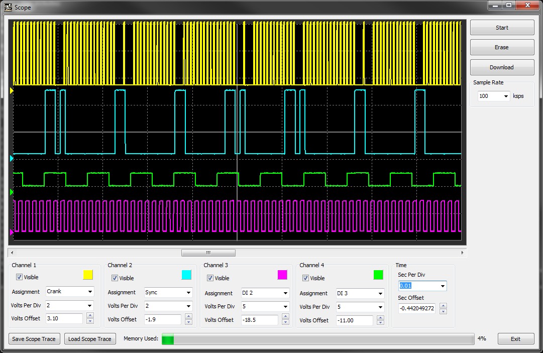
- ECU Scope Function (Requires FPGA firmware 1.90 of later). 4 Channels can now be sampled simultaneously up to 100ksps
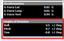
- New Input Channels added:
- Angles of Rotation, Roll, Pitch, Yaw. See F3 Menu -> Vehicle Sensors Tab. Setup from Config View -> Inputs -> Vehicle Tab
- Steering Angle (*NOTE: - For CAN Bus OEM applications this setting will need to be initialised. Select Input Source to “CAN OEM”)
- Gear Request Switch 1-5 Inputs
- Hill Start switch (for OEM applications)
- Clutch Position
Anti-Lag Change. On DBW applications pedal position is used to control Arming/Disarming conditions and Cooldown modes. More runtime data has been added.
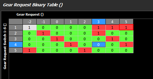
New Gear Requested function. This runtime can be generated by a Binary Position table or Paddle shifts. See Config View -> Functions -> Vehicle Functions 2 tab -> Gear Request Detection
When Binary Position is selected, the binary combination of the Gear Request Switch inputs setup from a table, can be used to select the Gear Request. In the picture below:
Gear Request -2 = Park when Gear Request Sw1 and Sw5 are ON
Gear Request -1 = Reverse when Gear Request Sw1 is ON
Gear Request 3 = 3rd when Gear Request Sw1 and Sw2 are ON ..etc
- New Gear Output Binary function. The BInary Combination entered into the Table controls which Gear Solenoids are ON and OFF.
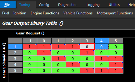
Example: When Requested Gear 2 selected, Gear Solenoid 1 and 4 are ON. All other solenoids are OFF.
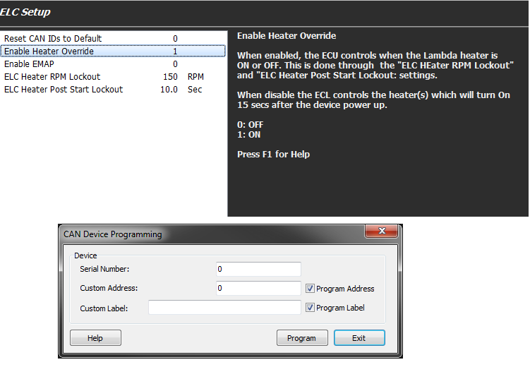
- ELC1 and ELC2 integration into the ECU
- Runtimes menu shows current Emtron CAN devices on the Bus
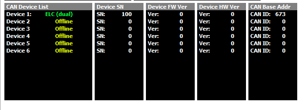
- ELC CAN Bus setup menu in the Config View -> Communications -> Emtron CAN Devices. From here you can Label each ELC device and change the CAN ID data is transmitted on. You can also control the operation of the ELC device(s) if required.
*Transmission Brake - function added. Commonly used function in Drag Racing applications where an Automatic transmission is used. A transmission brake is fitted which engages reverse and forward speed in at the same time to stop the vehicle from creeping on the staging line. To allow the vehicle to move during the pre stage period the ECU has the ability to momentarily allow the system to disengage before re engaging.
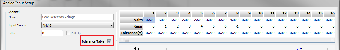
Gear Detection Voltage Input detection now has two options:
Gear Voltage (Tolerance Locked)
Gear Voltage (Tolerance Table)
“Tolerance locked” always uses the halfway voltage between 2 gears
“Tolerance table” gives adjustability using a table. Use the “Tolerance Table” check box to enable this Table.
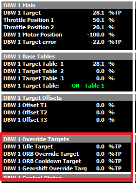
- DBW 1 Override Target runtimes now generated.
Engine Speed for every Cylinder is calculated for every cylinder. See the Runtime Menu (F3) -> Triggers/Limits Tab
Added Calibration data for Rotary Position Switch Inputs 1 and 2.
Trigger decoding Modes added:
- Suzuki M13A
- Suzuki M16A
- Mazda 2.0L
- Toyota 2GRFE
- Toyota 3URFE
- CAN Bus Decoding:
- Yamaha XYZ OEM
- Subaru MY10 Liberty
- Honda Jazz
- Yamaha YXZ - Plugin OEM integration
Fixes/Improvements
Fix 1 cylinder wasted spark application.
New CIC moving average filter added for Fuel Level and E85 Sensor.
Fix for Yamaha YXZ crank index offset not operating when engine speed outside the RPM Lockout value.
Fix to Lambda 1 and 2 channel scaling when Input Source selected as ANV15 or ANV16.
Fix for 5V Aux Regulator on Rev1 ECUs running the latest firmware.
Change to Engine Decoding labels for BWM models.
V2.5.0 19/10/2015
- DBW Closed Loop Idle Speed Control. This function has been enabled and available only on DBW 1. This function is enabled from the Config view -> Functions -> Engine Functions Tab -> Idle Speed Control menu.
When the engine enters Idle Conditions and DBW Target Table is switched from the normal DBW 1 Table 1 or 2 or 3 to the Idle Speed Initial Position Table
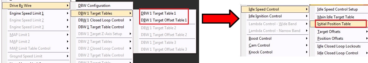
The Idle Speed Initial Position Table acts as a Feed forward table for the Idle PID Control. The Switching between these tables is controlled from the Idle Speed Lockouts Menu.
See the Plugin Sample Files for examples on these settings.
NOTE 1: It is advised to used a PI controller(put D-Gain at zero). Also keep Idle PI Gains small. See Plugin Sample Files for examples on these settings.
*NOTE 2: - If Idle Ignition Control is also ON, make sure the Idle Ignition I-Gain is set to zero so both Idle Ignition and Idle DBW systems are not flighting each other i.e. cannot have I-Gain active on both systems.
- In-depth Help has be written explaining the ECU’s different Fuel Models. This includes running the ECU using the MAF Sensor and Blend mode allowing the Speed Density calculated values and MAF sensor measured values to be blended. Select F1 on the Fuel Model Setup menu.
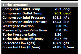
- Turbo Thermodynamic calculated runtimes have been added. This includes:
- Turbo Pressure Ratio (y-axis on Compressor MAP)
- Corrected Flow(x-axis on Compressor MAP)
- Adiabatic Efficiency
To calculate this data the following Inputs are required:
- Compressor Inlet Temperature (Ambient)
- Compressor Output Temperature
- Compressor Inlet Pressure (Baro)
- Compressor Outlet Pressure
This data can use overlaid on Compressor MAPs to look at the overall performance of the turbo.
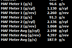
- ECU now supports 2 Mass Air Flow Sensor inputs. The ECU will sum these when the Fuel Model is selected to MAF Mode. See Runtime menu -> Engine Sensors
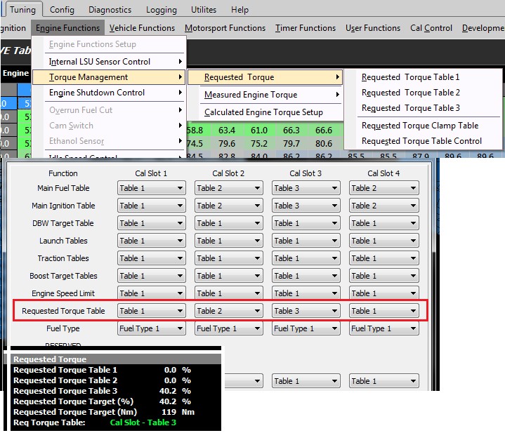
- New Torque Management Settings
a) Requested Torque Tables. Two more tables have been added giving 3 in total. These are now controlled using the “Requested Torque Table Control” option. This allows individual tables selection, or table selection controlled through the Cal Slot function. There are also new Requested Torque runtimes to match (see F3 menu -> Calculated Tab)
b) Measured Torque Tables. The Engine Torque can be entered into a Table. An Offset Table is also available allowing the Torque to be trimmed based on Ignition Angle for example. See KV Sample File.

c) Calculated Engine Torque. Using inputs from Injector Size, Injector Duty, Fuel Density, Lambda Target and estimated BSFC at lambda 1.000, the ECU generates a calculated/estimation of Engine Power and Torque.
Settings can be adjusted from the Engine Functions -> Torque Management menu.
- On board Accelerometer.
- The ECUs x/y/z Axis can be adjusted/swapped to matched the vehicles Long/Lat/Vert Orientation. These new settings are available from Vehicle Function -> Accelerometer Menu.
Filtering options have been enabled for each axis, from each corresponding Input Setup Menu. Value 0 - 30 can be used. The higher the number the more filtering.

- Lambda 1 and 2 Input Channels changes:
- DTC Codes added for Lambda 1 and 2 Inputs.
- Clearing of all Short and Long term trims when the sensor(s) faults(when DTC gets generated). Closed Loop Lambda is also disabled.
- Can now do a manual sensor calibration with the engine is running. The system will re-enter the heater warm-up phase when the calibration is switched OFF.
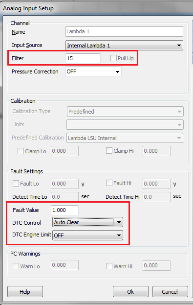
- The FIlter, Fault Value and DTC menus options are now available when the Input Source is set to “Internal Lambda 1/2”
- Added DBW1 Minimum Target Clamp. Can be adjusted from the DBW 1 PID Setup menu.
Some DBW throttle bodies have non-linear behavior when the plate is close to fully closed. This makes functions like Closed Loop DBW Idle unstable as the
plates response is unpredictable. The setting clamps the minimum Target value and stops the plate entering this region.
- New Runtimes (requires FPGA firmware 1.81 or later):
- New runtime data displaying Fuel and Air Mass data for MAF and Speed Density Fuel Models. Also added Mass Modifiers. See Runtimes Menu (F3) ->Fuel Tab.

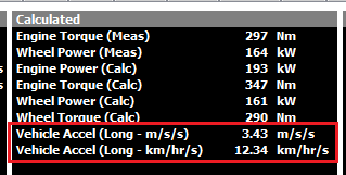
New Acceleration values under the Calculated Tab. The Accel calculation uses the Longitude g-force from the on-board accelerometer to calculable vehicle acceleration in units of m/s/s or Km/hr/s. For example acceleration of 1g equates to 35.3 km/hr/s. This means the vehicle is accelerating at 35.4 km/hr every second.
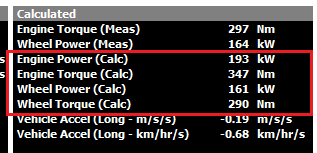
New Calculated Engine Torque data.
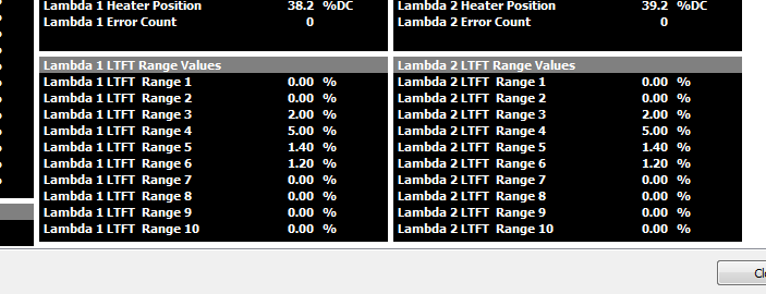
Lambda 1 and 2 LTFT range values:
- Engine Start Control Function. This now has an On/Off control, selected from the Functions -> Vehicle Functions 2 Tab.
WARNING. If the Engine Starter Relay Output is being used, this function will now need to be switched ON to enable it.
Also extended the number of inputs that can be used to control this function. Now both the “Start/Stop Switch” and “Start Position Switch” can be used to control this function. See the Help for more information.
- DTC codes added:
- ACD Pressure Input
- Rotary Switches 1 and 2 Inputs.
- Lambda 1 Input with Internal option selected. Fault Value, DTC Control and DTC Engine Limit options available. See the Input Setup menu.
- Lambda 2 Input with Internal option selected. Fault Value, DTC Control and DTC Engine Limit options available. See the Input Setup menu.
- MAF Sensor 2
- Added Active Center Differential (ACD) control for the hydraulic pump. Enabled when the Motorsport Differential Control Function is ON. A Table can be used to set the Pump Target Pressure for varying conditions.
See F3 menu -> Motorsport Tab for runtimes.
Two new Rotary Switch Inputs have been added. These can be edited from the Inputs Pins Setup -> Vehicle Functions 1 Tab. Rotary Switch position can be viewed from the Runtime Menu -> Vehicle Sensors Tab. Table axis control is also available for this input.
New Pedal Position Closed Fixed timer. See Tuning View -> Timer Functions -> Fixed Timer Setup
New “Custom Runtimes” menu. See Config View -> Inputs -> Custom Runtimes. Currently moved the “Efficiency Calculation” and “Load Calculation” into the menu. More runtime to follow.
CAN Bus 2, Channels 3 and 4 enabled.
Engine Decoding mode(s) added:
- Toyota 3URFE Quad VVT.
- LS1
- User Output Functions now have x2 PWM Modes:
- Fixed Frequency with 3D Table for Duty Cycle Control.
- Fixed Duty Cycle with 3D Table for Frequency Control; range is 0 - 1000Hz. (new mode)
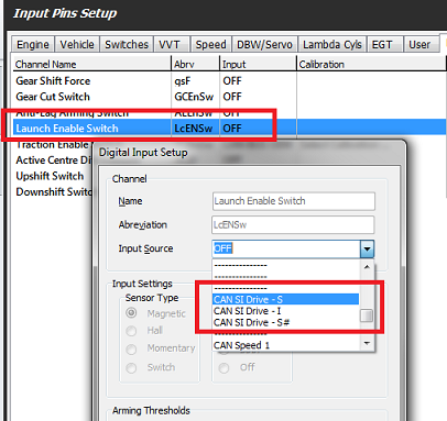
Subaru MY15 and MY12-MY14 CAN Bus decoded.
Subaru SI Drive modes (Sport, Intelligent, Sport Sharp) can be selected as a source channel on Switched Inputs.
Fixes/Improvements
- When the Lambda 1 or Lambda 2 sensor enters a fault condition, ALL Closed Loop Lambda trims are cleared to zero (and DTC will be generated)
- Accel Mode. Option 1 and 2 were swapped in the menu description(MAP and PP1). To clarify: value 0 = TPS 1, value 1= MAP, value 2 = Pedal Position 1
- Hard/Inconsistent starting on Distributor Ignition mode.
V2.4.0 24/7/2015
The number of degrees over which the Engine Speed is calculated has been made user adjustable. See Config View -> Engine Decode Setup -> Sensor Main.
Engine Decoding modes added:
- Nissan VK45/VK56
- Mazda 3 LF Series Engine Decoding beta.
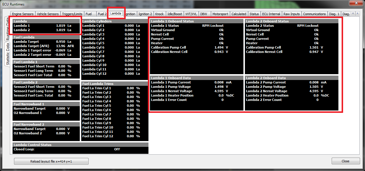
- On-board/Internal Lambda Control Changes
Simplified enabling on the dual On-board Lambda Function. The ECU now automatically assigns the correct the Heater Output Channel based on ECU Type and Serial Number. The only setup required to enable the Internal Lambda 1 or 2 control is from the Config View -> Inputs-> Engine tab.
- If “Lambda 1” Input Channel has the Input Source selected to “Internal Lambda 1” the function becomes enabled.
- If “Lambda 2” Input Channel has the Input Source selected to “Internal Lambda 2” the function becomes enabled.
- Sensor Calibration. The Lambda Sensor(s) can now be automatically calibrated every time the ECU Powers ups if enabled. Controlled from Tuning View->Engine Functions -> Internal LSU Sensor Control.
Remember that all the On-board/Internal Lambda data is available from the F3 menu, Lambda Tab.
CAN Bus OEM implementation for the Nissan D40 truck.
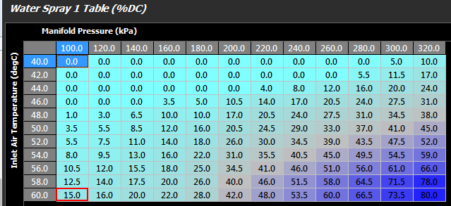
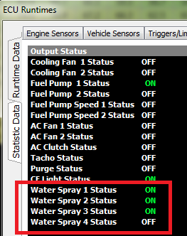
Motorsport Water Spray Function added. There are 4 individual channels available. These can be used to spray the Intercooler, Brakes, Radiators etc. Lockout conditions Enable/Disable the function. Once enabled a 3D table can be used to adjust the output Duty Cycle. The ECU Runtime menu -> Status Tab will provide function status information.
- CAN Bus OEM models added:
- BMW
Fixes/Improvements
- DBW 2 Offset Tables 1,2,3 fixed. NOTE. Please recheck Table Axis settings if these tables are used
- DBW2 Offset Tables 1,2,3
- Accel/Decel Tables
V2.3.0 1/5/2015
- Exhaust Pressure Correction tables added for Lambda 1 and Lambda 2 Inputs. The correction can be enabled from the Config View, Lambda 1/2 Input Setup Form. An Exhaust Pressure Sensor must be fitted to use this function. An Absolute Pressure Sensor MUST be used.
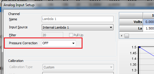
There are two tables to select from; Rich and Lean. Table values will be initialised after a firmware upgrade. Sample values can also be used from the KV8 sample file.
NOTE:
When Wideband sensors are used in turbocharged applications, be aware that the sensor itself is sensitive to the back pressure of the exhaust. ie A positive exhaust back pressure compared to what the sensor was calibrated at, will cause the sensor to read differently. Increases in pressure cause the sensor to read farther from stoichiometric eg.
- A rich reading will appear richer than it really is.
- A lean reading will appear leaner than it really.
Brake Pressure Inputs have had more high pressure sensor options added; the Bosch 250Bar: 0-265-005-303 250Bar and Bosch 140Bar: 0-261-545-053. Units for these high pressure sensors have been changed to Bar and PSI
A 4th option has been added to the “Pre-Crank Injection Enable” setting. This allows multiple “First Crank” events to trigger the Pre-Crank injection function.
NOTE: Option 2 allows the Pre-Crank injection function to trigger ONLY once while the ECU is powered.
Fixes/Improvements
ECU Logging changes to the storage of the PID Header.
Gear Cut Status in the Runtime F3 menu.
V2.2.0 17/3/2015
Traction Control release 1. Based on %Slip. Additional modes will be added in future releases.
DBW 1 and 2 feed forward value(s) now have available a 3D Table giving greater flexibly when tuning the PID algorithm. This will improve dynamic response on both the plate opening and closing times. ****THE NEW TABLE(S) WILL NEED TO BE INITIALISED / CHEKCED. DEFAULT VALUE SHOULD BE SET TO 5.0%. WITH THE AXISES DISABLED THE TABLE CAN OPERATE AS A SINGLE ZONE SETTING. ****
Launch Control.
- More Arming/Disarming options have been added.
- Launch Mode added into the Launch Control setup menu, config view.
- Both Ignition and Fuel Cuts can operate simultaneously when the system is armed. Ignition cutting can provide the primary limiting to maintain the Launch RPM, while softer Fuel cutting can be used to ensure minimal plug contamination. See the Sample KV8 file for default settings.
- Disarm delay added. Allows for advanced Table Switching options during the Disarming process.
- Launched Armed On/Off Status added to Axis control and User functions.
The Input Calibration Table(s) for Lambda Cyl1 -12 and EGT Cyl 1-12 have had a format change. These will need to be reconfigured if they are used.
The following Input Channels have been added under the new Turbo Dynamics tab:
- Turbo Compressor Inlet Temperature
- Turbo Compressor Outlet Temperature
- Turbo Compressor Inlet Pressure
- Turbo Compressor Outlet Pressure
- Wastegate Position Sensor
- Pressure Bypass Valve Position
DTC’s have been added for the new Inputs listed in 4). The DTCs will need to be cleared after the update.
Added Min and Max %Cut settings to the AntiLag Cooldown mode (Cyclic Idle control).
Added Holden Alloytec Engine Decoding.
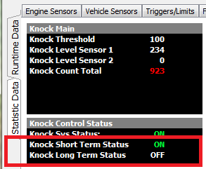
Knock Control. Two new Status Flags have been added. “Knock Short Term” and Knock Long Term. These get set to ON if any Knock Short/Long Term Ign Trim is not zero. i.e when the knock control is active and retarding ignition timing. One possible use is to span the Lambda Offset Table with this status so the Lambda Target can be adjusted during a Knock event.
Fixes/Improvements
- Engine Speed Limit 2 and 3 Turn On Delay. Delay was only working on the first pass through the limit.
V2.0.10 19/1/2015
- Increased DBW 1 PID displayed rate to 50Hz.\
- Added 3D Table for DBW 1 Feed forward (beta)\
- Traction control refinement before release.
V2.0.9 19/12/2014
- BWM M54/M52 Engine decoding added.
V2.0.8 08/12/2014
Honda B16 Engine decoding added.
Kawasaki Ultra 310 Engine decoding added.
GMx7 (6+1) Engine decoding added.
V2.0.7 21/11/2014
Added Filter setting for slip calculation.
Traction Control ready for Beta testing
Quad DBW ready for Beta Testing. Added Input Channels for Throttle Position 5-8 for DBW channel 3 and 4. Matching DTC codes also added.
CL Narrow Band now working on Sensor 2 and Sensor 1 + 2 modes.\
Added another Engine Decoding diagnostics counter.
**\ - Narrow Band Heater PWM tables have changed .. These will need to be re-initialised if they are used.
Fixes/Improvements
- Fixed Purge Table .. can now use a 3D Table to control solenoid %DC. Purge Control available on all Aux/Fuel/Ign Channels.
V2.0.6 22/10/2014
New initialisation firmware for Quad DBW.
Added more parameters to the Axis Control: DI Voltages, Knock Control data
V2.0.5 7/10/2014
- Boost Target Clamp Table added
V2.0.2 1/10/2014
Fixes/Improvements
- Fixed Launch Disable Speed setting … this setting will need to be rechecked/re-initialised
V2.0.0 15/9/2014 - Major Release
- *****\ - ECU Logging release - 16MB ******.
V1.1.138 14/9/2014
Subaru EZ30 Trigger decoding added.
Enabled “User Output Function 1-10” Table Control on the following *Fuel - Tables:
Fuel Sec Load Table
Fuel Exhaust Pressure Comp Table
Fuel Temp Comp Table
Fuel Pressure Comp Table
Fuel Gear Comp Table
Fuel User 1 Comp Table
Fuel User 2 Comp Table
- Enabled “User Output Function” Table Control on the following *Ignition - Tables:
Ignition Sec Load Table
Ignition Crank Comp Table
Ignition Post Start Comp Table
Ignition Engine Temp Comp Table
Ignition Charge Temp Comp Table
Ignition MAP Comp Table
Ignition Exhaust Pressure Comp Table
Ignition Gear Comp Table
Ignition User 1 Comp Table
Ignition User 2 Comp Table
V1.1.137 11/9/2014
BMW OEM Vanos Control added to the Exhaust Cams.
BRZ/GT86 Trigger decoding added.
Changed Max EGT runtime to Peak EGT.
DBW 2 now has PID control independent of DBW 1. This means DBW 2 PID control can either use the Tables from DBW 1 or 2. The following new tables have been added:
- Proportional Gain Table
- Integral Gain Table
- Derivative Gain Table
- Min Duty Clamp Table
- Max Duty Clamp Table
- Positive Integral Limit Table
- Negative Integral Limit Table
V1.1.136 6/9/2014
- Nissan 360 Engine Decoding added.
Fixes/Improvements
- BMW Vanos Control switches both Retard and Advance Solenoids off when rpm is zero.
V1.1.133 25/8/2014
Subaru EZ30/EZ36 Engine Decoding added.
Subaru factory CAN Bus decoded for 2007 - 2014 models.
Fixes/Improvements
Honda K20/K24 final engine decoding release
Engine Start/Stop function final release.
V1.1.126 13/8/2014
Fixes/Improvements
- BMW S62 Vanos Control .. when lockout mode active the ECU forces 20%DC on the Intake Retard solenoid to ensure the Intake Cam is fully retarded and applies 20%DC to the Exhaust Advance Solenoid to ensure the Exhaust Cam is fully advanced.
V1.1.125 9/8/2014
BMW S62 Engine Decoding added\
BMW Vanos control change on Inlet LH and RH(solenoids off during deadband + user adjustable feedforward)
ECU Logging firmware continues in preparation for release.\
Fixes/Improvements
Function channel assignment on Ignition channels 4-8
Conflict issue when a Function and Fuel Channel have the same Injector Output assigned .. Fuel Channel takes priority.
V1.1.122 1/8/2014
- Added Engine Start Function. Uses a new Input Channel called “Start/Stop Switch” and Output Function called “Starter Relay Control”. More info can be found at: Engine Start Control
****\ - Please check this setting new settings are initialise if required *****
Fixes/Improvements
Narrow Band heater control PWM Duty cycle out by 1dp.
Visibility control for Narrow Band 3D Heater Tables.
V1.1.121 1/8/2014
Added Fuel and Ignition ʺInhibitʺ Status to the runtime menu (F3).\
Subaru 2.0L Quad AVCS Engine Decoding.
Added VVT Exhaust Target Z-axis Control.
Fixes/Improvements
VVT Inlet and Exhaust Offset tables.
Auxiliary Channels 13 and 14 incorrect output polarity when used in switch mode.\
BMW Vanos Control.
V1.1.118 22/7/2014
Enhancements added to the Ignition Distributor mode.
Individual Cylinder Trims (a 720 sync is required)
Knock per cylinder (a 720 sync is required)
Dwell per cylinder (a 720 sync is required)
Spark Duration Setting for Distributor Mode .****\ - Please check this setting under Ignition -> Ignition Main.*****
BMW S54 Trigger Decoding added.
Ignition Channels 9 -12 on the KV12/KV16 can be assigned to other functions and used for PWM or On/Off control.
V1.1.116 14/7/2014
Added pull-up control on the following Input Switches: NOS Switch, Traction Control Switch, Brake Switch 1 & 2, Dual DBW Switch.
Pre-crank prime now supports multiple pulses to assist with cold starting. See Fuel -> Starting -> Starting Setup. The Pulse Count of 1 will retain the original pre-crank fueling. ****\ - Please check this setting *****
Fixes/Improvements
Short Term Fuel Trim (STFT) always cleared on a lockout condition.
Any Engine Limiting will lockout the Closed Loop Lambda Control.
LTFT now “holds” its value when STFT is less than “Min STFT lockout (+/-)” settings.
Post Start Delay on Idle Ignition Control.
Pre- Injection Table x and y boundaries incorrect memory locations. After this firmware update the ECU will copy the old settings into the new locations. \ - Please re-check this table(s) under Fuel->Starting->Pre- Injection Comp Table 1 & 2 .*
Overriding Crank Index and Sync Sensor Input settings when the sensor type is selected as magnetic - Pull-up always set to OFF and Edge always to Falling. These menu items are disabled in Emtune to prevent the use of incorrect setting.
V1.1.115 8/7/2014
Speed Limit Function enabled. Table1 and 2 are available for use allowing the tables to either operate independently or together to produce a single speed limit value. “Speed Limit Enable Switch” can also be used for pit lane limiting.
CAN 1 Channels 4-6 enabled.
Added Vehicle Functions -> Calculations -> Fuel Used menu . ʺReset Fuel Used” and “Percentage Correction” adjustments are now available.
Distance Calculation now available. Adjustments from Vehicle Functions -> Calculations -> Distance. ʺReset Distance” and “Percentage Correction” adjustments available. See Runtime Menu -> Calculations Tab for this runtime.
Max EGT added which is the Max value of any enabled EGT Channel. Always cleared on ECU Power up.
Drive Slip added to Axis Control and CAN datasets.
Fixes/Improvements
Gear Force DTC added
Gear Cut Timeout time was not operating correctly in all modes
CAN Custom Datasets limiting to 3 sequential PIDs
Engine Fan ʺON Temp Override” functionality fix.
Injector Linearisation Tables have been changed allowing both positive and negative numbers to be entered. \ - Please re-check these settings.*
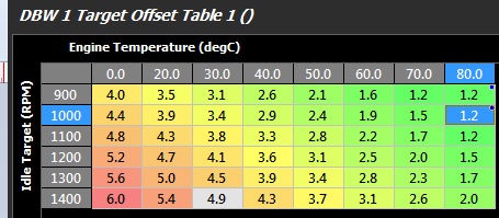
Startup RPM Target Offset was not working in DBW mode. This setting allows the Idle Target RPM to be increased during crank and for a short time post crank giving an adjustable Idle increase as the engine bursts.
**NOTE. Adjust this setting from Engine Functions -> Idle Speed Control -> Target Offsets -> Startup Offset Target RPM. Normally the DBW 1 Target Offset Table1 is spanned from “Idle Target” so an increase in RPM
Target during crank and post start will provide the required engine flare. A DBW table example is shown below:
V1.1.111 28/6/2014
ECU logging Setup Form Implemented. ****\ - Please select the ECU logging Setup menu (Logging -> ECU Logger) and make sure all 6 channels are OFF until the full functionality has been implemented. ****
Added Fuel Used runtime to the CAN datasets.
Yamaha Jetski FZR engine decoding added.
Fixes/Improvements
DBW Offset Tables now working in Z-axis Mode.
Close Loop Lambda Control “hold” mode added during sensor shutdown (occurs when the sensor is incorrectly positioned in the exhaust and gets thermally shocked.)
Internal Lambda PID heater gains reduced slightly.
V1.1.110 23/6/2014
LS2/7 engine decoding added
Added BAP mode to Fuel Model Setup (Can be used in TPS mapping)
When the Ignition Switch is enabled and toggles from OFF -> ON and the ECU already powered up, the fuel pump(s) will re-prime (Used in Motorsport applications when the ECU is always powered on)
“Used Fuel” runtime added. ECU calculates this by summing each effective injector pulsewidth and using the injector size to give a very accurate estimation of Used Fuel. See Runtime menu (F3) Calculations tab.
Added Fuel Used Reset Switch
Added Handbrake Switch\
Fixes/Improvements
- User Outputs Channels 1-4 Switch ON and Switch OFF Timer issue.
V1.1.109 09/6/2014
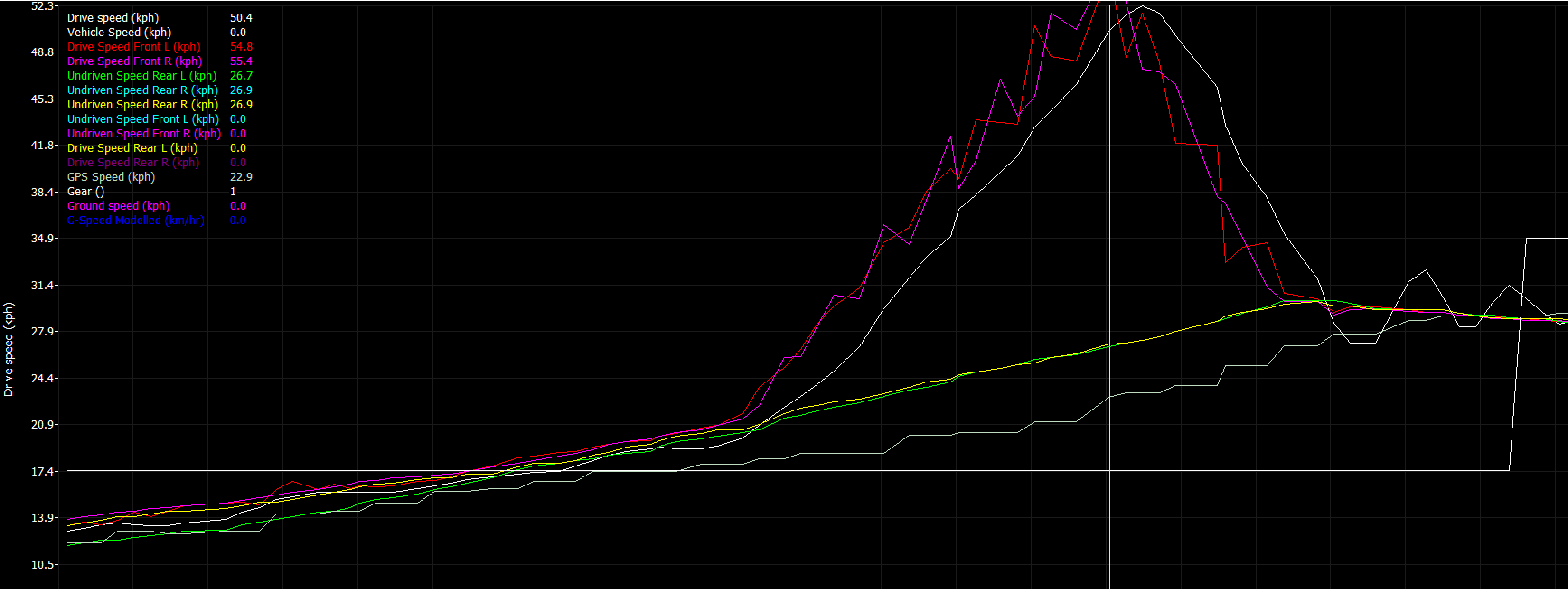
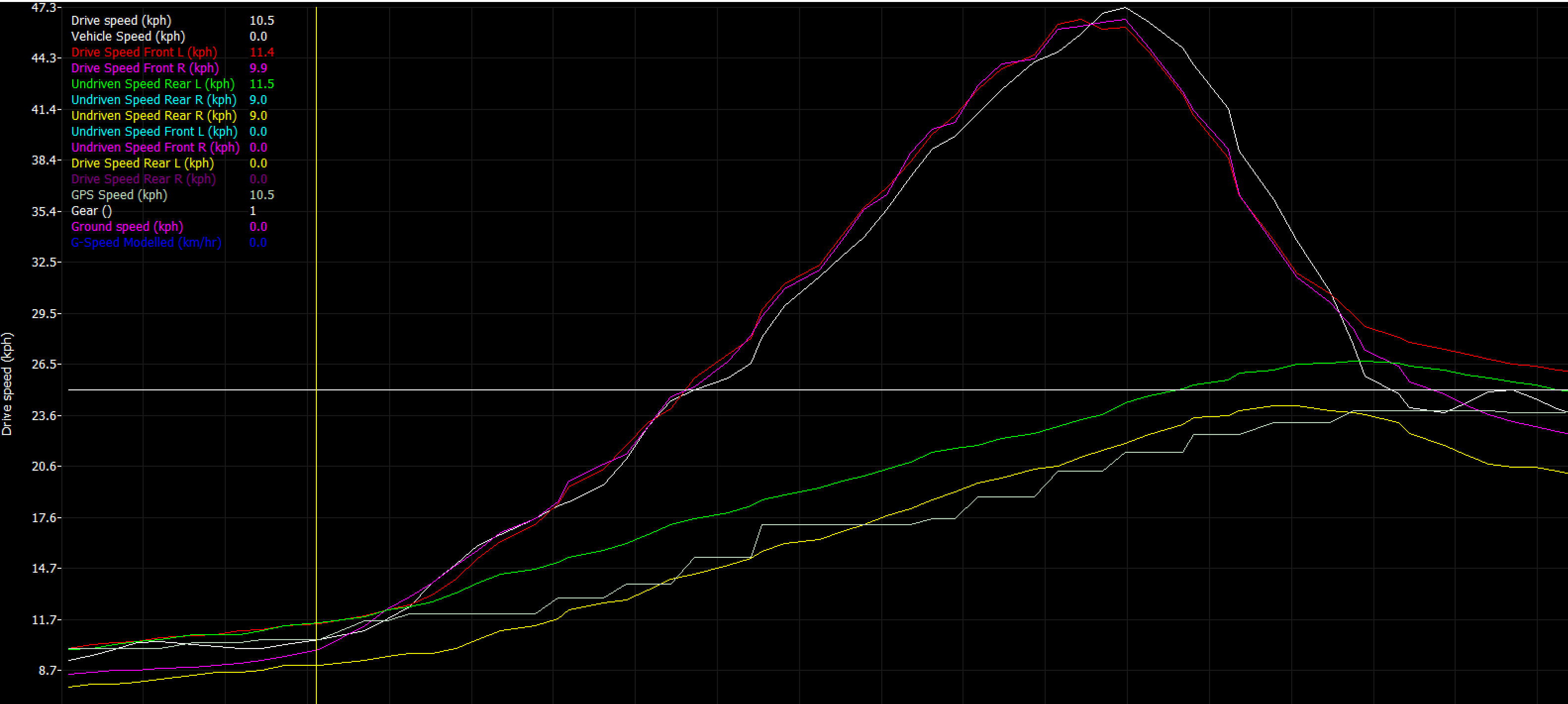
New Speed Input channels added: Undriven Speed Rear L, Undriven Speed Rear R, Vehicle Speed. These are available from Config view -> Inputs Pins (F10) -> Speed Tab
New runtimes added:
- Front Axle Speed. This is the average of either the Drive Speed Front L+R OR Undriven Speed Front L+R.
- Rear Axle Speed. This is the average of either the Drive Speed Rear L+ R OR Undriven Speed Rear L+R.
The ECU automatically checks which channels are assigned before generating the Axle Speed.
- Cornering Speed L. The average between the (Drive Speed Front L or Undriven Speed Front L) and (Drive Speed Rear L or Undriven Speed Rear L)
- Cornering Speed R. The average between the (Drive Speed Front R or Undriven Speed Front R) and (Drive Speed Rear R or Undriven Speed Rear R)
The ECU automatically checks which channels are assigned before generating the Cornering Speed.
- Drive Slip % calculation now available. Adjustable under the Motorsport Tab, Tuning view
All new data can be viewed from the ECU Runtimes menu (F3), Vehicle Sensors tab.
Changes
- The position of the Internal G-Force data in the Axis Control menu and User Outputs has been moved. If this data is used to span a table or control an output it will need to be reconfigured.
- The Cal Slot Control Enable has been moved to the Config View -> Functions Tab
V1.1.108 26/5/2014
- Sequential Primary/Grouped Staged Fuel Mode added. For example on a KV12: x8 Primary Injectors can be used with 4x Grouped Staged Injectors. On KV16, 12 cylinder engine: x12 Primary Injectors and 4 Grouped Staged Injectors.
V1.1.107 22/5/2014
- DBW Throttle Blip function added for Up Shift and Down Shift.
V1.1.106 15/5/2014
EVO 10 Trigger Decoding Beta Version.
BMW S65 Trigger Decoding added.
V1.1.105
Rx8 OEM CAN bus implemented. This includes full dash functionality(Tacho, Speedo, ECT Gauge, OilP Gauge & Light, CEL, Battery Light), electric power steer control, reading of 4 wheel speeds, steering angle .. etc. )
Toyota GT86/BRZ OEM CAN bus started
V1.1.103
- Ignition Channels 11 and 12 completed
Fixes/Improvements
- Fixed Lambda Target Z-Axis Control
V1.1.100
Injector Linearsation 2D Table control finalised for Primary and Secondary Injectors. (See KV8_Sample Cal file for a setup example)
Sequential Staged injection control added.
- Controls up to 12 injectors on a KV12 which is x6 Primary Injectors and x6 Secondary Injectors.
- Controls up to 8 injectors on a KV8 which is x4 Primary Injectors and x4 Secondary Injectors. *\ - Secondary Cylinder Injector Pulsewidths are given in the Runtime Display(F3)
Fuel Cylinder Bank trimming is implemented on Cylinders 1-12. Cylinders can be assigned to Bank 1 or Bank 2 from the Config View -> Engine Setup menu. Normal Table Control is used to control this function, adjusted from Tuning View Fuel ->Fuel Table Control menu. Bank Cylinder Trims are also given in the Runtime Display(F3)
User Timers 1 -5 Implemented. Switched on from Config View Functions -> Timer Functions Tab
User Outputs now have addition functionality… ON Delay and OFF Delay. For example the OFF delay can be used as hysteresis control .
E888 now supported
Fixes/Improvements
Fixed knock “Post Start Delay " setting
Internal Lambda 1 and 2 hide all status info when the function is OFF. Also forces a default calibration for Nernst and Pump voltages if they are outside the expected range.
CAN Channel Direction has been spit into 3 options 1) Receive, 2) Transmit, 3) Receive and Transmit.
This means on OEM CAN applications a channel can receive only, transmit only or do both.This gives greater flexibility to the user. *\ - PLEASE RE-CHECK CAN SETTINGS **
V1.1.97 30/3/14
- Lambda Offset Table 2 fix
V1.1.96 28/3/14
Fix Exh RH Cam Pullup Control not working
Dual Tune Switch implemented
V1.1.95 25/3/14
- Injector Linearisation beta for primary and secondary injectors
V1.1.94 24/03/14
Added a second Lambda Target Offset Table.
THESE SETTINGS WILL NEED TO BE INITIALISED WITH VALID VALUES*
Input Channel “Front Brake Pressure” now accepts data over the CAN bus i.e Subaru MY12
V1.1.92 20/03/14
INPUT Channels ʺInlet Temp Before ICʺ and ʺIC Water Temperature added. DTC’s also added
THESE SETTINGS WILL NEED TO BE INITIALISED WITH VALID VALUES*
10 User Inputs Channels are now implemented
a) x4 User Temperature inputs, b) x4 User Pressure inputs, c) x2 User Position inputs. ALL corresponding DTC’s added
THESE SETTINGS WILL NEED TO BE INITIALISED WITH VALID VALUES*
V1.1.91 17/03/14
Differential Control function added **THIS SETTING WILL NEED TO BE INITIALISED WITH VALID VALUES. IN THE CONFIG VIEW -> FUCNTIONS -> MOTORSPORT TAB MAKE SURE THE FUNCTION IS OFF ***
Added AC Pressure Sensor Input THIS SETTING WILL NEED TO BE INITIALISED WITH VALID VALUES*
Added EGT Cylinders 1-12 functionality.
Added DTC codes for AC Pressure Switch and EGT Cylinders 1-12
Added more accelerometer control options for the ECU’s internal sensor
Added “Handbrake Switch” Input
Added Steering Angle to table Axis Control
Added help and g-force setup, Differential Control and Fuel Overview
Fixed Fuel and Ignition Inhibit functions.
Locked inputs Manifold Pressure and Fuel Pressure to units of kPa.
V1.1.90 10/03/14
- Adjusted Decoding Multi-tooth Missing/No sync
V1.1.89 7/03/14
** * - 1) 13B Trigger Decoding added
2) 2 Stroke Mode implemented

3) Clamped Injector Timing to Max 360 when in 2 stroke mode
V1.1.88 7/03/14
** * - 1) ORFC fix. In some situations it would not trigger.
Added KV12 Ign 11/12 setup.
Added Test Inj/Ign for Cyl11/12
V1.1.85 28/02/14
** * - 1) Launch Control Table control functional
- Launch Select Table functional
V1.1.84 27/02/14
1) Added CL lambda Lockout when AntiLag Cut >0 or Retard > 0 or Fuel != 0 or in cool down mode
Software Note: Moved some INPUTS IDs from switches into Motorsport Tab ..
Cool Down Table working
Add TPS Lo and TPS Hi in Cool Down mode
Added 22 switch options to the Axis Control
Added ““Cooldown Always on”” option
Runtimes (F3) Motorsport AntiLag window now contains ALL relevant data
Stop DTC’s being sent to the ECU on a “Send File to ECU” command.
Added INPUT ID EGT 1 and EGT 2. Required for Anti lag.
MUST INITIALISE THESE SETTINGS FOR ANTI LAG TO FUNCTION CORRECTLY
- Implemented EGT lockouts in Antilag which control Arming and Disarming
MUST INITIALISE THESE SETTINGS WITH VALID VALUES
- Anti-lag Table control and software menus added.
V1.1.80 25/02/14
1) Anti Lag Revision 1 beta version

2) EVO 9 Trigger decoding revision for fast start
V1.1.78 16/02/14
- Added LTFT table functionality
V1.1.76 10/02/14
Knock Control Long Term now decays when Knock Level < Threshold instead of when Short Term = 0
Added the following Lambda LTFT Settings
a) Post Start Lockout b) Min ET lockout, c) Max ET Lockout d) Min STFT lockout e) LTFT Update Rate
V1.1.75 08/02/2014
1) Knock Control Gain control for Knock Levels and Thresholds.
V1.1.74 04/02/14
Knock Control Closed Loop Long and Short Term trims implemented
Engine Type now works
\ - NOTE\ - The user must reconfigure the engine type.
Goto-> Config->Engine Setup->Engine Main.
By default 2 Stroke is selected. For 4 Stroke Engines select 0 .
V1.1.72 01/02/2014
- Lambda Deadband OFF when = 0
V1.1.71 22/01/2014
Injector Test Function fix
Ignition Accel/Decel Control Completed.
****Tables and settings will need to be initialised ****
Ignition Accel Retards and Ignition Decel Advance Ignition added.
Added La1 and La2 Target error run times to Axis control.
Added Lambda Closed Loop Deadband for La1 and La2 sensors
V1.1.70 09/01/2014
Honda K20 decoding added
Gain control on CL Lambda