Boost Control
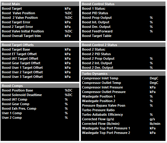
The following calculated runtimes are generated by Emtron that are Boost Control related (to be further discussed more specifically):
Boost Control Function Setup
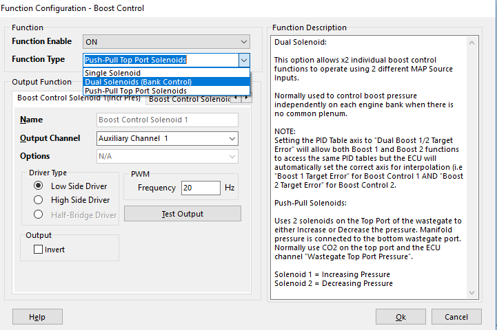
Emtron has three methods of Boost Control
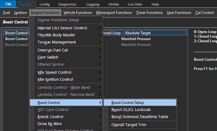
Config > Function Setup > Engine Functions > Boost Control
Single Solenoid
Control of a single solenoid.
Duel Solenoids (Bank Control)
Control of dual solenoids in Bank Configuration.
This option allows 2 individual boost control functions to operate using 2 different MAP Source Inputs.
Normally used to control boost pressure independently on each engine bank when there is no common plenum.
Setting the PID Table axis to “Dual Boost 1/2 Target Error” will allow both Boost 1 and Boost 2 functions to access the same PID tables but the ECU will automatically set the correct axis for interpolation (i.e “Boost 1 Target Error” for Boost Control 1 and “Boost 2 Target Error” for Boost Control 2).
Push-Pull Top Port Solenoids
Uses 2 solenoids on the Top Port of the wastegate to either Increase or Decrease the pressure. Manifold pressure is connected to the bottom wastegate port.
Normally use CO2 on the top port and the ECU channel “Wastegate Top Port Pressure”.
- Solenoid 1 = Increasing Pressure
- Solenoid 2 = Decreasing Pressure
Some solenoids are sensitive to flywheel diodes on ECU outputs regarding Boost Control and must be matched appropriate.
- Standard MAC valve Aux Output – Aux 1-16 – Low Side
- AMS/Bullet type valve – Spare Fuel/Ignition channel – Low Side
Valves that need to be ran at higher frequency, or in the case of Push-Pull functionality, where the valves must not float - require non-flyweel controlled outputs (Fuel/Ignition channels) to ensure the control function is appropriate.
See KV Series Hardware Manual section 3.52
Boost Control Setup
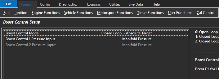
Boost Control Mode
Used to select either Open or Closed Loop.
Open Loop mode is generally used to setup initial settings before using Closed Loop mode.
- 0: Open Loop
- 1: Closed Loop – Absolute Target
- 2: Closed Loop – Gauge Target
Mode 2 works with “0” Manifold Pressure Input only. The ECU generates a channel Manifold Gauge Pressure. Manifold Gauge Pressure is derived from the Barometric Pressure Channel. Barometric Pressure Channel must be configured.
Examples
Absolute Mode
Target = 250kPa. The ECU will Target an Absolute pressure of 250kPa. Boost Pressure inside the engine will increase as Barometric pressure reduces.
Barometric Pressure of 100kPa. Boost pressure inside the engine will be 150kPa.
Barometric Pressure of 80kPa. Boost pressure inside the engine will be 170kPa. (250kPa - 80kPa)
Gauge Mode.
Target = 150kPa. The ECU will Target a boost pressure of 150kPa above Barometric pressure.
Barometric Pressure of 100kPa. ECU Boost Target will be 250kPa, boost pressure inside the engine will be 150kPa.
Barometric Pressure of 80kPa. ECU Boost Target will be 230kPa, boost pressure inside the engine will be 150kPa
Boost Target Tables are used in Closed Loop mode.
Note – Push/Pull Solenoid Mode: Open Loop mode is not available as Closed Loop functionality is required to continuously regulate the target pressure.
Boost Control 1/2 Pressure Input
Allows the Boost Control PID Input/Setpoint to be controlled.
The input for the boost target to be used in closed loop.
- 0: Manifold Pressure
- 1: Manifold Pressure - Bank 1
- 2: Manifold Pressure - Bank 2
- 3: Manifold Pressure Bank 1/2 Avg
- 4: Boost Pressure - Bank 1
- 5: Boost Pressure - Bank 2
- 6: Boost Pressure Bank 1/2 Avg
- 7: Wastegate Top Port Pressure 1
- 8: Wastegate Top Port Pressure 2
- 9: Boost Pressure
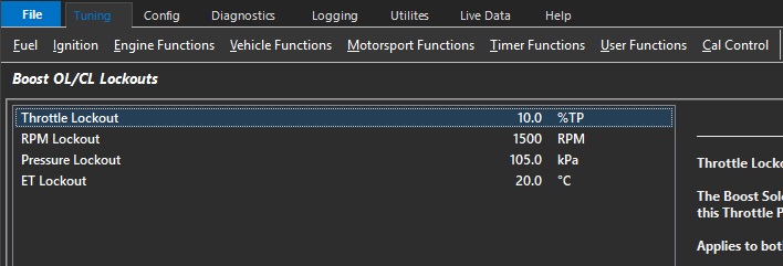
Boost OL/CL Lockouts
 \
\
Throttle Lockout
The Boost Solenoid will switch OFF below this Throttle Position
Applies to both Open and Closed Loop modes
Typical: 10.0% ( 0 = OFF)\
RPM Lockout
The Boost Solenoid will switch OFF below this RPM.
Applies to both Open and Closed Loop modes
Typical : 1200 RPM ( 0 = OFF)
Pressure Lockout
The Boost Solenoid will switch OFF below this pressure
Applies to both Open and Closed Loop modes
Open Loop: ECU uses “Manifold Pressure” runtime
Closed Loop: ECU uses the pressure channel selected in the PID Setup Menu -> Boost 1 PID Input Source
Typical : 110 kPa ( 0 = OFF)
ET Lockout
The Boost Solenoid will switch OFF below this Engine Temperature
Applies to both Open and Closed Loop modes
Typical : 10.0 °C ( -50.0 = OFF)
Boost Solenoid Deadtime Table (ms)
This look up table defines the deadtime of the Boost Solenoid.
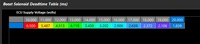
The deadtime of the solenoid is crucial where control of the boost solenoid duty cycle is especially crucial – IE applications using Push-Pull solenoids or 4-port solenoid control.
Note: Deadtime will automatically add Boost Valve Position %.
A good way to set solenoid deadtime is to do it on a bench and monitor leakage through the valve. Increase deadtime until the brink of leakage, and deadtime is correct.
Boost Target Tables
Used by the ECU to determine the base Boost Pressure Target
Boost Control Target can be selected as Absolute or Gauge. NOTE: The ECU will always generate the final Boost Target as Absolute value.
Absolute Mode. This is the Target Boost Pressure independent of Barometric Pressure.
Gauge Mode. This is the Target Boost Pressure above Barometric Pressure
Example.
Absolute Mode. Target = 250kPa. The ECU will Target an Absolute pressure of 250kPa. Boost Pressure inside the engine will increase as Barometric pressure reduces.
Barometric Pressure of 100kPa. Boost pressure inside the engine will be 150kPa.
Barometric Pressure of 80kPa. Boost pressure inside the engine will be 170kPa. (250kPa - 80kPa)
Gauge Mode. Target = 150kPa. The ECU will Target a boost pressure of 150kPa above Barometric pressure.
Barometric Pressure of 100kPa. ECU Boost Target will be 250kPa, boost pressure inside the engine will be 150kPa.
Barometric Pressure of 80kPa. ECU Boost Target will be 230kPa, boost pressure inside the engine will be 150kPa
Boost Target Table 1/2/3
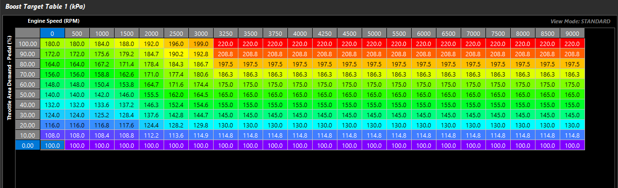
3 tables are available depending on CAL slot control or Boost Table Control
Table are active when closed loop boost control are active
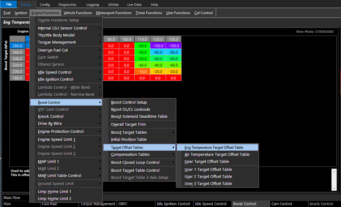
Offset Target Tables
Allows the user to define a target change to the Boost Target during the specified functions:
These tables can be expanded into a 3D look up table using any runtime for the axis.
Target Offsets are specific tables and 3 additional user definable tables.
Boost Target Clamp Table
Clamps the final Boost Target.
0 kPa or 500.0 kPa= OFF.
Boost Target Table Control
Selects the active control method of the Boost Target Table
- 0: Not Available
- 1: ON - Target Table 1
- 2: ON - Target Table 2
- 3: ON - Target Table 3
- 4: Not Available
- 5: Cal Slot
- 6: ON - Z-Axis
Boost Target Table Z-Axis Setup
When using Mode 6 in Boost Target Table Control, Boost Target Table Z-Axis Setup becomes available
Blend through the 3 different Boost Target Tables using Emtron available Runtimes.
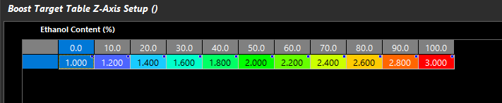
- 1.000 = Table 1
- 2.000 = Table 2
- 3.000 = Table 3
- 1.750 = 75% of the way between Table 1 and Table 2.
Initial Position Table
Used by the ECU as the main feed forward value to determine the output duty cycle.
This table is used in Open Loop Mode
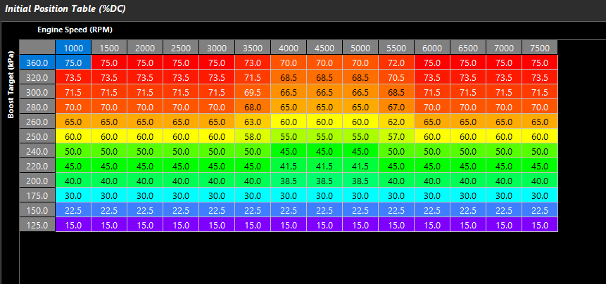
Initial position is the feed forward for Boost Valve Position %, and the closed loop PID if CL is active.
Boost Valve Deadtime is pre-calculated and added to Initial Position.
Push/Pull Solenoid Control will require no/very little initial position.
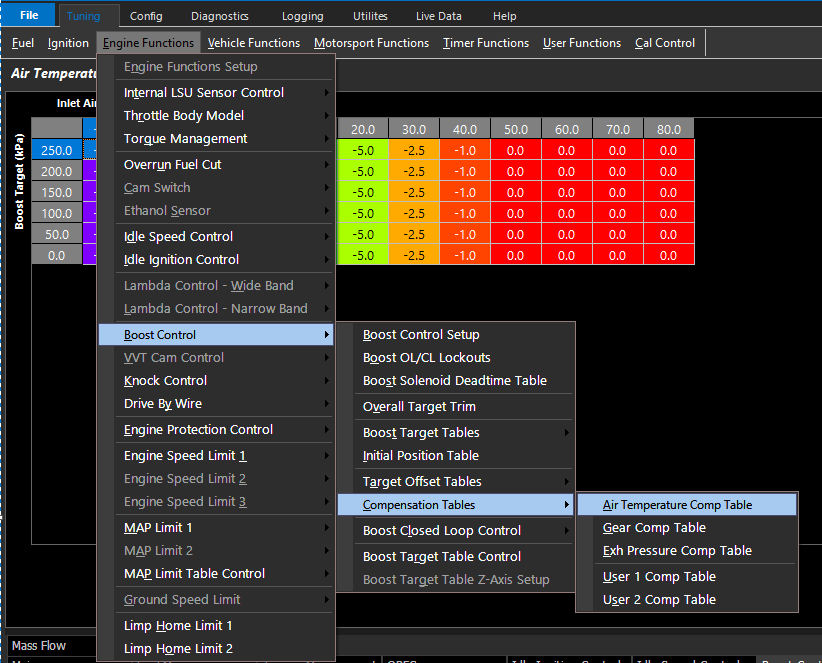
Compensation Tables
Offset change to the Initial Position table (Duty Cycle %) during the specified functions:
These tables can be expanded into a 3D look up table using any runtime for the axis.
Boost Closed Loop Control
For 4 Port Solenoid and Push-Pull Top Port Solenoid Control, it is advised to use much smaller gains to start.
Control Rate
The rate at which the PID control algorithm calculations are performed.
Typical : 25 Hz
Boost Deadband +/-
The output control signal is held constant when the Input Signal (normally MAP) falls within the deadband range of the Setpoint (Boost Target). This helps reduce steady state error and oscillations.
Typical : 2 kPa
Input Filter
Filters the Input signal to help smooth out any pulsations
Note: Input Signal usually MAP.
Typical Value: 5 ( 0 = OFF)
Target Filter
Filters the Target signal to help smooth out any pulsations
Typcial Value: 4 ( 0 = OFF)
Pos/Neg Integral Limit Tables
The minimum or maximum Integral Gain the Boost Control system can apply
Min/Max Duty Tables
The minimum or maximum duty cycle the Boost Control system can apply