Subsections of Cam Control
VVT Cam Control
VVT Cam Control Setup
All Emtron ECU’s can support variable camshaft position control (VVT – Variable Valve Timing). Up to 4 Cam Control channels can be configured depending on the ECU model (two intake, two exhaust).
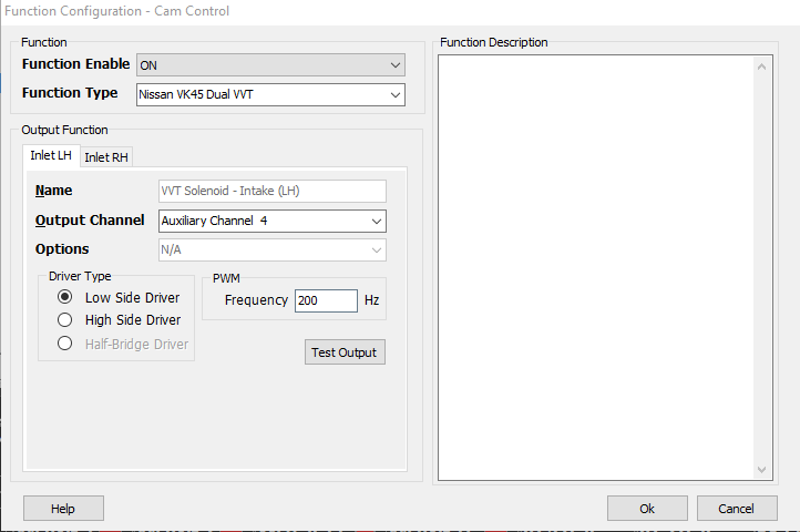
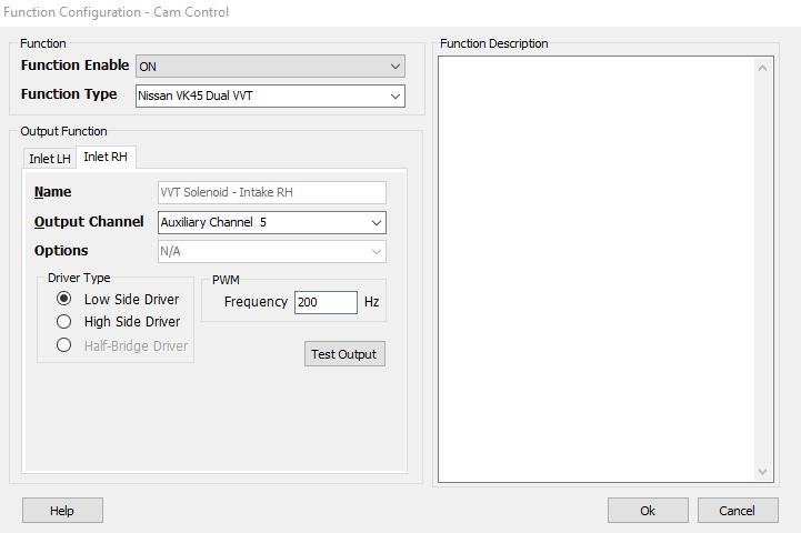
Select the control system and appropriate outputs:
Config View -> Function Setup -> Engine Functions -> Cam Control
OFF = Function is switched off and the selected output channels are deallocated.
ON = Function is switched on.
Function Type
Choose the supported VVT system from the list.
Output Channel Selection
All Emtron outputs can be configured for Cam Control, however standard Aux Channels should be prioritized for this. Most of Emtron Aux Channels are flexible in regards to output polarity as well (dependant on VVT system being used. All Cam Control systems used closed loop position control - see Cam Switch for open loop control)
- Sl4/SL8 - Aux 1 – 8 Low side, Aux 5 – 8 High side, Aux 9 – 10 Half bridge
- KVx Rev 1 - Aux 1 – 8 Low/High side, Aux 9 – 12 Half bridge, Aux 13 – 16 Low side
- KV8 Rev 2 - Aux 1 – 8, 13 - 16 Low/High side, Aux 9 – 12 Half bridge
- KV12 Rev 2 - Aux 1 – 8 Low/High side, Aux 9 – 16 Half bridge
- KV16 Rev 2 - Aux 1 – 8 Low/High side, Aux 9 – 16 Half bridge
Spare fuel and ignition channels are Low side. Prioritize VVT channels to Aux channels.
Channel selection is as follows:
- Inlet LH - Bank 1 intake camshaft
- Exhaust LH - Bank 1 exhaust camshaft
- Inlet RH - Bank 2 intake camshaft
- Exhaust RH - Bank 2 exhaust camshaft
Driver Type
Select either Low side, or High side depending on the VVT system being used.
See engine wiring schematic. VVT solenoids are normally supplied with constant 12V+ or ground (use opposite control polarity).
BMW VANOS
BMW VANOS Support
Early BMW Motorsport VANOS systems were unique. It uses an auxiliary oil pump that boosts operating oil pressure to a constantly regulated 100bar of pressure. The high pressure is used to hydraulically lock the cam position to target during all operating conditions. The design of the system requires two channels per camshaft as there is no default position (ie – Intake retarded position, exhaust advanced position). This means there are separate channels for each camshaft for retard and advance. If the control system is at target, the cams remained hydraulically locked by switching the control system off. Because of the unique mechanical nature of the system, ECU control must be very specific. Emtron has developed a special strategy that mimics the OE function, but allows complete flexibility to enable even more precise control.
BMW Engines that use high pressure BMW Motorsport VANOS
- BMW S50B30 - Single VANOS intake cam
- BMW S50B32 - Double VANOS intake and exhaust cam
- BMW S54 - Double VANOS intake and exhaust cam
- BMW S62 - Double VANOS intake and exhaust cam (two banks)
USA versions BMW S50B30 (and BMW S52B32) do NOT use BMW Motorsport VANOS.
Later Motorsport models updated VANOS to more conventional control. BMW S65 and BMW S85 use only one output per camshaft like conventional systems.
When selecting these function types, there will be additional options available for choosing the specific channels for retard or advance channels.
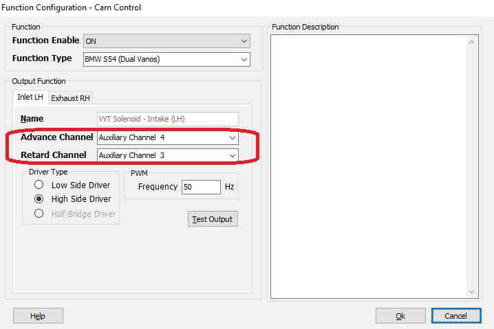
BMW Motorsport VANOS is driven high side. If the installer chooses to drive low side, the solenoids MUST be modified as the flyback diodes will now allow them to be driven low. Diodes must be reversed or removed.
Cam Control - PID
PID Setup
Applicable to both intake & exhaust PID setup
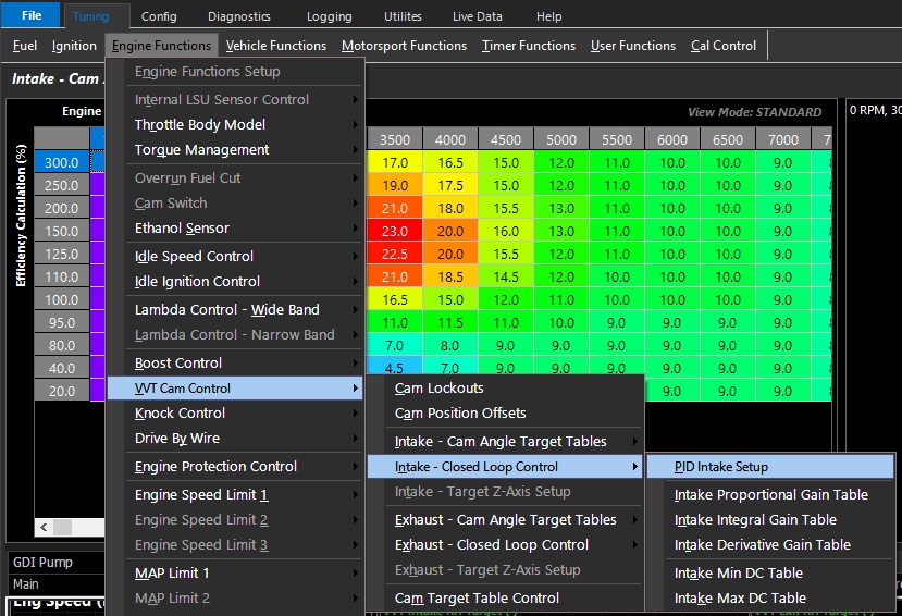
The positioning control of the Camshaft(s) is governed by the Emtron PID closed loop function.
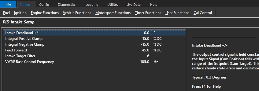
Intake Deadband +/-
The output control signal is held constant when the Input Signal (Cam Position) falls within the deadband range of the Target.
This helps reduce steady state error and oscillations.
**BMW Motorsport VANOS systems switches off the control signal automatically when in deadband to hydraulically lock the cam position.
Typical : 0.5 degrees
Integral Positive Clamp
Allows the user to set the the maximum Integral gain compensation used by the closed loop system.
Integral Negative Clamp
Allows the user to set the minimum Integral gain compensation used by the closed loop system
Feed Forward
Having a correct feed forward duty cycle value allows for more precise control.
This feed forward value is added to the control signal before the PID is applied.

Tuning Tip:
This is the expected duty cycle of the solenoid to hold the camshaft in a given position.
It can be quickly determined by commanding the camshaft to a position & witnessing the required duty to do so.
Commanding an alternative angle will deliver a similar result, the average of these is your feed forward value.
Intake Target Filter
Filters the Target signal to help smooth out any pulsations.
Typical Value: 5 ( 0 = OFF)
VVTiE Base Control Frequency
Toyota 2URFSE/2URGSE VVTiE Base frequency setting at 1000rpm
For PID Exhaust setup
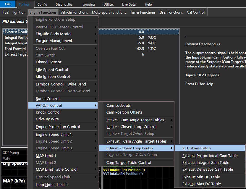
Cam Lockouts
CAM Lockouts
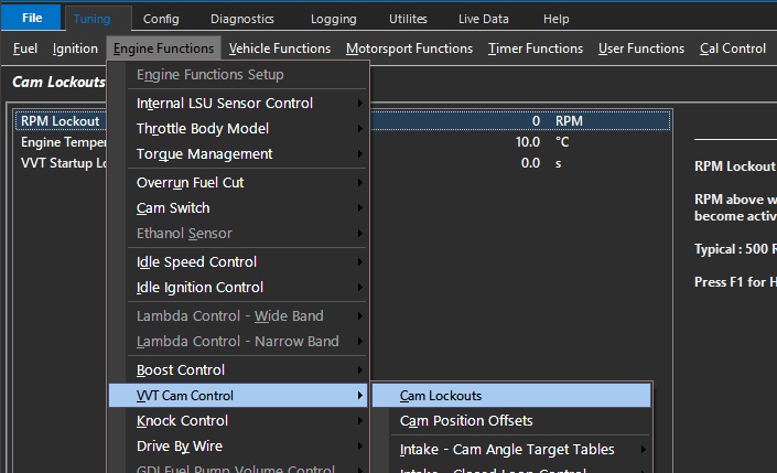
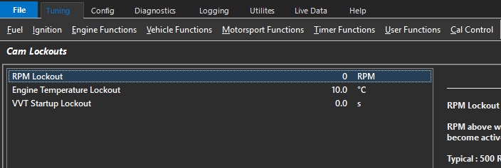
RPM Lockout
RPM Lockout
Engine speed above which Cam Control is set to become active
Typical : 500 RPM
Engine Temp Lockout
Engine Temp above which Cam Control is set to become active.
Typical : 60 degC
VVT Startup Lockout
Delay timer from Crank RPM Exit before VVT Cam Control is permitted to become active.
This setting helps prevent the Cam Control Solenoid “Rattling” at startup due to low oil pressure.
Typical : 500 RPM
Cam Position Offsets
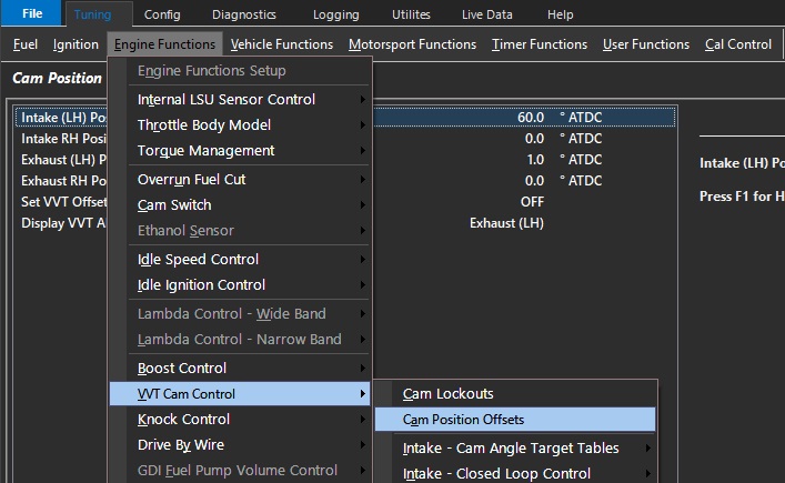
Like Crank Position Offset, the ECU must know the offset position of each Camshaft used for Cam Control as well.
The offset allows the target look up table to either add or subtract desired position based on this entry.
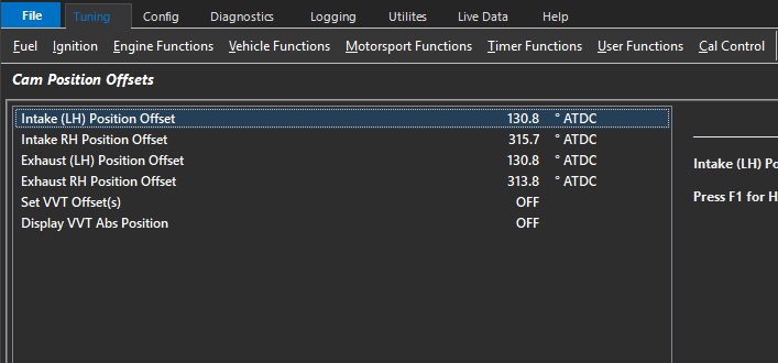
To program the Position Offset, the ECU must put the engine into a special mode to return the camshafts to default positions (intake retarded, exhaust advanced).
Generally, this forces the ECU to stop attempting to regulate the camshafts (VVT solenoids OFF).
There are 2 methods to achieve the same goal.
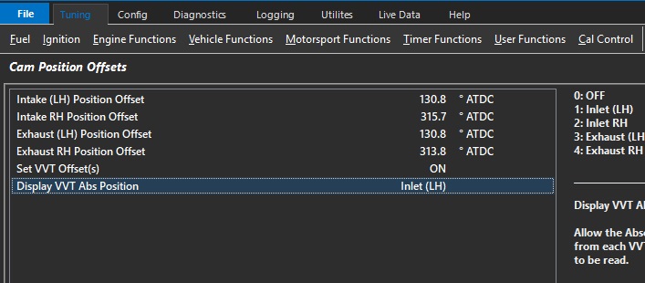
Method 1
Start engine (warm engine)
Set VVT Offset(s) = 1 (ON)
Display VVT Abs Position = choose camshaft to display
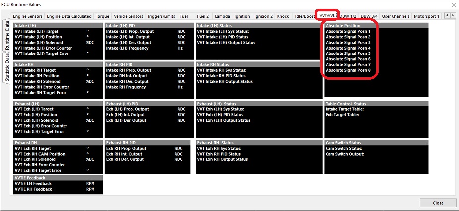
Under Runtimes (F3, VVT/VVL)
Use absolute position runtimes to populate the offset.
Each position represents either a rising or falling edge per cycle (dependent on edge selection under inputs). Choose the lowest number.
Method 2
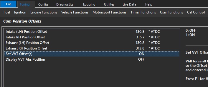
Whilst on the Cam Position Offset page
Start engine (warm engine)
Set VVT Offset(s) = 1 (ON)
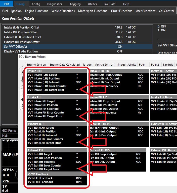
Open ECU Runtimes (F3) go to VVT/VVL
Use the VVT target Error to validate the position offset number.
This can be do by simply increasing or decreasing the value until as close to zero error is achieved.
Once completed for each cam, set VVT Offset(s) to = 0 (Off)
BMW VANOS Support
Because BMW Motorsport VANOS systems to not return to default positions when the VVT solenoids are OFF, Emtron has a specialized function that will automatically apply a constant duty to the intake retard channels and exhaust advance channels when the Set VVT Offset(s) mode = 1. This allows the user to program the Position Offsets for each camshaft as normal.
Cam Switch
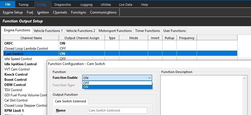
The Emtron ECU Cam Switch function is a comprehensive function to control simple cam switch solenoids
(VTEC, Lift solenoids, advance/retard solenoids).
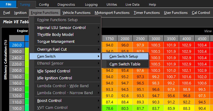
Instead of just having standard switch criteria like a simple RPM or load threshold, the Emtron Cam Switch function has a series of setup functions, plus a 3D table to control its activation.
The 3D table should not be mistaken for a PWM duty table – This is not a closed loop control system.
For PWM duty control, use the VVT Cam Control function.
Output Setup
Output Channel Selection
Select open outputs that are appropriate for the type of Cam Switch system you are using
Driver Type
Set Low or High side function
Frequency
There should be no frequency/PWM function enabled for this function. It is a “switch” function only.
Function Setup
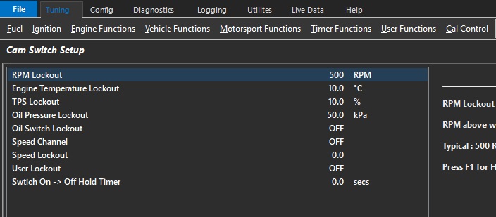
RPM Lockout
RPM above when the Cam Switch can become active. Typically 500rpm.,
Engine Temp Lockout
Temperature above when the Cam Switch can become active. Typically 20 DegC
TP Lockout
Throttle above when the Cam Switch can become active. Typically 10.0%
Oil Pressure Lockout
Oil Pressure above when the Cam Switch can become active. Only applies if Oil Pressure Input Channel has been configured.
Oil Switch Lockout
Used to ensure there is oil pressure when the Cam Switch can become active. Only applies if Oil Pressure Switch Input Channel has been configured.
Speed Channel
Select Speed Channel to be used for Speed Lockout (below)
Speed Lockout
Speed above when the Cam Switch can become active. Typically 5kph.
User Lockout
Allows the Cam Switch function to be locked out by a user function. When the User Function is ON, the lockout is active.
Switch ON -> OFF Hold Timer
When the Output has been commanded to switch OFF, this setting will keep the Output ON for the time entered. Useful for example by allowing the Output to remain ON during gearshift.
Cam Switch Table
This look-up table commands the ECU to switch the Cam Switch Output OFF, ON, or remain unchanged.
Value 0 = Cam Switch OFF
Value 100 = Cam Switch ON
Any number in between 1-99 is hysteresis mode which causes the output to remain unchanged. Typical value used is 50. This prevents the Cam Switch function output toggling ON/OFF when the mapped point is close to the edge of activation.
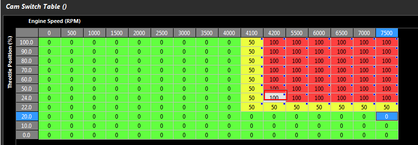
The above picture illustrates an example of how to implement hysteresis in a CAM Switch Table.
RPM Axis. Between 4001 and 4199 there is no output change defined by a Table value of 50. With increasing RPM at 4200 the output will Switch ON defined by a Table value of 100. With Decreasing RPM at 4000 the Output will Switch OFF defined by a Table value of 0. The result is a Hysteresis of 200 RPM
Throttle Position. Between 20.1% and 23.9% there is no output change defined by a Table value of 50. With increasing Throttle at 24.0% the output will Switch ON defined by a Table value of 100. With decreasing Throttle at 20.0% the Output will Switch OFF defined by a Table value of 0. The result is a Hysteresis of 4% Throttle.
Exhaust Cam Angle Target Tables
Exhaust Cam Angle Target Tables
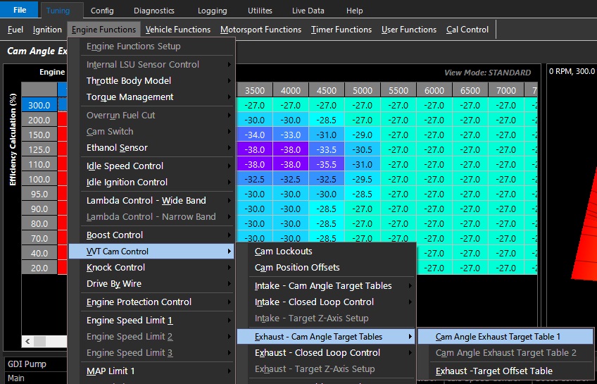
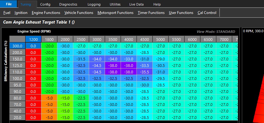
This is the Exhaust camshaft position command tables where the required camshaft position in degrees is set
Table units start from 0.
Negative numbers represent targeting retarded position of the camshaft.
Exhaust target map = -20 degrees = 20 degrees of exhaust cam retard
**Typically numbers close to 0 represent the least amount of overlap which helps with idling.
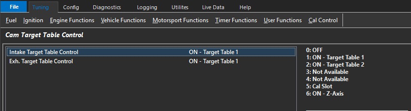
Exhaust Cam Angle Target Table 2 can be accessed/activated via Cam Target Table Control
There are a variety of methods of integration available.
WARNING
Incorrect setting of the Exhaust Cam Angle Target Table can result in engine damage.
In modified engines, the piston to valve clearance of the engine should be measured.
The maximum safe advance angle should be known prior to setting VVT travel range.
If the valve clearance is compromised within the available travel range a mechanical limit should be employed to prevent contact.
DO NOT rely on closed loop Cam Control to prevent piston to valve contact when there is a mechanical ability to cause contact.
BMW Motorsport VANOS should not be targeted to the fully retarded or advanced position at any point.
This is because the system is designed to hydraulically lock the position once at the target (no solenoid regulation).
If for whatever reason the offset position is not exact (some variance with temp, engine speed, etc), the system could potentially over-regulate the solenoids.
Targeting a few degrees before each end stop is typical and mimics the OE function.
Intake Cam Angle Target Tables
Intake Cam Angle Target Tables
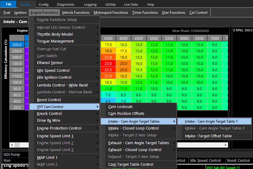
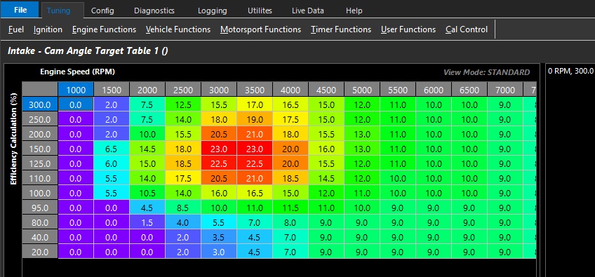
This is the Intake camshaft position command tables where the required camshaft position in degrees is set
Table units start from 0.
Positive numbers represent targeting advanced position of the camshaft.
Intake target map = +25 degrees = 25 degrees of intake cam advance
**Typically numbers close to 0 represent the least amount of overlap which helps with idling.
Intake Cam Angle Target Table 2 can be accessed/activated via Cam Target Table Control
There are a variety of methods of integration available.
WARNING
Incorrect setting of the Intake Cam Angle Target Table can result in engine damage.
In modified engines, the piston to valve clearance of the engine should be measured.
The maximum safe advance angle should be known prior to setting VVT travel range.
If the valve clearance is compromised within the available travel range a mechanical limit should be employed to prevent contact.
DO NOT rely on closed loop Cam Control to prevent piston to valve contact when there is a mechanical ability to cause contact.
BMW Motorsport VANOS should not be targeted to the fully retarded or advanced position at any point.
This is because the system is designed to hydraulically lock the position once at the target (no solenoid regulation).
If for whatever reason the offset position is not exact (some variance with temp, engine speed, etc), the system could potentially over-regulate the solenoids.
Targeting a few degrees before each end stop is typical and mimics the OE function.
Intake/Exhaust Target Offset Tables
Intake/Exhaust Target Offset Tables
These are user defined tables are used to offset the Cam Target.
The tables operate in Absolute values (degrees).