Cruise Control
Cruise Control Application Build
1.0 Introduction
The Cruise Control Application Build is available for all Emtron ECUs. This build allows unique application-specific firmware to be installed into the ECU. The strategy involves the ECU managing engine torque (Nm) by calculating the correct throttle area for the target vehicle speed. The speed error is then corrected using a PID controller.
It is important that the throttle body model is calibrated and the engine model is correctly configured. The air flow model using the throttle mass flow calculation (TMF) requires a pressure reference pre and post throttle. In naturally aspirated applications the use of barometric pressure for the pre-throttle channel will be enough to achieve reasonable results; however, it is recommended to install a pressure sensor pre-throttle. Turbocharged applications must run a pre-throttle pressure sensor. Any of the three boost pressure input channels may be used for the pre-throttle pressure.
For further information on Throttle Mass Flow (TMF), refer to the Help Topic “Throttle Mass Flow Setup” in the Emtune software for a detailed explanation on how to configure and tune this system properly. DO NOT attempt to use the Cruise Control function until TMF calibration is complete.
WarningDISCLAIMER Cruise Control is designed to assist the driver and is not a substitute for safe and attentive driving practices. Any failure to follow the directions provided in the Cruise Control Application Build is at the sole risk of the user. Not all vehicle configurations allow the use of Cruise Control due to hardware limitations. Emtron Australia will not be liable for any physical or financial injury, loss or damage arising from the improper use or improper setup of this function.
2.0 Build Setup
The Cruise Control Application Build needs to be enabled by an authorised Emtron dealer before it may be installed into the ECU. Each build is locked to an ECU serial number, then available for installation from the Emtron online server.
2.1 Installation procedure
- Internet access is required for the build installation, allowing Emtune to access the Emtron online server.
- Connect Emtune to the ECU.
- Firmware Version 2.17.0 or later should be used.
- Select the File → Build Management menu. A window will open and display all build options.
- Select the Cruise Control option which should be listed as INSTALL. Press OK.
- The installation process will take 5-10 seconds. A message box will confirm a successful installation.
- To further verify the installation and view the status of all available builds, open the Runtime menu (F3) and select the “ECU Internal” tab.
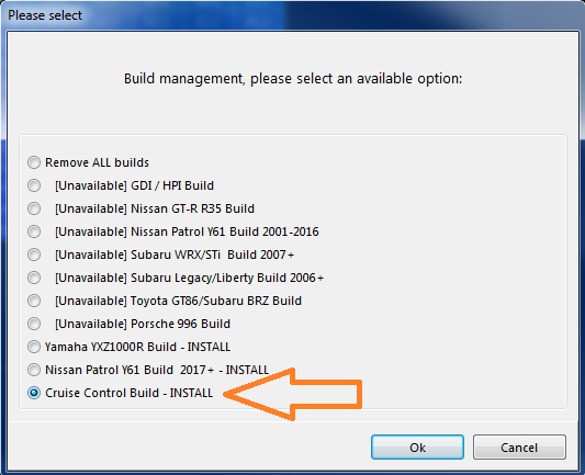
File → Build Management — install the Cruise Control build.
2.2 Uninstall procedure
If the build has been previously installed it can be uninstalled at any time. With internet access and Emtune connected, select File → Build Management, select the Cruise Control option (listed as UNINSTALL), and press OK. The uninstall process takes 5-10 seconds.
3.0 Configuration
For the function to operate correctly the following minimum requirements MUST be adhered to.
3.1 Input Switches
- Brake Switch
- Clutch Switch (Manual Transmission with mechanical clutch)
- Cruise Enable Switch
- Cruise SET/COAST Switch
- Cruise RESUME/ACCEL Switch
- Cruise CANCEL Switch
3.2 Sensors
- Speed Sensor
- Boost Pressure Sensor (pre-plate pressure sensor)
- Inlet Manifold Pressure Sensor (after-plate pressure sensor)
- Pedal Position Sensor Main
- Pedal Position Sensor Sub
- Servo Position Sensor Main
- Servo Position Sensor Sub
3.3 Hardware
- Electronic Throttle Body (DBW)
- Throttle Pedal with two (2) position sensors
3.4 Function Lockouts
The ECU constantly monitors the required channels and will lock out cruise control if one of these is not configured, in fault, or not selected.
Critical Lockouts
X-TMF1 Sensor Before Fault— Sensor in fault or not selected for DBW 1X-TMF1 Sensor After Plate Fault— Sensor in fault or not selected for DBW 1X-TMF2 Sensor Before Fault— Sensor in fault or not selected for DBW 2X-TMF2 Sensor After Plate Fault— Sensor in fault or not selected for DBW 2X-TMF Disabled— Throttle Mass Flow function is off so Cruise Control is disabledX-Cruise Enable Sw Config— The Cruise Control Enable (Off/On) switch is not configuredX-Cruise SET Sw Config— Cruise Control Set switch is not configuredX-Cruise RESUME Sw Config— Cruise Control Resume switch is not configuredX-Cruise CANCEL Sw Config— Cruise Control Cancel switch is not configuredX-Cruise No Sw Config— There are no Cruise Control switches configuredX-Speed Source Config— There is no Cruise Speed channel configuredX-Brake Input Config— There is no Brake switch configuredX-Firmware Lockout— Application build is disabled
Non-Critical Lockouts
OFF-Cruise Enable Sw, OFF-Cruise Cancel Sw, OFF-Engine Speed Zero, OFF-Ref Speed Zero, OFF-Limiting Active, OFF-Brake Switch, OFF-Neutral, OFF-Clutch Switch.
The Cruise Control Status runtime will update to indicate which condition is locking out the function.
3.5 Function Enable
Once the Cruise Control Build is enabled, the function needs to be enabled via Config → Functions → Function Output Setup → Vehicle Functions 2 → Cruise Control.
4.0 Tuning System
Calibration of the Cruise Control system is done in the Emtune Tuning View tab: Tuning → Vehicle Function → Cruise Control → Cruise Setup.
4.1 Cruise Setup
- Cruise Max Target Speed — The maximum target speed that can be set. The ECU clamps to this value.
- Cruise Resume Speed Incr Ramp Time — The time the ECU will gradually increase the speed target back to the previously “Set” speed after a lockout has been invoked, to achieve a smooth acceleration rate back to the target speed.
- Cruise Resume Speed Decr Ramp Time — The time the ECU will gradually decrease the speed target back to the previously “Set” speed after a lockout state has been cleared, to achieve a smooth transition back to the target speed.
4.2 Cruise Closed Loop Setup
The system relies on a combination of feedforward TMF torque-based latching coupled with a PID system to control the speed.
- Cruise Control Speed Channel — Any speed channel in the ECU may be used as the input channel. This is used by the speed target.
- Cruise Proportional Gain — The gain due to the instantaneous error in speed. Typical value 1.00.
- Cruise Integral Gain — The gain due to the error with respect to time. Typical value 0.010.
- Cruise Derivative Gain — The gain due to the rate of change of the error. Typical value 12.00.
- Cruise Deadband +/- — The speed range which will hold the output. Typical value 0.2 km/h.
- Cruise Maximum Torque Clamp — The maximum clamp the system can use to attain the target speed. Set to allow the system enough torque to always achieve the target. Typical value 200-300 Nm.
- Cruise Minimum Torque Clamp — The minimum clamp the system can use to attain the target speed. Usually set to ensure maximum deceleration. Typical value -100 Nm.
The system employs an error counter which is triggered when the Cruise Minimum/Maximum Torque Clamps have been hit. The larger the target error when the torque clamps are latched, the faster the error counter increments. The system shuts down once the counter reaches the pre-determined (non-user-adjustable) value.
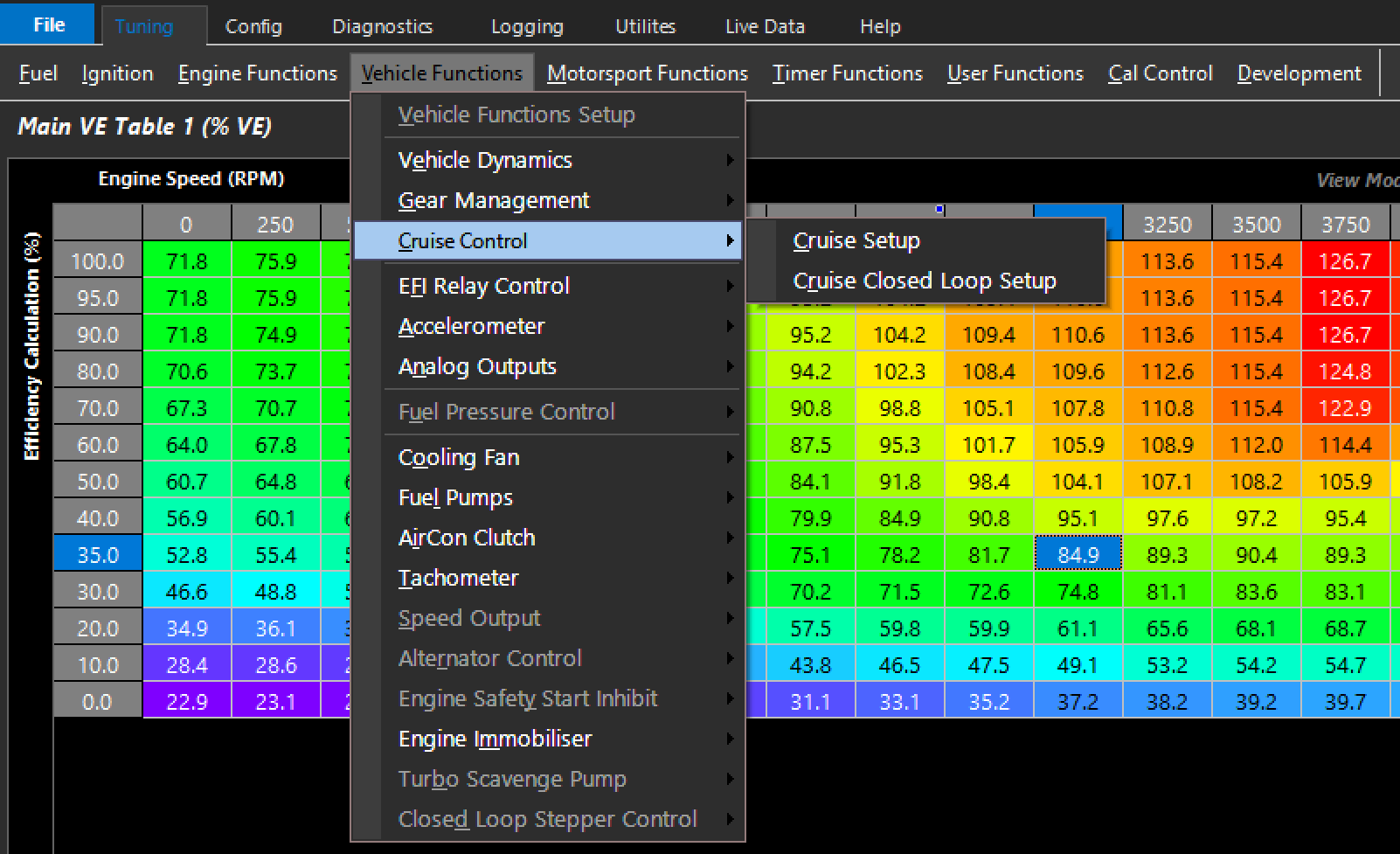
Cruise Control closed loop (PID) setup.
4.3 Runtimes
Accessed via the ECU Runtime Menu (F3): Runtime Data → Vehicle Functions → Cruise Control.
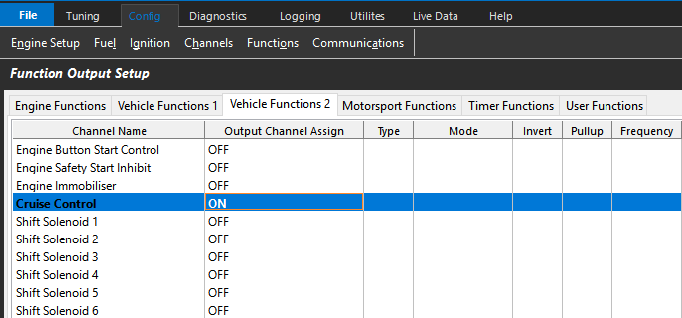
Figure 3.0 — Runtime menu, Cruise Control runtimes.
Cruise Control Status — the current system status:
- Disabled — System is OFF
- ON — System is currently active
- … Waiting SET/RESUME Sw — System is armed but in a lockout state awaiting user input to re-engage
- Starting-SET Pressed — Set has been pressed and the system will become active. The current speed is loaded as the “Speed Target”
- Restarting-RESUME Pressed — The system will resume and the last loaded Speed Target will be re-engaged
- ON – Paused Pedal — The system is active but the driver is inputting a higher throttle area demand than is being requested. Normal operation resumes after the driver input is removed. As this state is controlled by the pedal area demanded, it is important that the “Pedal to Throttle Area Translation Table” has a 0.0 setting in the “Pedal Position Demand” 0% axis.
Other runtimes: Cruise – Torque Target Base (TMF) (the TMF calculated torque value loaded as the base torque reference, converted into a throttle area demand); Cruise – Torque Target Final (TMF) (the PID-adjusted torque output using the base as feedforward); Cruise – Speed Target; Cruise – Speed Input (the actual reported speed); and the switch states Cruise RESUME Sw / SET Sw / CANCEL Sw / ON/OFF Sw (monitor these to confirm correct button assignment).
Appendix A – Bit CAN Message Information (“Cruise Control Status”)
| Bit | Status | Bit | Status |
|---|---|---|---|
| 0 | Disabled | 25 | OFF-Brake Switch |
| 1 | ON | 26 | OFF-Neutral |
| 2 | … Waiting SET/RESUME Sw | 27 | OFF-Clutch Switch |
| 3 | Starting-SET Pressed | 29 | X-TMF Disabled |
| 4 | Restarting-RESUME Pressed | 30 | X-TMF1 Sensor Before Fault |
| 5 | ON - Paused Pedal | 31 | X-TMF1 Sensor After Fault |
| 20 | OFF-Cruise Enable Sw | 32 | X-TMF2 Sensor Before Fault |
| 21 | OFF-Cruise Cancel Sw | 33 | X-TMF2 Sensor After Fault |
| 22 | OFF-Engine Speed Zero | 34 | X-Cruise Enable Sw Config |
| 23 | OFF-Ref Speed Zero | 35 | X-Cruise SET Sw Config |
| 24 | OFF-Limiting Active | 36 | X-Cruise RESUME Sw Config |
| 37 | X-Cruise CANCEL Sw Config | ||
| 38 | X-Speed Source Config | ||
| 39 | X-Brake Input Config | ||
| 40 | X-Firmware Lockout |