OFF = Function is switched off and the selected output channels are deallocated.
ON = Function is switched on
Function Type
4x DBW channels: (3 and 4 channels are only available on KV12/KV16 Serial Number > 1350)
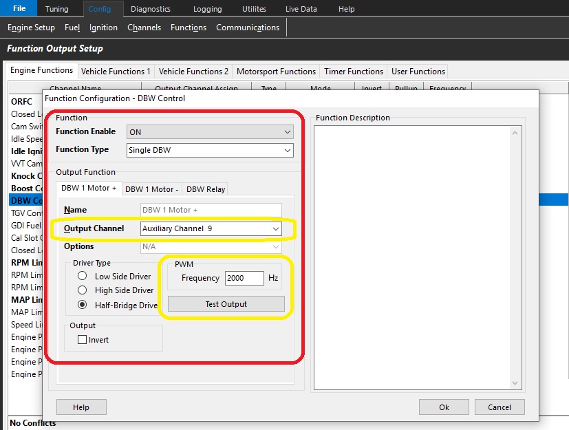
Single DBW - Using 2 Half-Bridge Drivers
Dual DBW - Using 4 Half-Bridge Drivers
3 Channel - Using 6 Half-Bridge Drivers
4 Channel - Using 8 Half-Bridge Drivers
** See graphic above – Yellow
Output Channel Selection
There are dedicated paired outputs for each DBW channel.
DBW x Motor +ve (Positive) = Auxiliary 9 - 5A Continuous 8A Limit
DBW x Motor -ve (Negative) = Auxiliary 10 - 5A Continuous 8A Limit
OR
DBW x Motor +ve (Positive) = Auxiliary 11 - 5A Continuous 8A Limit
DBW x Motor -ve (Negative) = Auxiliary 12 - 5A Continuous 8A Limit
OR KV12 and KV16 Rev2
DBW x Motor +ve (Positive) = Auxiliary 13 - 10A Continuous 20A Limit
DBW x Motor -ve (Negative) = Auxiliary 14 - 10A Continuous 20A Limit
.
OR KV12 and KV16 Rev2
DBW x Motor + (Positive) = Auxiliary 15 - 10A Continuous 20A Limit
DBW x Motor - (Negative) = Auxiliary 16 - 10A Continuous 20A Limit
** See graphic above – Yellow
NOTE: DBW +ve (Positive) and DBW – ve (Negative) polarity is defined as fully opening the throttle plate when +12V and Ground is respectively applied to these pins.
Driver Type
Select “Half-Bridge Driver” in both the “DBW Motor +” and “DBW Motor – " tabs.
Frequency
In most situations select 2000Hz. A range of 500Hz to 10kHz is available.
NOTE: Select the same frequency in both the DBW Motor + and DBW Motor – tabs for each respective motor.
DBW Relay
This relay will supply +12V to the ECU pin “Aux9-12 " (and/or Aux13-16) which will power the Half-Bridge drivers used to control the DBW Motor.
For safety reasons the DBW system will not operate until an Output Channel has been assigned.
When the ECU detects one of the following system errors the DBW relay will be switched off, shutting the DBW system down.
Target Tracking Error
Servo Position Tracking Error
Input Servo Position Channels
For safety reasons, there are redundant inputs for pedal position and drive by wire servo position. Once the sensors are setup and calibrated, these positions are used to define the DBW target in closed loop.
There are pre-configured functions to help quickly calibrate the pedal position sensors, and throttle position sensors. See
Each DBW Channel has 2 dedicated inputs for Position Feedback. These are:
DBW 1 Channel Position Feedback
DBW 1 Servo Position Main = Analog Volt 1 - 16
DBW 1 Servo Position Sub = Analog Volt 1 – 16
*Or Maximum ANV channel count depending on ECU model
DBW 2 Channel Position Feedback
DBW 2 Servo Position Main = Analog Volt 1 - 16
DBW 2 Servo Position Sub = Analog Volt 1 – 16
DBW 3 Channel Position Feedback
DBW 3 Servo Position Main = Analog Volt 1 - 16
DBW 3 Servo Position Sub = Analog Volt 1 – 16
DBW 4 Channel Position Feedback
DBW 4 Servo Position Main = Analog Volt 1 - 16
DBW 4 Servo Position Sub = Analog Volt 1 – 16
Input Pedal Position Channels
Pedal Position 1 = Analog Volt 1 - 16
Pedal Position 2 = Analog Volt 1 - 16
Sensor Calibration
The positioning sensors for the system must be calibrated like any other sensor. This can be done manually using the Calibration Table or there is an auto calibrate function described below.
Auto Calibration of Pedal Sensors
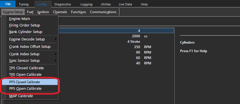
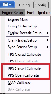
See the following menu: Config View -> Engine Setup -> PPS closed and PPS open calibrate.
Throttle Position Input Channel
The Throttle Position Input channel is NOT required in DBW applications as the DBW uses Servo Positions Inputs; the Throttle Position Input channel can be switch OFF.
The ECU will automatically copy the DBW 1 Servo Position Main into the Throttle Position 1 runtime.
This will allow functions requiring this input (gauges, logging, ORFC, Lockouts) to continue working.
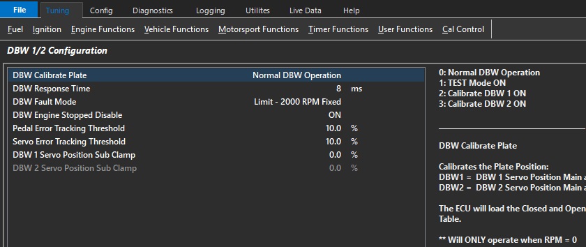
DBW 1/2 Configuration
DBW 1/2 Configuration
DBW Calibrate Plate
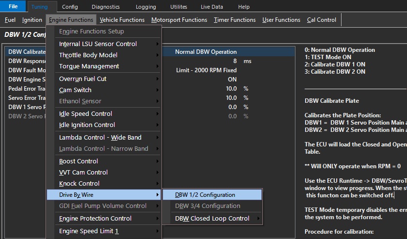
See the following menu: Tuning View-> Engine Functions -> Drive By Wire -> DBW 1/2 (or 3/4) Configuration
The following options are available:
0: Normal DBW Operation
1: TEST Mode ON
2: Calibrate DBW 1 ON
3: Calibrate DBW 2 ON
Modes 2 and 3 will calibrate the Plate Position (Servo Position):
The auto calibrate procedure populates the sensor calibration tables under input channels automatically for both fully closed and fully open positions.
NOTE:
** Will ONLY operate when RPM = 0
** TEST Mode temporarily disables the error checking allow final checks on the system to be performed
** Under no conditions should the vehicle be driven with the DBW system in TEST Mode.
** Calibrate Plate will not be possible where the Servo Position (Sub) reading clamps before complete blade deflection – Manual calibration will be required in this case.
Procedure for calibration:
Select which plate you need to calibrate (DBW1/2, or DBW 3/4)
Input pins for DBW Servo Positions must be enabled and setup correctly.
The ECU will move the throttle plate and calibrate the open and closed positions.
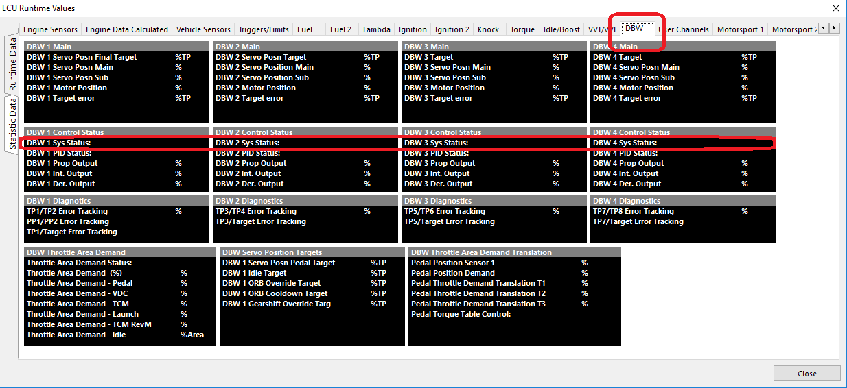
Use the ECU Runtime (F3) -> DBW/Sevro Tab -> DBW 1/2/3/4 - System Status window to view progress.
When the status reads “Calibrate Complete” , the DBW Calibrate Plate setting to can switched to “TEST Mode ON”.
This allows PID plate control but disables ALL tracking and safety features allowing PID calibration.
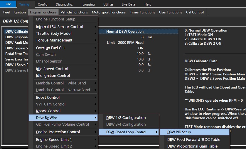
For PID control see Tuning View-> Engine Functions -> Drive By Wire -> DBW Closed Loop Control
Once the PID has been calibrated and the DBW Servo Position inputs are tracking correctly the TEST mode can be disabled.
Select DBW 1/2 Plate Calibration back to Normal mode.
DBW Response Time
The response time is the time from a commanded input change to the output changing.
Typical Time: 8 -12ms
DBW Fault mode
Emtron has an added layer of protection regarding a DBW fault (Servo position tracking, Target error, etc). The user can further define the engine behavior here.
DBW Fault Mode
0: Limit - 2000 RPM Fixed
1: Limp Home Table 1
2: Limp Home Table 2
In the case of a mechanically blocked throttle plate for example, even if the DBW system power supply is shut down, the engine could still run away.
This extra layer of protection allows the ECU to limit the engine RPM as well.
This makes a DBW system used with the Emtron product safer than even a cable operated system in regards to mechanical situation where a throttle is physically blocked open.Throttle Position Input Channel
The Throttle Position Input channel is NOT required in DBW applications as the DBW uses Servo Positions Inputs; the Throttle Position Input channel can be switch OFF.
The ECU will automatically copy the DBW 1 Servo Position Main into the Throttle Position 1 runtime. This will allow functions requiring this input (gauges, logging, ORFC, Lockouts) to continue working.
DBW Engine Stopped Disable
When the engine is stopped (RPM = 0 ) and Pedal Position is < 0.5% the DBW system can be disabled.
(Prevents battery drain with prolonged key-on use)
As soon as a Crank Signal is detected or the pedal moves > 0.5% the system becomes active again.
Pedal Error Tracking Threshold
When the difference between Pedal Position 1 and 2 is greater than the threshold, the ECU determines this to be an error condition and and increments a Error Counter.
The greater the difference, the faster the counter increments.
DBW Shutdown condition occurs when Error Counter reaches 100.
Typical 5.0%
Since the pedal position is validated by redundant inputs, once calibrated the position values can be compared and ultimately shutdown the DBW system if a sensor is failing.
The threshold here can be adjusted for the minimum amount of error needed for Error Tracking to start counting.
NOTE"
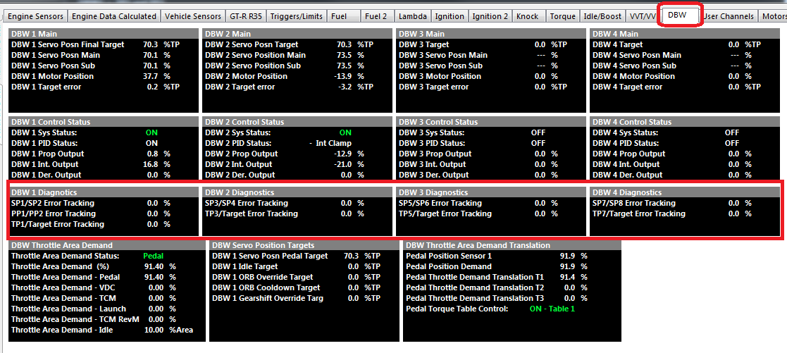
** Once “Error Tracking” for Pedal Position (PP) or Servo Position (SP) reaches 100%, the DBW system will be shut down and remain shutdown until the ECU power is cycled.
The Error Tracking rate is proportional to error so the bigger the error the faster the counter increments .
Servo Error Tracking Threshold
When the difference between DBW Servo Position Main and Sub is greater than the threshold, the ECU determines this to be an error condition and and increments a Error Counter.
The greater the difference, the faster the counter increments.
DBW Shutdown condition occurs when Error Counter reaches 100.
Typical 5.0%
DBW 1 Servo Position Sub Clamp
Used in applications when the DBW 1 Servo Position Sub signal does not span the full movement of the throttle plate.
Enter in the maximum %Servo Position as seen when the plate is fully open.
Typical applications include the Ford BA/BF/FG where this value is 51.0%
In normally applications set to 100% or
0 = OFF
DBW 2 Servo Position Sub Clamp
Used in applications when the DBW 2 Servo Position Sub signal does not span the full movement of the throttle plate.
Enter in the maximum %Servo Position as seen when the plate is fully open.
Typical applications include the Ford BA/BF/FG where this value is 51.0%
In normally applications set to 100% or
0 = OFF
DBW Calibration Guide
Steps to Calibrating and Tuning DBW
Set up Output and Input configuration functions for your ECU type as instructed here -> Drive by Wire (DBW)
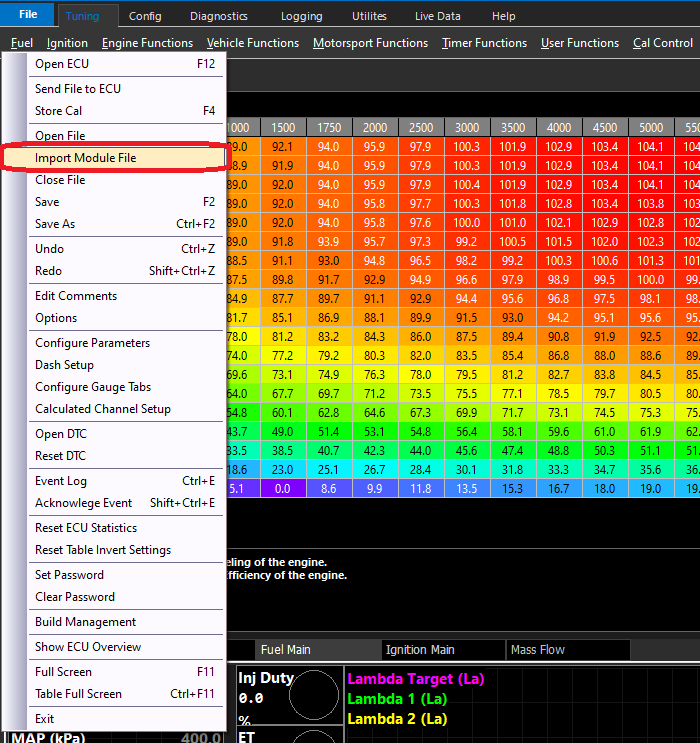
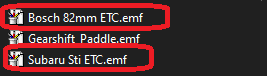
Once Inputs and Outputs are set up, select a “Module File” that is closest to your throttle system
This will pre-populate all basic settings for DBW throttle PID, response time, delay, etc.
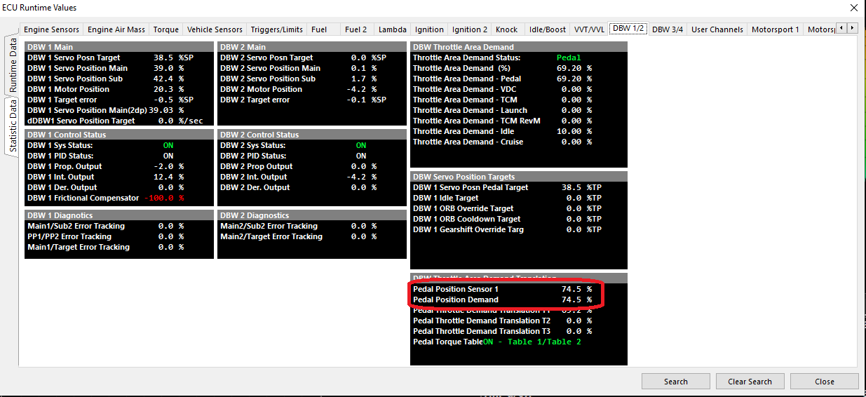
Validate the Pedal is channels are tracking correctly in Runtimes (F3)
Calibrate DBW positions using Auto Calibrate Procedure, See “DBW Calibrate Plate” here -> DBW 1/2 Configuration
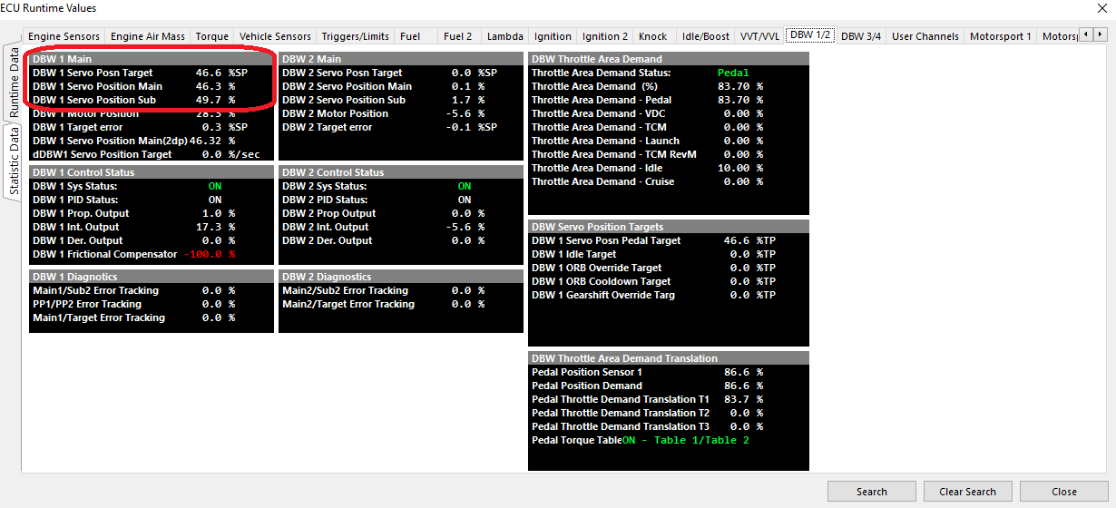
Validate the DBW Servo Position channels are tracking correctly in Runtimes (F3)
Adjust PID to suit the throttle if is not moving/tracking appropriately -> DBW Closed Loop tables
DBW Closed Loop Control - DBW PID Setup
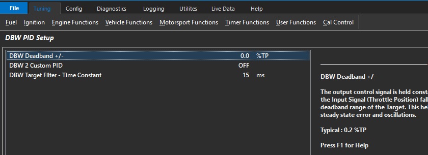
DBW PID Setup
DBW Deadband +/-
The output control signal is held constant when the Input Signal (Throttle Position) falls within the deadband range of the Target.
This helps reduce steady state error and oscillations.
Typical : 0.2 %TP
DBW 2 Custom PID
If a second DBW servo is used that is of a different type, then the PID can be customized separately.
This enables configuration tables for DBW 2
** Most commonly used when a DBW servo is used for bypassing air for a turbocharged or supercharged vehicle (DBW Air Bleed)
0: OFF
1: ON
DBW Target Filter - Time Constant
Low pass digital filter Time Constant characterizes the speed taken to respond to a step input.
The value entered represents the time (in ms) it takes for the output to reach 63% of the stepped input value.
For example if the step input changed occurred from 0 - 50.0% and the Time Constant was 25ms, the filtered output would reach 31.5% after 25ms.
Tuning DBW PID
DBW servo position is controlled in the Torque Management section -> Pedal Demand.
See Torque Management – Throttle Mass Flow
See Torque Management – Pedal to Throttle Demand
DBW Closed Loop tables
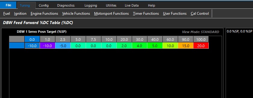
DBW Feed Forward %DC Table
Emtron uses a Feed Forward Table to provide a base duty for the PID function to operate from.
This allows for very fast response as the ECU has an initial lookup table before any PID is applied.
This table can be expanded into 3D (X axis enabled), and any runtime can be used.
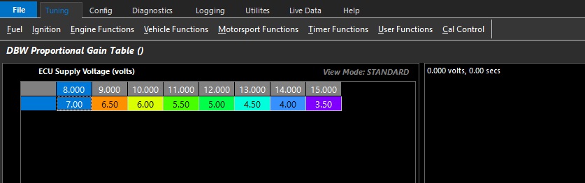
DBW Proportional Gain Table
Proportional gain controls how aggressive instantaneous correction must be.
This table can be expanded into 3D (X axis enabled), and any runtime can be used.
Above is an example where the change Proportional Gain is spanned across Battery Voltage.
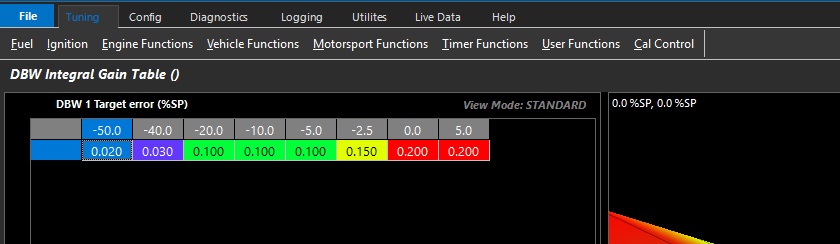
DBW Integral Gain Table
Integral gain controls how much adaptive correction is needed.
This table can be expanded into 3D (X axis enabled), and any runtime can be used.
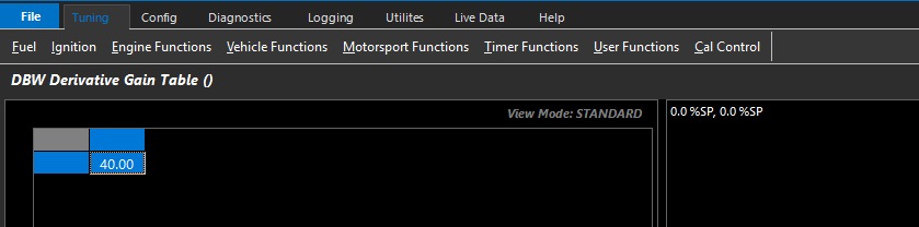
DBW Derivative Gain Table
Derivative gain controls predictive correction where gain is based on the rate of change of error.
This function is used to prevent overshooting targets by looking at a number of factors like rate of change, and P and I gain.
This table can be expanded into 3D (X axis enabled), and any runtime can be used.
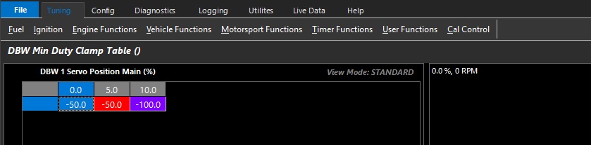
DBW Min Duty Clamp Table
Allows the user to set the minimum duty cycle that can be used by the closed loop system.
This table can be expanded into 3D (X axis enabled), and any runtime can be used.
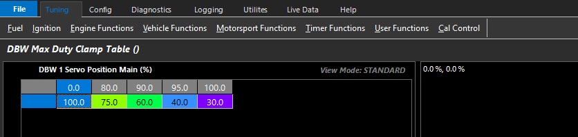
DBW Max Duty Clamp Table
Allows the user to set the maximum duty cycle that can be used by the closed loop system.
This table can be expanded into 3D (X axis enabled), and any runtime can be used.
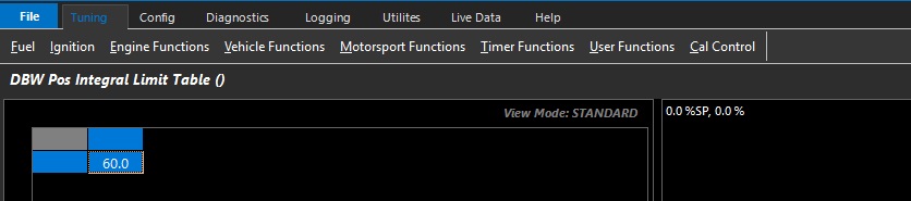
DBW Pos Integral Limit Table
Allows the user to set the maximum I gain compensation used by the closed loop system.
This table can be expanded into 3D (X axis enabled), and any runtime can be used.
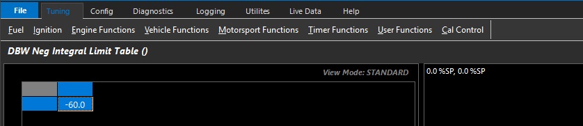
DBW Neg Integral Limit Table
Allows the user to set the minimum I gain compensation used by the closed loop system.
This table can be expanded into 3D (X axis enabled), and any runtime can be used.
NOTE:
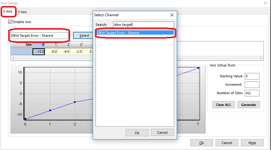
** If using dual DBW, then axis for target errors should be selected as “shared” runtimes. This tells the PID system to look at the respective DBW to apply closed loop gains
Tuning DBW PID
The DBW servo position is controlled in the Torque Management section.
The Pedal to Throttle Area Demand Translation Tables control the driver demand translation into throttle area demand.
The relationship between throttle area demand & DBW servo position is validated in Throttle Body Model > Throttle Body Area Table
The Pedal to Throttle Area Demand Translation Table does not relate to DBW servo position directly
To tune the DBW PID, it is useful to reconfigure the target function & zero the Pedal Position Demand Filter
For the purpose of tuning the PID, change the Pedal to Throttle Area Demand Translation Tables and the Throttle Body Area Table to be linear.
This will deliver a 1:1 relationship
Once PID control is validated, return to non linear Pedal to Throttle Area Demand Translation Tables & validate the Throttle Body Area Table
See Torque Management – Throttle Mass Flow
See Torque Management – Pedal to Throttle Demand Translation Table
See Throttle Body Setup - Throttle Body Area Table
DBW Input Setup
Filter Settings
FIlter Setting Minimum = 0 (OFF)
FIlter Setting Maximum = 100
Recommended Filter Range = 2 - 5
Single DBW.
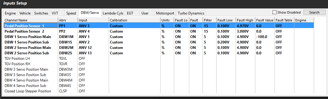
When using single DBW the following 4 inputs should be used. Although these inputs have no restrictions on their input assignment, the following is recommended.
DBW 1 Servo Position Main = Analog Volt 1
DBW 1 Servo Position Sub = Analog Volt 2
Pedal Position 1 = Analog Volt 13
Pedal Position 2 = Analog Volt 14
Dual DBW.
When using Dual DBW the following 6 inputs should be used. Although these inputs have no restrictions on their input assignment, the following is recommended.
DBW 1 Servo Position Main = Analog Volt 1
DBW 1 Servo Position Sub = Analog Volt 2
DBW 2 Servo Position Main = Analog Volt 3
DBW 2 Servo Position Sub = Analog Volt 4
Pedal Position 1 = Analog Volt 13
Pedal Position 2 = Analog Volt 14
DBW Pedal Position (PP) Calibration
Two options are available:
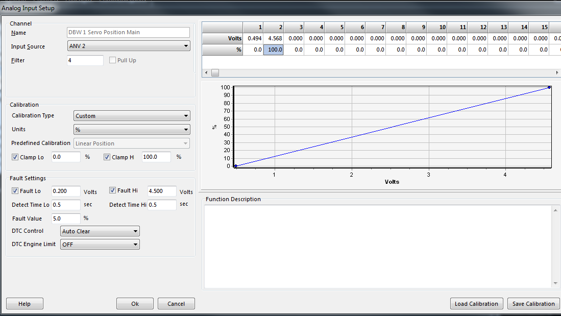
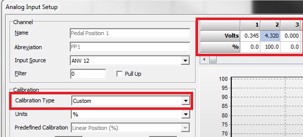
Manually enter in the Open and Closed voltages into each Calibration Table. Select Calibration Type to “Custom” and enter the value into the table as shown.
Automatic Calibration. Use the PP Closed/Open Calibration menu to automatically set these voltages. This can be access from Config View-> Engine Setup as shown.
When selected the PP1 and PP2 voltages will be written into their corresponding calibration tables. Make sure these channels have an Input Source set before selecting these menus.
These voltages can be viewed be going back to the Input Setup form as shown above.