Subsections of Engine Protection
Engine Protection
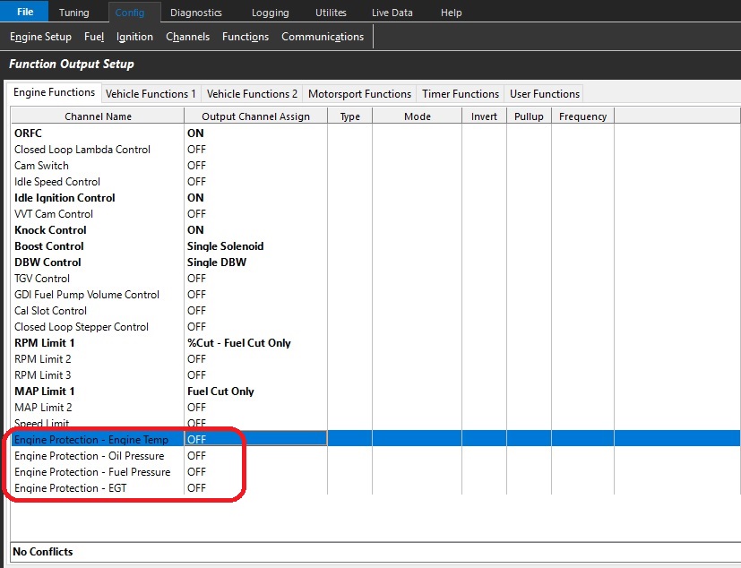
Emtron has 4 preset engine protection functions available in the software
Engine Temperature - Engine Temperature Sensor
Oil Pressure - Engine Oil Pressure Sensor (If Fitted)
Fuel Pressure - Fuel Pressure Sensor (If Fitted) - Fuel Pressure 1 Differential Offset runtime is utilised
EGT - EGT Sensors (If Fitted)
Each function must be enabled and cut type selected to become active.
(Fuel or Ignition Cut) - Fuel Cut is recommended
Once active, each function must be defined for correct operation.
Further engine protection can be defined by the user through the use of user functions and or timers.
Fuel Pressure 1 Differential Offset runtime
The Fuel Pressure 1 Differential Offset runtime reports the offset value in kPa between calculated and measured differential pressure.
Fuel Pressure sensor is required
.
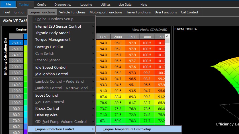
Engine Temperature Limit Setup
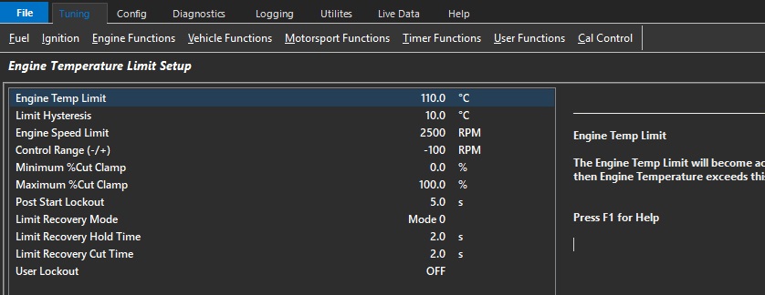
Engine Temp Limit
The Engine Temp Limit will become active then Engine Temperature exceeds this value.
Limit Hysteresis
Engine Temperature must return to the (Limit Value - Hysteresis Value) for the “Recovery Hold Time” entered before the Limit is switched OFF.
Engine Speed Limit
Engine speed limit applied when limit is active
Control Range (-/+)
Engine Speed Limit control range in RPM when limit is active
Minimum %Cut Clamp
Percentage cut applied to the engine at the start of the control range.
The cut type is defined in the Function Output.
Maximum %Cut Clamp
Percentage cut applied to the engine at the end of the control range
The cut type is defined in the Function Output.
Post Start Lockout
Will prevent the limit operating during crank and for a time after the engine has started.
Limit Recovery Mode
Controls the limit exit strategy.
Mode 0: Engine Temp < (Target Limit - Hysteresis) for the specified Hold Time.
Mode 1: Engine Temp < Target Limit - Hysteresis) for the specified Hold Time.
AND Engine Speed must have reached the Engine Speed Limit.
0: Mode 0
1: Mode 1
Limit Recovery Hold Time
When the Engine Protection limit is activated a time delay can be applied before the engine can recover.
This to prevent premature engine recovery from an Engine Protection event.
Limit Recovery Cut Time
Allow the cut to be progressively removed from the engine.
User Lockout
Allows the user to Lockout the Limit.
When the selected User Channel is ON a Limit request will still be generated but the engine will not be limited. ie %Cut will be zero.
Used for situations when you want to generate a Limit Request but not actually limit/cut the engine.
0: OFF
1: User Channel 1
2: User Channel 2
3: User Channel 3
4: User Channel 4
5: User Channel 5
6: User Channel 6
7: User Channel 7
8: User Channel 8
9: User Channel 9
10: User Channel 10
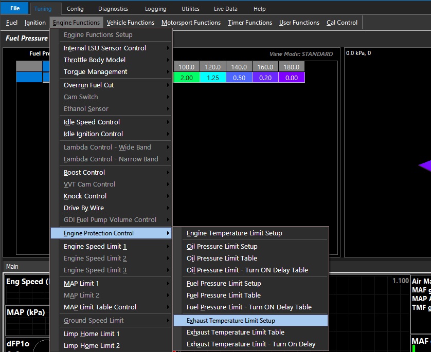
Exhaust Temperature Limit Setup
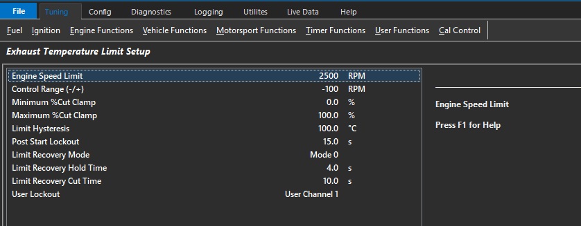
Engine Speed Limit
Engine speed limit applied when limit is active
Control Range (-/+)
Engine Speed Limit control range in RPM when limit is active
Minimum %Cut Clamp
Percentage cut applied to the engine at the start of the control range.
The cut type is defined in the Function Output.
Maximum %Cut Clamp
Percentage cut applied to the engine at the end of the control range
The cut type is defined in the Function Output
Limit Hysteresis
Exhaust Temperature must return to the (Limit Value + Hysteresis value) for the “Recovery Hold Time” entered before the Limit is switched OFF.
Post Start Lockout
Will prevent the limit operating during crank and for a time after the engine has started.
Limit Recovery Mode
Controls the limit exit strategy.
Mode 0: Exhaust Temperature > (Target Limit Temperature + Hysteresis) for the specified Hold Time.
Mode 1: Exhaust Temperature > (Target Limit Temperature + Hysteresis) for the specified Hold Time.
AND Engine Speed must have reached the value in the Engine Speed Limit setting
0: Mode 0
1: Mode 1
Limit Recovery Hold Time
When the Engine Protection limit is activated a time delay can be applied before the engine can recover.
This to prevent premature engine recovery from an Engine Protection event.
Limit Recovery Cut Time
Allow the cut to be progressively removed from the engine.
User Lockout
Allows the user to Lockout the Limit.
When the selected User Channel is ON a Limit request will still be generated but the engine will not be limited. ie %Cut will be zero.
Used for situations when you want to generate a Limit Request but not actually limit/cut the engine.
0: OFF
1: User Channel 1
2: User Channel 2
3: User Channel 3
4: User Channel 4
5: User Channel 5
6: User Channel 6
7: User Channel 7
8: User Channel 8
9: User Channel 9
10: User Channel 10
Exhaust Temperature Limit Table
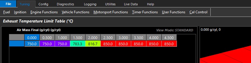
User defined Exhaust Temperature limit table. Limit is active above Deg C input values.
Exhaust Temperature Limit - Turn ON Delay Table (Sec)
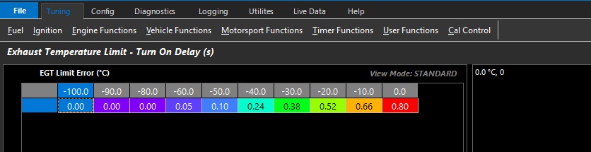
User defined limit activation delay table in seconds.
Fuel Pressure Limit Setup
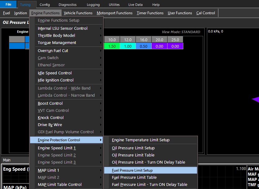
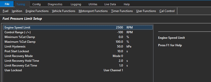
Engine Speed Limit
Engine speed limit applied when limit is active
Control Range (-/+)
Engine Speed Limit control range in RPM when limit is active
Minimum %Cut Clamp
Percentage cut applied to the engine at the start of the control range.
The cut type is defined in the Function Output.
Maximum %Cut Clamp
Percentage cut applied to the engine at the end of the control range
The cut type is defined in the Function Output
Limit Hysteresis
Fuel Pressure must return to the (Limit Value + Hysteresis value) for the “Recovery Hold Time” entered before the Limit is switched OFF.
Post Start Lockout
Will prevent the limit operating during crank and for a time after the engine has started.
Limit Recovery Mode
Controls the limit exit strategy.
Mode 0: Fuel Pressure > (Target Limit Pressure + Hysteresis) for the specified Hold Time.
Mode 1: Fuel Pressure > (Target Limit Pressure + Hysteresis) for the specified Hold Time.
AND Engine Speed must have reached the value in the Engine Speed Limit setting
0: Mode 0
1: Mode 1
Limit Recovery Hold Time
When the Engine Protection limit is activated a time delay can be applied before the engine can recover.
This to prevent premature engine recovery from an Engine Protection event.
Limit Recovery Cut Time
Allow the cut to be progressively removed from the engine.
User Lockout
Allows the user to Lockout the Limit.
When the selected User Channel is ON a Limit request will still be generated but the engine will not be limited. ie %Cut will be zero.
Used for situations when you want to generate a Limit Request but not actually limit/cut the engine.
0: OFF
1: User Channel 1
2: User Channel 2
3: User Channel 3
4: User Channel 4
5: User Channel 5
6: User Channel 6
7: User Channel 7
8: User Channel 8
9: User Channel 9
10: User Channel 10
Fuel Pressure Limit Table
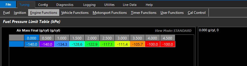
User defined Fuel differential offset pressure limit table. Limit is active below the offset kPa input values.
Fuel Pressure 1 Differential Offset runtime value is utilised
Fuel Pressure Limit - Turn ON Delay Table (Sec)
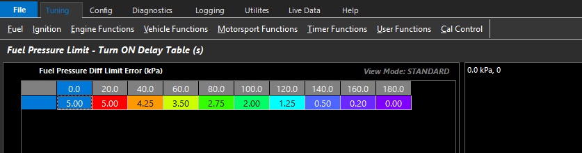
User defined limit activation delay table in seconds.
Limp Home Limits
This function provides Engine Speed Limiting when a DTC error occurs on an Input Channel. The operation of these table(s) can be controlled independently from each Input Channel setup page.
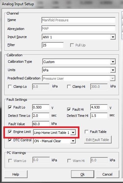
The following settings are not adjustable:
Start Cut - Set at 50%
End Cut - Set at 95%
Control Range = Set at +200 RPM
Oil Pressure Limit Setup
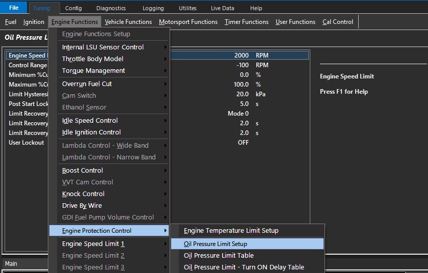
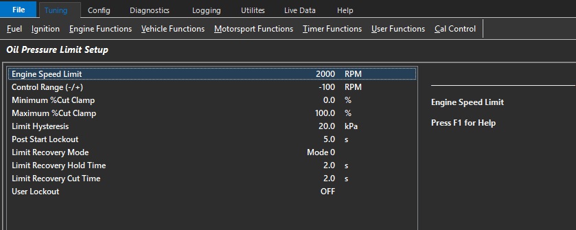
Engine Speed Limit
Engine speed limit applied when limit is active
Control Range (-/+)
Engine Speed Limit control range in RPM when limit is active
Minimum %Cut Clamp
Percentage cut applied to the engine at the start of the control range.
The cut type is defined in the Function Output.
Maximum %Cut Clamp
Percentage cut applied to the engine at the end of the control range
The cut type is defined in the Function Output
Limit Hysteresis
Oil Pressure must return to the (Limit Value + Hysteresis value) for the “Recovery Hold Time” entered before the Limit is switched OFF.
Post Start Lockout
Will prevent the limit operating during crank and for a time after the engine has started.
Limit Recovery Mode
Controls the limit exit strategy.
Mode 0: Oil Pressure > (Target Limit Pressure + Hysteresis) for the specified Hold Time.
Mode 1: Oil Pressure > (Target Limit Pressure + Hysteresis) for the specified Hold Time.
AND Engine Speed must have reached the value in the Engine Speed Limit setting
0: Mode 0
1: Mode 1
Limit Recovery Hold Time
When the Engine Protection limit is activated a time delay can be applied before the engine can recover.
This to prevent premature engine recovery from an Engine Protection event.
Limit Recovery Cut Time
Allow the cut to be progressively removed from the engine.
User Lockout
Allows the user to Lockout the Limit.
When the selected User Channel is ON a Limit request will still be generated but the engine will not be limited. ie %Cut will be zero.
Used for situations when you want to generate a Limit Request but not actually limit/cut the engine.
Example: During a Launch the Oil Pressure may temporally drop below the Limit Target.
A User Channel can be configured to lockout this limit during the first stages of Launch Control.
0: OFF
1: User Channel 1
2: User Channel 2
3: User Channel 3
4: User Channel 4
5: User Channel 5
6: User Channel 6
7: User Channel 7
8: User Channel 8
9: User Channel 9
10: User Channel 10
Oil Pressure Limit Table
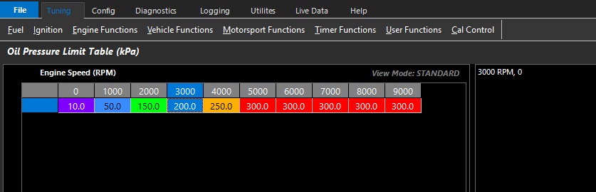
User defined oil pressure limit table. Limit is active above kPa input values.
Oil Pressure Limit - Turn ON Delay Table (Sec)
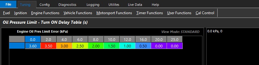
User defined limit activation delay table in seconds.