Gear Detection Setup
Gear Detection Setup
Gear Position Enable
Enables the Gear Detection
0 = OFF
1 = ON
Gear Position Calculation
Choose the method of Gear Position Calculation
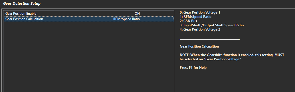
Various modes are available.
0 = Gear Position Voltage 1 - Input must be assigned and calibrated
1 = RPM/Speed Ratio - Gear is derived by RPM/speed channel defined (Under Gear Position RPM/Speed Setup)
2 = CAN Bus - Gear is received over CAN bus
3 = Inputshaft/Outputshaft Ratio - Gear is derived by calculating ratio of inputshaft/outputshaft speed
4= Gear Position Voltage 2 - Input must be assigned and calibrated