Sets the throttle position target that the DBW throttle will move to during the down shift.
This is an absolute position of the DBW Servo.
** This position will override other torque management functions regarding throttle control
Downshift Ignition Retard
Downshift Ignition Retard
This is the amount of Ignition Retard applied during the entire Downshift event
There are 2 modes :
Offset (Deg)
Percentage (%)
Downshift Next Gear Ignition Recovery Time
Downshift Next Gear Ignition Reovery Time
This is the total time the ignition retard will be phased back to 0.
Resolution = 1ms
Downshift Next Gear Solenoid Hold Time
Downshift Next Gear Solenoid Hold Time
This is the time the Solenoid stays ON once next gear stable has been achieved .
Resolution = 1ms
Downshift Pre-Cut Time
Downshift Pre-Cut Time
Engine Pre-Cut Time
Normally only required when the Throttle is held open on a downshift request. The Pre-cut allow the gearbox dog to be unloaded before the Downshift solenoid is switched ON. This allows the servo to be position before the power is re-applied for the downshift blip
0 = OFF
Downshift Request Enable Table
Downshift Request Enable Table
The Table output must be Enabled allowing the Downshift request to be valid.
(set to 100 if not required)
0 = Shift Request Disabled
100 = Shift Request Enabled
50 = No Change
Downshift Rev-Match RPM Target Correction
Downshift Rev-Match RPM Target Correction
This table controls adjusts the Rev-Match RPM Target +/- in units of %.
Use this to raise or lower the Rev-Match RPM Target
Downshift Setup
Downshift Debounce Time
The Downshift Paddle must be held for this time for the request to be valid.
This setting prevents accidental requests in harsh Motorsport
environments (vibration and vehicle harmonics).
Downshift Torque Reduction Type
0: Fuel Cut Only
1: Ign Cut Only
2: Fuel + Ign Cut
3: Off
\
Downshift Ign Retard Mode
0: OFF
1: Offset
2: Percentage
Applies the Ignition Retard as either an Offset or Percentage of Current Ign Angle
Example: Current Ignition Angle = 20.0 BTDC
Offset = 15.0 Deg Retard.
Ignition Angle during Gear Cut is = 20.0 - 15.0 = 5.0 Deg BTDC
Percentage = 50.0 % Retard.
Ignition Angle During Cut : = 20 - 50% x 20.0 = 10.0 Deg BTDC
Downshift Pre-Cut Percentage Cut
Fuel and/or Ignition Cut Percentage used in the Downshift Precut.
Downshift Throttle Override
0: OFF
1: DBW 1 - Duration Table
2: DBW 1 - Function Controlled
3: Throttle Solenoid - Duration Table
4: Throttle Solenoid - Function Controlled
This setting overrides or “blips” the thottle on downshift .
Duration Table is Open Loop mode and used to control the length of time the DBW or Solenoid is held open.
Function Controlled is Closed Loop so the Gearshift
Function is used to control the length of time the DBW or Solenoid is held open.
The goal is to increase the airflow into the engine to match the engine speed of the requested downshift gear.
NOTE: The Rev-matching Limit setting can also be switched ON, which limits the engine to the correct rpm assuming enough air has benn introduced into the engine.
Downshift Rev-Matching Limit
0: OFF
1: ON - Outputshaft Speed
2: ON - Outputshaft Speed Calculated
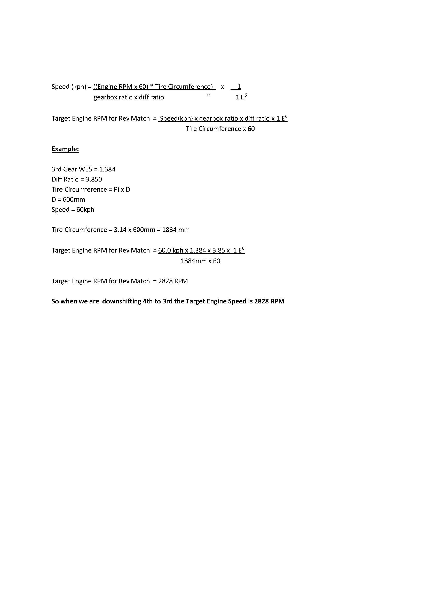
Rev-matching Downshift Function will Limit the engine RPM to match the requested Downshift gear. The ECU uses Output shaft RPM and Transmission ratios between the current gear and requested gear to calculate a Rev-matched RPM Target.
i.e. Matching Transmission Input and Output speed referenced by Gear Ratio
Make sure the “Downshift Rev-Match RPM Target Correction “table is setup/Initialised correctly
You also MUST introduce extra air into the engine either by using the DBW or a solenoid to manual open the throttle.
(Select this from the Downshift Throttle Override setting)
Example:
Current rpm = 6000, In 4th gear and downshifting to 3rd
Gear ratio 4th = 1.000
Gear ratio 3rd = 1.230
Target Downshift Engine Speed RPM = 6000 x 1.230/1.000
Target Downshift Engine Speed RPM = 7380
So the ECU will Limit the Engine Speed to 7380 assuming sufficient air has been introduced
NOTE: The Gear Ratio Table MUST be completed for this function to operate correctly. See Vehicle Functions -> Vehicle Dynamics menu.
Once DBW has returned to within 5% of the Target this timeout gets applied. When Time = 0 the Rev-match limit is then removed.
ONLY applies to DBW applications.
Downshift Next Gear Timeout
The Next Gear MUST be reached within this time for the Downshift to be valid. If this does not occur the ECU will re-try the gear shift by the number of times set in the Upshift “Downshift Re-retry Count” Setting.
Time starts when Downshift Solenoid is switched ON.
Typical Value = 100ms
Downshift Re-Try Count
The number of time the ECU will re-attempt a failed Gear Shift.
ONLY Applies when Electronic(Paddle) mode selected
Typical Value = 3
Downshift Stacking Limit
Sets the maximum number of Upshift Requests that can be stacked.
0 =OFF
Downshift Min Engine Speed
The Engine Speed MUST be less than this value for the Downshift request to be valid
0 = OFF
Downshift Min Throttle
The Throttle Position MUST be less than this value for the Downshift request to be valid
0 = OFF
Downshift Max Pedal
The Pedal Position 1 max position for Dowshift request to be valid
0 = OFF
Downshift User Enable
The User Channel when selected must be ON
for the Downshift request to be valid.
0: OFF
1: User Channel 1
2: User Channel 2
3: User Channel 3
4: User Channel 4
5: User Channel 5
6: User Channel 6
7: User Channel 7
8: User Channel 8
9: User Channel 9
10: User Channel 10
Downshift Force Hysteresis
Prevents Gearshift re-triggering.
Example:
Gear Force Positive = 8kg
Downshift Force Hysteresis = 60%
Downshift will be triggered when Gear Force > 8kg.
Once complete the Gear force will not be allowed to trigger the Gearshift until it falls below 60% of 8kg ..ie Force MUST be less than 3.2Kg (8- 4.8)
Downshift Solenoid Delay
Downshift Solenoid Delay
This is the length of time from the initial Downshift Request to when the Downshift Solenoid is switched ON.
Resolution = 1ms
Downshift Throttle Duration
Downshift Throttle Duration
Sets the Duration of the DBW throttle position change when Force is used
Sets the Timeout of the DBW throttle position change when Paddle shift is used
** This position will override other torque management functions regarding throttle control
Gear Cut End Source
Gear Cut End Source
This setting controls the way the cut is to be ended once triggered. The following settings are available :
0: Timed Setting uses the Cut Time Table to
control the Cut length
1: “Clutch Switch” Status changing to OFF ends
the Cut
2: “Gear Cut Switch” Status changing to OFF ends
the Cut
3: If Positive Force Started the cut, the cut End
will occur when the Force is less than the
Postive Force Threshold - Gear Cut Force Hysteresis.
The inverse applies for a Negative Force Start Cut
Example:
Force Threshold = 8.0kg

Gear Cut Force Hysteresis = 3.0kg

Start Cut at > 8.0 kg

End Cut at < 5.0 kg

Force Threshold = -6.0kg

Gear Cut Force Hysteresis = 3.0kg

Start Cut at > -6.0 kg

End Cut at < -3.0 kg
NOTE: “Gear Cut Start Source” MUST be
selected as 2 (Gear Shift Force) for this setting
to work
4: Next Gear Stable will determine the cut time. Once
the next gear is confirmed the ECU will initiate a cut end
Gear Cut Ign Retard Mode
Gear Cut Ign Retard Mode
Applies the Ignition Retard as either an
Offset or Percentage of Current Ign Angle
Example: Current Ignition Angle = 20.0 BTDC
Offset = 15.0 Deg Retard.
Ignition Angle during Gear Cut is
= 20.0 - 15.0 = 5.0 Deg BTDC
Percentage = 50.0 % Retard.
Ignition Angle During Cut :
= 20 - 50% x 20.0 = 10.0 Deg BTDC
0: Offset
1: Percentage
Cut Level Recovery Time Table
Cut Level Recovery Time Table
The total time that the cut will be phased back to 0.
Gear Cut Start Source
Gear Cut Start Source
This is the source ECU uses to trigger the cut for gear shift. There are three methods that can be selected :
0: Digitial Input set to Clutch Switch
This setting will allow the system to trigger by “Clutch.Switch” input.
1: Digitial Input set to Gear Cut Switch
This setting will allow the system to trigger by “Gear Cut Switch” Input. Commonly this signal is supplied by a gear shifter mounted switch
2: Gear Shift Force
This setting will allow the system to trigger by “Gear Shift Force” Input. Commonly this signal is supplied a gear shift mounted amplified strain gauge output. This is generally the best method for triggering but does require hardware which can provide the ECU a voltage output based on the force.
Cut Level Table
Cut Level Table
This is the engine cut % applied when gear cut it active
Cut Time Table
Cut Time Table
This table sets the cut time if the “Gear Cut End Source” is set
to “Timed”
Cut Timeout Table
Cut Timeout Table
Time in seconds that the cut time will be clamped to. No matter what
setting is configured the total cut time will be limited by the ECU to
this time.
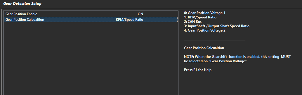
Gear Detection Setup
Gear Detection Setup
Gear Position Enable
Enables the Gear Detection
0 = OFF
1 = ON
Gear Position Calculation
Choose the method of Gear Position Calculation
Various modes are available.
0 = Gear Position Voltage 1 - Input must be assigned and calibrated
1 = RPM/Speed Ratio - Gear is derived by RPM/speed channel defined (Under Gear Position RPM/Speed Setup)
2 = CAN Bus - Gear is received over CAN bus
3 = Inputshaft/Outputshaft Ratio - Gear is derived by calculating ratio of inputshaft/outputshaft speed
4= Gear Position Voltage 2 - Input must be assigned and calibrated
Proper gear detection and channel calculation such as Input shaft Speed (Calc) are important for functions in the ECU such as Motorsport Gearshift control (regarding rev matching control), some Application Build systems (CAN Integration), and other general functions in the ECU that may be being used.
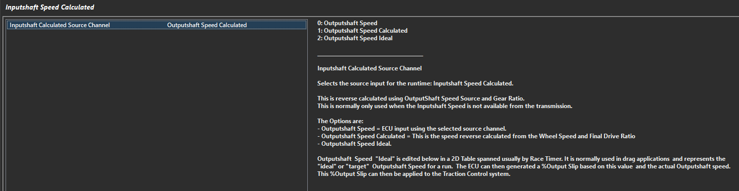
Input/Outputshaft Speed Calculations
Inputshaft speed Calculated can be derived from looking at Outputshaft Speed Channels -> Vehicle Dynamics -> Inputshaft Speed Calculated
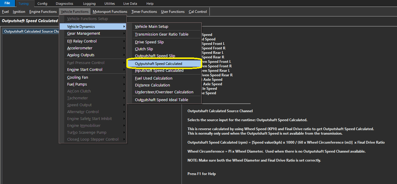
“1” Output Shaft Speed Calculated is derive from selecting a calibrated speed channel. -> Vehicle Functions -> Vehicle Dynamics -> Outputshaft Speed Calculated
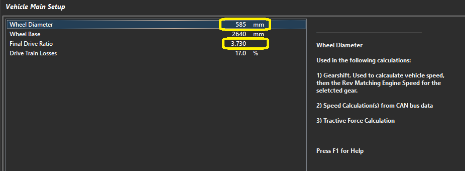
** The ECU generates this channel by deriving the speed through the wheel circumference and final drive under Vehicle Dynamics -> Vehicle Main Setup ->
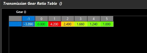
The Inputshaft speed is calculated furthermore through the Transmission Ratio Table. Vehicle Dynamics -> Transmission Gear Ratio Table ->
Validating Inputshaft speed (Calc) channel
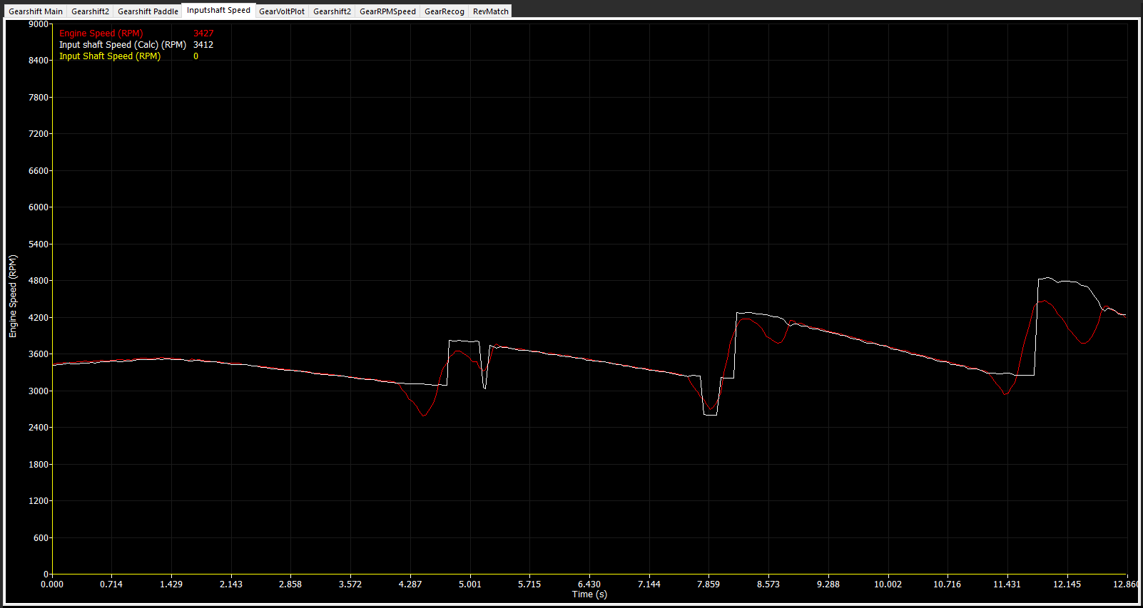
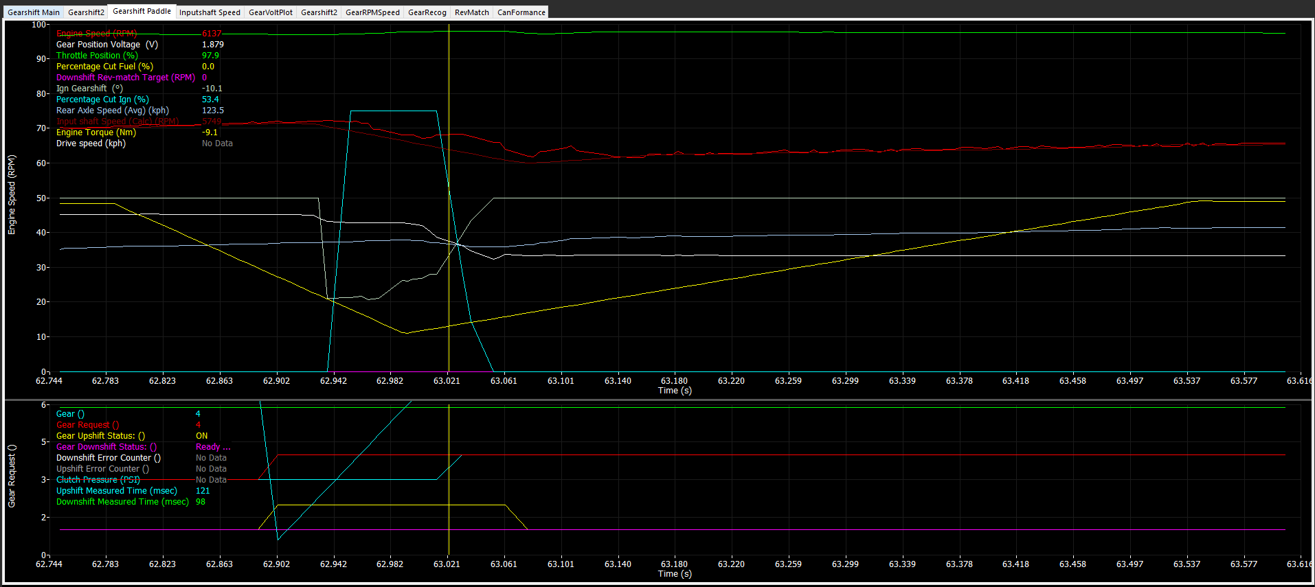
To validate Inputshaft speed (Calc), logging engine speed vs Inputshaft Speed (Calc) can be plotted ->
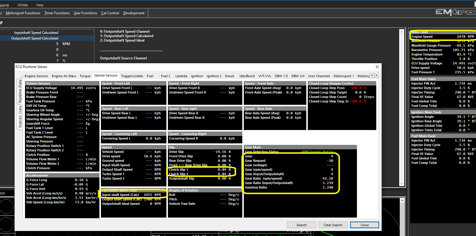
Also by looking at runtimes for channel comparisons can be done ->
** Note Gear Ratio (Input/Outputshaft) (calculated from Input shaft speed (Calc) vs Output shaft Speed (Calc) vs Gearbox Ratio (Transmission Ratio tabe) is the same
** Note Clutch Slip Channels are near 0% (calculated % difference between Engine Speed and Clutch Slip Source Channel)
(define clutch slip in Tuning -> Vehicle Functions -> Vehicle Dynamics -> Clutch Slip = Currently Set to Inputshaft Speed Calculated)
** If there is error in Input shaft Speed (Calc) vs Engine Speed (therefore there will be error in Gear Ratio (Input/Outputshaft) and Clutch Slip), then settings/calibration needs attention in regards to speed sensor calibration, wheel diameter, final drive, or transmission ratios
Gear Force Negative
Gear Force Negative
This is the negative force required to trigger a cut event if
this “Gear Cut Start Source” is configured to “Gear Shift Force”
Gear Force Positive
Gear Force Positive
This is the positive force required to trigger a cut event if
this “Gear Cut Start Source” is configured to “Gear Shift Force”
Fault Mode Cut Time
Fault Mode Cut Time
Gearshift Mode:
This table sets the open loop cut time when the system is in fault mode.
(For example Gear Position sensor has failed or Gear Position Tracking Error)
Gearcut Mode:
This table sets the cut time if the “Gear Cut End Source” is set to “Timed”
Gear Shift Control
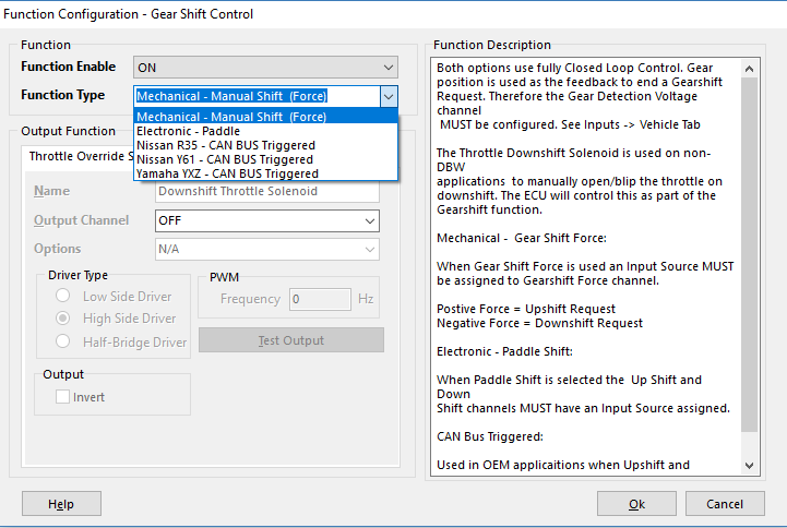
Gearshift Control Function Setup
Emtron has multiple methods of Gearshift Control
Config, Function Setup, Motorsport, Gearshift Control
Mechanical - Manual Shift (Force)
Electronic - Paddle
There are also other CAN BUS Triggered modes for Application Build versions.
** See those Application Build Manuals for details
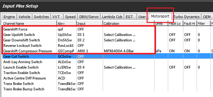
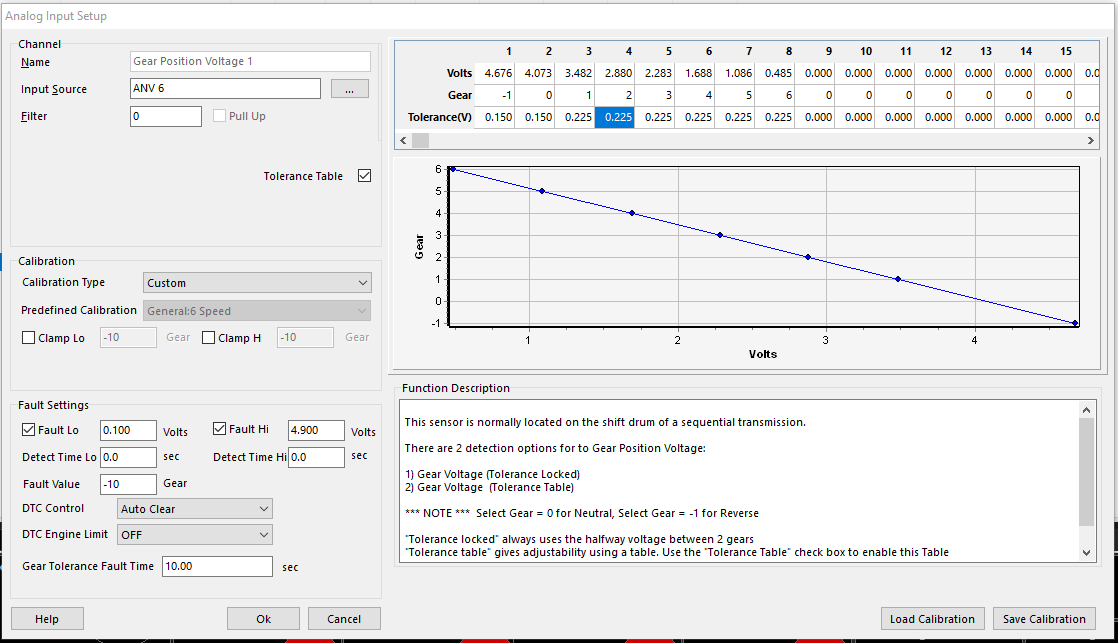
Configure Gear Position using the “Gear Detection Voltage” channel . This is normally a barrel position sensor located on the sequential gearbox. See Config View -> Inputs -> Vehicle Tab
Configure the Inputs. Configure the following from the Inputs -> Motorsport tab:
Paddle Shift mode
Upshift Paddle Input
Downshift Paddle Input
Reverse Lockout Switch if required
Compressor Pressure Input if required
In Force Shift mode
Gearshift Force Input
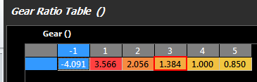
For Paddle Shift to function correctly and safely at least least two(2) gear channel needs to be tracked for redundancy purposes. Commonly a Gear Detection voltage will be reported from a gear drum mounted to the transmission along with a speed sensor which may be used by the ECU to calculate the gear along with generating Engine Speed requests fro rev-matching limiters. The vehicles wheel diameter and final drive ratio should be confirmed correct. Then enter the correct transmission gear ratios into the table :
See Vehicle Dynamics->Vehicle Main The gear ratio table needs to be accurately set for this to occur.
. See Tuning view -> Vehicle Functions -> Vehicle Dynamics menu -> Transmission Gear Ratio table. Use -1 for Reverse.
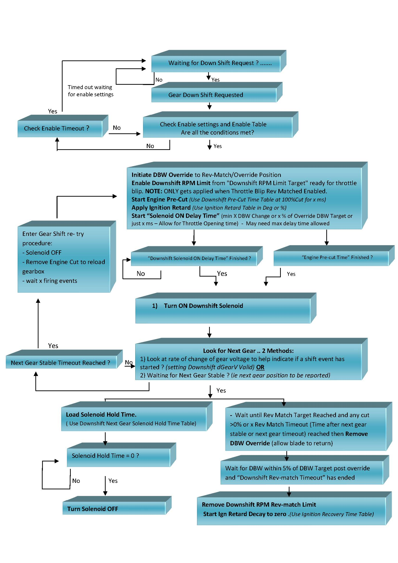
Gear-Shift-Down-Shift-Flow
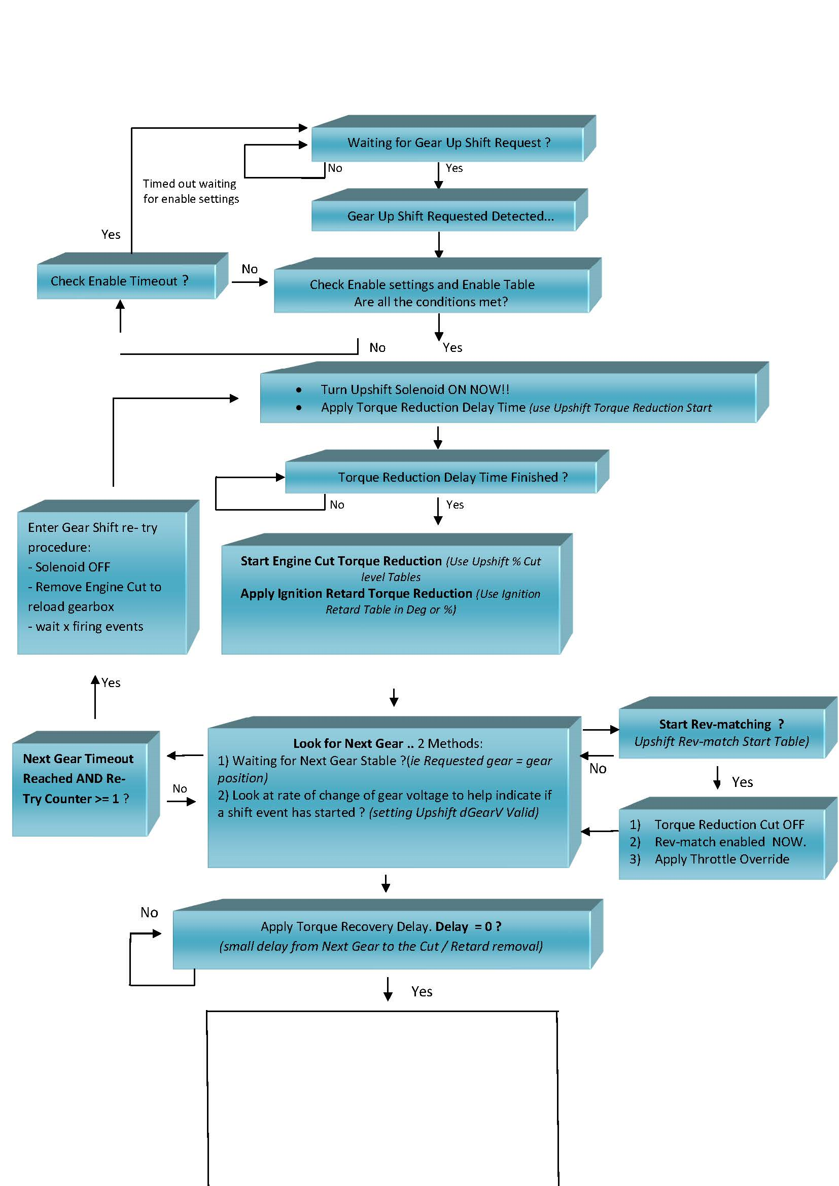
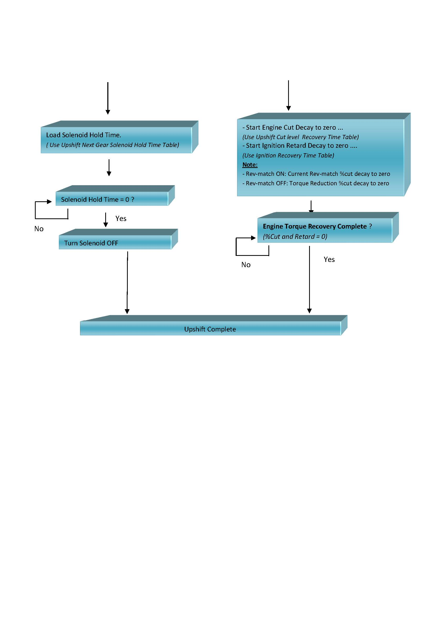
Gear-Shift-Up-Shift-Flow
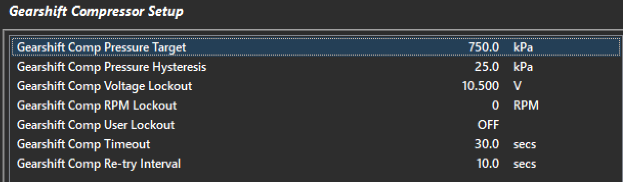
Gearshift Compressor Setup
Gearshift Compressor Setup
Gearshift Comp Pressure Target
Pressure Target for Compressor. The Output will be switch off when the pressure is reached.\
Gearshift Comp Pressure Hysteresis
This value is subtracted from the Pressure Target and determines when the Output will be switched back ON.
Pressure Target = 150.0 PSI
Pressure Hysteresis = 10.0 PSI
The Pump will stay ON until 150.0 PSI is reached. The Pump will then turn OFF. When the pressure drops to 140 PSI to pump will switch back ON\
Gearshift Comp Voltage Lockout
The Gearshift Compressor Output will be switched OFF below this Voltage. Used normally to switch OFF the Compressor to prevent battery drain in Low Voltage situations.
0 = OFF\
Gearshift Comp RPM Lockout
The Gearshift Compressor Output will be switched OFF below this Engine Speed. Used normally to switch OFF the Pump during low RPM and cranking.
0 = OFF
Typical Value = 400 RPM
Gearshift User Lockout
The Gearshift Compressor Output will be switched OFF when the User Channel is ON/Active.
0: OFF
1: User Channel 1
2: User Channel 2
3: User Channel 3
4: User Channel 4
5: User Channel 5
6: User Channel 6
7: User Channel 7
8: User Channel 8
9: User Channel 9
10: User Channel 10
Gearshift Comp Timeout
With the Compressor ON, if the Target pressure cannot be reached within this timeout value the Output will be switched OFF. The timer will only be reset when the Lockouts become active OR the Re-try Interval is reached/used.
0 = OFF
Typical Value = 30secs
Gearshift Comp Re-try Interval
In the event the Timeout is reach and the output is switched OFF the system will switch the ouput back ON at this interval in an attempt to keep system pressure. This event normally occurs when the feedback input fails.
0 = OFF
Gearshift Compressor Status
0    Disabled

1    OFF

2    ON

3    OFF - RPM Lockout

4    OFF - User Lockout

5    OFF - Timeout

6    OFF - I/P not selected

7    OFF -  Input in Fault

8    OFF - Voltage Lockout
Gearshift Control Status
0    Disabled

1    OK

2    X Gear I/P Fault - Open Loop

3    X Gear Position Setup Err

4    X Gear Request Setup Err

5    X Gear Voltage Input OFF

6    X Gear Cut Func ON

7    X Rev-match set Gear Ratios

8    X Missing UpShift Output

9    X Missing DownShift Output

10    X Missing UpShift Input

11    X Missing DownShift Input

12    X Missing Force Input

13    X Timeout Setting LOW
Gearshift Control Tuning
Gearshift Control Tuning
The first step in the tuning section of the function is to setup the gear request input method.
The target compressor pressure represented in kpa. The transmission manufacturer should be able to advise on the maximum pressure to operate with however common settings are between 600-800kpa.
Gearshift Comp Pressure Hysteresis
The amount the compressor pressure needs to drop below the target before the compressor is switched back on. Ideally the supply pressure should be kept as constant as possible for consistent shift performance.
Gearshift Comp Voltage Lockout
Minimum ECU supply voltage to allow the compressor to operate.
Gearshift Comp RPM Lockout
Minimum Engine Speed to allow the compressor to operate. This is usually set to reduce battery load while the vehicle supply is powered.
Gearshift Comp User Lockout
A user channel may be used to lockout the compressor if the default lockouts are not satisfactory for the application.
Gearshift Comp Timeout
If the compressor target is not reached within this time the ECU will assume there must be a fault in the system. Most common faults would be a leak or faulty compressor motor.
Gearshift Comp Re-Try Interval
Once the compressor pressure target is not reached within the time out the ECU will wait for the re-try interval and attempt to turn on the compressor again.
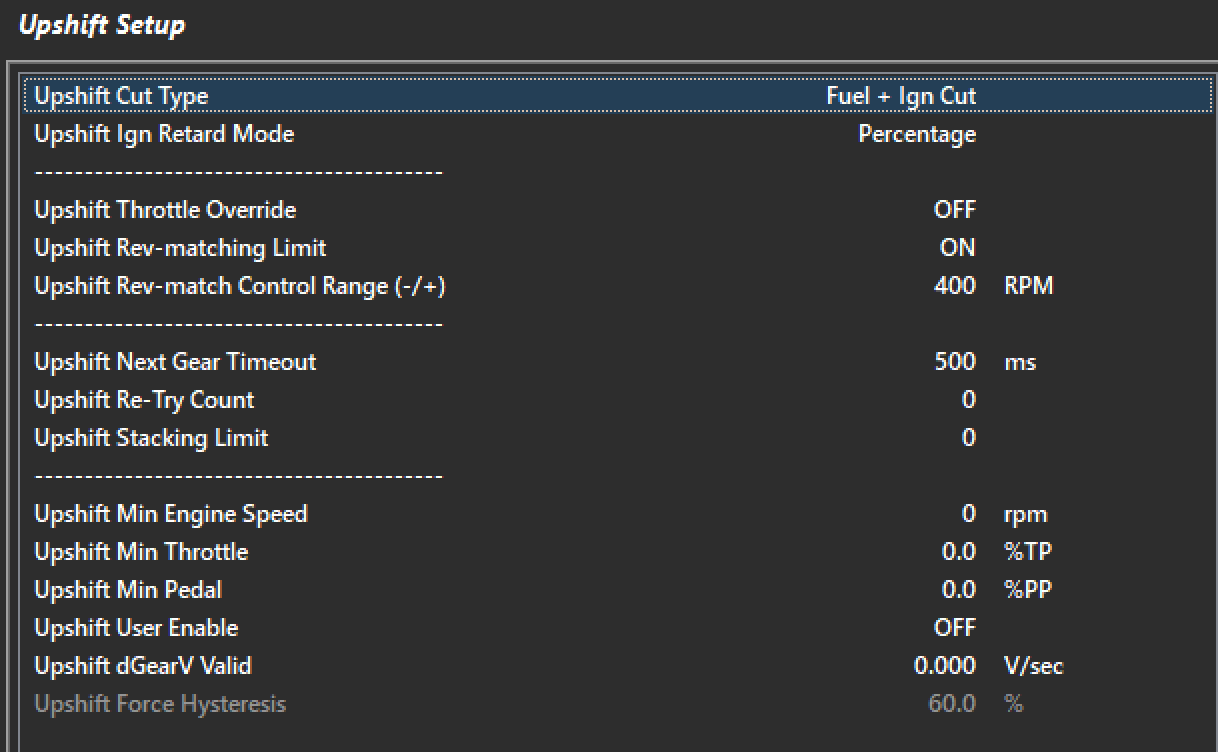
Upshift Setup
Tuning View -> Motorsport Functions -> Gearshift Control -> Upshift Control -> Upshift Setup
Upshuft Cut Type
This sets the type of cutting used for gearshift control.
Fuel Cut Only
This system will cause a slower recovery of the engine from the cut leading to longer overall effective shift times. The will lead to quieter operation on the gearshift due to lack of unburnt fuel in the exhaust to ignite.
Ignition Cut Only
This system will cause very fast recovery as the fuel film does not require rebuilding after the shift recover. Depending on the tuning strategy and hardware careful consideration needs to be taken when choosing this cutting method. Unburnt fuel igniting in the exhaust can lead turbocharger and exhaust damage. Valve train needs to be considered also when choosing this system.
Fuel + Ign Cut
This system employs a combination of both fuel and ignition cutting strategies. This system is generally the most favored method as there is a lot of flexibility with the cut strategy balance.
Upshift Throttle Override
The ECU can override the DBW throttle position during and Upshft event. Generally for the fastest shifting performance cutting and retard strategies alone will allow will achieve the best results. During low traction surface shifting is can be possible to help unload the dog by closing the throttle during the shift.
Upshift Rev-matching Limit
This setting toggles the rev matching feature. The ECU can perform a user level cut strategy which then leads into the Engine Speed Limit rev-matching strategy. It is advised to always have this feature enabled for best performance.
Upper Rev-match Control Range (+/-)
This is the range the Engine speed limit controls the cut %. For upshift this should be a positive(+ve) number. 400rpm is a good starting range. Once the engine is within 400rpm of the ECU calculated rev-match target cut will commence.
Upshift Re-Try Count
The ECU employs a strategy of retrying the shift if it is deemed to have either failed or will fail based on a the in coming sensor data.
Upshift Next Gear Timeout
This is the timeout allowed for the upshift event to occur in total. All cutting and instructions should have completed within this time. If the gear has failed to achieve a shift and upshift counter will increment. All retries would have occurred within this timeout.
Upshift Stacking Limit
The ECU has the ability to increment a shift request counter for the purpose of “stacking” shifts. This number limits the amount of shifts that can be stacked. When the conditions are satisfied a shift will occur and the stack count will decrement until the count reaches zero.
Upshift Min Engine Speed
Upshift Min Throttle
Upshft Min Pedal
Upshift User Enable
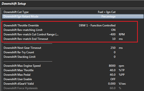
Downshift Setup
Rev-matching describes the process of matching engine speed to the gear you are shifting into/requested gear. With Downshifting the Engine Speed must be increased so additional air needs to be introduced with the ECU supporting a variety of methods. This reduces stress on the drive-line.
The Downshift setting can be found in the Tuning View -> Motorsport Functions -> Gearshift Control -> Downshift Control menu.
Downshift Cut Type
This setting is used in 1) The Pre-Cut Downshift function which allows the “dog” to be unloaded 2) For Rev-Matching
Downshift Throttle Override
Allows additional air to be introduced into the engine on downshift. There are 5 options:
4: Throttle Solenoid - Function Controlled (Non DBW application)
The “Duration Table” is an open loop control. A table is used to enter in the length of time the Downshift Throttle Override will be active
“Function Controlled” allows the ECU to dynamically change the Throttle Override time based on the functions state. For example as the Gearshift “Next-Gear Stable” time varies, the ECU dynamically adjusts the Throttle Override time to match.
NOTE: You can use this function with the Rev-matching OFF. However, there is nothing limiting the engine speed so caution should be used when setting the amount of additional air introduced into the engine.
Downshift Rev-matching Limit
The Downshift Rev-matching Limit function will Limit the engine RPM to match the requested downshift gear. The ECU uses the transmission gear ratios between the current gear and requested gear to calculate a Rev-matched RPM Limit Target.
Make sure the Downshift Rev-Match RPM Target Correction table is setup correctly. Initialise to 0% for first time setups.
Additional air MUST also be introduced into the engine, either by using the DBW or a solenoid to manual open a cable throttle. The ECU will control this with options available in the Downshift Throttle Override setting.
Downshift Rev-Match Cut Control Range
Controls the RPM Range over which the engine will be cut when the Downshift limit is active. The Min Cut and Max Cuts are locked respectively at 0% and 95%
Example:
Rev-match RPM Target = 4000
Min Cut = 0%
Max Cut = 95%
Range = +400 0RPM,
Engine Speed: 4000 RPM = 0% Cu
Engine Speed: 4400 RPM = 95% Cut
Range = -400 RPM (Recommended)
Engine Speed: 4000 RPM = 95% Cut
Engine Speed: 3400 RPM = 0% Cut
Downshift Rev-Match End Timeout
The Rev-match Limit will be removed once the DBW has returned to within 5% of its normal position. This Timeout allows additional time for the system to stabilize before the limit is removed. If this setting is required typical times range from 10 - 50ms.
NOTE: This setting ONLY applies to DBW applications. If not used set to zero.
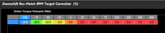
Downshift Rev-Match RPM Target Correction Table
Applies a percentage correction to the calculated Rev-Match Target. The range is +/- 100%.
Example:
Rev-match RPM Target = 4000
Driver Torque Demand = 25Nm
Based on the below table the %Correction is 5%.
Final Rev-match RPM Target = 4000 x 1.05 = 4200 RPM
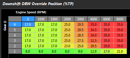
Downshift DBW Override Position Table
Sets the Servo Position target that the DBW will move to during the downshift. This is an absolute position. The below table shows a typical 4 cylinder engine example.
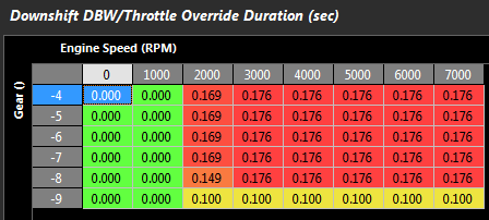
Downshift DBW/Throttle Override Duration Table
The length of time the air override system is introducing additional air during the downshift. This can be a Solenoid pushing on a cable throttle or DBW. This table is only enabled when the Downshift Throttle Override setting is non-function controlled i.e. Open Loop Duration Table as shown below.
Final Example
In 4th gear, downshifting to 3rd:
Downshift Rev-Match Control Range = -400 RPM
Current rpm = 6000
Gear ratio 4th = 1.000
Gear ratio 3rd = 1.230
Downshift Rev-Match RPM Target Correction = 2%
Target Downshift RPM = 6000 x 1.230/1.000
Target Downshift RPM = 7380
Apply 2% Target Correction:
Target Downshift RPM = 7380 x 1.02
Target Downshift RPM = 7527
Downshift RPM High: 7527 RPM at 95% Cut
Downshift RPM Low: 7127 RPM at 0% Cut
So the ECU will Limit the Engine Speed between 7127 and 7527 assuming sufficient air has been introduced
Gearshift Downshift Status
0    Disabled

1    Ready ...

2    ON

3    OFF - Max TPS

4    OFF - Max RPM

5    OFF - User

6    OFF - Enable Table

7    OFF - Max PPS

8    OFF - Gearshift Status

9    OFF - SPARE

10    Rev: Dnshift Sw Timer

11    R: Upshift Sw Waiting ..

12    R: Reverse Sw Waiting ..

13    R: Clutch Switch

14    R: Clutch Position

15    R: User Lockout

16    R: Speed Lockout

17    R: RPM Lockout
Gearshift - Paddle
Gearshift without “shift position” – Tolerance Voltage
Larger tolerance voltage number will achieve next gear stable sooner. Consider volt change per gear, to determine tolerance volt.
Gear volt spread is 0.60x volt. 0.225 tolerance will achieve “gear change” 63% of the way through the barrel turn.
This is a way control the shift timing if using “Next Gear Stable” function
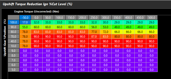
Above example is vehicle using a static cut value (75%).
Next Gear % Cut Level and Ignition Retard Recovery Time are being leveraged to phase back in engine power.
Pre-loading Gearbox
Necessary to achieve swift ratchet action, similar to a “stick” setup where you’d deny cut until a specific force on the shifter.
Mechanical lag of linakge, air lines, etc – all contribute to needing pre-loading.
Cars with high forward momentum will need pre-loading to ensure the middle phase of the gearshift happens at the right time, when the dogs are fully dis-engaged.
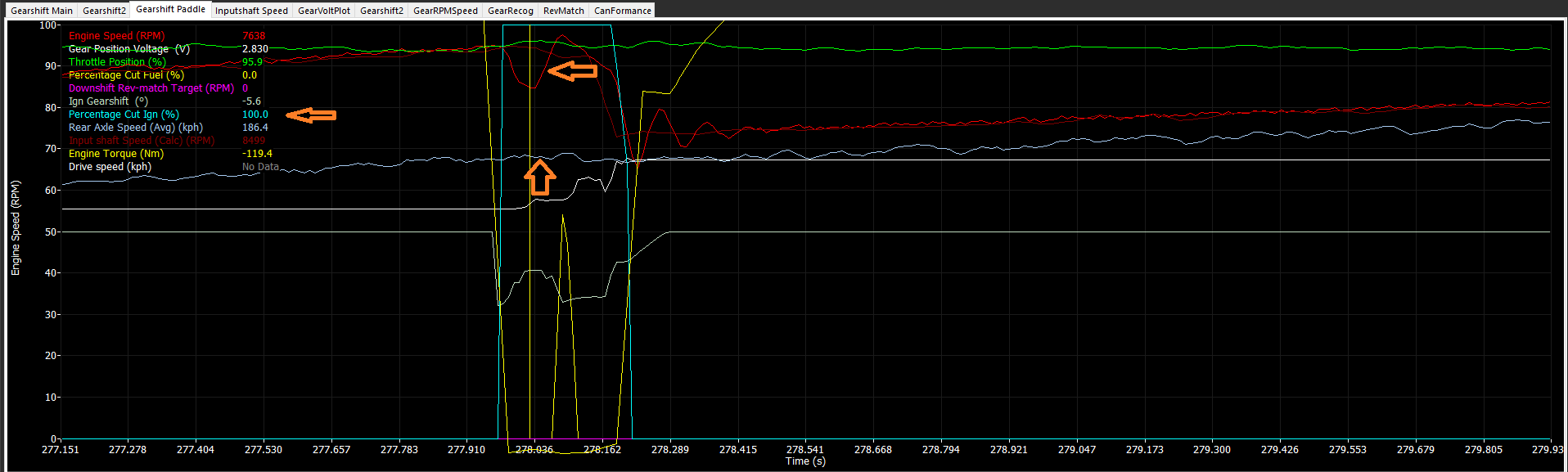
Observe engine in full cut off, engine speed decelerating, but speed still increasing. The barrel has not turned at the right time (when the engine speed decelerated) and caught the previous gear deceleration side of the dog hanging the upshift up.
Pre-loading can be done with Torque Reduction Delay table, or if Shift Position is available, in full closed loop ->
Torque Reduction and Re-Introduction
Reduction in torque can be achieved many ways with fuel, ignition, or both cut tables. Retard tables. Rev matching cut functions, and even DBW target hijacking.
Different scenarios will call for different methods of reduction types.
On turbocharged engines, using too much cut may reduce exhaust energy affecting turbine speed.
Too much retard may increase exhaust energy
A global boost control comp for “Ignition Trims Total” is suggested
Re-Introduction of torque is critical to prevent drivetrain from clashing, bouncing on dogs (drive/decel), and creating excessive ringing in the driveline.
Plotting/observing Engine Torque (requires tuned torque model) runtimes can help what the engine is doing during the shift quickly
Using Shift Position channels in cut tables
Cut Recovery Time table functions off values in the cut table – if last value is “0” then recovery time has nothing to recover from
Tolerance Voltage in the Gear Volt input setup should be considered. Suggest using a lower tolerance voltage to control the ECU through the shift
Gearshift Setup
Gear Position Order
0: N123456
1: RN123456
2: 1N23456
This settings allows the ECU can determine the correct shift and half-shift sequence
Option 1: RN123456.
In some transmissions neutral is located half-way between R and 1st. To allow Neutral to be selected, the “Half-Shift” setting should be enabled.
NOTES:
** 1st -> Neutral will require a Half-Shift. (Downshift Solenoid will be modulated)
** Reverse -> Neutral will require a Half-Shift (Upshift Solenoid will be modulated)
** Neutral to reverse Half-Shift is not required as reverse gear is located at the end of the shift drum.
Option 2: 1N23456
In this configuration neutral is located half-way between 1st and 2nd. To allow Neutral to be selected, the “1st -> N Half-Shift” setting should be enabled.
NOTES:
** 1st -> Neutral will require a Half-Shift (Upshift Solenoid will be modulated)
** N -> 1st upshift request, the ECU will activate the downshift solenoid
** Neutral to 1st Half-Shift is not required as 1st gear is located at the end of the shift drum.
Gear Position Tracking
0: OFF
1: RPM/Speed Ratio
2: Gear Detection Voltage 2
3: InputShaft /Output Shaft Speed Ratio
Gearshift tracking feature helps reduce transmission damage by cross referencing two independent Gear positions at the start of a gearshift. The ECU uses the Main and Tracking Gear Positions to achieve this.
It is HIGHLY recommended to use this feature.
Main/Primary Gear Position: The Gear Position Voltage 1 Input channel is used.
Tracking Gear Position: This is selectable under this setting.
When the Main and Tracking Gear positions don’t match the actual Gear Position cannot be determined with absolute certainty. This can be caused by a sensor entering a Fault condition or an absolute tracking error.
To prevent transmission damage the following precautions are used:
The ECU requires the clutch to be depressed before a shift can occur. The ECU checks this condition by looking at the Clutch Switch Status or Clutch Pressure. The ECU will NOT upshift or downshift until the clutch is depressed.
The Gearshift runs in open-loop mode. The gearshift time is calculated from the “Fault Mode Cut Time” table and does not use the “next gear stable” strategy.
Rev-matching is disabled.
In the event the Main Gear position enters a Fault condition, the Tracking Gear position will be loaded as the main Gear Position.
NOTE: Gear Position Gear Tracking is always locked out in the following gears : R, N, 1st
Gear Tracking Clutch Pressure Threshold
When a Gear Position tracking error occurs the clutch pressure MUST exceed this setting before the ECU will allow a downshift or upshift.
NOTE: Clutch Pressure or Clutch Switch can be used but MUST be configured.
1st -> N Half-Shift Enable
0: OFF
1: ON
Neutral Gear Ordering RN12345 - Neutral placed half-way between R and 1st.
This setting allows the ECU to “Half-Shift” when selecting 1st -> Neutral. It does this by appling a PWM signal to the downshift solenoid with a user adjustable duty cycle and ramp rate
Neutral Gear Ordering 1N2345 - Neutral placed half-way between 1st and 2nd.
This setting allows the ECU to “Half-Shift” when selecting 1st -> Neutral. It does this by appling a PWM signal to the upshift solenoid with a user adjustable duty cycle and ramp rate
1st -> N Half-Shift Start Duty Cycle
Start Duty Cycle in Half Shift Mode applied to the gear solenoid. The solenoid used will depend on the Gear Position Order.
NOTE: The “Next Gear Timeout” can be overwritten in Half-Shift Mode by holding the Downshift Paddle. For a maximum of 2 seconds the Half-Shift mode will operate until the paddle is released. The Half-shift mode will switch OFF when next stable is reached overriding any paddle input.
Freq fixed at 20Hz
Typical Value = 50 %DC
Resolution 2.0%
1st -> N Half-Shift Ramp Rate
The Duty Cycle will be increased by this amount per cycle.
Typical Value = 4 %DC
Resolution 2.0%
Example:
Half-Shift Start Duty Cycle = 50.0%
Half-Shift Ramp Rate = 6.0%
1st PWM Pulse = 50% DC
2nd PWM Pulse =56% DC
3rd PWM Pulse = 62% DC
The PWM will be switched OFF when the next gear has been detected or when the paddle is released.
Maximum Time limited to 2 seconds.
1st -> N Half-Shift Max Duty Cycle
Maximum duty cycle allowed on the solenoid during Half-Shift operation.
Resolution 2.0%
1st -> N Half-Shift Duty Cycle - Opposite
Fixed Duty Cycle to be used on the opposing gearshift solenoid. This can be used as a “brake” and help prevent over rotation of the shift drum. This PWM runs in-phase with the “1st -> N: Half-Shift Start Duty Cycle” PWM signal.
0 = OFF
Typical Value = 10 %DC
Resolution 2.0%
Rev -> N Half-Shift Enable
0: OFF
1: ON
Neutral Gear Ordering RN12345 - Neutral placed half-way between R and 1st.
This setting allows the ECU to “Half-Shift” when selecting Reverse -> Neutral. It does this by appling a 20Hz PWM signal to the upshift solenoid with a user adjustable duty cycle and ramp rate.
Rev -> N Half-Shift Start Duty Cycle
Start Duty Cycle in Half Shift Mode applied to the gear solenoid. The solenoid used will depend on the Gear Position Order.
NOTE: The “Next Gear Timeout” can be overwritten in Half-Shift Mode by holding the Downshift Paddle. For a maximum of 2 seconds the Half-Shift mode will operate until the paddle is released. The Half-shift mode will switch OFF when next stable is reached overriding any paddle input.
Freq fixed at 20Hz
Typical Value = 50 %DC
Resolution 2.0%
Rev -> N Half-Shift Ramp Rate
The Duty Cycle will be increased by this amount per cycle.
Typical Value = 4 %DC
Resolution 2.0%
Example:
Half-Shift Start Duty Cycle = 50.0%
Half-Shift Ramp Rate = 6.0%
1st PWM Pulse = 50% DC
2nd PWM Pulse =56% DC
3rd PWM Pulse = 62% DC
The PWM will be switched OFF when the next gear has been detected or when the paddle is released.
Maximum Time limited to 2 seconds.
Rev -> N Half-Shift Max Duty Cycle
Maximum duty cycle allowed on the solenoid during Half-Shift operation.
Resolution 2.0%
Rev -> N Half-Shift Duty Cycle - Opposite
Fixed Duty Cycle to be used on the opposing gearshift solenoid. This can be used as a “brake” and help prevent over rotation of the shift drum. This PWM runs in-phase with the “Rev -> N: Half-Shift Start Duty Cycle” PWM signal.
0 = OFF
Typical Value = 10 %DC
Resolution 2.0%
Gearshift Upshift Status
0    Disabled

1    Ready ...

2    ON

3    OFF - Min TPS

4    OFF - Min RPM

5    OFF - User

6    OFF - Enable Table

7    OFF - Min PPS

8    OFF - Gearshift Status
Upshift DBW Position
Upshift DBW Position
Sets the throttle position target that the DBW throttle will move to during the up shift.
This is an absolute position of the DBW Servo.
** This position will override other torque management functions regarding throttle control
Upshift Next Gear Solenoid Hold Time
Upshift Next Gear Solenoid Hold Time
This is the time the Solenoid stays ON once next gear stable has been achieved .
Resolution = 1ms
Upshift Next Gear Torque Recovery Delay
Upshift Next Gear Torque Recovery Delay
Rev-Match OFF
This is the time the Engine Cut/Ignition Retard stays active once Next Gear Stable has been achieved.
Rev-Match ON
This is the time the Rev-match cut and Ignition Retatd remains active once Next Gear Stable has been achieved.
Resolution = 1ms
Upshift Request Enable Table
Upshift Request Enable Table
The Table output must be Enabled allowing the UpShift request to be valid.
(set to 100 if not required)
0 = Shift Request Disabled
100 = Shift Request Enabled
50 = No Change
Upshift Rev-Match Enable Table
Upshift Rev-Match Enable Table
This table controls when the Rev-Match function is started.
0 = OFF
100 = ON
Any other value = no change
It is important the Rev-match RPM limiting starts AFTER the initial Torque Reduction Cut/Retard. This is because the Upshift Rev-Match RPM limit will be lower than the current Engine Speed and will most likely take %cut priority, preventing the initial Torque Reduction Cut/Retard from working as expected.
Upshift Rev-Match RPM Target Correction
Upshift Rev-Match RPM Target Correction
This table controls adjusts the Rev-Match RPM Target +/- in units of %.
Use this to raise or lower the Rev-Match RPM Target
Upshift Setup
Upshift Debounce Time
The Upshift Paddle must be held for this time for the request to be valid.
This setting prevents accidental requests in harsh Motorsport environments (vibration and vehicle harmonics).
Upshift Torque Reduction Type
0: Fuel Cut Only
1: Ign Cut Only
2: Fuel + Ign Cut
\
Upshift Ign Retard Mode
0: OFF
1: Offset
2: Percentage
Applies the Ignition Retard as either an Offset or Percentage of Current Ign Angle
Ignition Angle During Cut := 20 - 50% x 20.0 = 10.0 Deg BTDC
Upshift Torque Reduction Min Time
The Upshift function works by initially applying Torque Reduction, before then entering the Rev-Matching phase controlled by the Rev-Match Enable Table.
This setting ensures the Torque Reduction is ALWAYS active at the start of the gearshift for the time entered before the Rev-Matching can occur.
Typcial value : 10 -20ms
Upshift Throttle Override
0: OFF
1: DBW 1 - Duration Table
2: DBW 1 - Function Controlled
This setting overrides the throttle on upshift .
Duration Table is Open Loop mode and used to control the length of time the DBW is controlled.
Function Controlled is Closed Loop so the Gearshift Function is used to control the length of time the DBW is controlled.
The goal is to reduce the airflow into the engine to match the engine speed of the requested upshift gear.
NOTE: The Rev-matching Limit setting can also be switched ON, which limits the engine the to correct rpm.
Upshift Rev-Matching Limit
Upshift Rev-matching Limit
Rev-matching Upshift Function will Limit the engine RPM to match the requested Upshift gear. The ECU uses Output shaft RPM and Transmission ratios between the current gear and requested gear to calculate a Rev-matched RPM Target.
i.e. Matching Transmission Input and Output speed referenced by Gear Ratio
NOTE 1: Output Shaft must be configured. This means Wheel Diameter and Final Drive ratios must be set correctly.
NOTE 2: The Gear Ratio Table MUST be completed for this function to operate correctly. See Vehicle Functions -> Vehicle Dynamics menu.
NOTE 3: It is important the Rev-match RPM limiting starts AFTER the initial Torque Reduction Cut/Retard. This is because the Upshift Rev-Match RPM limit will be lower than the current Engine Speed and will most likely take %cut priority, preventing the initial Torque Reduction Cut/Retard from working.
NOTE 4: Make sure the “Upshift Rev-Match RPM Target Correction” table is setup/initialised correctly
The Next Gear MUST be reached within this time forthe Upshift to be valid. If this does not occur the ECU willre-try the gear shift by the number of time set in the Upshift “Upshift Re-retry Count” Setting.
Time starts when Upshift Solenoid is switched ON.
Typical Value = 100ms
Upshift Re-Try Count
The number of time the ECU will re-attempt a failed Gear Shift.
ONLY Applies when Electronic(Paddle) mode selected
Typical Value = 3
Upshift Stacking Limit
Sets the maximum number of Upshift Requests
that can be stacked.
0 =OFF
Upshift Min Engine Speed
The Engine Speed MUST be greater than this
value for the UpShift request to be valid
0 = OFF
Upshift Min Throttle
The Throttle Position MUST be greater than
this value for the UpShift request to be valid
0 = OFF
Upshift Min Pedal
The Pedal Position 1 MUST be greater than
this value for the UpShift request to be valid
0 = OFF
Upshift User Enable
The User Channel when selected must be ON
for the UpShift request to be valid.
0: OFF
1: User Channel 1
2: User Channel 2
3: User Channel 3
4: User Channel 4
5: User Channel 5
6: User Channel 6
7: User Channel 7
8: User Channel 8
9: User Channel 9
10: User Channel 10
Upshift Force Hysteresis
Prevents Gearshift re-triggering.
Example:
Gear Force Positive = 8kg
Upshift Force Hysteresis = 60%
Upshift will be triggered when Gear Force > 8kg.
Once complete the Gear force will not be allowed to trigger the Gearshift until it falls below 60% of 8kg ..ie Force MUST be less than 3.2Kg (8- 4.8)
Upshift Throttle Duration
Upshift Throttle Duration
Sets the Duration of the DBW throttle position change when Force is used
Sets the Timeout of the DBW throttle position change when Paddle shift is used
** This position will override other torque management functions regarding throttle control
Upshift Torque Reduction Delay
Upshift Torque Reduction Delay
This is the length of time from when :
Upshift solenoid is switch ON (Electronic) OR
Force Threshold is exceeded (Mechanical)
to when the Engine Torque Reduction begins with Engine %Cutting and Ignition Retard.
Resolution = 1ms
** For Electronic Paddle Shift, this is used to pre-load the shift
Upshift Torque Reduction Ign/Fuel %Cut Level
Upshift Torque Reduction Ign/Fuel %Cut Level
This is the %cut applied when gear cut it active
Upshift Torque Reduction Ignition Retard
Upshift Torque Ignition Retard
This is the amount of Ignition Retard applied during the entire Upshift event