Idle Ignition Control
The Emtron ECU supports idle speed control via ignition timing correction.
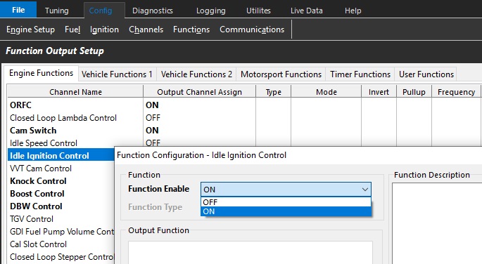
Select the control system and appropriate outputs via
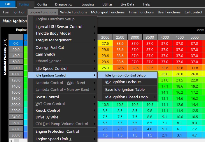
Config -> Function Setup -> Engine Functions -> Idle Ignition Control -> ON
Idle Ignition Control Setup
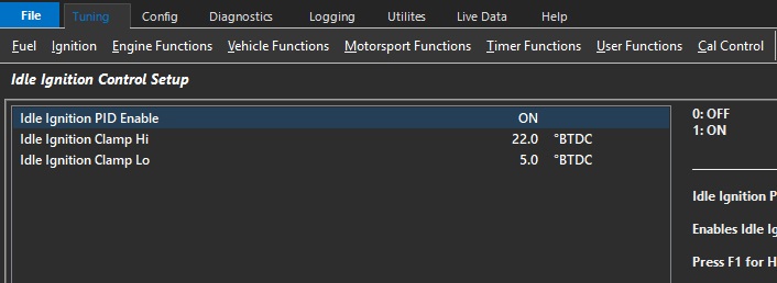
Idle Ignition PID Enable
Enables Idle Ignition closed loop PID. Without closed loop, the system will still reference the Base Idle Ignition Table (recommended ON).
- 0: OFF
- 1: ON
Idle Ignition Clamp Hi/Lo
Sets the minimum and maximum ignition angle the Idle Ignition Control can apply to the Base Timing setting.
Typical: 5 Deg (min), 22 Deg (max)
Idle Ignition Lockouts
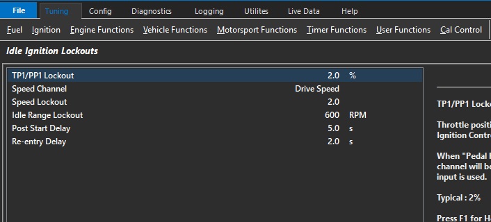
TP1/PP1 Lockout
Throttle position below which Idle Ignition Control can become active
When “Pedal Position 1” input is active this channel will be used. Otherwise ‘Throttle Position 1"input is used.
Typical : 2%
Speed Channel
Used to define how the “Speed Lockout” is used.
Speed inputs must be defined and properly calibrated under “Input Setup”
Speed Lockout
Locks out Idle Ignition Control when the speed is greater than or equal to this value (KPH).
Typical : 5.0
** Speed Channel must be defined.
Idle Range Lockout
The engine speed must fall below the Idle Target + Idle Range Lockout before Idle Ignition Control becomes active.
Example:
Idle Target = 800 (set from Idle Speed Control menu)
Idle Range Lockout = 400.
Idle Speed Control will become active when the engine speed falls below 1200 RPM.
Typical: 400 RPM
Post Start Delay
Delay after the engine speed has exceeded the crank exit RPM before Idle Ignition Control becomes active.
Typical : 2 sec
Re-entry Delay
Delay once all lockouts are cleared before Idle Ignition Control becomes active.
Base Idle Ignition Table
Defines the base ignition angle of the idle ignition control.
This table can be expanded into a 3D look up table using any runtime for axis.
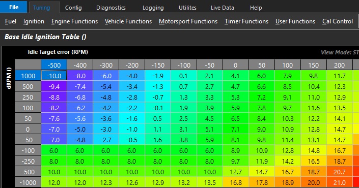
Above example shows the table spanned using Idle Target error & dRPM
- Idle Target error references Idle Speed Control Main Idle Target table
** dRPM is the engine Speed rate of change
Idle Ignition Closed Loop Contro
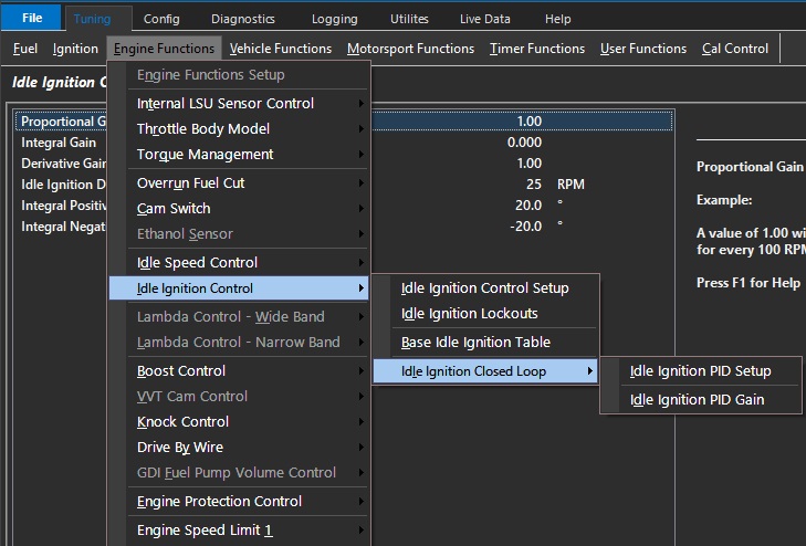
The Emtron ECU adds closed loop correction factors to Idle Speed Ignition functions.
This means it can added closed loop correction factors on top of the base idle ignition angle based on engine speed rate of change VS idle speed target.
Idle Ignition PID Setup
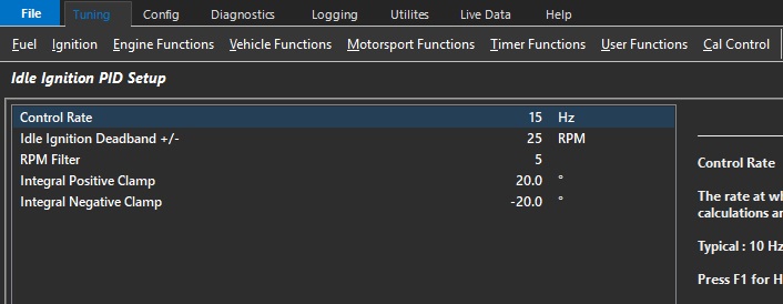
Control Rate
The frequency or rate at which the PID control algorithm calculations are performed.
Typical : 10 Hz
Idle Ignition Deadband +/-
The output control signal is held constant when the Input Signal (RPM) falls within the deadband range of the Setpoint (RPM Target). This helps reduce steady state error and oscillations.
Typical : 25 RPM
RPM Filter
Filters the RPM signal to allow better PID control
Typical : 5
Integral Positive/Negative Clamp
Allows the user to set the minimum and maximum Integral gain compensation used by the closed loop system.
Idle Ignition PID Gain
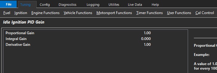
Proportional Gain
Proportional gain controls how aggressive instantaneous correction must be.
Integral Gain
Integral gain controls how much adaptive correction is needed.
Derivative Gain
Derivative gain controls predictive correction. This function is used to prevent overshooting targets by looking at a number of factors like rate of change, and P and I gain.