Allows the user to set the minimum and maximum deviation that can be used by the closed loop system.
These parameters can be expanded into a 3D look up tables to provide greater accuracy regarding closed loop control.
** These values are Duty Cycle when using a solenoid, Step counts if using a stepper motor, or Position if using DBW.
Idle Closed Loop Control
Idle Closed Loop Control
** For DBW, it is advised to use a PI control strategy (put D-Gain at zero). Also keep Idle PI Gains small.
See Plugin Sample Files for examples on these settings.
** For DBW, it is advised to use TMF mode for better closed loop control (see Idle Speed Tuning)
** If Idle Ignition Control is also ON, make sure the Idle Ignition I-Gain is set to zero so both Idle Ignition and Idle DBW systems are not fighting each other
Example : Do not have I-Gain active on both systems.
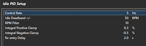
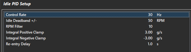
Idle PID Setup
Control Rate
The rate at which the PID control algorithm calculations are performed.
Typical : 10 Hz
Idle Deadband +/-
The output control signal is held constant when the Input Signal (RPM) falls within the deadband range of the Setpoint (Idle Target). This helps reduce steady state error and oscillations.
Typical : 20 RPM
RPM Filter
Filters the RPM signal to allow better PID control
Typical : 5
Integral Positive/Negative Clamp
Allows the user to set the minimum and maximum I gain compensation used by the closed loop system.
Re-entry Delay
Delay once all lockouts are cleared before Closed Loop Idle Control becomes active.
** Will immediately become active if engine speed falls below the Target RPM
Idle Speed Control Configuration (TMF)
This section assumes the DBW has been configured and operating correctly.
The following steps should be used to configure the Idle Speed control system to work using Throttle Mass Flow.
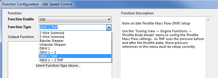
Configure the Throttle Mass Flow Idle Speed Control output function type using the menu:
Config -> Functions -> Function Output Setup -> Engine Functions Tab -> Idle Speed Control
Select either DBW 1 TMF or DBW 1 + 2 TMF
Configure the throttle body model using the menu: Tuning -> Engine Function -> Throttle Body Model -> Throttle Body Setup
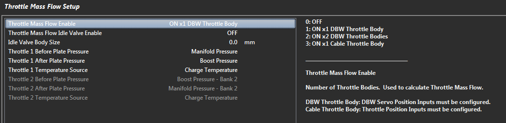
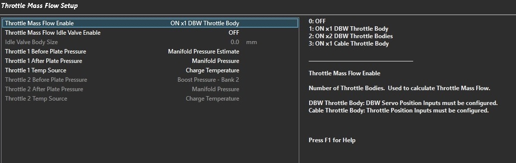
Configure the Throttle Mass Flow model using the menu: Tuning -> Engine Function -> Throttle Body Model -> Throttle Mass Flow Setup
Step 1- Select the throttle mass flow enable type that is applicable to your configuration. Example: ON x 1 DBW Throttle Body
TMF idle valve option is for TMF fuel model on cable throttle engines & is not applicable to DBW TMF idle speed control.
The TMF idle valve size input is also only applicable to cable throttle TMF applications
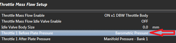
Step 2 - Set Throttle 1 before plate pressure source
If you intend to use TMF in areas other than idle, there should be a pressure sensor already fitted before the throttle plate and this should be selected.
Example: Boost Pressure Sensor

In the case of only wanting to achieve TMF Idle Speed Control and there is no sensor fitted before the plate, simply select the internal       Barometric Pressure sensor.

Other more complicated methods are also available for advanced users..
Step 3. Set the Throttle 1 After Plate Pressure source. This is normally the MAP sensor
Step 4. Set the Throttle 1 Temperature source. This is normally set to charge temperature
Repeat for Throttle 2 if applicable
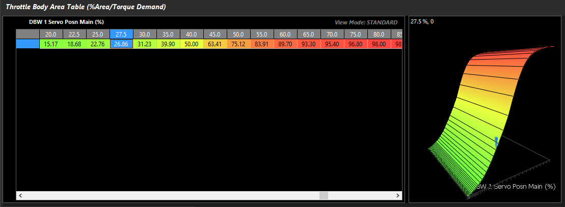
Throttle Body Area Table. See Throttle Body Setup help topic for more information
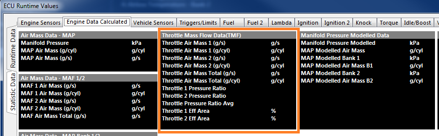
Confirm the Throttle Mass Flow calculations are operating, the data can be viewed from the Runtime menu (F3) -> Engine Data Calculated tab
Idle Speed Control Lockouts (TMF)
Idle speed control lockouts (TMF)
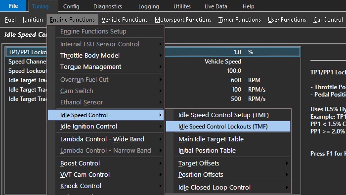
Tuning –> Engine Functions –> Idle Speed control –> Idle Speed Control lockouts (TMF)
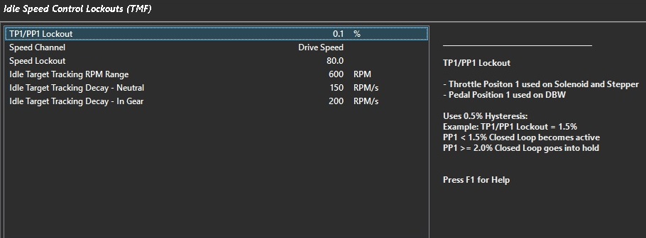
TP1/PP1 Lockout
For TMF idle speed control, this is a Pedal Position 1 lockout target.
This feature uses a 0.5% hysteresis in its application.
Example: TP1/PP1 Lockout = 1.5%
PP1 < 1.5% Closed Loop becomes active
PP1 >= 2.0% Closed Loop goes into hold.
A typical value is 0.5% Pedal Position
Speed Channel
Used to define how the “Speed Lockout” is used.
0: OFF
1: Drive Speed
2: Ground Speed
3: Drive Speed Front L
4: Drive Speed Front R
5: Drive Speed Rear L
6: Drive Speed Rear R
7: Undriven Speed Front L
8: Undriven Speed Front R
9: Undriven Speed Rear L
10: Undriven Speed Rear R
11: Front Axle Speed
12: Rear Axle Speed
13: Vehicle Speed
**** Speed inputs must be defined and properly calibrated under “Input Setup”**
Speed Lockout
Locks out Idle Speed Control when the speed is greater than or equal to this value (KPH).
A typical value is 5.0
Note: A Speed Channel must be defined to function
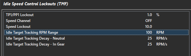
Idle Target Tracking RPM Range
The engine speed must fall to the Idle Target + Idle Target Tracking RPM Range. This is the rpm threshold for TMF idle speed control activation.
Example:
Idle Target rpm (Plus any Offsets applied) = 800
Idle Target Tracking RPM Range = 350
TMF Idle Speed Control will become active when the engine speed falls to equal 1150 RPM.
A typical vale is 350 RPM
Idle Target Tracking Decay – Neutral
This function sets the rate of decay to idle in rpm per second that the engine speed reduction is applied once the engine speed is within the Idle Target Tracking RPM Range and the transmission is regarded to be in Neutral
A typical value is 250 rpm/sec
Idle Target Tracking Decay – In Gear
This function sets the rate of decay to idle in rpm per second that the engine speed reduction is applied once the engine speed is within the Idle Target Tracking RPM Range and the transmission is regarded to be in Gear
A typical value is 250 rpm/sec
Idle Speed Control Lockouts
Idle Speed Lockouts
TP1/PP1 Lockout
% below in which Idle Speed Control system becomes active.
Throttle Position 1 used on Solenoid and Stepper systems
Pedal Position 1 used on DBW systems
Speed Channel
Used to define how the “Speed Lockout” is used.
0: OFF
1: Drive Speed
2: Ground Speed
3: Drive Speed Front L
4: Drive Speed Front R
5: Drive Speed Rear L
6: Drive Speed Rear R
7: Undriven Speed Front L
8: Undriven Speed Front R
9: Undriven Speed Rear L
10: Undriven Speed Rear R
11: Front Axle Speed
12: Rear Axle Speed
13: Vehicle Speed
** Speed inputs must be defined and properly calibrated under “Input Setup”
Speed Lockout
Locks out Idle Speed Control when the speed is greater than or equal to this value (KPH).
Typical : 5.0
** Speed Channel must be defined.
Idle Range Lockout
The engine speed must fall below the Idle Target + Idle Range Lockout before Idle Speed Control becomes active.
Example:
Idle Target = 800 (set from Idle Speed Control menu)
Idle Range Lockout = 400.
Idle Speed Control will become active when the engine speed falls below 1200 RPM.
Typical: 400 RPM
Idle Speed Control Setup (TMF)
Idle speed control Setup (TMF)
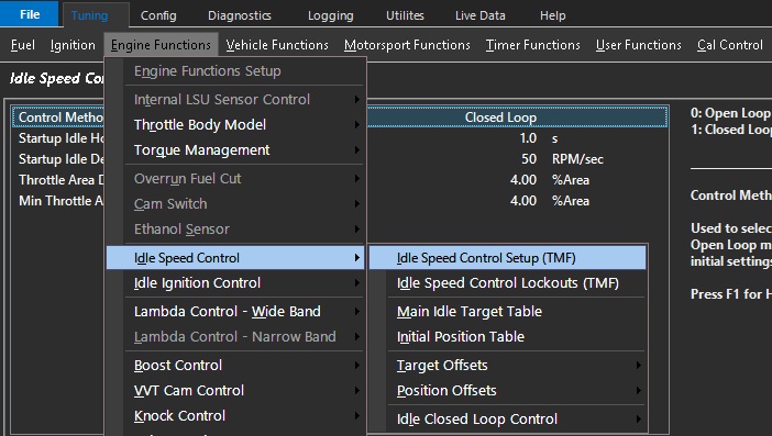
Tuning –> Engine Functions –> Idle Speed control –> Idle Speed Control setup (TMF)
Control method
Used to select either Open or Closed Loop.
Open Loop mode is generally used to setup initial settings before using Closed Loop mode.
0: Open Loop
1: Closed Loop
** Closed Loop applies PID functions to Idle Feed Forward
** Idle Feed Forward is derived from Idle Initial Position + any comp tables
Start-up idle hold time:
How long the ECU is required to remain at the predetermined flare rpm on start up.
Please note: The Initial position table when in open loop mode is just that, the initial position in g/s of airflow that the engine will target. Once closed loop TMF idle control is activated, the Idle Speed Control – Initial Position Table (g/s) becomes the feed forward table for TMF closed loop idle. It is no longer an initial position, rather it is an expected value that feeds into the TMF idle speed PID control strategy. The values to be set in this table are arrived at when using the TMF Idle speed control in Open Loop control much as one would with Open & Closed Loop Boost control (See Idle Speed Control – Initial Position Table (g/s)
Start-up idle decay rate:
This function sets the rate of decay to idle in rpm per second that engine speed reduction is applied; from the start up offset target rpm (Flare) to the idle target rpm once the engine is running and the start-up idle hold time has expired (See above)
Throttle area demand (idle) clamp:
The throttle area clamp is a safety feature that prevents the DBW servo from exceeding a set throttle body area percentage at idle and prevents unintended values when calibrating the function.
This value is directly related to the values previously imputed into the Throttle body area table
A typical value is 10% - this refers to 10% throttle area, not DBW servo position or TPS
See Throttle body set up – throttle body area table
Min Throttle area blend pedal to idle:
This is the threshold below which the Pedal Throttle Area Demand starts to blend
Open Loop mode is generally used to setup initial settings before using Closed Loop mode.
0: Open Loop
1: Closed Loop
** Closed Loop applies PID functions to Idle Feed Forward
** Idle Feed Forward is derived from Idle Initial Position + any comp tables
Startup Idle Hold Time
Time delay before idle speed control is active after startup
Startup Idle Decay Rate
Decay rate (in RPM/sec) after Startup Idle Hold Time expires
Stepper Direction
Used to set polarity of the stepper motor.
0: Normal
1: Reversed
Stepper Position Full Reset
Used to reset the stepper motor to its fully closed position. When set to ON the ECU will command the stepper motor to move 200 steps. Once complete the motor is returned to its default position.
This setting should be used on first installation when the position of the stepper motor is unknown.
Can be switched back to OFF at any time without effecting stepper motor operation.
0: OFF
1: ON
Stepper Reset
When set to Key-On the ECU will command the stepper motor to move 200 steps fully closed at Key-On.
Once completed the motor is returned to its default position.
The Key-OFF option requires the ECU EFI Relay control on be connected and working correctly (recommended).
0: Key-ON
1: Key-OFF
Idle Speed Control
Idle Speed Control
The following calculated run times are generated by Emtron that are Ide Speed Control related (to be further discussed more specifically):
Idle Target         –     Current Target Idle Speed

Idle Position        -    Current Live Idle Position

Idle Target Error         -     Error from Target Idle Speed

Idle Position Base     -     Base Position of Idle Speed (%/Steps)

Idle Position Flow Target    -     Flow Target when using Idle TMF mode (g/second)

Throttle Area - Idle     –     Idle Throttle Area %

Pedal Position 1        –     Pedal Position

Idle Target Offsets (grp)    –     Offsets to Idle Target (RPM)

Idle Comps (group)     –     Offsets to Idle Position (%/Steps)

Idle Status         –     Current status of Idle Speed Control

Idle PID Status        -    Status of Idle Speed Control Closed Loop PID

Idle P, I, and D        -    Proportional, Integral, and Derivative live data from Closed Loop

Idle Feed Forward    -    Feed forward position for Idle Speed Closed Loop Control
Idle Speed Control Function Setup
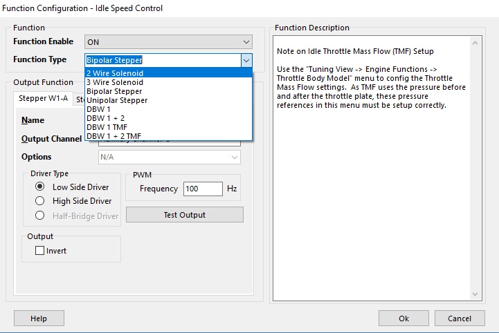
Emtron has eight methods of Idle Speed Control
Config, Function Setup, Idle Speed Control
2 Wire Idle Solenoid
Configure one output for control
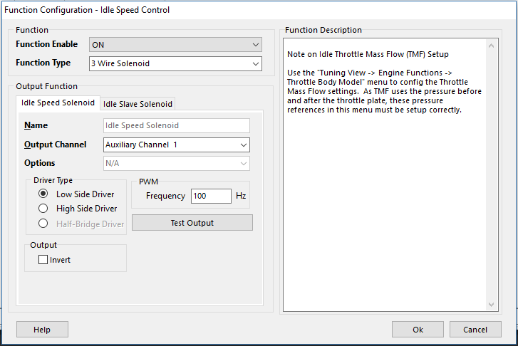
3 Wire Idle Solenoid
Configure two outputs for control (Main/Slave)
Bipolar Stepper
Configure four outputs for control
Unipolar Stepper
Configure four outputs for control
DBW 1
No outputs, as the function takes over DBW positioning (raw position)
DBW 1+2
No outputs, as the function takes over DBW 1+2 positioning (raw position)
DBW 1 TMF
No outputs, as the function takes over DBW positioning (Throttle Mass Flow target)
DBW 1+2 TMF
No outputs, as the function takes over DBW 1+2 positioning (Throttle Mass Flow target)
** Idle Throttle Mass Flow (TMF) Setup
Use the “Tuning View -> Engine Functions -> Throttle Body Model” menu to config the Throttle Mass Flow settings. As TMF uses the pressure before and after the throttle plate, these pressure references in this menu must be setup correctly. See Idle Speed Tuning
Idle Speed Tuning Guide
Idle Speed Tuning Guide
Idle Speed Tuning
Idle Speed Control in Emtune has comprehensive functions. There are a multiple tuning parameters, target, and position compensations.
Ignition timing is a contributing factor to engine idle speed. Please make sure you have reasonable timing being commanded by the ECU to make idle speed configuration go smoothly and function consistently.
** If planning to use idle ignition control, the static value for tuning idle speed should be in between the working range of the idle ignition control for both systems to be affective.
Commanding ignition timing off the main ignition table is recommended for first startup of an engine. The values in the main table can later be edited once functions (like Idle Ignition Control) are subsequently added.
Tuning Idle Speed Control
Regardless of the system being used, starting idle speed control in open loop is best.
Initial Position:
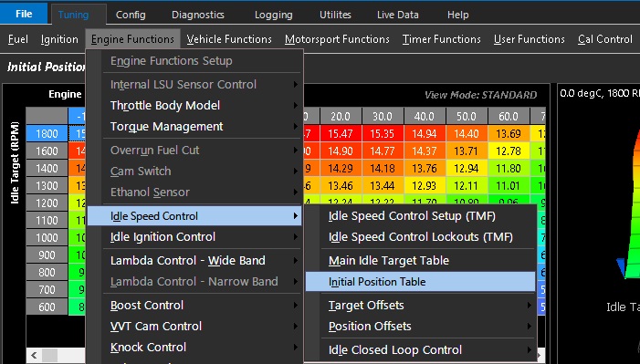
Tuning -> Engine Functions -> Idle Speed Control -> Initial Position Table
This is the feed forward position for the idle speed control.
The value in this table is constant regardless of idle speed lockouts, except if DBW or DBW TMF modes.
** Initial Position can always be compensated by Position Offsets
Idle speed is then locked out due to throttle position and engine speed (10%TP, 3000PRM)
Initial Position = 40%
Idle Position = 40% until lockouts are satisfied (engine rpm, TP, etc)
Units in this table vary depending on the Idle Speed Control method used,
IE - Stepper count for stepper motor, Duty cycle for solenoid, DBW position, or Target Throttle Mass Flow
It is recommended to configure one of the axes of the Initial Position table to an Idle Target Speed (Main Idle Target, see below).
Initial Position can be compensated several ways under:
Tuning -> Engine Functions -> Idle Speed Control -> Position Offsets
** Position compensations (comp tables) add/subtract to the initial position
** This is the feed forward if closed loop control is used
Main Idle Target:
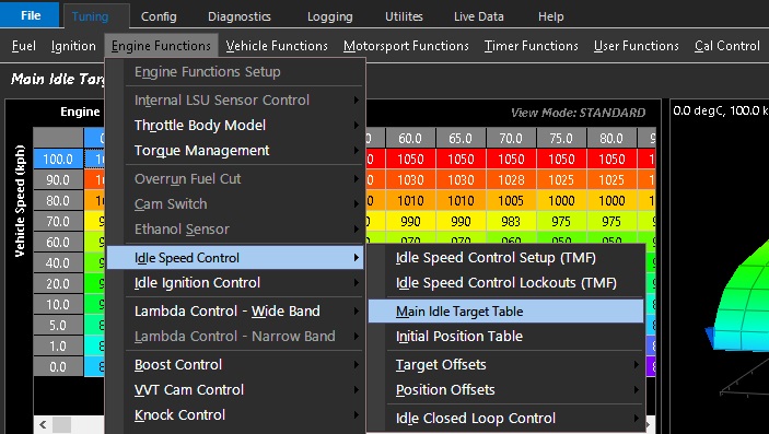
Tuning -> Engine Functions -> Idle Speed Control -> Main Idle Target Table
This table allows you to build an idle target speed in RPM
Like all Emtron tables, different runtimes are available for axis configuration making the system very flexible.
** This table is active if the Idle Ignition Control function is turned on as well.
Once you have a base set up for initial position and main idle target, match the initial position to target idle speed during different engine environmental conditions (most commonly engine temperature).
With this properly configured, going back to the Main Idle Target Table in different operating conditions should make the engine speed change and match the target accordingly.
** A good open loop configuration is the basis for enabling Closed Loop Control.
Main Idle Target can be adjusted by several offset tables under:
Depending on the system being used, closed loop settings will vary. Basic PID tuning principles apply.
See specific examples below for notes on individual systems regarding Closed Loop (when applicable)
2 Wire Idle Solenoid
A Two Wire Idle solenoid is generally supplied power and the ECU Aux Output pulse the other pin to open the valve.
Units in position tables are in %Duty
Typical frequencies for 2 Wire Idle Solenoids are 50-250hz
Closed loop:
2 Wire Idle Solenoids often have a default air bleed position when they are not powered (failure position). The min and max deviation from the initial position when using closed loop must be carefully configured so the idle valve does not fall into those ranges while the engine is running. Otherwise the idle engine speed will not be able to be controlled.
Example:
0-20% = default position air/bleed. At 0% (same as being powered off), the idle valve is flowing air through the mechanical default air bleed to prevent engine stall. It then closes completely at 20%.
20-100% re-opens the idle valve with precision. This is the range the ECU must operate in for good idle speed control.
3 Wire Idle Solenoid
A 3 Wire Idle solenoid is generally supplied power from the EFI Relay circuit and the ECU Aux Outputs pulse the second and third extra pins to open and close the valve.
The Idle Speed Solenoid output should be the opening winding.
The Idle Slave Solenoid output should be the closing winding.
Units in position tables are in %Duty
The ECU mirrors the opposite of the opening duty on the slave channel (closing wining), providing more accurate open loop positioning vs 2 wire idle solenoids.
IE –
Idle Speed Solenoid Output 75%
Idle Slave Solenoid Output 25%
Idle Speed Solenoid Output 30%
Idle Slave Solenoid Output 70%
The frequency of the valve is configured in output setup (See Idle Speed Setup).
Typical frequencies for 3 Wire Idle Solenoids are 50-250hz
Bi-Polar/Uni-Polar Stepper Motor
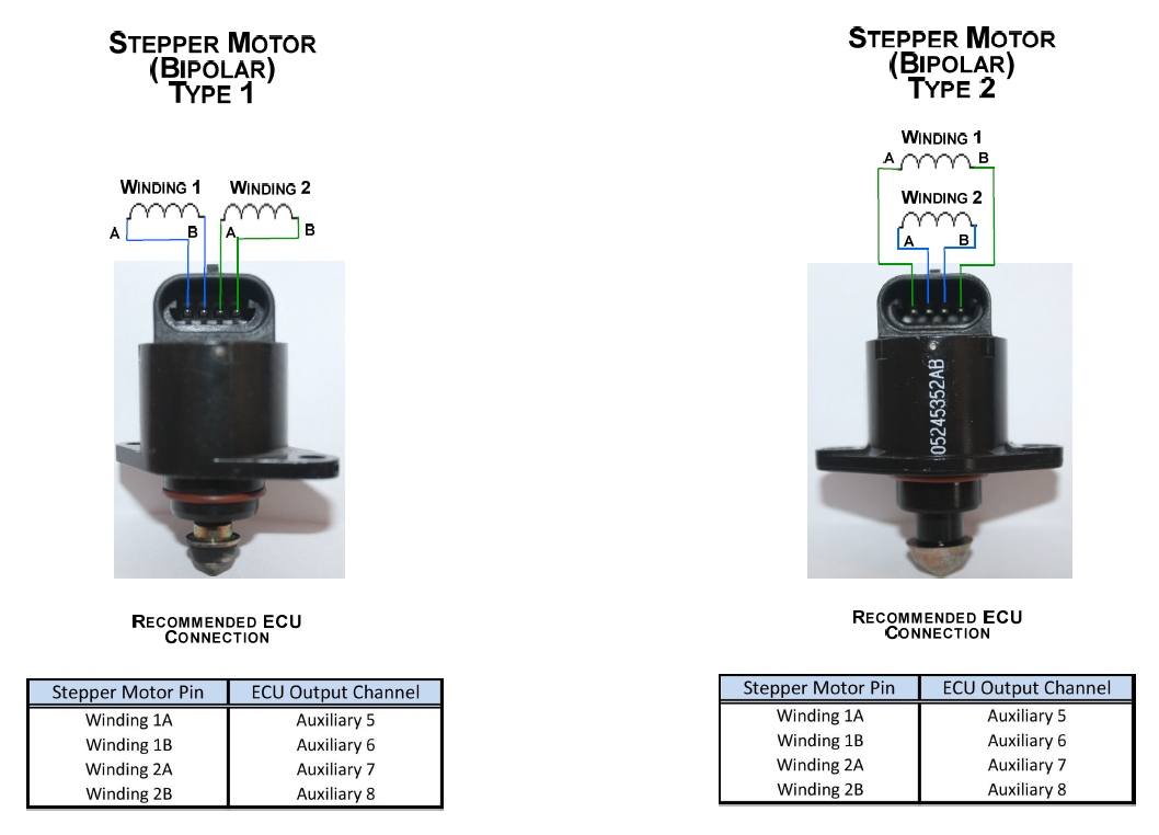
DC Stepper Motors convert rotation into step counts which the ECU can move incrementally to change the amount of air bleeding around the closed throttle. See wiring guides regarding wiring different types of stepper motors.
Units in position tables are in Steps from Closed position
** Stepper Valves have extra settings such as “Closed position is reset either at Key On/Off” under:
Tuning -> Engine Functions -> Idle Speed Control -> Idle Speed Control Setup
DBW (1, 1 + 2)
When set to DBW 1, or DBW 1+2, the ECU will use the DBW motor position to control idle speed of the engine.
Units in position tables are in raw DBW position.
** DBW Control must be fully configured
** DBW PID must be set up accurately to ensure precision during Idle Speed due to the air flow being very sensitive to airflow vs DBW position (especially with a large throttle body).
Setting Initial Position Table
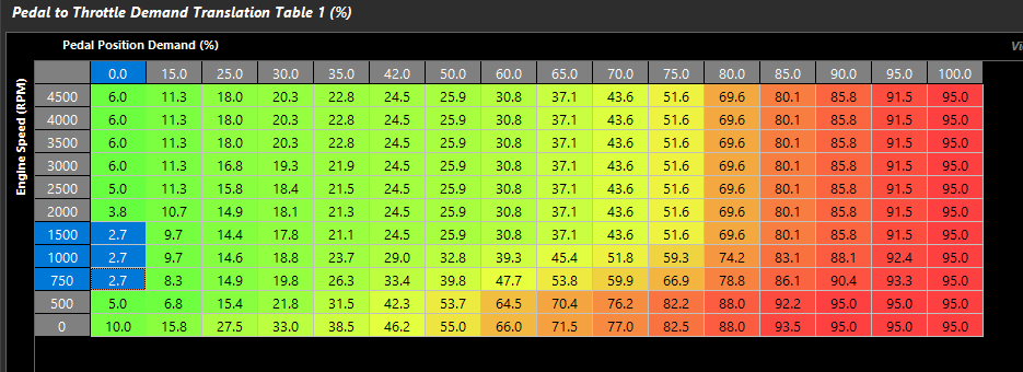
A good way to initially set up DBW motor position is recommended to lockout idle speed completely and work off the Pedal to Throttle Demand Table:
Once the engine is idling at the appropriate RPM, use Runtimes to look at what the raw DBW position/Throttle Position to populate the Initial Position Table.
Initial Position built off above examples at operating temperature. Estimation for extra air flow can be extrapolated regarding colder temps and blended as shown (must be checked on cold start).
** Position is much more sensitive to air flow than solenoids or stepper motors
Transitioning smoothly from Idle Speed to Pedal Demand
Because the Idle Speed Control Initial Position is controlling the DBW target, when the idle speed control is locked out (pedal is pushed), the DBW target will transition back into the Pedal to Throttle Demand Table. It is important to have a minimum position that corresponds to somewhere close to the idle Initial Position. If 0% (or a lower number than Idle Initial Position) is targeted in the Pedal Demand Table, the engine may stall/stumble due to lack of airflow.
Initial Position Highlighted
Pedal Demand Highlighted
** Throttle Body Area Table is 1:1 in this example
** If Throttle Body Area is worked out, then Pedal to Throttle Demand Translation Table will not match DBW initial position, and the raw position needed will need to be matched vs Throttle Body Area
** If Throttle Body Area Table is worked out, then Idle Speed Control mode should be DBW 1/1 + 2 TMF
Closed loop:
Using Closed Loop Control with DBW Idle Speed Control (%TP/%DBW Servo Posn) requires much less aggressive PID settings and limits. The reason for this is only a small change to the DBW position is needed to make a large affect on airflow.
For initial setup use the following PID settings:
Proportional Gain Table = 0.00
Integral Gain Table = 0.025
Derivative Gain Table = 0.00
Min/Max Deviation from Initial Position Table = +/- 1%
The above settings will limit how quickly the Closed Loop will change the initial position, and limit how far the throttle can be moved from the initial position.
** Final settings will probably have less minimum deviation than max deviation for Anti-Stall functions
Idle Speed Tuning Guide
Idle Speed Tuning Guide
Idle Speed Tuning
Idle Speed Control in Emtune has comprehensive functions. There are a multiple tuning parameters, target, and position compensations.
Ignition timing is a contributing factor to engine idle speed. Please make sure you have reasonable timing being commanded by the ECU to make idle speed configuration go smoothly and function consistently.
** If planning to use idle ignition control, the static value for tuning idle speed should be in between the working range of the idle ignition control for both systems to be affective.
Commanding ignition timing off the main ignition table is recommended for first startup of an engine. The values in the main table can later be edited once functions (like Idle Ignition Control) are subsequently added.
Tuning Idle Speed Control
Regardless of the system being used, starting idle speed control in open loop is best.
Initial Position:
Tuning -> Engine Functions -> Idle Speed Control -> Initial Position Table
This is the feed forward position for the idle speed control.
The value in this table is constant regardless of idle speed lockouts, except if DBW or DBW TMF modes.
** Initial Position can always be compensated by Position Offsets
Idle speed is then locked out due to throttle position and engine speed (10%TP, 3000PRM)
Initial Position = 40%
Idle Position = 40% until lockouts are satisfied (engine rpm, TP, etc)
Units in this table vary depending on the Idle Speed Control method used,
IE - Stepper count for stepper motor, Duty cycle for solenoid, DBW position, or Target Throttle Mass Flow
It is recommended to configure one of the axes of the Initial Position table to an Idle Target Speed (Main Idle Target, see below).
Initial Position can be compensated several ways under:
Tuning -> Engine Functions -> Idle Speed Control -> Position Offsets
** Position compensations (comp tables) add/subtract to the initial position
** This is the feed forward if closed loop control is used
Main Idle Target:
Tuning -> Engine Functions -> Idle Speed Control -> Main Idle Target Table
This table allows you to build an idle target speed in RPM
Like all Emtron tables, different runtimes are available for axis configuration making the system very flexible.
** This table is active if the Idle Ignition Control function is turned on as well.
Once you have a base set up for initial position and main idle target, match the initial position to target idle speed during different engine environmental conditions (most commonly engine temperature).
With this properly configured, going back to the Main Idle Target Table in different operating conditions should make the engine speed change and match the target accordingly.
** A good open loop configuration is the basis for enabling Closed Loop Control.
Main Idle Target can be adjusted by several offset tables under:
Depending on the system being used, closed loop settings will vary. Basic PID tuning principles apply.
See specific examples below for notes on individual systems regarding Closed Loop (when applicable)
2 Wire Idle Solenoid
A Two Wire Idle solenoid is generally supplied power and the ECU Aux Output pulse the other pin to open the valve.
Units in position tables are in %Duty
Typical frequencies for 2 Wire Idle Solenoids are 50-250hz
Closed loop:
2 Wire Idle Solenoids often have a default air bleed position when they are not powered (failure position). The min and max deviation from the initial position when using closed loop must be carefully configured so the idle valve does not fall into those ranges while the engine is running. Otherwise the idle engine speed will not be able to be controlled.
Example:
0-20% = default position air/bleed. At 0% (same as being powered off), the idle valve is flowing air through the mechanical default air bleed to prevent engine stall. It then closes completely at 20%.
20-100% re-opens the idle valve with precision. This is the range the ECU must operate in for good idle speed control.
3 Wire Idle Solenoid
A 3 Wire Idle solenoid is generally supplied power from the EFI Relay circuit and the ECU Aux Outputs pulse the second and third extra pins to open and close the valve.
The Idle Speed Solenoid output should be the opening winding.
The Idle Slave Solenoid output should be the closing winding.
Units in position tables are in %Duty
The ECU mirrors the opposite of the opening duty on the slave channel (closing wining), providing more accurate open loop positioning vs 2 wire idle solenoids.
IE –
Idle Speed Solenoid Output 75%
Idle Slave Solenoid Output 25%
Idle Speed Solenoid Output 30%
Idle Slave Solenoid Output 70%
The frequency of the valve is configured in output setup (See Idle Speed Setup).
Typical frequencies for 3 Wire Idle Solenoids are 50-250hz
Bi-Polar/Uni-Polar Stepper Motor
DC Stepper Motors convert rotation into step counts which the ECU can move incrementally to change the amount of air bleeding around the closed throttle. See wiring guides regarding wiring different types of stepper motors.
Units in position tables are in Steps from Closed position
** Stepper Valves have extra settings such as “Closed position is reset either at Key On/Off” under:
Tuning -> Engine Functions -> Idle Speed Control -> Idle Speed Control Setup
DBW (1, 1 + 2)
When set to DBW 1, or DBW 1+2, the ECU will use the DBW motor position to control idle speed of the engine.
Units in position tables are in raw DBW position.
** DBW Control must be fully configured
** DBW PID must be set up accurately to ensure precision during Idle Speed due to the air flow being very sensitive to airflow vs DBW position (especially with a large throttle body).
Setting Initial Position Table
A good way to initially set up DBW motor position is recommended to lockout idle speed completely and work off the Pedal to Throttle Demand Table:
Once the engine is idling at the appropriate RPM, use Runtimes to look at what the raw DBW position/Throttle Position to populate the Initial Position Table.
Initial Position built off above examples at operating temperature. Estimation for extra air flow can be extrapolated regarding colder temps and blended as shown (must be checked on cold start).
** Position is much more sensitive to air flow than solenoids or stepper motors
Transitioning smoothly from Idle Speed to Pedal Demand
Because the Idle Speed Control Initial Position is controlling the DBW target, when the idle speed control is locked out (pedal is pushed), the DBW target will transition back into the Pedal to Throttle Demand Table. It is important to have a minimum position that corresponds to somewhere close to the idle Initial Position. If 0% (or a lower number than Idle Initial Position) is targeted in the Pedal Demand Table, the engine may stall/stumble due to lack of airflow.
Initial Position Highlighted
Pedal Demand Highlighted
** Throttle Body Area Table is 1:1 in this example
** If Throttle Body Area is worked out, then Pedal to Throttle Demand Translation Table will not match DBW initial position, and the raw position needed will need to be matched vs Throttle Body Area
** If Throttle Body Area Table is worked out, then Idle Speed Control mode should be DBW 1/1 + 2 TMF
Closed loop:
Using Closed Loop Control with DBW Idle Speed Control (%TP/%DBW Servo Posn) requires much less aggressive PID settings and limits. The reason for this is only a small change to the DBW position is needed to make a large affect on airflow.
For initial setup use the following PID settings:
Proportional Gain Table = 0.00
Integral Gain Table = 0.025
Derivative Gain Table = 0.00
Min/Max Deviation from Initial Position Table = +/- 1%
The above settings will limit how quickly the Closed Loop will change the initial position, and limit how far the throttle can be moved from the initial position.
** Final settings will probably have less minimum deviation than max deviation for Anti-Stall functions
DBW (1 TMF, 1 + 2 TMF)
When set to DBW 1 TMF, or DBW 1+2 TMF, the ECU will use the DBW motor position to control idle speed of the engine based on a target Throttle Mass Flow of air. For DBW applications, this function is superior to any other type of idle speed control, especially with the closed loop function.
Units in position tables are in raw grams per second (g/s).
** DBW Control must be fully configured
** DBW PID must be set up accurately to ensure precision during Idle Speed due to the air flow being very sensitive to airflow vs DBW position (especially with a large throttle body).
Setting Initial Position Table
Since Throttle Mass Flow is the target, The Throttle Body Area table must be configured in the Throttle Body Model. Because that function needs to be tuned previously, setting the throttle target at a static number, or using regular DBW Idle Speed mode to get the engine running/idling may be a good start.
Tuning -> Engine Functions -> Throttle Body Model -> Throttle Body Area Table
Once the throttle area is worked out (see Throttle Mass Flow), the ECU will generate Throttle Mass Flow runtimes.
This is the expected airflow in g/s for the engine at a given idle rpm & temperature. A channel Air Mass Final – Flow g/s, generates the actual airflow consumed by the engine.
Use this runtime to help set the values in this table. The more accurate this table is, the better the closed loop idle control will function
Transitioning smoothly from Idle Speed to Pedal Demand
Because the Idle Speed Control is targeting a Throttle Mass Flow, the transition to Pedal Demand is much easier.
** Works best if Throttle Area is correct
Idle Target Tracking RPM Range and Decay
Tuning -> Engine Functions -> Idle Speed Control -> Idle Speed Control Lockouts (TMF)
When using TMF for Idle Speed Control, some extra settings are available to make the Idle Speed Control even more flexible.
Idle Target Tracking RPM Range raises the idle target when locked out until the Idle Speed Lockouts are satisfied again. This adds somewhat of a “dashpot” function to the system as if your Target Mass Flow is RPM based (like the above example), the Idle Speed will go to the Idle Speed Target PLUS the Target Tracking RPM.
Idle Target Tracking Decay then subsequently removes the Target Tracking Range in RPM/second
Good staring numbers are as follows:
Idle Target Tracking RPM Range = 100
Idle Target Tracking Decay = 25
Closed loop:
TMF Closed Loop control is superior to standard DBW Position Idle Control due to higher resolution targeting Mass Flow vs small DBW position changes.
For initial setup use the following PID settings:
Proportional Gain Table = 0.50
Integral Gain Table = 0.050
Derivative Gain Table = 0.25
Min/Max Deviation from Initial Position Table = +/- 3.00g/s
Idle Speed Tuning Guide
Idle Speed Tuning Guide
Idle Speed Tuning
Idle Speed Control in Emtune has comprehensive functions. There are a multiple tuning parameters, target, and position compensations.
Ignition timing is a contributing factor to engine idle speed. Please make sure you have reasonable timing being commanded by the ECU to make idle speed configuration go smoothly and function consistently.
** If planning to use idle ignition control, the static value for tuning idle speed should be in between the working range of the idle ignition control for both systems to be affective.
Commanding ignition timing off the main ignition table is recommended for first startup of an engine. The values in the main table can later be edited once functions (like Idle Ignition Control) are subsequently added.
Tuning Idle Speed Control
Regardless of the system being used, starting idle speed control in open loop is best.
Initial Position:
Tuning -> Engine Functions -> Idle Speed Control -> Initial Position Table
This is the feed forward position for the idle speed control.
The value in this table is constant regardless of idle speed lockouts, except if DBW or DBW TMF modes.
** Initial Position can always be compensated by Position Offsets
Idle speed is then locked out due to throttle position and engine speed (10%TP, 3000PRM)
Initial Position = 40%
Idle Position = 40% until lockouts are satisfied (engine rpm, TP, etc)
Units in this table vary depending on the Idle Speed Control method used,
IE - Stepper count for stepper motor, Duty cycle for solenoid, DBW position, or Target Throttle Mass Flow
It is recommended to configure one of the axes of the Initial Position table to an Idle Target Speed (Main Idle Target, see below).
Initial Position can be compensated several ways under:
Tuning -> Engine Functions -> Idle Speed Control -> Position Offsets
** Position compensations (comp tables) add/subtract to the initial position
** This is the feed forward if closed loop control is used
Main Idle Target:
Tuning -> Engine Functions -> Idle Speed Control -> Main Idle Target Table
This table allows you to build an idle target speed in RPM
Like all Emtron tables, different runtimes are available for axis configuration making the system very flexible.
** This table is active if the Idle Ignition Control function is turned on as well.
Once you have a base set up for initial position and main idle target, match the initial position to target idle speed during different engine environmental conditions (most commonly engine temperature).
With this properly configured, going back to the Main Idle Target Table in different operating conditions should make the engine speed change and match the target accordingly.
** A good open loop configuration is the basis for enabling Closed Loop Control.
Main Idle Target can be adjusted by several offset tables under:
Depending on the system being used, closed loop settings will vary. Basic PID tuning principles apply.
See specific examples below for notes on individual systems regarding Closed Loop (when applicable)
2 Wire Idle Solenoid
A Two Wire Idle solenoid is generally supplied power and the ECU Aux Output pulse the other pin to open the valve.
Units in position tables are in %Duty
Typical frequencies for 2 Wire Idle Solenoids are 50-250hz
Closed loop:
2 Wire Idle Solenoids often have a default air bleed position when they are not powered (failure position). The min and max deviation from the initial position when using closed loop must be carefully configured so the idle valve does not fall into those ranges while the engine is running. Otherwise the idle engine speed will not be able to be controlled.
Example:
0-20% = default position air/bleed. At 0% (same as being powered off), the idle valve is flowing air through the mechanical default air bleed to prevent engine stall. It then closes completely at 20%.
20-100% re-opens the idle valve with precision. This is the range the ECU must operate in for good idle speed control.
3 Wire Idle Solenoid
A 3 Wire Idle solenoid is generally supplied power from the EFI Relay circuit and the ECU Aux Outputs pulse the second and third extra pins to open and close the valve.
The Idle Speed Solenoid output should be the opening winding.
The Idle Slave Solenoid output should be the closing winding.
Units in position tables are in %Duty
The ECU mirrors the opposite of the opening duty on the slave channel (closing wining), providing more accurate open loop positioning vs 2 wire idle solenoids.
IE –
Idle Speed Solenoid Output 75%
Idle Slave Solenoid Output 25%
Idle Speed Solenoid Output 30%
Idle Slave Solenoid Output 70%
The frequency of the valve is configured in output setup (See Idle Speed Setup).
Typical frequencies for 3 Wire Idle Solenoids are 50-250hz
Bi-Polar/Uni-Polar Stepper Motor
DC Stepper Motors convert rotation into step counts which the ECU can move incrementally to change the amount of air bleeding around the closed throttle. See wiring guides regarding wiring different types of stepper motors.
Units in position tables are in Steps from Closed position
** Stepper Valves have extra settings such as “Closed position is reset either at Key On/Off” under:
Tuning -> Engine Functions -> Idle Speed Control -> Idle Speed Control Setup
DBW (1, 1 + 2)
When set to DBW 1, or DBW 1+2, the ECU will use the DBW motor position to control idle speed of the engine.
Units in position tables are in raw DBW position.
** DBW Control must be fully configured
** DBW PID must be set up accurately to ensure precision during Idle Speed due to the air flow being very sensitive to airflow vs DBW position (especially with a large throttle body).
Setting Initial Position Table
A good way to initially set up DBW motor position is recommended to lockout idle speed completely and work off the Pedal to Throttle Demand Table:
Once the engine is idling at the appropriate RPM, use Runtimes to look at what the raw DBW position/Throttle Position to populate the Initial Position Table.
Initial Position built off above examples at operating temperature. Estimation for extra air flow can be extrapolated regarding colder temps and blended as shown (must be checked on cold start).
** Position is much more sensitive to air flow than solenoids or stepper motors
Transitioning smoothly from Idle Speed to Pedal Demand
Because the Idle Speed Control Initial Position is controlling the DBW target, when the idle speed control is locked out (pedal is pushed), the DBW target will transition back into the Pedal to Throttle Demand Table. It is important to have a minimum position that corresponds to somewhere close to the idle Initial Position. If 0% (or a lower number than Idle Initial Position) is targeted in the Pedal Demand Table, the engine may stall/stumble due to lack of airflow.
Initial Position Highlighted
Pedal Demand Highlighted
** Throttle Body Area Table is 1:1 in this example
** If Throttle Body Area is worked out, then Pedal to Throttle Demand Translation Table will not match DBW initial position, and the raw position needed will need to be matched vs Throttle Body Area
** If Throttle Body Area Table is worked out, then Idle Speed Control mode should be DBW 1/1 + 2 TMF
Closed loop:
Using Closed Loop Control with DBW Idle Speed Control (%TP/%DBW Servo Posn) requires much less aggressive PID settings and limits. The reason for this is only a small change to the DBW position is needed to make a large affect on airflow.
For initial setup use the following PID settings:
Proportional Gain Table = 0.00
Integral Gain Table = 0.025
Derivative Gain Table = 0.00
Min/Max Deviation from Initial Position Table = +/- 1%
The above settings will limit how quickly the Closed Loop will change the initial position, and limit how far the throttle can be moved from the initial position.
** Final settings will probably have less minimum deviation than max deviation for Anti-Stall functions
DBW (1 TMF, 1 + 2 TMF)
When set to DBW 1 TMF, or DBW 1+2 TMF, the ECU will use the DBW motor position to control idle speed of the engine based on a target Throttle Mass Flow of air. For DBW applications, this function is superior to any other type of idle speed control, especially with the closed loop function.
Units in position tables are in raw grams per second (g/s).
** DBW Control must be fully configured
** DBW PID must be set up accurately to ensure precision during Idle Speed due to the air flow being very sensitive to airflow vs DBW position (especially with a large throttle body).
Setting Initial Position Table
Since Throttle Mass Flow is the target, The Throttle Body Area table must be configured in the Throttle Body Model. Because that function needs to be tuned previously, setting the throttle target at a static number, or using regular DBW Idle Speed mode to get the engine running/idling may be a good start.
Tuning -> Engine Functions -> Throttle Body Model -> Throttle Body Area Table
Once the throttle area is worked out (see Throttle Mass Flow), the ECU will generate Throttle Mass Flow runtimes.
This is the expected airflow in g/s for the engine at a given idle rpm & temperature. A channel Air Mass Final – Flow g/s, generates the actual airflow consumed by the engine.
Use this runtime to help set the values in this table. The more accurate this table is, the better the closed loop idle control will function
Transitioning smoothly from Idle Speed to Pedal Demand
Because the Idle Speed Control is targeting a Throttle Mass Flow, the transition to Pedal Demand is much easier.
** Works best if Throttle Area is correct
Idle Target Tracking RPM Range and Decay
Tuning -> Engine Functions -> Idle Speed Control -> Idle Speed Control Lockouts (TMF)
When using TMF for Idle Speed Control, some extra settings are available to make the Idle Speed Control even more flexible.
Idle Target Tracking RPM Range raises the idle target when locked out until the Idle Speed Lockouts are satisfied again. This adds somewhat of a “dashpot” function to the system as if your Target Mass Flow is RPM based (like the above example), the Idle Speed will go to the Idle Speed Target PLUS the Target Tracking RPM.
Idle Target Tracking Decay then subsequently removes the Target Tracking Range in RPM/second
Good staring numbers are as follows:
Idle Target Tracking RPM Range = 100
Idle Target Tracking Decay = 25
Closed loop:
TMF Closed Loop control is superior to standard DBW Position Idle Control due to higher resolution targeting Mass Flow vs small DBW position changes.
For initial setup use the following PID settings:
Proportional Gain Table = 0.50
Integral Gain Table = 0.050
Derivative Gain Table = 0.25
Min/Max Deviation from Initial Position Table = +/- 3.00g/s
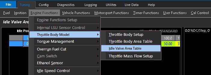
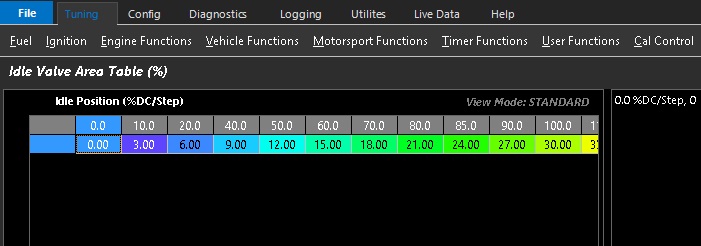
Idle Valve Area Table
Idle Valve Area Table %
Tuning –> Engine Functions –> Throttle Body Model –> Idle Valve Area Table %
When Throttle Mass Flow is utilized without a DBW throttle - I.E: 3: ON x1 Cable Throttle Body
The area of the idle valve needs to be accounted for in the TMF calculation.
The Idle Valve Area Table % allows setting & adjustment of the correlation between Idle Valve Area and the Idle valve step position or duty cycle. These values then feed into the airmass calculation and add to the Throttle Area Demanded and Throttle Effective Area
The table is user generated & should be verified for accuracy.
Method 1 – MAF verification
If the application is using a calibrated MAF sensor. Then the idle valve area % can be adjusted and matched to TMF air mass VS MAF air mass at different idle air control valve step positions/duty cycle.
Method 2 – Matching Lambda
If no MAF sensor is available, setting fuel trims to 0 (or near 0), you can adjust the idle valve area to match the target mixture very quickly
(throttle area verification required prior to these steps)
** The only way to truly validate error in the TMF calculation is to use Method 1
** Some extreme applications where live Lambda is unstable may be more difficult to map with Method 2
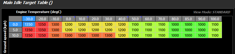
Main Idle Target Table
Main Idle Target Table
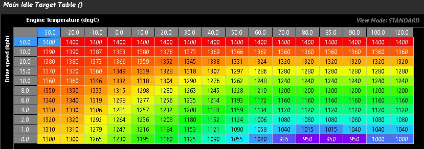
This look up table tells the ECU the desired RPM target for Idle Speed Control.
Above example shows the table spanned in 3D using Engine Temperature and Ground speed as axis.
** This target table is also used for Idle Ignition Control
Main Idle Target Table
Main Idle Target Table
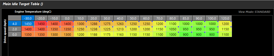
This look up table tells the ECU the desired RPM target for Idle Speed Control.
Above example shows the table spanned in 3D using Engine Temperature and Drive speed as the axis.
**** This target table is also used for Idle Ignition Control ****
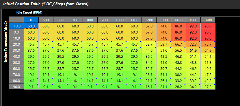
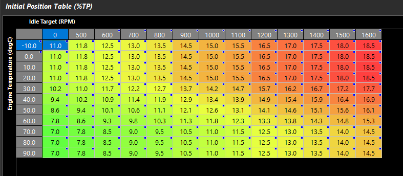
Initial Position Table
Initial Position Table
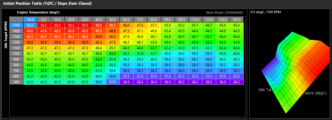
This look up table defines the base position of the idle speed control valve.
If a 2 or 3 wire Idle Solenoid is used, then this a base duty cycle to define position.
Units = % Duty Cycle
If a stepper motor, these are step counts from the closed position.
Units = Step Count
If DBW, this is a feed forward table for the electronic throttle positioning.
Units = Drive By Wire Servo Position
If DBW TMF, this is a feed forward table for air flow in g/s for the electronic throttle positioning.
Units = Throttle Mass Flow g/s
** Recommended Axis Configuration is Engine Temp vs Idle Speed Target for Closed Loop control\
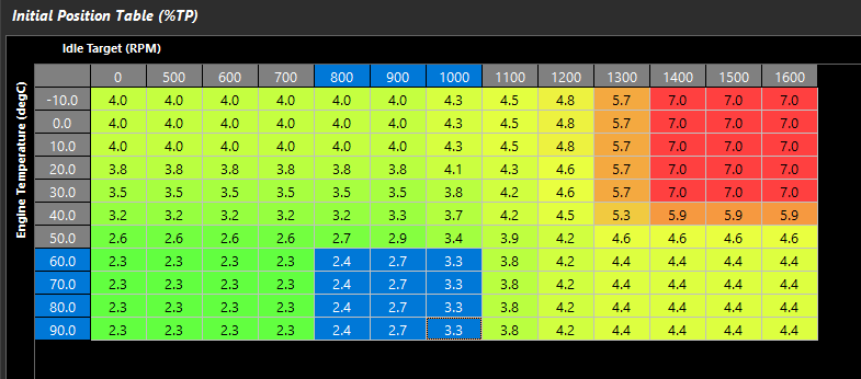
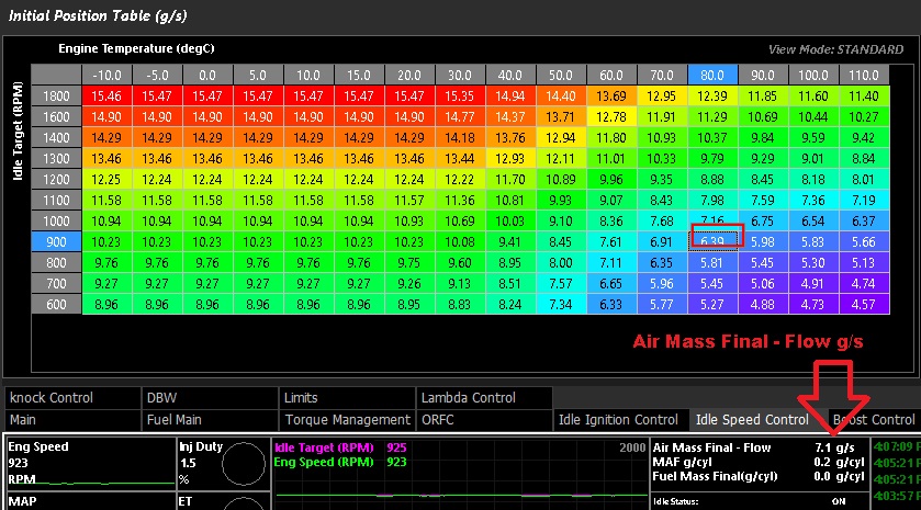
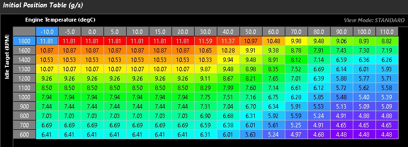
Initial Position Table g/s
Initial Position Table (g/s)
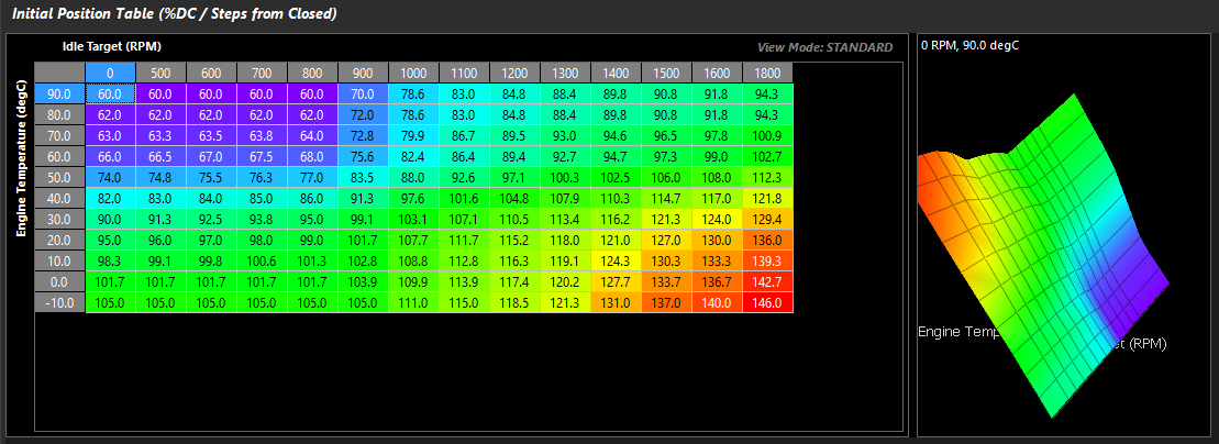
This is a feed forward table for air flow in g/s for the electronic throttle positioning.
Units = Throttle Mass Flow g/s
Above example shows the table spanned in 3D using Engine Temperature and Idle target RPM as the axis.
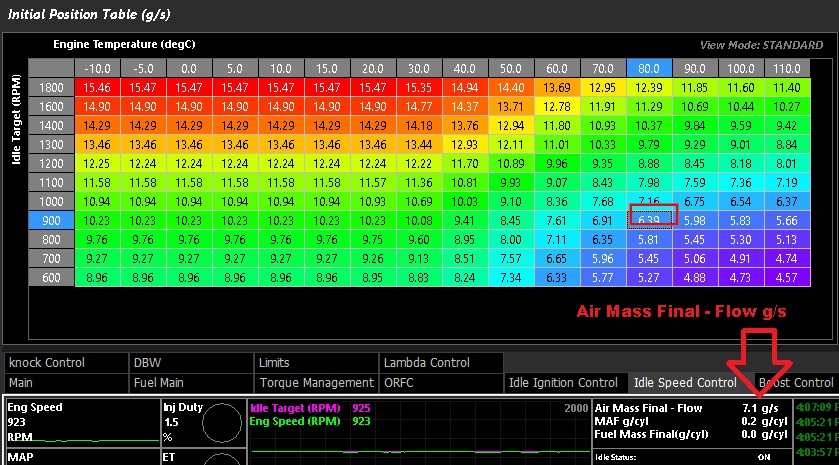
 **Tuning Tip**: As a feed forward table, this is the expected airflow in g/s for the engine at a given idle rpm & temperature.

                             The actual airflow consumed by the engine is found in the Air Mass Final – Flow g/s runtime.

                             Use this runtime to help 1Nsigh7set the values in this table.

                             The more accurate this table is, the better the closed loop idle control will function

                             See the example given below
The above example shows a typical R35 Nissan GTR Initial Position table g/s and how this correlates to the Air Mass Final value
Integral Gain Table
Integral Gain Table
Integral gain controls how much adaptive correction is needed.
This parameter can be expanded into a 3D look up table to provide greater accuracy regarding closed loop control.
I is Gain * 0.01 *Idle Target Error to convert to g/s added – counts/increments with the control frequency
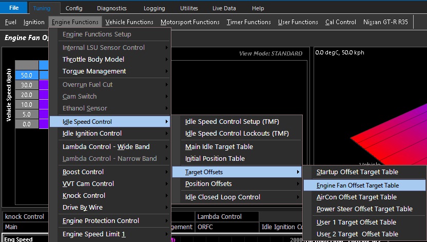
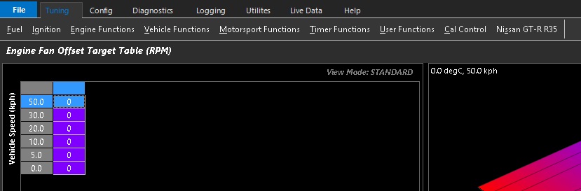
Engine Fan Offset Target Table
Engine Fan Offset Target Table
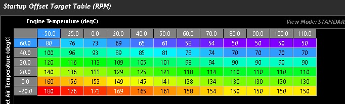
Startup Offset Target Table
Start-up Target Offset Table
Start-up offset works in conjunction with Start-up Idle Hold Time, and Start-up Idle Decay Rate under Idle Speed Control Setup
The above example is spanned in 3D using intake air temperature and Engine Temperature
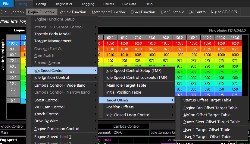
Target Offsets
Target Offsets
Offset Target Tables
Allows the user to define a target change to the Main Idle Target table (RPM) during the specified functions:
Startup offset works in conjunction with Startup Idle Hold Time, and Startup Idle Decay Rate under Idle Speed Control Setup
These tables can be expanded into a 3D look up table using any runtime for the axis.\
** These values offset RPM units
Target Offsets are specific tables and 2 additional user definable tables.
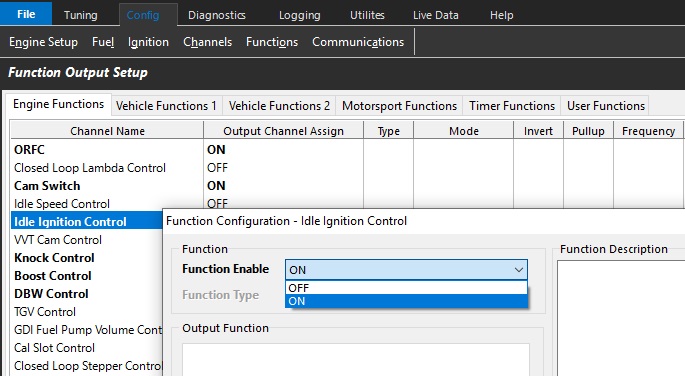
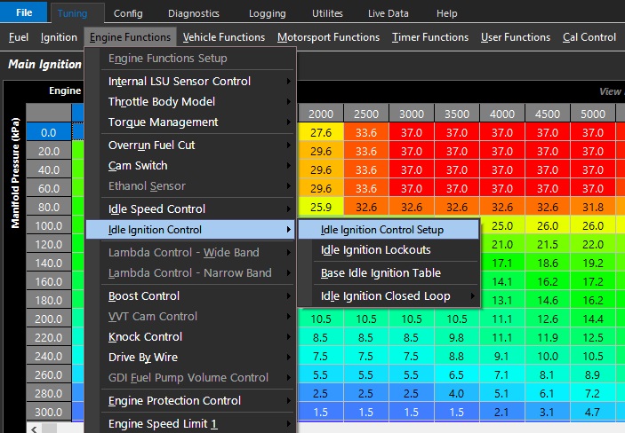
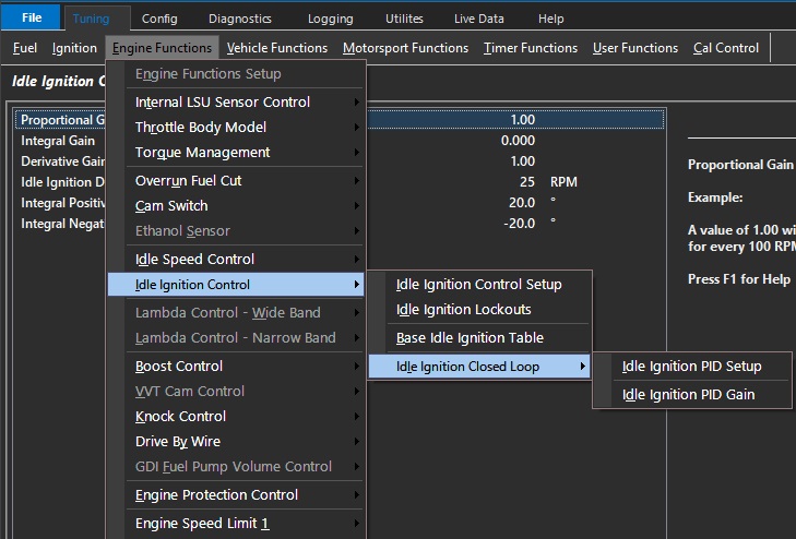
Idle Ignition Control
The Emtron ECU supports idle speed control via ignition timing correction.
Select the control system and appropriate outputs via
Config -> Function Setup -> Engine Functions -> Idle Ignition Control -> ON
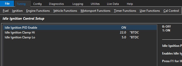
Idle Ignition Control Setup
Idle Ignition PID Enable
Enables Idle Ignition closed loop PID. Without closed loop, the system will still reference the Base Idle Ignition Table (recommended ON).
0: OFF
1: ON
Idle Ignition Clamp Hi/Lo
Sets the minimum and maximum ignition angle the Idle Ignition Control can apply to the Base Timing setting.
Typical: 5 Deg (min), 22 Deg (max)
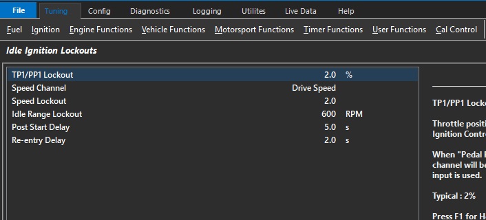
Idle Ignition Lockouts
TP1/PP1 Lockout
Throttle position below which Idle Ignition Control can become active
When “Pedal Position 1” input is active this channel will be used. Otherwise ‘Throttle Position 1"input is used.
Typical : 2%
Speed Channel
Used to define how the “Speed Lockout” is used.
Speed inputs must be defined and properly calibrated under “Input Setup”
Speed Lockout
Locks out Idle Ignition Control when the speed is greater than or equal to this value (KPH).
Typical : 5.0
** Speed Channel must be defined.
Idle Range Lockout
The engine speed must fall below the Idle Target + Idle Range Lockout before Idle Ignition Control becomes active.
Example:
Idle Target = 800 (set from Idle Speed Control menu)
Idle Range Lockout = 400.
Idle Speed Control will become active when the engine speed falls below 1200 RPM.
Typical: 400 RPM
Post Start Delay
Delay after the engine speed has exceeded the crank exit RPM before Idle Ignition Control becomes active.
Typical : 2 sec
Re-entry Delay
Delay once all lockouts are cleared before Idle Ignition Control becomes active.
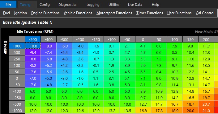
Base Idle Ignition Table
Defines the base ignition angle of the idle ignition control.
This table can be expanded into a 3D look up table using any runtime for axis.
Above example shows the table spanned using Idle Target error & dRPM
Idle Target error references Idle Speed Control Main Idle Target table
** dRPM is the engine Speed rate of change
Idle Ignition Closed Loop Contro
The Emtron ECU adds closed loop correction factors to Idle Speed Ignition functions.
This means it can added closed loop correction factors on top of the base idle ignition angle based on engine speed rate of change VS idle speed target.
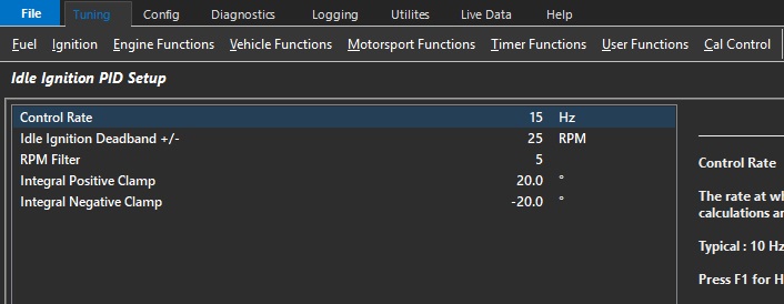
Idle Ignition PID Setup
Control Rate
The frequency or rate at which the PID control algorithm calculations are performed.
Typical : 10 Hz
Idle Ignition Deadband +/-
The output control signal is held constant when the Input Signal (RPM) falls within the deadband range of the Setpoint (RPM Target). This helps reduce steady state error and oscillations.
Typical : 25 RPM
RPM Filter
Filters the RPM signal to allow better PID control
Typical : 5
Integral Positive/Negative Clamp
Allows the user to set the minimum and maximum Integral gain compensation used by the closed loop system.
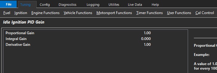
Idle Ignition PID Gain
Proportional Gain
Proportional gain controls how aggressive instantaneous correction must be.
Integral Gain
Integral gain controls how much adaptive correction is needed.
Derivative Gain
Derivative gain controls predictive correction. This function is used to prevent overshooting targets by looking at a number of factors like rate of change, and P and I gain.
Commonly the I gain is not used and this allows the control oscillate over and below the Base Ignition Timing value. This can be important when operating the system in conjunction with an Idle Control valve so the valve position required can remain close to it’s Feed Forward value.
Position Offsets
Offset Position Tables
Allows the user to define a target change to the Initial Position table (Duty Cycle, Step counts, or DBW motor position) during the specified functions:
These tables can be expanded into a 3D look up table using any runtime for the axis.
** These values offset Duty Cycle when using a solenoid, Step counts if using a stepper motor, or Position if using DBW.