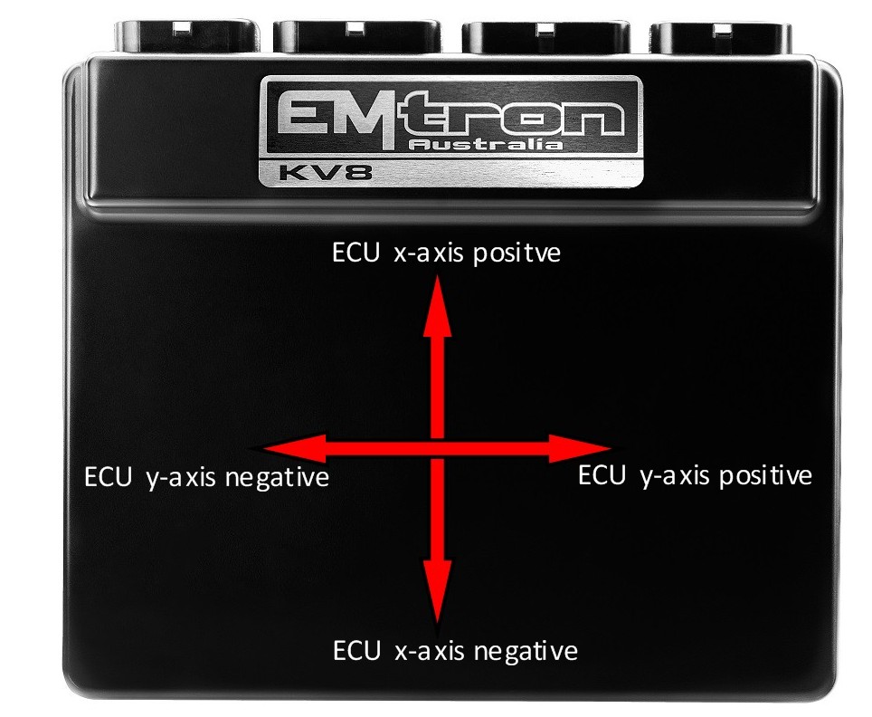
The diagram below shows the orientation of each ECU axis.
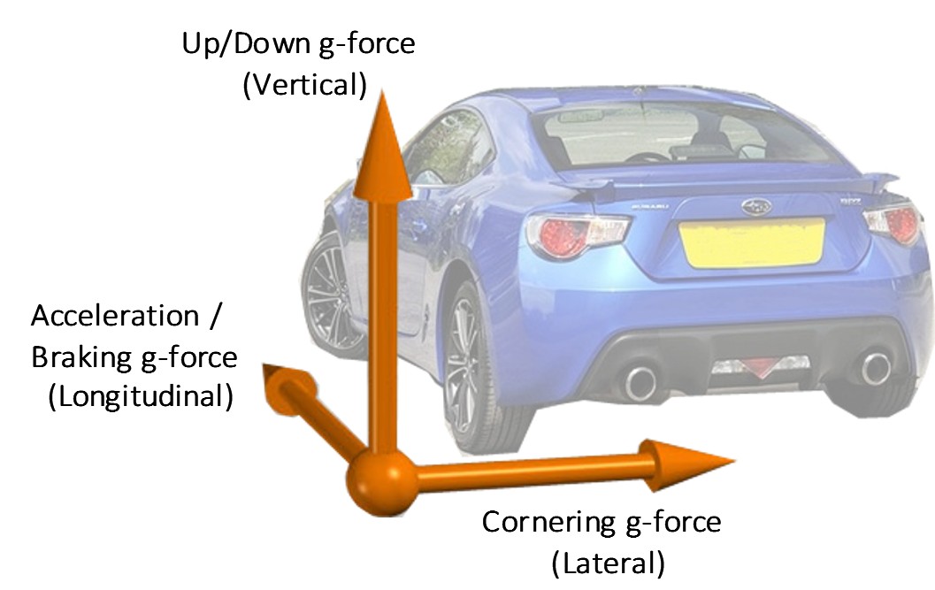
The diagram below shows the orientation of each axis reference from the vehicle.
The ECU allows each vehicle axis to be assigned to an ECU axis (X,Y,Z). For example the Longitudinal Axis can be assigned to the ECUs X or Y or Z axis. This allows the ECU to be mounted at any position/orientation within the car.
These settings are available from the Tuning view > Vehicle Setup > Accelerometer Setup Menu.
Typical Values
Longitudinal positive g-force = Acceleration. Typical values 0.3 to 0.5g
Longitudinal negative g-force = Braking. Typical values: -1.5 to -1.8g
Lateral negative g-force = Turning Left. Typical value for race car on slicks : -1.8g
Lateral positive g-force = Turning Right. Typical value for race car on slicks : 1.8g
Accelerometer Full Range
This sets the maximum g-force that can be measured in any axis. There are 3 Full Range modes adjustable through EMtune.
+-2g
+-4g
+-8g
Normally 2g is enough for most racing applications where there is limited downforce. However, on applications with significant downforce such as under-body trays or large wings then the 4g or 8g option is recommended.
Active Center Differential Pump Control (ACD)
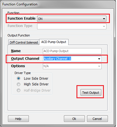
Active Center Differential (ACD) Hydraulic Pump Control
This function reads the pressure from the “Active Center Diff Pressure” input channel and uses this to control the ACD hydraulic pressure. The ECU provides a Pressure Target Table so that different pressures can be targeted under different conditions.
This function can be enabled when the Motorsport Differential Control Function is ON AND an Output Channel has been assigned.
ACD Control Output Status
The following Status information is available from the “ACD Output Status” runtime. This can be viewed from ECU runtime menu, under the Motorsport Tab.
0 = Function is OFF
1 = Output OFF
2 = Output ON
3 = Output OFF- RPM Lockout
4 = Output OFF- User Lockout
5 = Output OFF- Timeout
6 = Output OFF- ACD Pressure Input not selected
7 = Output OFF- ACD Input in Fault
ACD Pump Lockouts
ACD RPM Lockout: The ACD Pump Output will be switched OFF below this Engine Speed. Used normally to switch OFF the Pump during low RPM and cranking.
0 = OFF
Typical Value = 400 RPM
ACD User Lockout: The ACD Pump Output will be switched OFF when the User Channel is ON/Active.
ACD Pump Protection
The following features have been implemented to prevent pump damage:
ACD Timeout Setting. With the Pump ON, if the Target pressure cannot be reached within this timeout value the Pump will be switched OFF. The timer will only be reset when the Lockouts become active or the ECU power is reset.
ACD Pressure Sensor Fault. When the sensor is in fault the Pump will be switched OFF.
ACD Pump Priming.
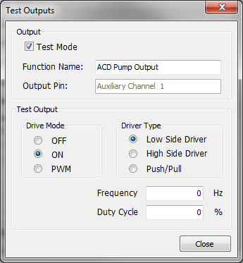
The hydraulic system can be primed using the “Test “Output” function. Simply open this menu, set Test Output to ON and the Pump should start.
CAUTION: Priming the pump should be done with care as the ECUs safety systems are disabled and pump damage may occur.
Boost Control
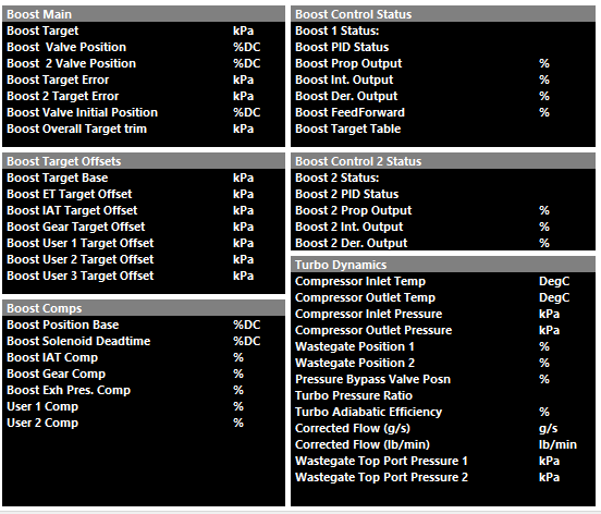
The following calculated runtimes are generated by Emtron that are Boost Control related (to be further discussed more specifically):
Boost Control Function Setup
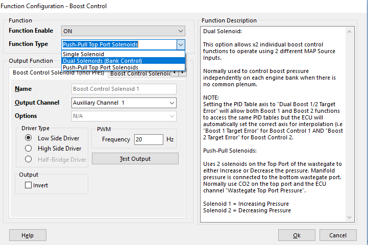
Emtron has three methods of Boost Control
Config > Function Setup > Engine Functions > Boost Control
Single Solenoid
Control of a single solenoid.
Duel Solenoids (Bank Control)
Control of dual solenoids in Bank Configuration.
This option allows 2 individual boost control functions to operate using 2 different MAP Source Inputs.
Normally used to control boost pressure independently on each engine bank when there is no common plenum.
Setting the PID Table axis to “Dual Boost 1/2 Target Error” will allow both Boost 1 and Boost 2 functions to access the same PID tables but the ECU will automatically set the correct axis for interpolation (i.e “Boost 1 Target Error” for Boost Control 1 and “Boost 2 Target Error” for Boost Control 2).
Push-Pull Top Port Solenoids
Uses 2 solenoids on the Top Port of the wastegate to either Increase or Decrease the pressure. Manifold pressure is connected to the bottom wastegate port.
Normally use CO2 on the top port and the ECU channel “Wastegate Top Port Pressure”.
Solenoid 1 = Increasing Pressure
Solenoid 2 = Decreasing Pressure
Some solenoids are sensitive to flywheel diodes on ECU outputs regarding Boost Control and must be matched appropriate.
Standard MAC valve Aux Output – Aux 1-16 – Low Side
AMS/Bullet type valve – Spare Fuel/Ignition channel – Low Side
Valves that need to be ran at higher frequency, or in the case of Push-Pull functionality, where the valves must not float - require non-flyweel controlled outputs (Fuel/Ignition channels) to ensure the control function is appropriate.
See KV Series Hardware Manual section 3.52
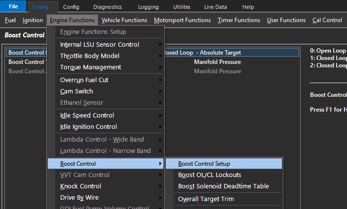
Boost Control Setup
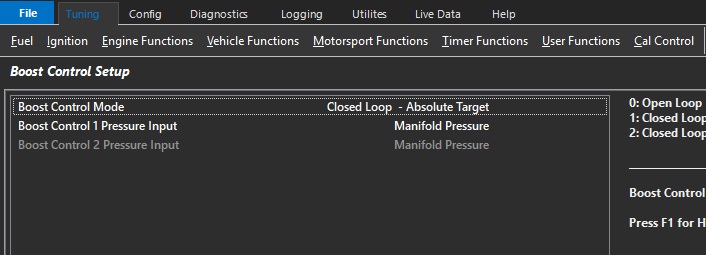
Boost Control Mode
Used to select either Open or Closed Loop.
Open Loop mode is generally used to setup initial settings before using Closed Loop mode.
0: Open Loop
1: Closed Loop – Absolute Target
2: Closed Loop – Gauge Target
Mode 2 works with “0” Manifold Pressure Input only. The ECU generates a channel Manifold Gauge Pressure. Manifold Gauge Pressure is derived from the Barometric Pressure Channel. Barometric Pressure Channel must be configured.
Examples
Absolute Mode
Target = 250kPa. The ECU will Target an Absolute pressure of 250kPa. Boost Pressure inside the engine will increase as Barometric pressure reduces.
Barometric Pressure of 100kPa. Boost pressure inside the engine will be 150kPa.
Barometric Pressure of 80kPa. Boost pressure inside the engine will be 170kPa. (250kPa - 80kPa)
Gauge Mode.
Target = 150kPa. The ECU will Target a boost pressure of 150kPa above Barometric pressure.
Barometric Pressure of 100kPa. ECU Boost Target will be 250kPa, boost pressure inside the engine will be 150kPa.
Barometric Pressure of 80kPa. ECU Boost Target will be 230kPa, boost pressure inside the engine will be 150kPa
Boost Target Tables are used in Closed Loop mode.
Note – Push/Pull Solenoid Mode: Open Loop mode is not available as Closed Loop functionality is required to continuously regulate the target pressure.
Boost Control 1/2 Pressure Input
Allows the Boost Control PID Input/Setpoint to be controlled.
The input for the boost target to be used in closed loop.
0: Manifold Pressure
1: Manifold Pressure - Bank 1
2: Manifold Pressure - Bank 2
3: Manifold Pressure Bank 1/2 Avg
4: Boost Pressure - Bank 1
5: Boost Pressure - Bank 2
6: Boost Pressure Bank 1/2 Avg
7: Wastegate Top Port Pressure 1
8: Wastegate Top Port Pressure 2
9: Boost Pressure
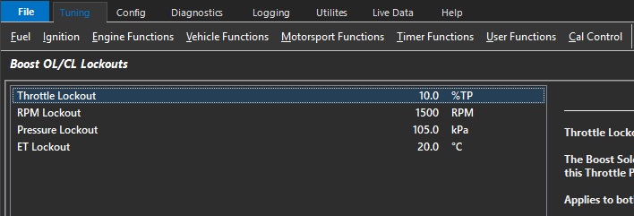
Boost OL/CL Lockouts
\
Throttle Lockout
The Boost Solenoid will switch OFF below this Throttle Position
Applies to both Open and Closed Loop modes
Typical: 10.0% ( 0 = OFF)\
RPM Lockout
The Boost Solenoid will switch OFF below this RPM.
Applies to both Open and Closed Loop modes
Typical : 1200 RPM ( 0 = OFF)
Pressure Lockout
The Boost Solenoid will switch OFF below this pressure
Applies to both Open and Closed Loop modes
Open Loop: ECU uses “Manifold Pressure” runtime
Closed Loop: ECU uses the pressure channel selected in the PID Setup Menu -> Boost 1 PID Input Source
Typical : 110 kPa ( 0 = OFF)
ET Lockout
The Boost Solenoid will switch OFF below this Engine Temperature
Applies to both Open and Closed Loop modes
Typical : 10.0 °C ( -50.0 = OFF)
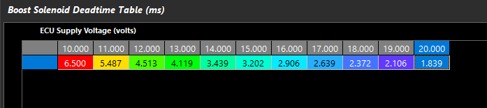
Boost Solenoid Deadtime Table (ms)
This look up table defines the deadtime of the Boost Solenoid.
The deadtime of the solenoid is crucial where control of the boost solenoid duty cycle is especially crucial – IE applications using Push-Pull solenoids or 4-port solenoid control.
Note: Deadtime will automatically add Boost Valve Position %.
A good way to set solenoid deadtime is to do it on a bench and monitor leakage through the valve. Increase deadtime until the brink of leakage, and deadtime is correct.
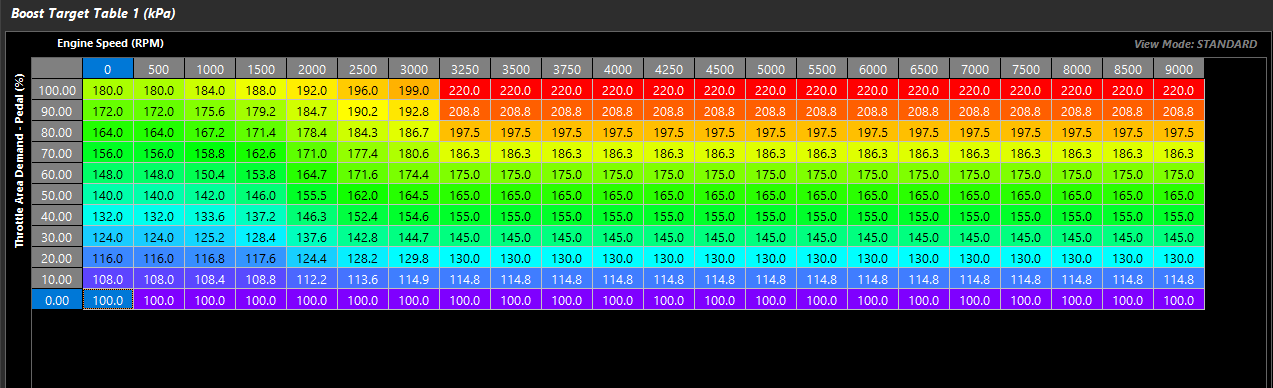
Boost Target Tables
Used by the ECU to determine the base Boost Pressure Target
Boost Control Target can be selected as Absolute or Gauge. NOTE: The ECU will always generate the final Boost Target as Absolute value.
Absolute Mode. This is the Target Boost Pressure independent of Barometric Pressure.
Gauge Mode. This is the Target Boost Pressure above Barometric Pressure
Example.
Absolute Mode. Target = 250kPa. The ECU will Target an Absolute pressure of 250kPa. Boost Pressure inside the engine will increase as Barometric pressure reduces.
Barometric Pressure of 100kPa. Boost pressure inside the engine will be 150kPa.
Barometric Pressure of 80kPa. Boost pressure inside the engine will be 170kPa. (250kPa - 80kPa)
Gauge Mode. Target = 150kPa. The ECU will Target a boost pressure of 150kPa above Barometric pressure.
Barometric Pressure of 100kPa. ECU Boost Target will be 250kPa, boost pressure inside the engine will be 150kPa.
Barometric Pressure of 80kPa. ECU Boost Target will be 230kPa, boost pressure inside the engine will be 150kPa
Boost Target Table 1/2/3
3 tables are available depending on CAL slot control or Boost Table Control
Table are active when closed loop boost control are active
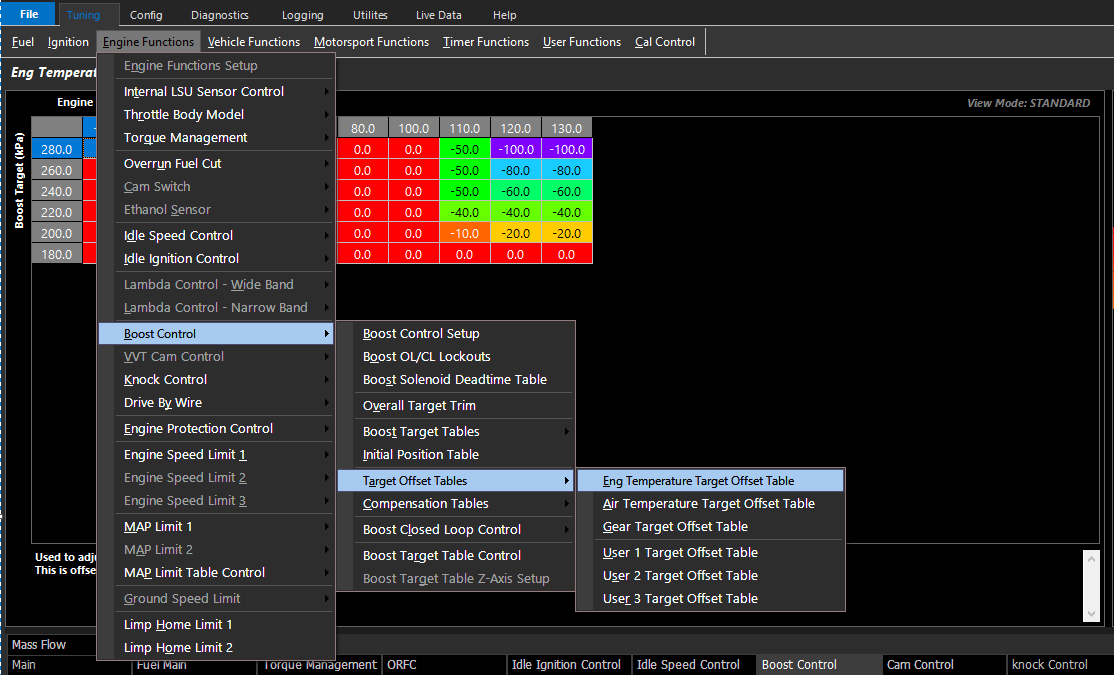
Offset Target Tables
Allows the user to define a target change to the Boost Target during the specified functions:
These tables can be expanded into a 3D look up table using any runtime for the axis.
Target Offsets are specific tables and 3 additional user definable tables.
Boost Target Clamp Table
Clamps the final Boost Target.
0 kPa or 500.0 kPa= OFF.
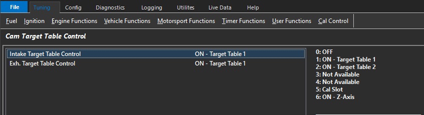
Boost Target Table Control
Selects the active control method of the Boost Target Table
0: Not Available
1: ON - Target Table 1
2: ON - Target Table 2
3: ON - Target Table 3
4: Not Available
5: Cal Slot
6: ON - Z-Axis
Boost Target Table Z-Axis Setup
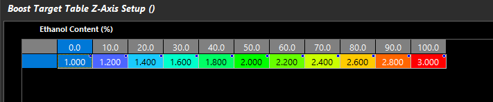
When using Mode 6 in Boost Target Table Control, Boost Target Table Z-Axis Setup becomes available
Blend through the 3 different Boost Target Tables using Emtron available Runtimes.
1.000 = Table 1
2.000 = Table 2
3.000 = Table 3
1.750 = 75% of the way between Table 1 and Table 2.
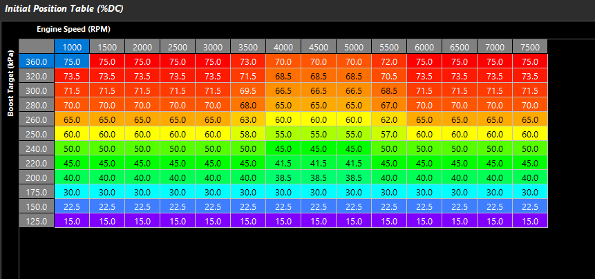
Initial Position Table
Used by the ECU as the main feed forward value to determine the output duty cycle.
This table is used in Open Loop Mode
Initial position is the feed forward for Boost Valve Position %, and the closed loop PID if CL is active.
Boost Valve Deadtime is pre-calculated and added to Initial Position.
Push/Pull Solenoid Control will require no/very little initial position.
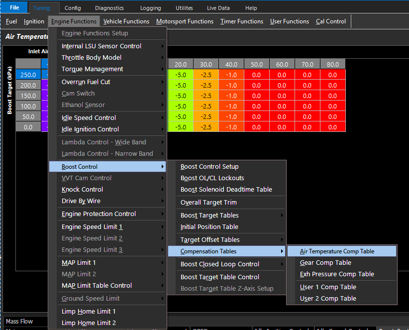
Compensation Tables
Offset change to the Initial Position table (Duty Cycle %) during the specified functions:
These tables can be expanded into a 3D look up table using any runtime for the axis.
Boost Closed Loop Control
For 4 Port Solenoid and Push-Pull Top Port Solenoid Control, it is advised to use much smaller gains to start.
Control Rate
The rate at which the PID control algorithm calculations are performed.
Typical : 25 Hz
Boost Deadband +/-
The output control signal is held constant when the Input Signal (normally MAP) falls within the deadband range of the Setpoint (Boost Target). This helps reduce steady state error and oscillations.
Typical : 2 kPa
Input Filter
Filters the Input signal to help smooth out any pulsations
Note: Input Signal usually MAP.
Typical Value: 5 ( 0 = OFF)
Target Filter
Filters the Target signal to help smooth out any pulsations
Typcial Value: 4 ( 0 = OFF)
Pos/Neg Integral Limit Tables
The minimum or maximum Integral Gain the Boost Control system can apply
Min/Max Duty Tables
The minimum or maximum duty cycle the Boost Control system can apply
Cal Slot Control
Cal Slot Control
This function in an extremely powerful feature which allow the user to customize special calibration slots.
There are 4 calibration slots available.
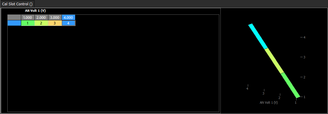
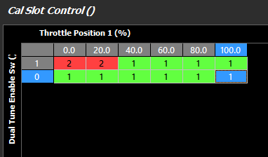
There are 4 Calibration slots which the user may configure. The cal slot is controlled through the 3D user table “Cal Slot Control”. Below is a simple example of how the cal slots could be switched. In this case AN Volt1 has been configured on the X axis. If AN Volt 1 is between 0.0V and 1.49V then Cal Slot 1 will be selected. If AN Volt 1 is between 1.50V and 2.49V then Cal Slot 2 will be selected and so on.
The corresponding table must be configured to be Cal Slot controlled. In this case the Fuel Tables will be configured to be controlled by the Cal Slot.
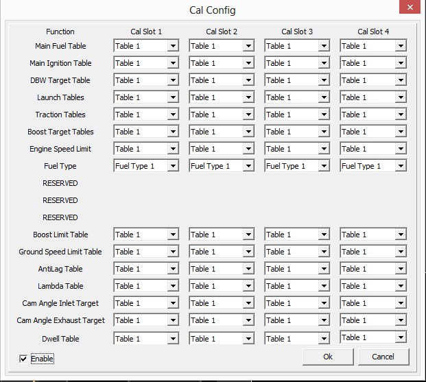
Below is the Cal Config table. This is where the tables are linked to the Cal Slot. In the below example Table 1 is used no matter what Cal Slot is selected.
The slot positon is defined by the setup of the Cal Slot Control table.
The Cal Slot Control table can be expanded into a 3D axis and any runtimes can be used to select each slot. This can be setup to use simple digital switch inputs, rotary position sensors, and/or any other runtime the user needs. This includes live runtime data that can aid in “automatic” cal switching.
Examples table axis:
Simple digital input
Rotary position switch
Analog voltage input
Temperature runtimes
Dual tune enable runtimes
Engine load runtimes
The above example looks at Dual Tune Enable switch as a condition for the Y axis, but the slot position is still dependant on Throttle Position on the X axis. If the engine is throttled past 20%, the ECU will automatically switch back to Cal Slot 1.
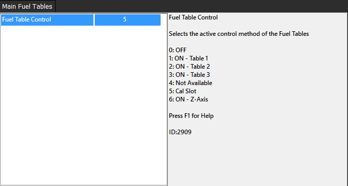
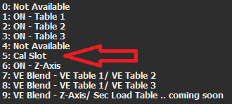
In order for the Cal Slot configuration to work properly, under all Table Controls (see Table Control) being used, “Cal Slot” must be selected
All Emtron ECU’s can support variable camshaft position control (VVT – Variable Valve Timing). Up to 4 Cam Control channels can be configured depending on the ECU model (two intake, two exhaust).
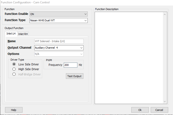
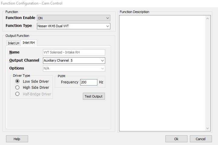
Select the control system and appropriate outputs:
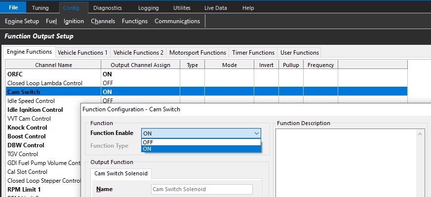
Config View -> Function Setup -> Engine Functions -> Cam Control
OFF = Function is switched off and the selected output channels are deallocated.
ON = Function is switched on.
Function Type
Choose the supported VVT system from the list.
Output Channel Selection
All Emtron outputs can be configured for Cam Control, however standard Aux Channels should be prioritized for this. Most of Emtron Aux Channels are flexible in regards to output polarity as well (dependant on VVT system being used. All Cam Control systems used closed loop position control - see Cam Switch for open loop control)
Sl4/SL8 - Aux 1 – 8 Low side, Aux 5 – 8 High side, Aux 9 – 10 Half bridge
KVx Rev 1 - Aux 1 – 8 Low/High side, Aux 9 – 12 Half bridge, Aux 13 – 16 Low side
KV8 Rev 2 - Aux 1 – 8, 13 - 16 Low/High side, Aux 9 – 12 Half bridge
KV12 Rev 2 - Aux 1 – 8 Low/High side, Aux 9 – 16 Half bridge
KV16 Rev 2 - Aux 1 – 8 Low/High side, Aux 9 – 16 Half bridge
Spare fuel and ignition channels are Low side. Prioritize VVT channels to Aux channels.
Channel selection is as follows:
Inlet LH - Bank 1 intake camshaft
Exhaust LH - Bank 1 exhaust camshaft
Inlet RH - Bank 2 intake camshaft
Exhaust RH - Bank 2 exhaust camshaft
Driver Type
Select either Low side, or High side depending on the VVT system being used.
See engine wiring schematic. VVT solenoids are normally supplied with constant 12V+ or ground (use opposite control polarity).
BMW VANOS
BMW VANOS Support
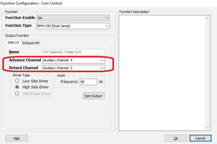
Early BMW Motorsport VANOS systems were unique. It uses an auxiliary oil pump that boosts operating oil pressure to a constantly regulated 100bar of pressure. The high pressure is used to hydraulically lock the cam position to target during all operating conditions. The design of the system requires two channels per camshaft as there is no default position (ie – Intake retarded position, exhaust advanced position). This means there are separate channels for each camshaft for retard and advance. If the control system is at target, the cams remained hydraulically locked by switching the control system off. Because of the unique mechanical nature of the system, ECU control must be very specific. Emtron has developed a special strategy that mimics the OE function, but allows complete flexibility to enable even more precise control.
BMW Engines that use high pressure BMW Motorsport VANOS
BMW S50B30 - Single VANOS intake cam
BMW S50B32 - Double VANOS intake and exhaust cam
BMW S54 - Double VANOS intake and exhaust cam
BMW S62 - Double VANOS intake and exhaust cam (two banks)
USA versions BMW S50B30 (and BMW S52B32) do NOT use BMW Motorsport VANOS.
Later Motorsport models updated VANOS to more conventional control. BMW S65 and BMW S85 use only one output per camshaft like conventional systems.
When selecting these function types, there will be additional options available for choosing the specific channels for retard or advance channels.
BMW Motorsport VANOS is driven high side. If the installer chooses to drive low side, the solenoids MUST be modified as the flyback diodes will now allow them to be driven low. Diodes must be reversed or removed.
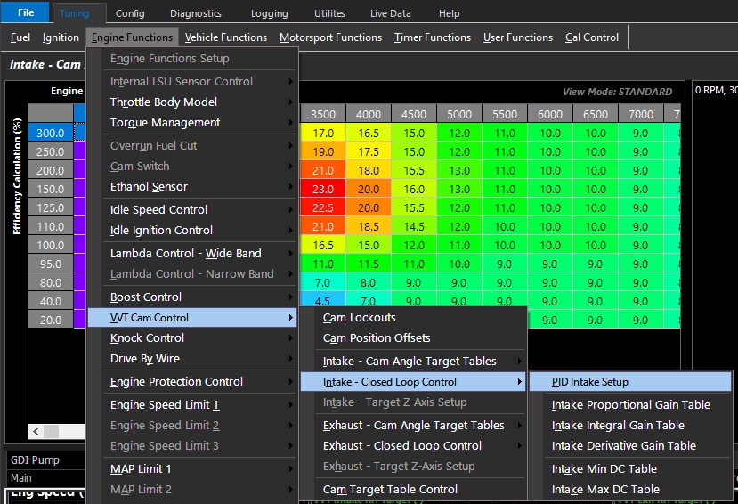
Cam Control - PID
PID Setup
Applicable to both intake & exhaust PID setup
The positioning control of the Camshaft(s) is governed by the Emtron PID closed loop function.
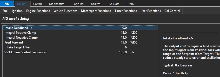
Intake Deadband +/-
The output control signal is held constant when the Input Signal (Cam Position) falls within the deadband range of the Target.
This helps reduce steady state error and oscillations.
**BMW Motorsport VANOS systems switches off the control signal automatically when in deadband to hydraulically lock the cam position.
Typical : 0.5 degrees
Integral Positive Clamp
Allows the user to set the the maximum Integral gain compensation used by the closed loop system.
Integral Negative Clamp
Allows the user to set the minimum Integral gain compensation used by the closed loop system
Feed Forward
Having a correct feed forward duty cycle value allows for more precise control.
This feed forward value is added to the control signal before the PID is applied.
Tuning Tip:
This is the expected duty cycle of the solenoid to hold the camshaft in a given position.
It can be quickly determined by commanding the camshaft to a position & witnessing the required duty to do so.
Commanding an alternative angle will deliver a similar result, the average of these is your feed forward value.
Intake Target Filter
Filters the Target signal to help smooth out any pulsations.
Typical Value: 5 ( 0 = OFF)
VVTiE Base Control Frequency
Toyota 2URFSE/2URGSE VVTiE Base frequency setting at 1000rpm
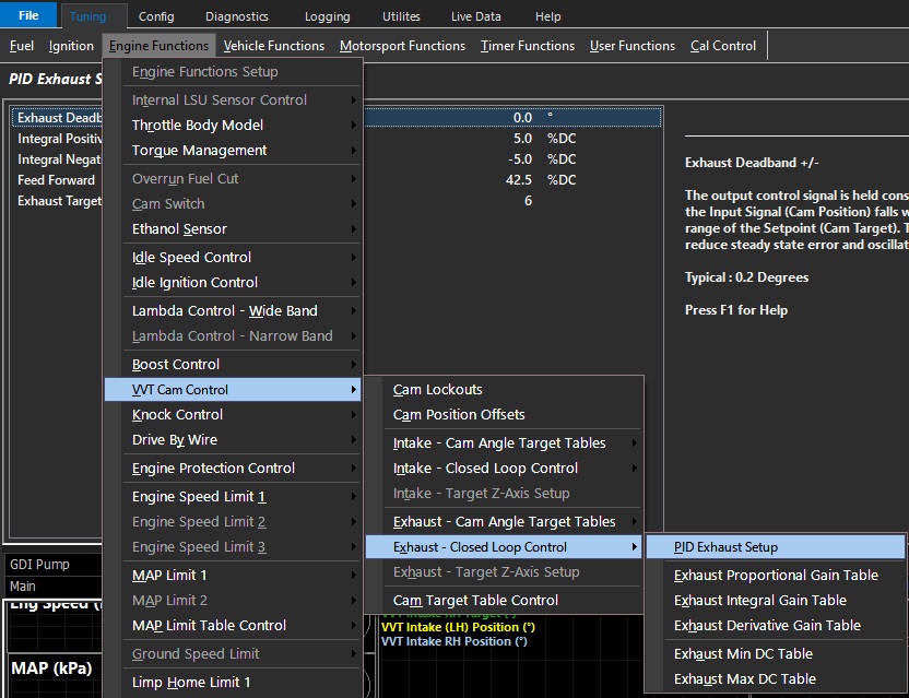
For PID Exhaust setup
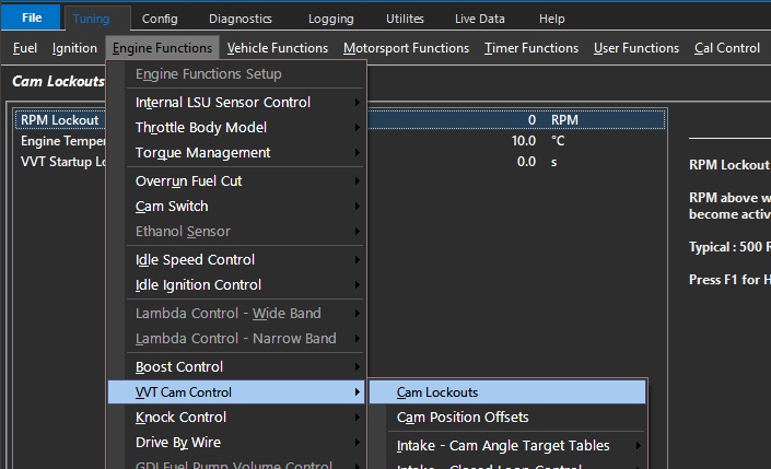
Cam Lockouts
CAM Lockouts
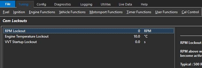
RPM Lockout
RPM Lockout
Engine speed above which Cam Control is set to become active
Typical : 500 RPM
Engine Temp Lockout
Engine Temp above which Cam Control is set to become active.
Typical : 60 degC
VVT Startup Lockout
Delay timer from Crank RPM Exit before VVT Cam Control is permitted to become active.
This setting helps prevent the Cam Control Solenoid “Rattling” at startup due to low oil pressure.
Typical : 500 RPM
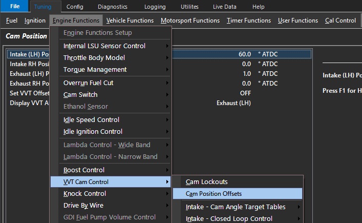
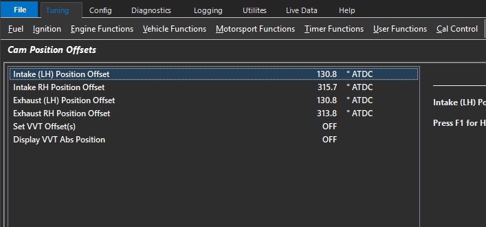
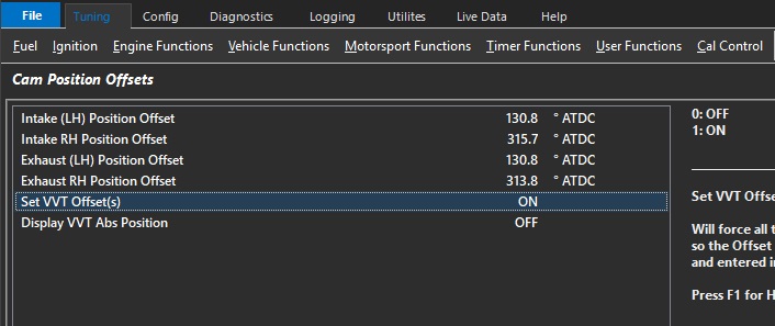
Cam Position Offsets
Like Crank Position Offset, the ECU must know the offset position of each Camshaft used for Cam Control as well.
The offset allows the target look up table to either add or subtract desired position based on this entry.
To program the Position Offset, the ECU must put the engine into a special mode to return the camshafts to default positions (intake retarded, exhaust advanced).
Generally, this forces the ECU to stop attempting to regulate the camshafts (VVT solenoids OFF).
There are 2 methods to achieve the same goal.
Method 1
Start engine (warm engine)
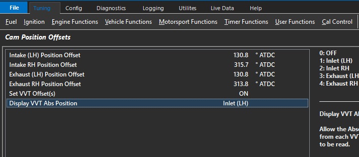
Set VVT Offset(s) = 1 (ON)
Display VVT Abs Position = choose camshaft to display
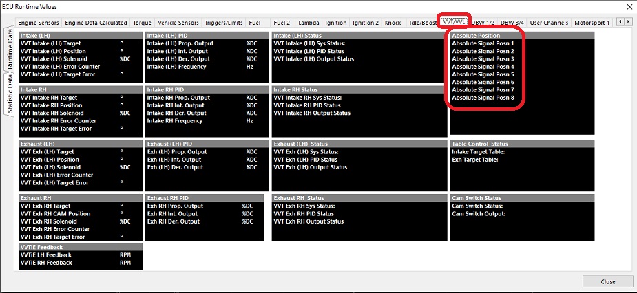
Under Runtimes (F3, VVT/VVL)
Use absolute position runtimes to populate the offset.
Each position represents either a rising or falling edge per cycle (dependent on edge selection under inputs). Choose the lowest number.
Method 2
Whilst on the Cam Position Offset page
Start engine (warm engine)
Set VVT Offset(s) = 1 (ON)
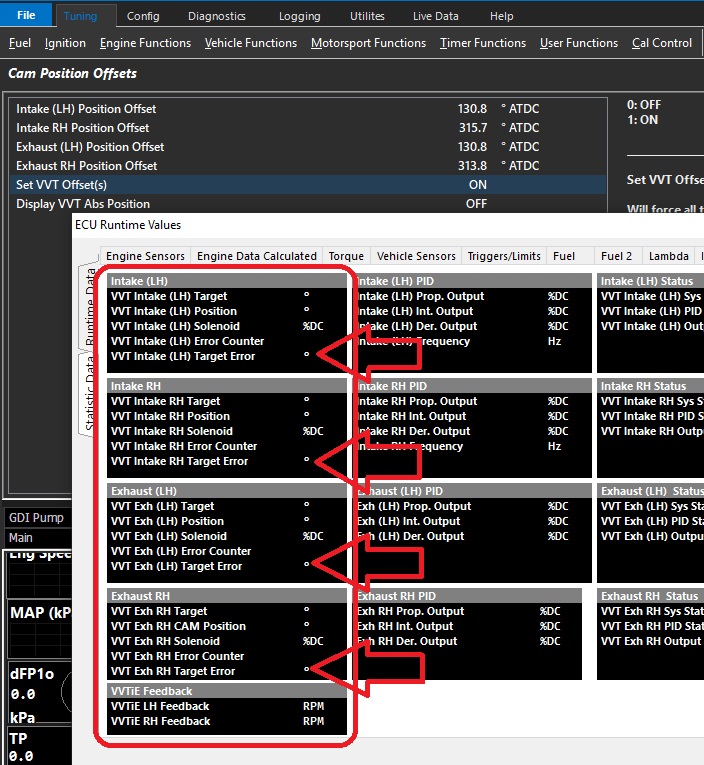
Open ECU Runtimes (F3) go to VVT/VVL
Use the VVT target Error to validate the position offset number.
This can be do by simply increasing or decreasing the value until as close to zero error is achieved.
Once completed for each cam, set VVT Offset(s) to = 0 (Off)
BMW VANOS Support
Because BMW Motorsport VANOS systems to not return to default positions when the VVT solenoids are OFF, Emtron has a specialized function that will automatically apply a constant duty to the intake retard channels and exhaust advance channels when the Set VVT Offset(s) mode = 1. This allows the user to program the Position Offsets for each camshaft as normal.
Cam Switch
The Emtron ECU Cam Switch function is a comprehensive function to control simple cam switch solenoids
(VTEC, Lift solenoids, advance/retard solenoids).
Instead of just having standard switch criteria like a simple RPM or load threshold, the Emtron Cam Switch function has a series of setup functions, plus a 3D table to control its activation.
The 3D table should not be mistaken for a PWM duty table – This is not a closed loop control system.
For PWM duty control, use the VVTCam Control function.
Output Setup
Output Channel Selection
Select open outputs that are appropriate for the type of Cam Switch system you are using
Driver Type
Set Low or High side function
Frequency
There should be no frequency/PWM function enabled for this function. It is a “switch” function only.
Function Setup
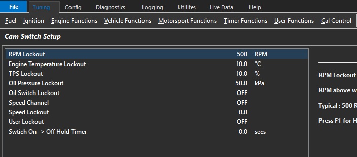
RPM Lockout
RPM above when the Cam Switch can become active. Typically 500rpm.,
Engine Temp Lockout
Temperature above when the Cam Switch can become active. Typically 20 DegC
TP Lockout
Throttle above when the Cam Switch can become active. Typically 10.0%
Oil Pressure Lockout
Oil Pressure above when the Cam Switch can become active. Only applies if Oil Pressure Input Channel has been configured.
Oil Switch Lockout
Used to ensure there is oil pressure when the Cam Switch can become active. Only applies if Oil Pressure Switch Input Channel has been configured.
Speed Channel
Select Speed Channel to be used for Speed Lockout (below)
Speed Lockout
Speed above when the Cam Switch can become active. Typically 5kph.
User Lockout
Allows the Cam Switch function to be locked out by a user function. When the User Function is ON, the lockout is active.
Switch ON -> OFF Hold Timer
When the Output has been commanded to switch OFF, this setting will keep the Output ON for the time entered. Useful for example by allowing the Output to remain ON during gearshift.
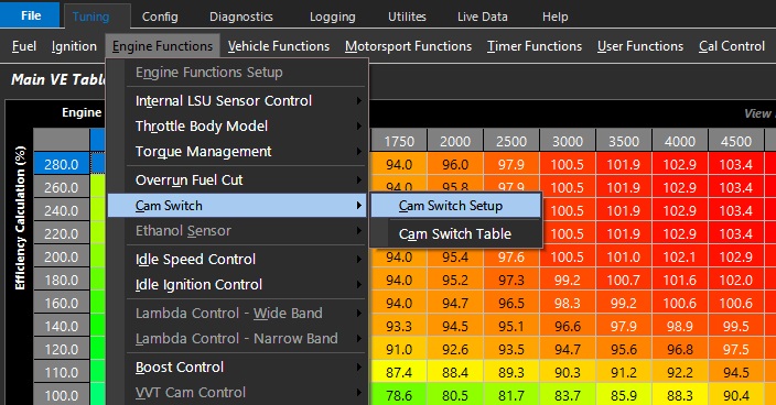
Cam Switch Table
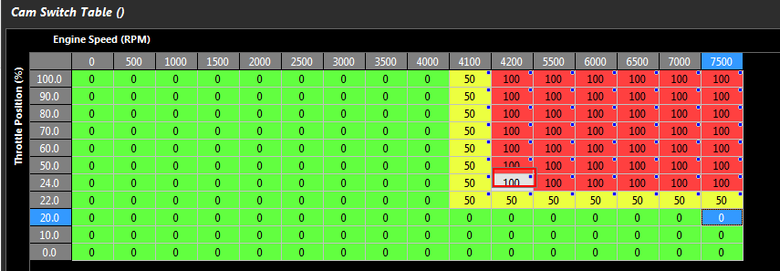
This look-up table commands the ECU to switch the Cam Switch Output OFF, ON, or remain unchanged.
Value 0 = Cam Switch OFF
Value 100 = Cam Switch ON
Any number in between 1-99 is hysteresis mode which causes the output to remain unchanged. Typical value used is 50. This prevents the Cam Switch function output toggling ON/OFF when the mapped point is close to the edge of activation.
The above picture illustrates an example of how to implement hysteresis in a CAM Switch Table.
RPM Axis. Between 4001 and 4199 there is no output change defined by a Table value of 50. With increasing RPM at 4200 the output will Switch ON defined by a Table value of 100. With Decreasing RPM at 4000 the Output will Switch OFF defined by a Table value of 0. The result is a Hysteresis of 200 RPM
Throttle Position. Between 20.1% and 23.9% there is no output change defined by a Table value of 50. With increasing Throttle at 24.0% the output will Switch ON defined by a Table value of 100. With decreasing Throttle at 20.0% the Output will Switch OFF defined by a Table value of 0. The result is a Hysteresis of 4% Throttle.
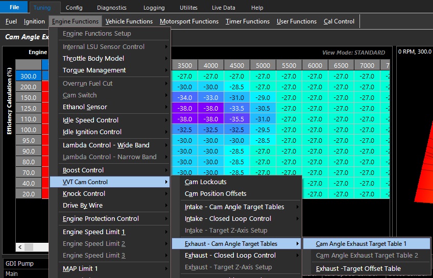
Exhaust Cam Angle Target Tables
Exhaust Cam Angle Target Tables
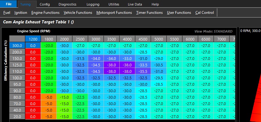
This is the Exhaust camshaft position command tables where the required camshaft position in degrees is set
Table units start from 0.
Negative numbers represent targeting retarded position of the camshaft.
**Typically numbers close to 0 represent the least amount of overlap which helps with idling.
Exhaust Cam Angle Target Table 2 can be accessed/activated via Cam Target Table Control
There are a variety of methods of integration available.
WARNING
Incorrect setting of the Exhaust Cam Angle Target Table can result in engine damage.
In modified engines, the piston to valve clearance of the engine should be measured.
The maximum safe advance angle should be known prior to setting VVT travel range.
If the valve clearance is compromised within the available travel range a mechanical limit should be employed to prevent contact.
DO NOT rely on closed loop Cam Control to prevent piston to valve contact when there is a mechanical ability to cause contact.
BMW Motorsport VANOS should not be targeted to the fully retarded or advanced position at any point.
This is because the system is designed to hydraulically lock the position once at the target (no solenoid regulation).
If for whatever reason the offset position is not exact (some variance with temp, engine speed, etc), the system could potentially over-regulate the solenoids.
Targeting a few degrees before each end stop is typical and mimics the OE function.
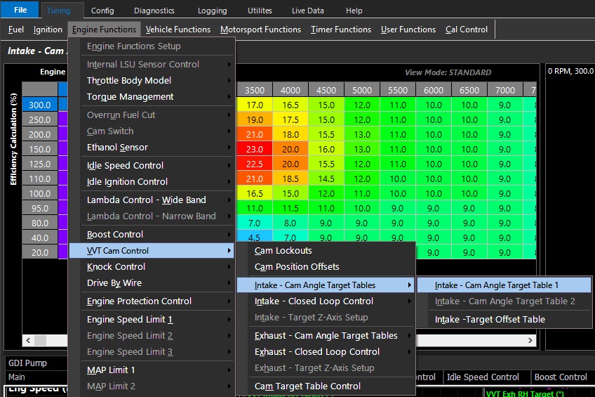
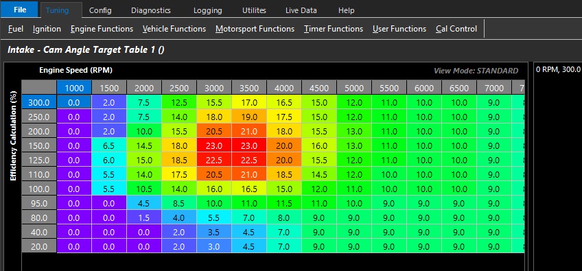
Intake Cam Angle Target Tables
Intake Cam Angle Target Tables
This is the Intake camshaft position command tables where the required camshaft position in degrees is set
Table units start from 0.
Positive numbers represent targeting advanced position of the camshaft.
**Typically numbers close to 0 represent the least amount of overlap which helps with idling.
Intake Cam Angle Target Table 2 can be accessed/activated via Cam Target Table Control
There are a variety of methods of integration available.
WARNING
Incorrect setting of the Intake Cam Angle Target Table can result in engine damage.
In modified engines, the piston to valve clearance of the engine should be measured.
The maximum safe advance angle should be known prior to setting VVT travel range.
If the valve clearance is compromised within the available travel range a mechanical limit should be employed to prevent contact.
DO NOT rely on closed loop Cam Control to prevent piston to valve contact when there is a mechanical ability to cause contact.
BMW Motorsport VANOS should not be targeted to the fully retarded or advanced position at any point.
This is because the system is designed to hydraulically lock the position once at the target (no solenoid regulation).
If for whatever reason the offset position is not exact (some variance with temp, engine speed, etc), the system could potentially over-regulate the solenoids.
Targeting a few degrees before each end stop is typical and mimics the OE function.
Intake/Exhaust Target Offset Tables
Intake/Exhaust Target Offset Tables
These are user defined tables are used to offset the Cam Target.
The tables operate in Absolute values (degrees).
Cruise Control
Cruise Control Application Build
1.0 Introduction
The Cruise Control Application Build is available for all Emtron ECUs. This build allows unique application-specific firmware to be installed into the ECU. The strategy involves the ECU managing engine torque (Nm) by calculating the correct throttle area for the target vehicle speed. The speed error is then corrected using a PID controller.
It is important that the throttle body model is calibrated and the engine model is correctly configured. The air flow model using the throttle mass flow calculation (TMF) requires a pressure reference pre and post throttle. In naturally aspirated applications the use of barometric pressure for the pre-throttle channel will be enough to achieve reasonable results; however, it is recommended to install a pressure sensor pre-throttle. Turbocharged applications must run a pre-throttle pressure sensor. Any of the three boost pressure input channels may be used for the pre-throttle pressure.
For further information on Throttle Mass Flow (TMF), refer to the Help Topic “Throttle Mass Flow Setup” in the Emtune software for a detailed explanation on how to configure and tune this system properly. DO NOT attempt to use the Cruise Control function until TMF calibration is complete.
WarningDISCLAIMER Cruise Control is designed to assist the driver and is not a substitute for safe and attentive driving practices. Any failure to follow the directions provided in the Cruise Control Application Build is at the sole risk of the user. Not all vehicle configurations allow the use of Cruise Control due to hardware limitations. Emtron Australia will not be liable for any physical or financial injury, loss or damage arising from the improper use or improper setup of this function.
2.0 Build Setup
The Cruise Control Application Build needs to be enabled by an authorised Emtron dealer before it may be installed into the ECU. Each build is locked to an ECU serial number, then available for installation from the Emtron online server.
2.1 Installation procedure
Internet access is required for the build installation, allowing Emtune to access the Emtron online server.
Connect Emtune to the ECU.
Firmware Version 2.17.0 or later should be used.
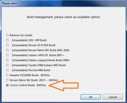
Select the File → Build Management menu. A window will open and display all build options.
Select the Cruise Control option which should be listed as INSTALL. Press OK.
The installation process will take 5-10 seconds. A message box will confirm a successful installation.
To further verify the installation and view the status of all available builds, open the Runtime menu (F3) and select the “ECU Internal” tab.
File → Build Management — install the Cruise Control build.
2.2 Uninstall procedure
If the build has been previously installed it can be uninstalled at any time. With internet access and Emtune connected, select File → Build Management, select the Cruise Control option (listed as UNINSTALL), and press OK. The uninstall process takes 5-10 seconds.
3.0 Configuration
For the function to operate correctly the following minimum requirements MUST be adhered to.
3.1 Input Switches
Brake Switch
Clutch Switch (Manual Transmission with mechanical clutch)
The Cruise Control Status runtime will update to indicate which condition is locking out the function.
3.5 Function Enable
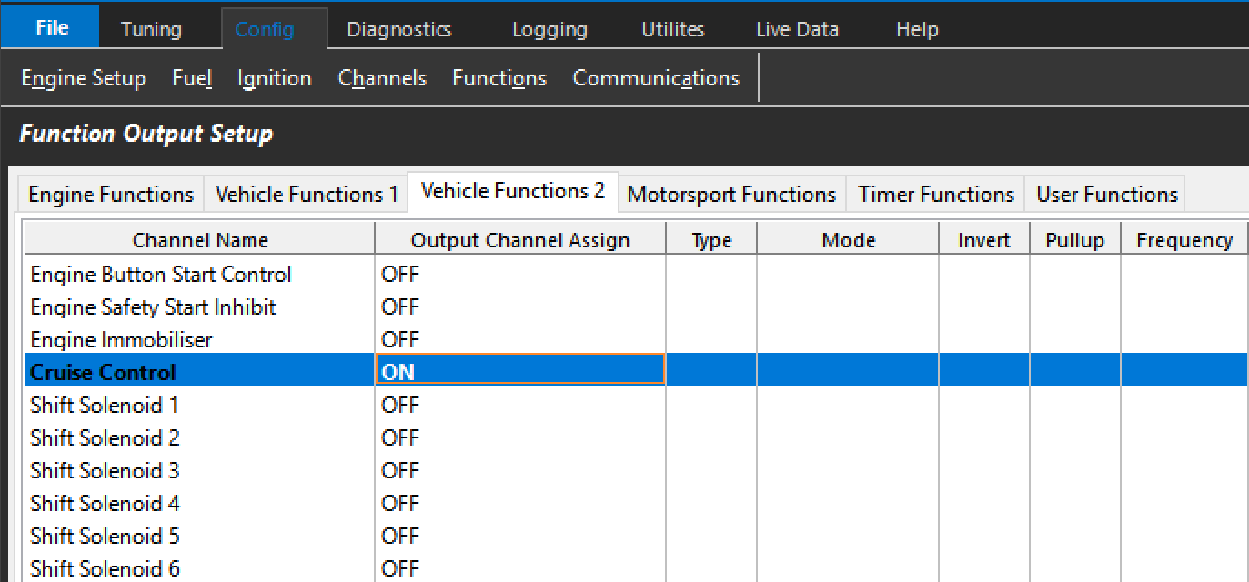
Once the Cruise Control Build is enabled, the function needs to be enabled via Config → Functions → Function Output Setup → Vehicle Functions 2 → Cruise Control.
4.0 Tuning System
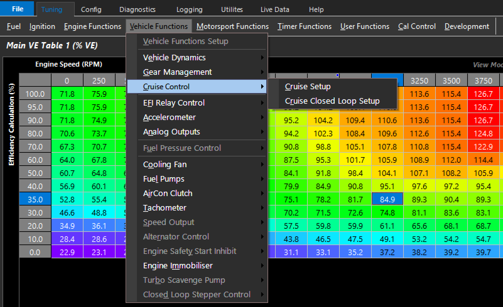
Calibration of the Cruise Control system is done in the Emtune Tuning View tab: Tuning → Vehicle Function → Cruise Control → Cruise Setup.
4.1 Cruise Setup
Cruise Max Target Speed — The maximum target speed that can be set. The ECU clamps to this value.
Cruise Resume Speed Incr Ramp Time — The time the ECU will gradually increase the speed target back to the previously “Set” speed after a lockout has been invoked, to achieve a smooth acceleration rate back to the target speed.
Cruise Resume Speed Decr Ramp Time — The time the ECU will gradually decrease the speed target back to the previously “Set” speed after a lockout state has been cleared, to achieve a smooth transition back to the target speed.
4.2 Cruise Closed Loop Setup
The system relies on a combination of feedforward TMF torque-based latching coupled with a PID system to control the speed.
Cruise Control Speed Channel — Any speed channel in the ECU may be used as the input channel. This is used by the speed target.
Cruise Proportional Gain — The gain due to the instantaneous error in speed. Typical value 1.00.
Cruise Integral Gain — The gain due to the error with respect to time. Typical value 0.010.
Cruise Derivative Gain — The gain due to the rate of change of the error. Typical value 12.00.
Cruise Deadband +/- — The speed range which will hold the output. Typical value 0.2 km/h.
Cruise Maximum Torque Clamp — The maximum clamp the system can use to attain the target speed. Set to allow the system enough torque to always achieve the target. Typical value 200-300 Nm.
Cruise Minimum Torque Clamp — The minimum clamp the system can use to attain the target speed. Usually set to ensure maximum deceleration. Typical value -100 Nm.
The system employs an error counter which is triggered when the Cruise Minimum/Maximum Torque Clamps have been hit. The larger the target error when the torque clamps are latched, the faster the error counter increments. The system shuts down once the counter reaches the pre-determined (non-user-adjustable) value.
Cruise Control closed loop (PID) setup.
4.3 Runtimes
Accessed via the ECU Runtime Menu (F3): Runtime Data → Vehicle Functions → Cruise Control.
Figure 3.0 — Runtime menu, Cruise Control runtimes.
Cruise Control Status — the current system status:
Disabled — System is OFF
ON — System is currently active
… Waiting SET/RESUME Sw — System is armed but in a lockout state awaiting user input to re-engage
Starting-SET Pressed — Set has been pressed and the system will become active. The current speed is loaded as the “Speed Target”
Restarting-RESUME Pressed — The system will resume and the last loaded Speed Target will be re-engaged
ON – Paused Pedal — The system is active but the driver is inputting a higher throttle area demand than is being requested. Normal operation resumes after the driver input is removed. As this state is controlled by the pedal area demanded, it is important that the “Pedal to Throttle Area Translation Table” has a 0.0 setting in the “Pedal Position Demand” 0% axis.
Other runtimes: Cruise – Torque Target Base (TMF) (the TMF calculated torque value loaded as the base torque reference, converted into a throttle area demand); Cruise – Torque Target Final (TMF) (the PID-adjusted torque output using the base as feedforward); Cruise – Speed Target; Cruise – Speed Input (the actual reported speed); and the switch states Cruise RESUME Sw / SET Sw / CANCEL Sw / ON/OFF Sw (monitor these to confirm correct button assignment).
Appendix A – Bit CAN Message Information (“Cruise Control Status”)
Bit
Status
Bit
Status
0
Disabled
25
OFF-Brake Switch
1
ON
26
OFF-Neutral
2
… Waiting SET/RESUME Sw
27
OFF-Clutch Switch
3
Starting-SET Pressed
29
X-TMF Disabled
4
Restarting-RESUME Pressed
30
X-TMF1 Sensor Before Fault
5
ON - Paused Pedal
31
X-TMF1 Sensor After Fault
20
OFF-Cruise Enable Sw
32
X-TMF2 Sensor Before Fault
21
OFF-Cruise Cancel Sw
33
X-TMF2 Sensor After Fault
22
OFF-Engine Speed Zero
34
X-Cruise Enable Sw Config
23
OFF-Ref Speed Zero
35
X-Cruise SET Sw Config
24
OFF-Limiting Active
36
X-Cruise RESUME Sw Config
37
X-Cruise CANCEL Sw Config
38
X-Speed Source Config
39
X-Brake Input Config
40
X-Firmware Lockout
Differential Control
Overview
The ECU can electronically control a Differential by modulating a solenoid at a fixed frequency and varying duty cycle.
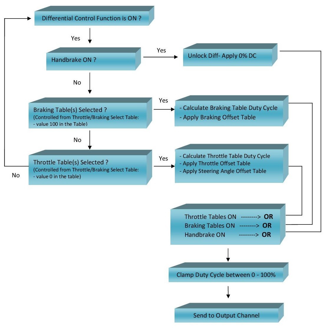
The Differential Control and corresponding output duty cycle is determined by 3 different operating modes. A flow chart in the next section provides a visual overview of how the system works.
1) Handbrake. When this input is configured and the handbrake is ON the ECU applies 0%DC at its control output to unlock the diff. This overrides all other controls.
2) Throttle/Braking Select Table. This controls the selection of either the Throttle tables or Braking tables.
3) Braking Table. Used when the vehicle is under braking conditions.
4) Throttle Table. Used when the vehicle is under normal driving conditions.
Differential Control Status
The following Status information is available from the “Differential Output Status” runtime. This can be viewed from ECU runtime menu, under the Motorsport Tab.
0 = Function is OFF
1 = OFF - Output Channel not selected
2 = ON - Handbrake mode active
3 = ON - Throttle Tables active
4 = ON - Braking Tables active
Throttle/Braking Select Tables
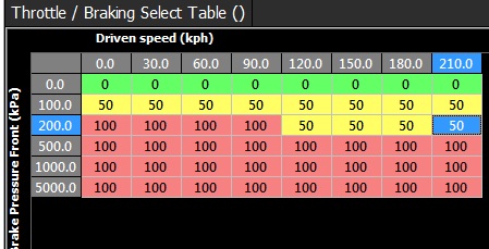
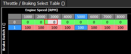
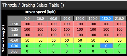
A 3D Table is used to select which Table controls the Duty Cycle to the Differential. This is either the Throttle Table(s) or Braking Table(s).
Table value 0 = Throttle Table(s)
Table value 100 = Braking Table(s)
Any other value = no change (hysteresis) . Normally use a value of 50 for this
There is nointerpolation on this table.
This allows for a number of different strategies to control the switching between these two tables.
Examples:
Using Brake Pressure and Speed
Using Brake Switch and Speed. 0 = Brake switch OFF, 1 = Brake Switch ON.
Using Longitudinal g-force from the ECUs internal accelerometer and Speed. A negative g-force is braking.
Braking Tables
When this mode is active 2 tables are used to generate the final Duty Cycle:
Main Braking Table
Braking Offset Table
Example:
Braking Table = 100%
Braking Offset Table = -10%
Final Duty Cycle = 100% -10% = 90 %DC
Throttle Tables
When this mode is active 3 tables are used to generate the final Duty Cycle:
MainThrottle Table
Throttle Offset Table
Steering Angle Offset Table
Example:
Throttle Table = 23%
Throttle Offset Table = -13%
Steering Angle Offset Table. = +8%
Final Duty Cycle = 23% -13% + 8 % = 18 %DC
Control Flow Chart
Drive By Wire
All KV Series and SL Series ECU’s support from 1 up to 4 independently controlled Drive by Wire (DBW) Systems.
The DBW availability is ECU based and summarized below:
Shadow 8 - 1 motor
SL4 and SL8 – 1 motor
KV8 – 2 motors
KV12, KV16 (Rev2) – 4 motors
Select the control system and appropriate outputs from:
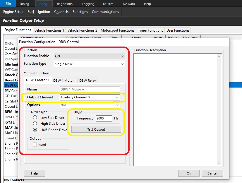
Config View -> Function Setup -> Engine Functions -> DBW Control
OFF = Function is switched off and the selected output channels are deallocated.
ON = Function is switched on
Function Type
4x DBW channels: (3 and 4 channels are only available on KV12/KV16 Serial Number > 1350)
Single DBW - Using 2 Half-Bridge Drivers
Dual DBW - Using 4 Half-Bridge Drivers
3 Channel - Using 6 Half-Bridge Drivers
4 Channel - Using 8 Half-Bridge Drivers
** See graphic above – Yellow
Output Channel Selection
There are dedicated paired outputs for each DBW channel.
DBW x Motor +ve (Positive) = Auxiliary 9 - 5A Continuous 8A Limit
DBW x Motor -ve (Negative) = Auxiliary 10 - 5A Continuous 8A Limit
OR
DBW x Motor +ve (Positive) = Auxiliary 11 - 5A Continuous 8A Limit
DBW x Motor -ve (Negative) = Auxiliary 12 - 5A Continuous 8A Limit
OR KV12 and KV16 Rev2
DBW x Motor +ve (Positive) = Auxiliary 13 - 10A Continuous 20A Limit
DBW x Motor -ve (Negative) = Auxiliary 14 - 10A Continuous 20A Limit
.
OR KV12 and KV16 Rev2
DBW x Motor + (Positive) = Auxiliary 15 - 10A Continuous 20A Limit
DBW x Motor - (Negative) = Auxiliary 16 - 10A Continuous 20A Limit
** See graphic above – Yellow
NOTE: DBW +ve (Positive) and DBW – ve (Negative) polarity is defined as fully opening the throttle plate when +12V and Ground is respectively applied to these pins.
Driver Type
Select “Half-Bridge Driver” in both the “DBW Motor +” and “DBW Motor – " tabs.
Frequency
In most situations select 2000Hz. A range of 500Hz to 10kHz is available.
NOTE: Select the same frequency in both the DBW Motor + and DBW Motor – tabs for each respective motor.
DBW Relay
This relay will supply +12V to the ECU pin “Aux9-12 " (and/or Aux13-16) which will power the Half-Bridge drivers used to control the DBW Motor.
For safety reasons the DBW system will not operate until an Output Channel has been assigned.
When the ECU detects one of the following system errors the DBW relay will be switched off, shutting the DBW system down.
Target Tracking Error
Servo Position Tracking Error
Input Servo Position Channels
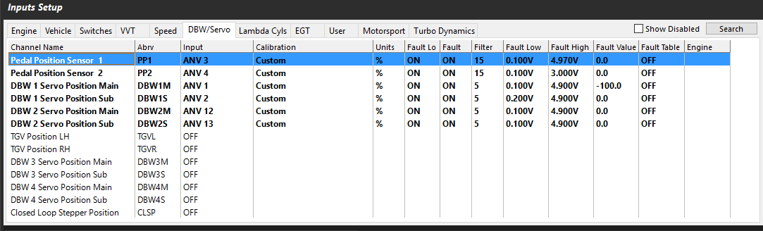
For safety reasons, there are redundant inputs for pedal position and drive by wire servo position. Once the sensors are setup and calibrated, these positions are used to define the DBW target in closed loop.
There are pre-configured functions to help quickly calibrate the pedal position sensors, and throttle position sensors. See
Each DBW Channel has 2 dedicated inputs for Position Feedback. These are:
DBW 1 Channel Position Feedback
DBW 1 Servo Position Main = Analog Volt 1 - 16
DBW 1 Servo Position Sub = Analog Volt 1 – 16
*Or Maximum ANV channel count depending on ECU model
DBW 2 Channel Position Feedback
DBW 2 Servo Position Main = Analog Volt 1 - 16
DBW 2 Servo Position Sub = Analog Volt 1 – 16
DBW 3 Channel Position Feedback
DBW 3 Servo Position Main = Analog Volt 1 - 16
DBW 3 Servo Position Sub = Analog Volt 1 – 16
DBW 4 Channel Position Feedback
DBW 4 Servo Position Main = Analog Volt 1 - 16
DBW 4 Servo Position Sub = Analog Volt 1 – 16
Input Pedal Position Channels
Pedal Position 1 = Analog Volt 1 - 16
Pedal Position 2 = Analog Volt 1 - 16
Sensor Calibration
The positioning sensors for the system must be calibrated like any other sensor. This can be done manually using the Calibration Table or there is an auto calibrate function described below.
Auto Calibration of Pedal Sensors
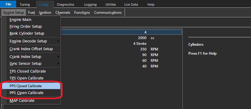
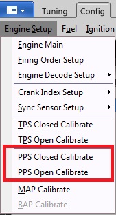
See the following menu: Config View -> Engine Setup -> PPS closed and PPS open calibrate.
Throttle Position Input Channel
The Throttle Position Input channel is NOT required in DBW applications as the DBW uses Servo Positions Inputs; the Throttle Position Input channel can be switch OFF.
The ECU will automatically copy the DBW 1 Servo Position Main into the Throttle Position 1 runtime.
This will allow functions requiring this input (gauges, logging, ORFC, Lockouts) to continue working.
DBW 1/2 Configuration
DBW 1/2 Configuration
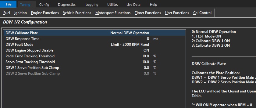
DBW Calibrate Plate
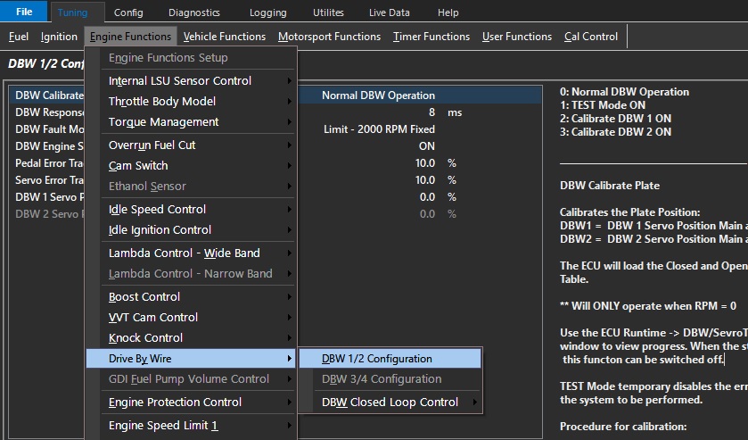
See the following menu: Tuning View-> Engine Functions -> Drive By Wire -> DBW 1/2 (or 3/4) Configuration
The following options are available:
0: Normal DBW Operation
1: TEST Mode ON
2: Calibrate DBW 1 ON
3: Calibrate DBW 2 ON
Modes 2 and 3 will calibrate the Plate Position (Servo Position):
The auto calibrate procedure populates the sensor calibration tables under input channels automatically for both fully closed and fully open positions.
NOTE:
** Will ONLY operate when RPM = 0
** TEST Mode temporarily disables the error checking allow final checks on the system to be performed
** Under no conditions should the vehicle be driven with the DBW system in TEST Mode.
** Calibrate Plate will not be possible where the Servo Position (Sub) reading clamps before complete blade deflection – Manual calibration will be required in this case.
Procedure for calibration:
Select which plate you need to calibrate (DBW1/2, or DBW 3/4)
Input pins for DBW Servo Positions must be enabled and setup correctly.
The ECU will move the throttle plate and calibrate the open and closed positions.
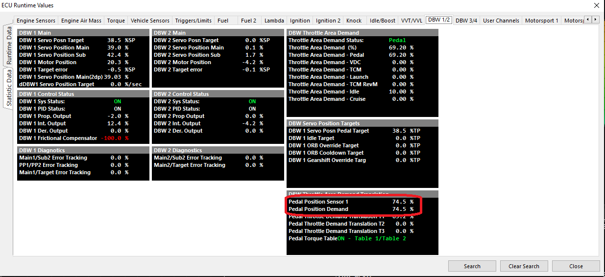
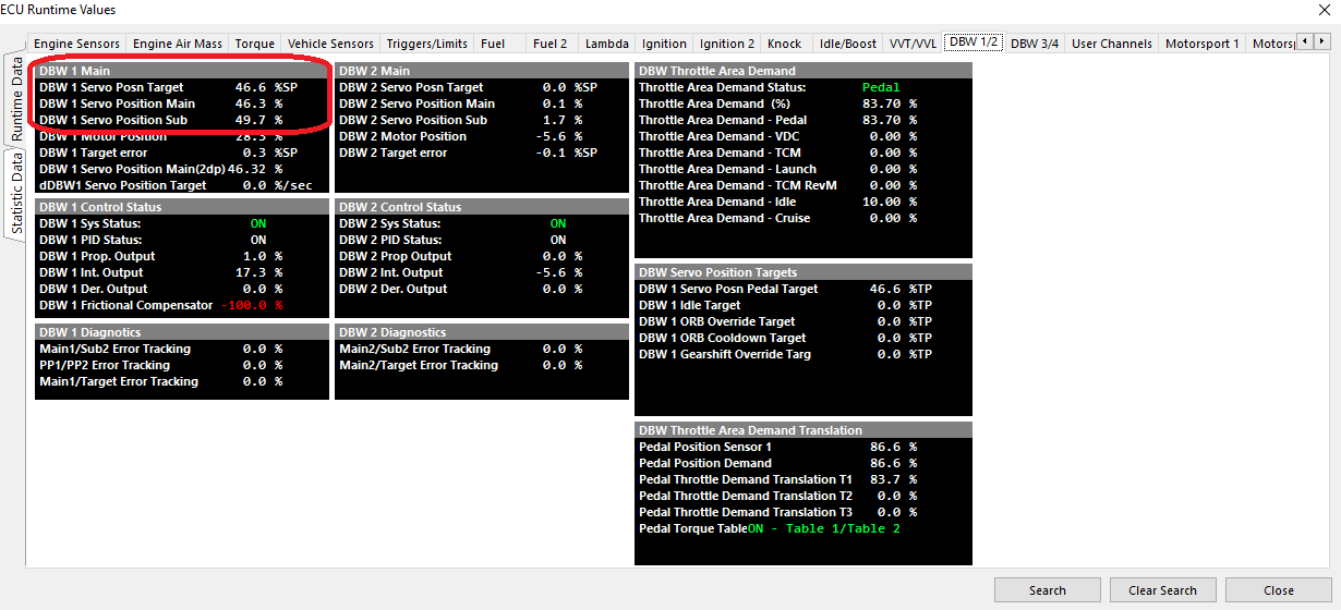
Use the ECU Runtime (F3) -> DBW/Sevro Tab -> DBW 1/2/3/4 - System Status window to view progress.
When the status reads “Calibrate Complete” , the DBW Calibrate Plate setting to can switched to “TEST Mode ON”.
This allows PID plate control but disables ALL tracking and safety features allowing PID calibration.
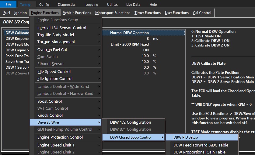
For PID control see Tuning View-> Engine Functions -> Drive By Wire -> DBW Closed Loop Control
Once the PID has been calibrated and the DBW Servo Position inputs are tracking correctly the TEST mode can be disabled.
Select DBW 1/2 Plate Calibration back to Normal mode.
DBW Response Time
The response time is the time from a commanded input change to the output changing.
Typical Time: 8 -12ms
DBW Fault mode
Emtron has an added layer of protection regarding a DBW fault (Servo position tracking, Target error, etc). The user can further define the engine behavior here.
DBW Fault Mode
0: Limit - 2000 RPM Fixed
1: Limp Home Table 1
2: Limp Home Table 2
In the case of a mechanically blocked throttle plate for example, even if the DBW system power supply is shut down, the engine could still run away.
This extra layer of protection allows the ECU to limit the engine RPM as well.
This makes a DBW system used with the Emtron product safer than even a cable operated system in regards to mechanical situation where a throttle is physically blocked open.Throttle Position Input Channel
The Throttle Position Input channel is NOT required in DBW applications as the DBW uses Servo Positions Inputs; the Throttle Position Input channel can be switch OFF.
The ECU will automatically copy the DBW 1 Servo Position Main into the Throttle Position 1 runtime. This will allow functions requiring this input (gauges, logging, ORFC, Lockouts) to continue working.
DBW Engine Stopped Disable
When the engine is stopped (RPM = 0 ) and Pedal Position is < 0.5% the DBW system can be disabled.
(Prevents battery drain with prolonged key-on use)
As soon as a Crank Signal is detected or the pedal moves > 0.5% the system becomes active again.
Pedal Error Tracking Threshold
When the difference between Pedal Position 1 and 2 is greater than the threshold, the ECU determines this to be an error condition and and increments a Error Counter.
The greater the difference, the faster the counter increments.
DBW Shutdown condition occurs when Error Counter reaches 100.
Typical 5.0%
Since the pedal position is validated by redundant inputs, once calibrated the position values can be compared and ultimately shutdown the DBW system if a sensor is failing.
The threshold here can be adjusted for the minimum amount of error needed for Error Tracking to start counting.
NOTE"
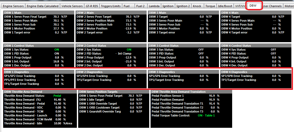
** Once “Error Tracking” for Pedal Position (PP) or Servo Position (SP) reaches 100%, the DBW system will be shut down and remain shutdown until the ECU power is cycled.
The Error Tracking rate is proportional to error so the bigger the error the faster the counter increments .
Servo Error Tracking Threshold
When the difference between DBW Servo Position Main and Sub is greater than the threshold, the ECU determines this to be an error condition and and increments a Error Counter.
The greater the difference, the faster the counter increments.
DBW Shutdown condition occurs when Error Counter reaches 100.
Typical 5.0%
DBW 1 Servo Position Sub Clamp
Used in applications when the DBW 1 Servo Position Sub signal does not span the full movement of the throttle plate.
Enter in the maximum %Servo Position as seen when the plate is fully open.
Typical applications include the Ford BA/BF/FG where this value is 51.0%
In normally applications set to 100% or
0 = OFF
DBW 2 Servo Position Sub Clamp
Used in applications when the DBW 2 Servo Position Sub signal does not span the full movement of the throttle plate.
Enter in the maximum %Servo Position as seen when the plate is fully open.
Typical applications include the Ford BA/BF/FG where this value is 51.0%
In normally applications set to 100% or
0 = OFF
DBW Calibration Guide
Steps to Calibrating and Tuning DBW
Set up Output and Input configuration functions for your ECU type as instructed here -> Drive by Wire (DBW)
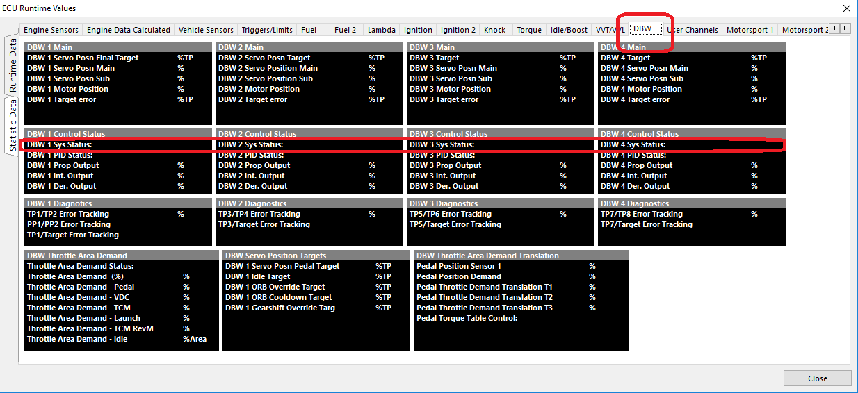
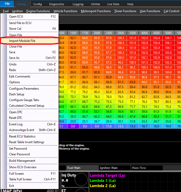
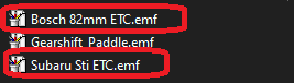
Once Inputs and Outputs are set up, select a “Module File” that is closest to your throttle system
This will pre-populate all basic settings for DBW throttle PID, response time, delay, etc.
Validate the Pedal is channels are tracking correctly in Runtimes (F3)
Calibrate DBW positions using Auto Calibrate Procedure, See “DBW Calibrate Plate” here -> DBW 1/2 Configuration
Validate the DBW Servo Position channels are tracking correctly in Runtimes (F3)
Adjust PID to suit the throttle if is not moving/tracking appropriately -> DBW Closed Loop tables
DBW Closed Loop Control - DBW PID Setup
DBW PID Setup
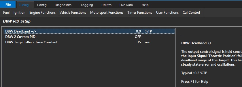
DBW Deadband +/-
The output control signal is held constant when the Input Signal (Throttle Position) falls within the deadband range of the Target.
This helps reduce steady state error and oscillations.
Typical : 0.2 %TP
DBW 2 Custom PID
If a second DBW servo is used that is of a different type, then the PID can be customized separately.
This enables configuration tables for DBW 2
** Most commonly used when a DBW servo is used for bypassing air for a turbocharged or supercharged vehicle (DBW Air Bleed)
0: OFF
1: ON
DBW Target Filter - Time Constant
Low pass digital filter Time Constant characterizes the speed taken to respond to a step input.
The value entered represents the time (in ms) it takes for the output to reach 63% of the stepped input value.
For example if the step input changed occurred from 0 - 50.0% and the Time Constant was 25ms, the filtered output would reach 31.5% after 25ms.
Tuning DBW PID
DBW servo position is controlled in the Torque Management section -> Pedal Demand.
See Torque Management – Throttle Mass Flow
See Torque Management – Pedal to Throttle Demand
DBW Closed Loop tables
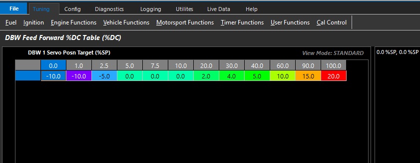
DBW Feed Forward %DC Table
Emtron uses a Feed Forward Table to provide a base duty for the PID function to operate from.
This allows for very fast response as the ECU has an initial lookup table before any PID is applied.
This table can be expanded into 3D (X axis enabled), and any runtime can be used.
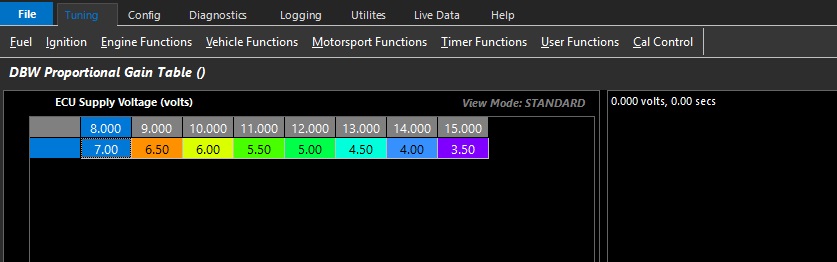
DBW Proportional Gain Table
Proportional gain controls how aggressive instantaneous correction must be.
This table can be expanded into 3D (X axis enabled), and any runtime can be used.
Above is an example where the change Proportional Gain is spanned across Battery Voltage.
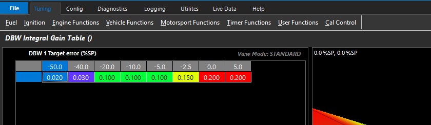
DBW Integral Gain Table
Integral gain controls how much adaptive correction is needed.
This table can be expanded into 3D (X axis enabled), and any runtime can be used.
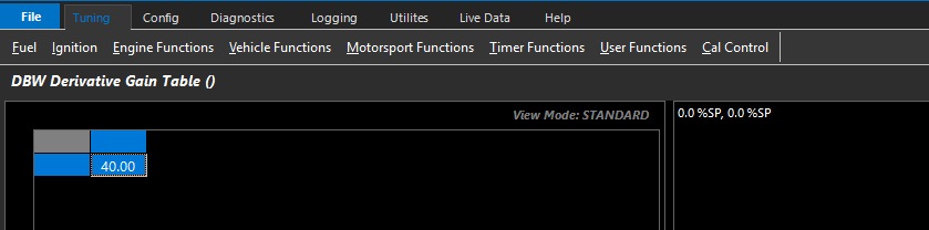
DBW Derivative Gain Table
Derivative gain controls predictive correction where gain is based on the rate of change of error.
This function is used to prevent overshooting targets by looking at a number of factors like rate of change, and P and I gain.
This table can be expanded into 3D (X axis enabled), and any runtime can be used.
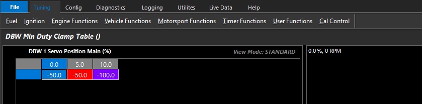
DBW Min Duty Clamp Table
Allows the user to set the minimum duty cycle that can be used by the closed loop system.
This table can be expanded into 3D (X axis enabled), and any runtime can be used.
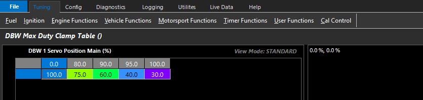
DBW Max Duty Clamp Table
Allows the user to set the maximum duty cycle that can be used by the closed loop system.
This table can be expanded into 3D (X axis enabled), and any runtime can be used.
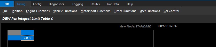
DBW Pos Integral Limit Table
Allows the user to set the maximum I gain compensation used by the closed loop system.
This table can be expanded into 3D (X axis enabled), and any runtime can be used.
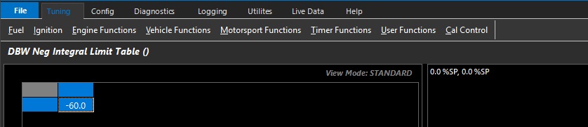
DBW Neg Integral Limit Table
Allows the user to set the minimum I gain compensation used by the closed loop system.
This table can be expanded into 3D (X axis enabled), and any runtime can be used.
NOTE:
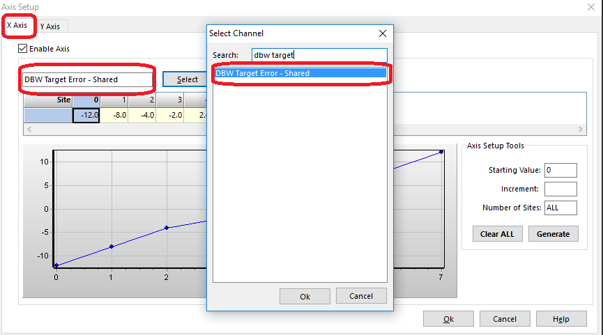
** If using dual DBW, then axis for target errors should be selected as “shared” runtimes. This tells the PID system to look at the respective DBW to apply closed loop gains
Tuning DBW PID
The DBW servo position is controlled in the Torque Management section.
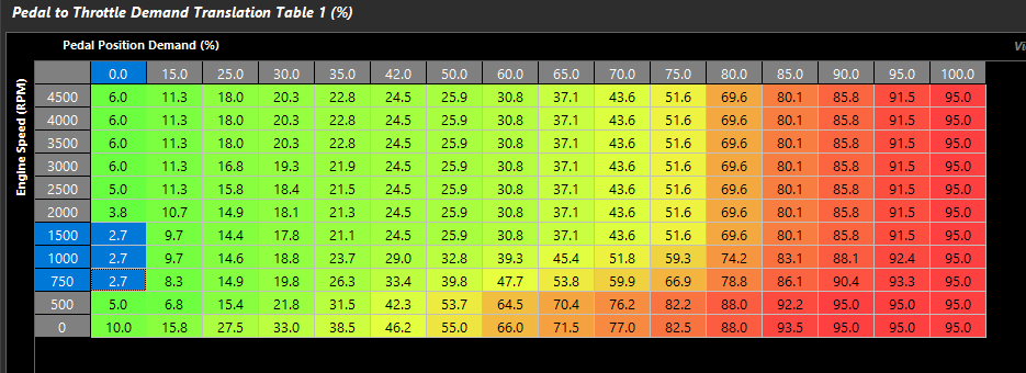
The Pedal to Throttle Area Demand Translation Tables control the driver demand translation into throttle area demand.
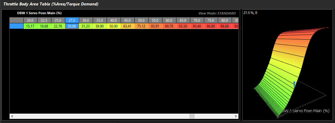
The relationship between throttle area demand & DBW servo position is validated in Throttle Body Model > Throttle Body Area Table
The Pedal to Throttle Area Demand Translation Table does not relate to DBW servo position directly
To tune the DBW PID, it is useful to reconfigure the target function & zero the Pedal Position Demand Filter
For the purpose of tuning the PID, change the Pedal to Throttle Area Demand Translation Tables and the Throttle Body Area Table to be linear.
This will deliver a 1:1 relationship
Once PID control is validated, return to non linear Pedal to Throttle Area Demand Translation Tables & validate the Throttle Body Area Table
See Torque Management – Throttle Mass Flow
See Torque Management – Pedal to Throttle Demand Translation Table
See Throttle Body Setup - Throttle Body Area Table
DBW Input Setup
Filter Settings
FIlter Setting Minimum = 0 (OFF)
FIlter Setting Maximum = 100
Recommended Filter Range = 2 - 5
Single DBW.
When using single DBW the following 4 inputs should be used. Although these inputs have no restrictions on their input assignment, the following is recommended.
DBW 1 Servo Position Main = Analog Volt 1
DBW 1 Servo Position Sub = Analog Volt 2
Pedal Position 1 = Analog Volt 13
Pedal Position 2 = Analog Volt 14
Dual DBW.
When using Dual DBW the following 6 inputs should be used. Although these inputs have no restrictions on their input assignment, the following is recommended.
DBW 1 Servo Position Main = Analog Volt 1
DBW 1 Servo Position Sub = Analog Volt 2
DBW 2 Servo Position Main = Analog Volt 3
DBW 2 Servo Position Sub = Analog Volt 4
Pedal Position 1 = Analog Volt 13
Pedal Position 2 = Analog Volt 14
DBW Pedal Position (PP) Calibration
Two options are available:
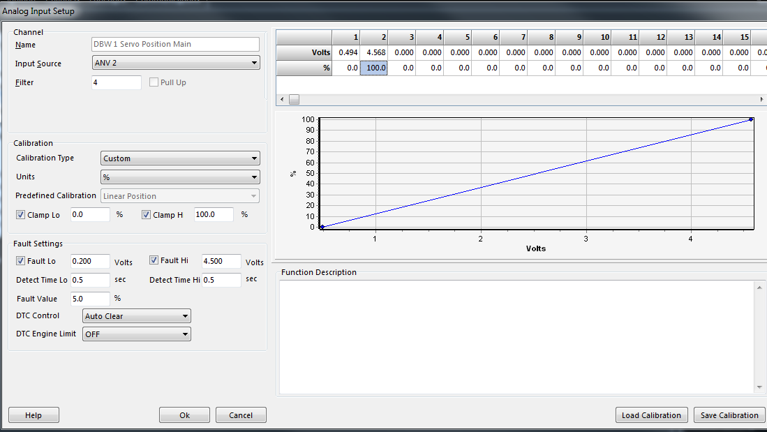
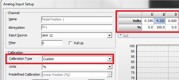
Manually enter in the Open and Closed voltages into each Calibration Table. Select Calibration Type to “Custom” and enter the value into the table as shown.
Automatic Calibration. Use the PP Closed/Open Calibration menu to automatically set these voltages. This can be access from Config View-> Engine Setup as shown.
When selected the PP1 and PP2 voltages will be written into their corresponding calibration tables. Make sure these channels have an Input Source set before selecting these menus.
These voltages can be viewed be going back to the Input Setup form as shown above.
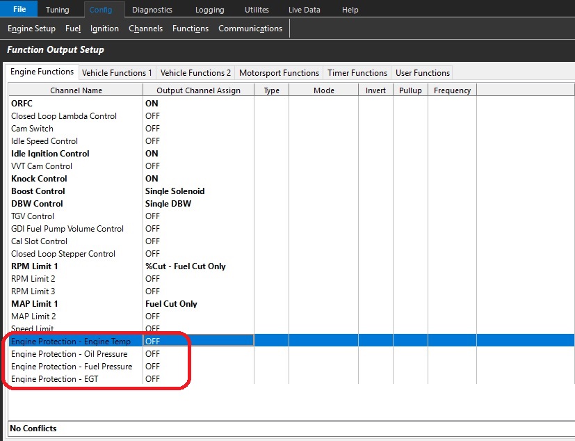
Each function must be enabled and cut type selected to become active.
(Fuel or Ignition Cut) - Fuel Cut is recommended
Once active, each function must be defined for correct operation.
Further engine protection can be defined by the user through the use of user functions and or timers.
Fuel Pressure 1 Differential Offset runtime
The Fuel Pressure 1 Differential Offset runtime reports the offset value in kPa between calculated and measured differential pressure.
Fuel Pressure sensor is required
.
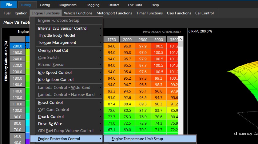
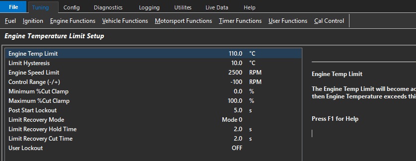
Engine Temperature Limit Setup
Engine Temp Limit
The Engine Temp Limit will become active then Engine Temperature exceeds this value.
Limit Hysteresis
Engine Temperature must return to the (Limit Value - Hysteresis Value) for the “Recovery Hold Time” entered before the Limit is switched OFF.
Engine Speed Limit
Engine speed limit applied when limit is active
Control Range (-/+)
Engine Speed Limit control range in RPM when limit is active
Minimum %Cut Clamp
Percentage cut applied to the engine at the start of the control range.
The cut type is defined in the Function Output.
Maximum %Cut Clamp
Percentage cut applied to the engine at the end of the control range
The cut type is defined in the Function Output.
Post Start Lockout
Will prevent the limit operating during crank and for a time after the engine has started.
Limit Recovery Mode
Controls the limit exit strategy.
Mode 0: Engine Temp < (Target Limit - Hysteresis) for the specified Hold Time.
Mode 1: Engine Temp < Target Limit - Hysteresis) for the specified Hold Time.
AND Engine Speed must have reached the Engine Speed Limit.
0: Mode 0
1: Mode 1
Limit Recovery Hold Time
When the Engine Protection limit is activated a time delay can be applied before the engine can recover.
This to prevent premature engine recovery from an Engine Protection event.
Limit Recovery Cut Time
Allow the cut to be progressively removed from the engine.
User Lockout
Allows the user to Lockout the Limit.
When the selected User Channel is ON a Limit request will still be generated but the engine will not be limited. ie %Cut will be zero.
Used for situations when you want to generate a Limit Request but not actually limit/cut the engine.
0: OFF
1: User Channel 1
2: User Channel 2
3: User Channel 3
4: User Channel 4
5: User Channel 5
6: User Channel 6
7: User Channel 7
8: User Channel 8
9: User Channel 9
10: User Channel 10
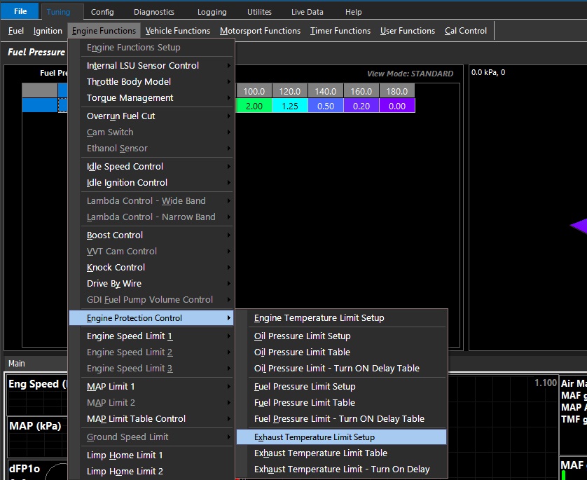
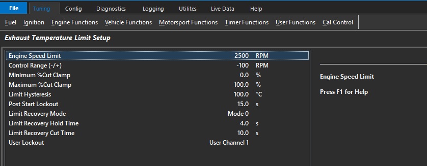
Exhaust Temperature Limit Setup
Engine Speed Limit
Engine speed limit applied when limit is active
Control Range (-/+)
Engine Speed Limit control range in RPM when limit is active
Minimum %Cut Clamp
Percentage cut applied to the engine at the start of the control range.
The cut type is defined in the Function Output.
Maximum %Cut Clamp
Percentage cut applied to the engine at the end of the control range
The cut type is defined in the Function Output
Limit Hysteresis
Exhaust Temperature must return to the (Limit Value + Hysteresis value) for the “Recovery Hold Time” entered before the Limit is switched OFF.
Post Start Lockout
Will prevent the limit operating during crank and for a time after the engine has started.
Limit Recovery Mode
Controls the limit exit strategy.
Mode 0: Exhaust Temperature > (Target Limit Temperature + Hysteresis) for the specified Hold Time.
Mode 1: Exhaust Temperature > (Target Limit Temperature + Hysteresis) for the specified Hold Time.
AND Engine Speed must have reached the value in the Engine Speed Limit setting
0: Mode 0
1: Mode 1
Limit Recovery Hold Time
When the Engine Protection limit is activated a time delay can be applied before the engine can recover.
This to prevent premature engine recovery from an Engine Protection event.
Limit Recovery Cut Time
Allow the cut to be progressively removed from the engine.
User Lockout
Allows the user to Lockout the Limit.
When the selected User Channel is ON a Limit request will still be generated but the engine will not be limited. ie %Cut will be zero.
Used for situations when you want to generate a Limit Request but not actually limit/cut the engine.
0: OFF
1: User Channel 1
2: User Channel 2
3: User Channel 3
4: User Channel 4
5: User Channel 5
6: User Channel 6
7: User Channel 7
8: User Channel 8
9: User Channel 9
10: User Channel 10
Exhaust Temperature Limit Table
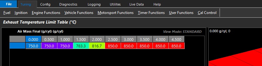
User defined Exhaust Temperature limit table. Limit is active above Deg C input values.
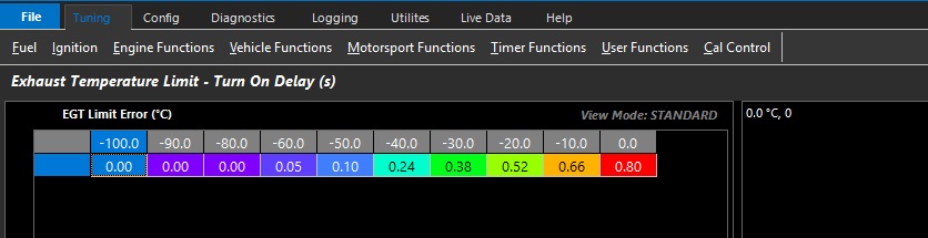
Exhaust Temperature Limit - Turn ON Delay Table (Sec)
User defined limit activation delay table in seconds.
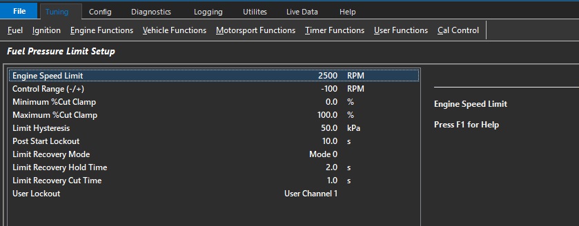
Fuel Pressure Limit Setup
Engine Speed Limit
Engine speed limit applied when limit is active
Control Range (-/+)
Engine Speed Limit control range in RPM when limit is active
Minimum %Cut Clamp
Percentage cut applied to the engine at the start of the control range.
The cut type is defined in the Function Output.
Maximum %Cut Clamp
Percentage cut applied to the engine at the end of the control range
The cut type is defined in the Function Output
Limit Hysteresis
Fuel Pressure must return to the (Limit Value + Hysteresis value) for the “Recovery Hold Time” entered before the Limit is switched OFF.
Post Start Lockout
Will prevent the limit operating during crank and for a time after the engine has started.
Limit Recovery Mode
Controls the limit exit strategy.
Mode 0: Fuel Pressure > (Target Limit Pressure + Hysteresis) for the specified Hold Time.
Mode 1: Fuel Pressure > (Target Limit Pressure + Hysteresis) for the specified Hold Time.
AND Engine Speed must have reached the value in the Engine Speed Limit setting
0: Mode 0
1: Mode 1
Limit Recovery Hold Time
When the Engine Protection limit is activated a time delay can be applied before the engine can recover.
This to prevent premature engine recovery from an Engine Protection event.
Limit Recovery Cut Time
Allow the cut to be progressively removed from the engine.
User Lockout
Allows the user to Lockout the Limit.
When the selected User Channel is ON a Limit request will still be generated but the engine will not be limited. ie %Cut will be zero.
Used for situations when you want to generate a Limit Request but not actually limit/cut the engine.
0: OFF
1: User Channel 1
2: User Channel 2
3: User Channel 3
4: User Channel 4
5: User Channel 5
6: User Channel 6
7: User Channel 7
8: User Channel 8
9: User Channel 9
10: User Channel 10
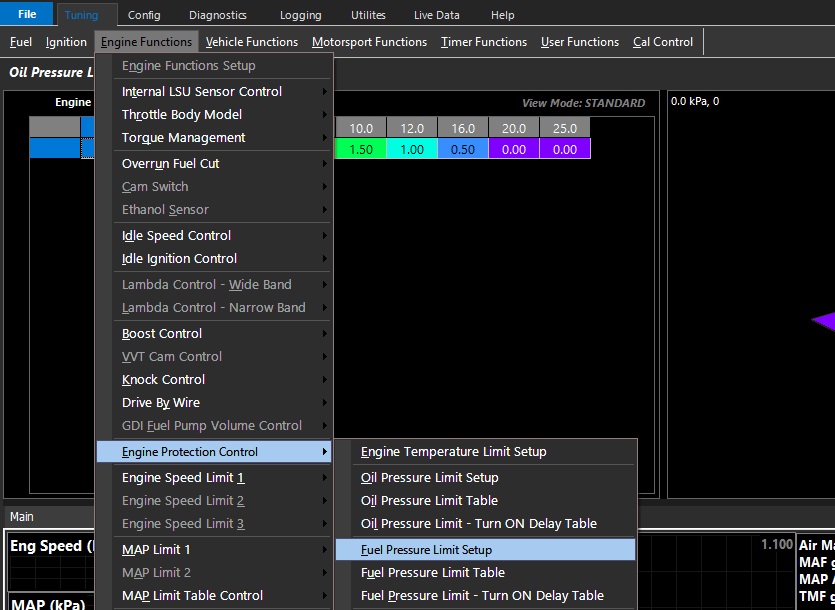
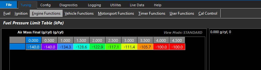
Fuel Pressure Limit Table
User defined Fuel differential offset pressure limit table. Limit is active below the offset kPa input values.
Fuel Pressure 1 Differential Offset runtime value is utilised
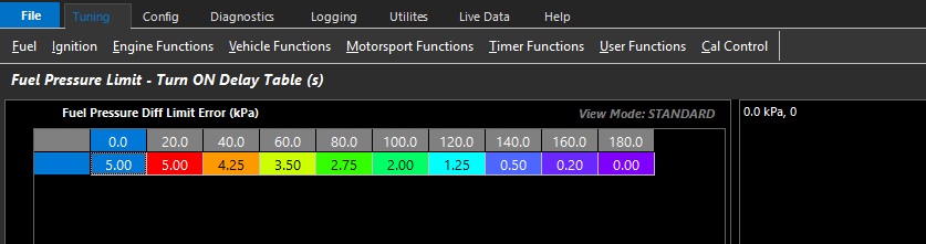
Fuel Pressure Limit - Turn ON Delay Table (Sec)
User defined limit activation delay table in seconds.
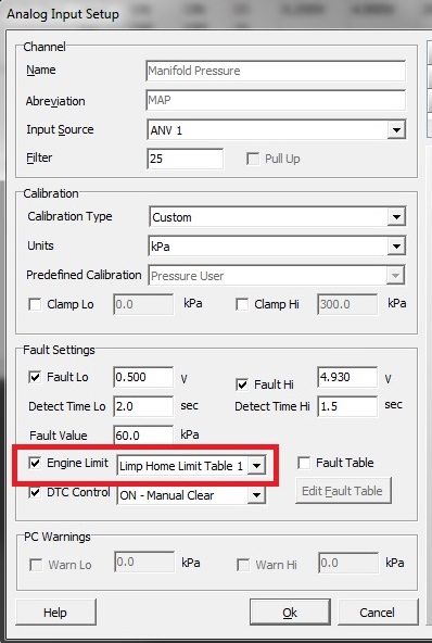
Limp Home Limits
This function provides Engine Speed Limiting when a DTC error occurs on an Input Channel. The operation of these table(s) can be controlled independently from each Input Channel setup page.
The following settings are not adjustable:
Start Cut - Set at 50%
End Cut - Set at 95%
Control Range = Set at +200 RPM
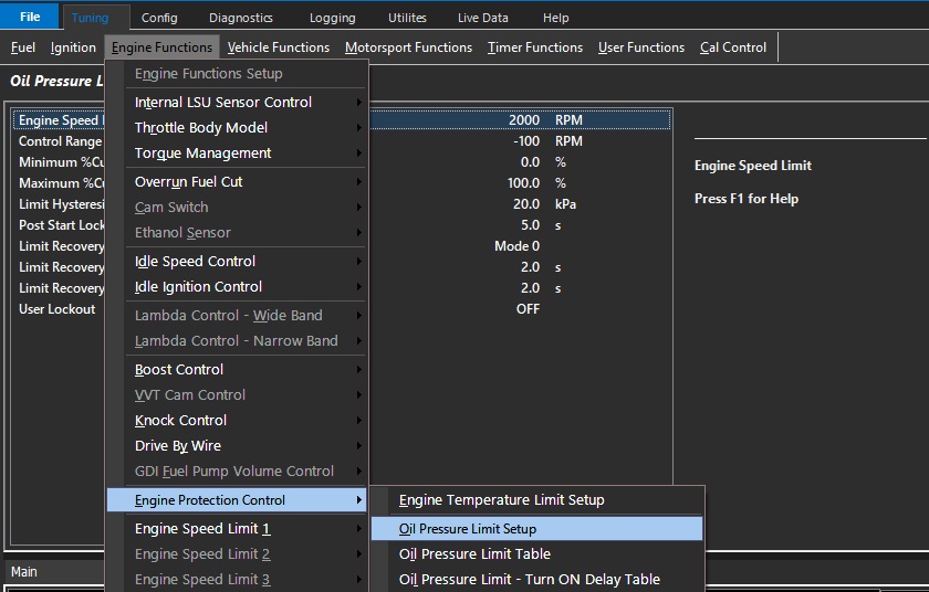
Oil Pressure Limit Setup
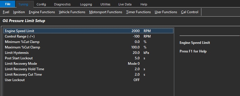
Engine Speed Limit
Engine speed limit applied when limit is active
Control Range (-/+)
Engine Speed Limit control range in RPM when limit is active
Minimum %Cut Clamp
Percentage cut applied to the engine at the start of the control range.
The cut type is defined in the Function Output.
Maximum %Cut Clamp
Percentage cut applied to the engine at the end of the control range
The cut type is defined in the Function Output
Limit Hysteresis
Oil Pressure must return to the (Limit Value + Hysteresis value) for the “Recovery Hold Time” entered before the Limit is switched OFF.
Post Start Lockout
Will prevent the limit operating during crank and for a time after the engine has started.
Limit Recovery Mode
Controls the limit exit strategy.
Mode 0: Oil Pressure > (Target Limit Pressure + Hysteresis) for the specified Hold Time.
Mode 1: Oil Pressure > (Target Limit Pressure + Hysteresis) for the specified Hold Time.
AND Engine Speed must have reached the value in the Engine Speed Limit setting
0: Mode 0
1: Mode 1
Limit Recovery Hold Time
When the Engine Protection limit is activated a time delay can be applied before the engine can recover.
This to prevent premature engine recovery from an Engine Protection event.
Limit Recovery Cut Time
Allow the cut to be progressively removed from the engine.
User Lockout
Allows the user to Lockout the Limit.
When the selected User Channel is ON a Limit request will still be generated but the engine will not be limited. ie %Cut will be zero.
Used for situations when you want to generate a Limit Request but not actually limit/cut the engine.
Example: During a Launch the Oil Pressure may temporally drop below the Limit Target.
A User Channel can be configured to lockout this limit during the first stages of Launch Control.
0: OFF
1: User Channel 1
2: User Channel 2
3: User Channel 3
4: User Channel 4
5: User Channel 5
6: User Channel 6
7: User Channel 7
8: User Channel 8
9: User Channel 9
10: User Channel 10
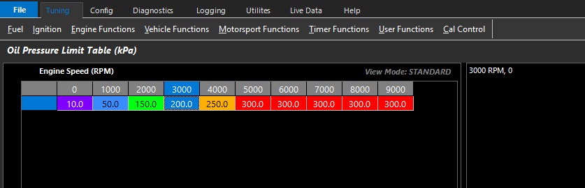
Oil Pressure Limit Table
User defined oil pressure limit table. Limit is active above kPa input values.
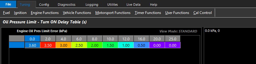
Oil Pressure Limit - Turn ON Delay Table (Sec)
User defined limit activation delay table in seconds.
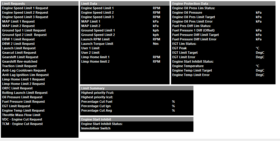
The following calculated runtimes are generated by Emtron that are Engine Speed Limit/Cut related (to be further discussed more specifically):
** Highest priority Fcut and Highest priority Icut Runtimes will always show the active limit request. It is highly recommended to always have these channels in the ECU logger.
The Limit with the highest percentage cut ALWAYS get priority over other pending limits. This also means any Ignition or Fuel adjustments associated with the function also get priority.
So ONLY 1 limit can be active at any one time.
Functions that can limit the engine are:
Engine Speed Limit 1
Engine Speed Limit 2
Engine Speed Limit 3
MAP Limit 1
MAP Limit 1
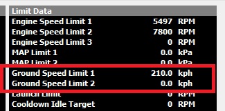
Ground Speed Limit 1
Ground Speed Limit 2
Launch Limit
Gear Cut
Traction Control Limit
Anti-Lag Cut
Anti-Lag cool down
DBW Safety Limit
Limp Home Limit 1
Limp Home Limit 2
Example. RPM limit is currently active.
RPM LImit 1 = 60% Cut
RPM Limit 1 Ignition retard = 15 Deg
Then get a Gear Cut request is generated:
Gear Cut = 90% Cut
Gear Cut Ignition retard = 20 Deg.
The ECU will stop the RPM limit1, remove the 15 degree of retard, activate a 90% cut and apply 20 degrees retard.
RPM Limit Function Setup
Emtron has three different RPM Limiters and four different methods for each
Config, Function Setup, Engine Functions, RPM Limit 1/2/3
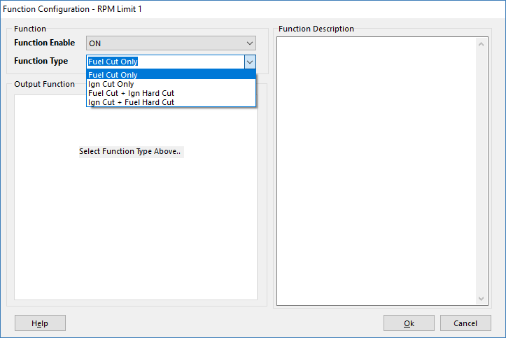
Select the cut type and order of priority for each RPM limit function
Engine Speed Limiter Setup
Engine Speed Limiter Setup
Cut Pattern
Select the cut pattern type
.
0: Random Pattern 1
1: Random Pattern 2
2: Sequential Pattern 1
3: Sequential Pattern 2
Ign Retard Mode
Applies the Ignition Retard as either an Offset or Percentage of Base Angle (Table value)
Example: Current Ignition Angle = 25.0 BTDC
Offset = 15.0 Deg Retard. Ignition Angle During
Limiting = 25.0 - 15.0 = 10.0 Deg BTDC
Percentage = 50.0 % Retard.
Ignition Base Angle = 20.0 Deg.
Ignition Angle During Limiting = 20 - 50% x 20.0 = 10.0 Deg BTDC
(assuming no other Ignition trims)
Control Range
Control Range (-/+) RPM Units
The Control Range applies to the Min/Max % Cut values
Example :
Min % Cut Clamp 10%
Max % Cut Clamp 90%
Control Range -200rpm
RPM Limit 7000rpm
At 6800rpm the engine will begin its cut routine at the Min % Cut Clamp of 10%
At 7000rpm the engine will finish its cut routine at the Max % Cut Clamp of 90%
Minimum %Cut Clamp
Percentage cut applied to the engine at the start of the control range.
Maximum %Cut Clamp
Percentage cut applied to the engine at the end of the control range.
NOTE: Maximum Cut MUST be > Minimum Cut
Hard Limit Adder
Used in Limit types 2 and 3.
Added to the start on the limit and determines the point at which a 100% cut will be applied.
Example:
Limit Type = 2 (Fuel Cut + Ign Hard Cut)
RPM Limit = 7000
Control Range = -200 RPM
Hard Limit Adder = 180 RPM
Fuel %cut Engine Limiting starts at 6800 at the Minimum %Cut
Fuel %cut Engine Limiting ends at 7000 at the Maximum %Cut
Ign 100% cut occurs at 6980 RPM and above.
dRPM Gain
Compensates for a fast rate of change in engine speed by reducing the limit value.
Used to prevent the engine pushing through the limit.
Locked out when dRPM < 2000 RPM/sec.
A Gain of 100 will reduce the limit by 100 RPM for every dRPM 1000 RPM/sec over the 2000 start threshold.
Example 1:
dRPM Gain = 100
RPM limit = 6500
dRPM = 3000 RPM/sec
New RPM Limit = 6500 - 100 = 6400
Example 2:
dRPM Gain = 100
RPM limit = 6500
dRPM = 4000 RPM/sec
New RPM Limit = 6500 - 200 = 6300
0 = OFF
Ignition Retard
The amount of Ignition Retard applied during limiting.
There are 2 modes :
Offset (Deg)
Percentage (%)
Post Start Lockout
Will prevent the limit operating during crank and for a time after the engine has started.
Useful when channels like oil pressure are assigned to an RPM limiter function.
** Using the Engine Protection Control function is highly recommended instead
RPM Limit - Turn ON Delay Table
RPM Limit - Turn ON Delay Table
Table in which you can set the delay for the RPM limit
Units in Seconds
RPM Limit - User 1/2 Offset Table
RPM Limit - User 1/2 Offset Table
Table in which you can offset the main RPM limit table +/-15000 RPM.
Span this table using any Emtron calculated runtime like Rotary Position, Race Timer, User Timer, etc.
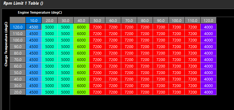
RPM Limit Table
RPM Limit Table
Engine Start Control
Overview
This function controls both Engine Starter Function output and Immobiliser Function.
The Engine Start Function will switch an Output ON to start the engine cranking. The ECU Output would normally be connected to the Starter Relay. Once the ECU determines the engine is running the relay will be switched OFF.
NOTE: Both an Input and Output Channel MUST be selected for the Engine Start function to work.
The Immobiliser Function prevents Fuel and Ignition occurring while the Immobiliser Function is active. An Output can also be configured to further enhance this function. For example you might want to inhibit the starter relay operating.
Engine Start Function
Input Channel
One of two Inputs can be configured to control this function:
Start/Stop Switch. (See Config View -> Input Pins Setup -> Switches Tab). With this Input the Switch can Start and Stop the Engine
Start Position Switch. (See Config View -> Input Pins Setup -> Switches Tab). This Switch will ONLY Start the engine.
When the engine speed is zero and the button is pressed the ECUs interprets this as a request to START the engine. At this point the ECU will switch ON the Starter Relay. During the “Cranking Timeout” period the ECU will monitor Engine Speed and when it exceeds the “Engine Started RPM” the Starter Relay will be switched OFF. If the “Cranking Timeout” period is reached and the engine has not started the Starter Relay will be switched OFF.
When the engine is running and the button is pressed the ECUs interprets this as a request to STOP the engine. The ECU will switch OFF Fuel and Ignition until the Engine Speed has reached zero.
2. Starter Relay Output - Input Switch Configured as “Start Position Switch”:
When the engine speed is zero and the button is pressed the ECUs interprets this as a request to START the engine. At this point the ECU will switch ON the Starter Relay. During the “Cranking Timeout” period the ECU will monitor Engine Speed and when it exceeds the “Engine Started RPM” the Starter Relay will be switched OFF. If the “Cranking Timeout” period is reached and the engine has not started the Starter Relay will be switched OFF.
This mode is more used in Motorsport applications. The Start Button starts the engine and the Main kill switch is used to shut the engine down and disconnect power from all systems.
NOTE: In this Mode the Switch CANNOT be used to STOP the engine when it is running. It is a Start ONLY function. However, there is a safety feature build; when the engine is cranking if engine needs to be stopped, pressing the Start button again will stop the engine cranking.
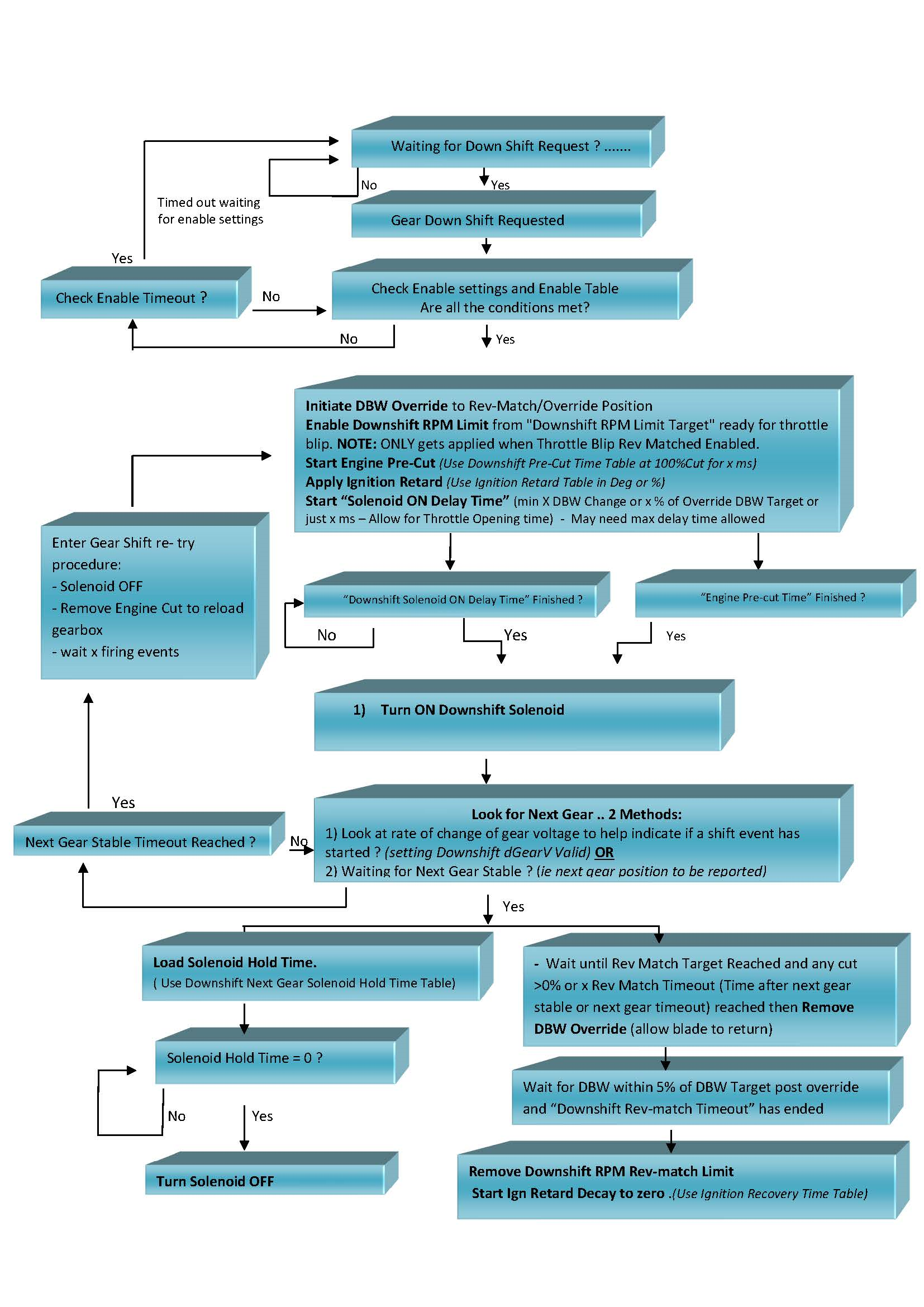
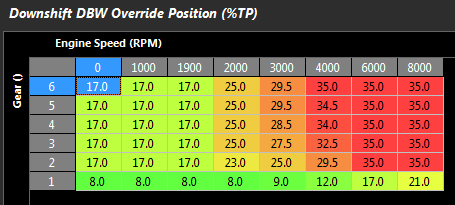
Sets the throttle position target that the DBW throttle will move to during the down shift.
This is an absolute position of the DBW Servo.
** This position will override other torque management functions regarding throttle control
Downshift Ignition Retard
Downshift Ignition Retard
This is the amount of Ignition Retard applied during the entire Downshift event
There are 2 modes :
Offset (Deg)
Percentage (%)
Downshift Next Gear Ignition Recovery Time
Downshift Next Gear Ignition Reovery Time
This is the total time the ignition retard will be phased back to 0.
Resolution = 1ms
Downshift Next Gear Solenoid Hold Time
Downshift Next Gear Solenoid Hold Time
This is the time the Solenoid stays ON once next gear stable has been achieved .
Resolution = 1ms
Downshift Pre-Cut Time
Downshift Pre-Cut Time
Engine Pre-Cut Time
Normally only required when the Throttle is held open on a downshift request. The Pre-cut allow the gearbox dog to be unloaded before the Downshift solenoid is switched ON. This allows the servo to be position before the power is re-applied for the downshift blip
0 = OFF
Downshift Request Enable Table
Downshift Request Enable Table
The Table output must be Enabled allowing the Downshift request to be valid.
(set to 100 if not required)
0 = Shift Request Disabled
100 = Shift Request Enabled
50 = No Change
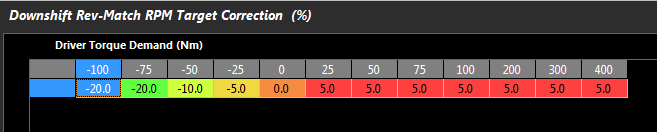
Downshift Rev-Match RPM Target Correction
Downshift Rev-Match RPM Target Correction
This table controls adjusts the Rev-Match RPM Target +/- in units of %.
Use this to raise or lower the Rev-Match RPM Target
Downshift Setup
Downshift Debounce Time
The Downshift Paddle must be held for this time for the request to be valid.
This setting prevents accidental requests in harsh Motorsport
environments (vibration and vehicle harmonics).
Downshift Torque Reduction Type
0: Fuel Cut Only
1: Ign Cut Only
2: Fuel + Ign Cut
3: Off
\
Downshift Ign Retard Mode
0: OFF
1: Offset
2: Percentage
Applies the Ignition Retard as either an Offset or Percentage of Current Ign Angle
Example: Current Ignition Angle = 20.0 BTDC
Offset = 15.0 Deg Retard.
Ignition Angle during Gear Cut is = 20.0 - 15.0 = 5.0 Deg BTDC
Percentage = 50.0 % Retard.
Ignition Angle During Cut : = 20 - 50% x 20.0 = 10.0 Deg BTDC
Downshift Pre-Cut Percentage Cut
Fuel and/or Ignition Cut Percentage used in the Downshift Precut.
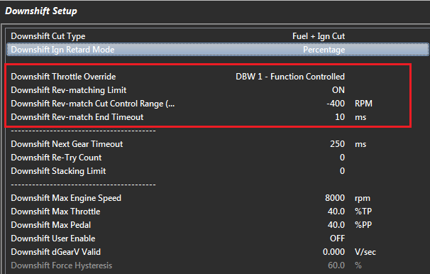
Downshift Throttle Override
0: OFF
1: DBW 1 - Duration Table
2: DBW 1 - Function Controlled
3: Throttle Solenoid - Duration Table
4: Throttle Solenoid - Function Controlled
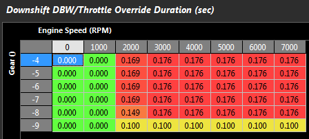
This setting overrides or “blips” the thottle on downshift .
Duration Table is Open Loop mode and used to control the length of time the DBW or Solenoid is held open.
Function Controlled is Closed Loop so the Gearshift
Function is used to control the length of time the DBW or Solenoid is held open.
The goal is to increase the airflow into the engine to match the engine speed of the requested downshift gear.
NOTE: The Rev-matching Limit setting can also be switched ON, which limits the engine to the correct rpm assuming enough air has benn introduced into the engine.
Downshift Rev-Matching Limit
0: OFF
1: ON - Outputshaft Speed
2: ON - Outputshaft Speed Calculated
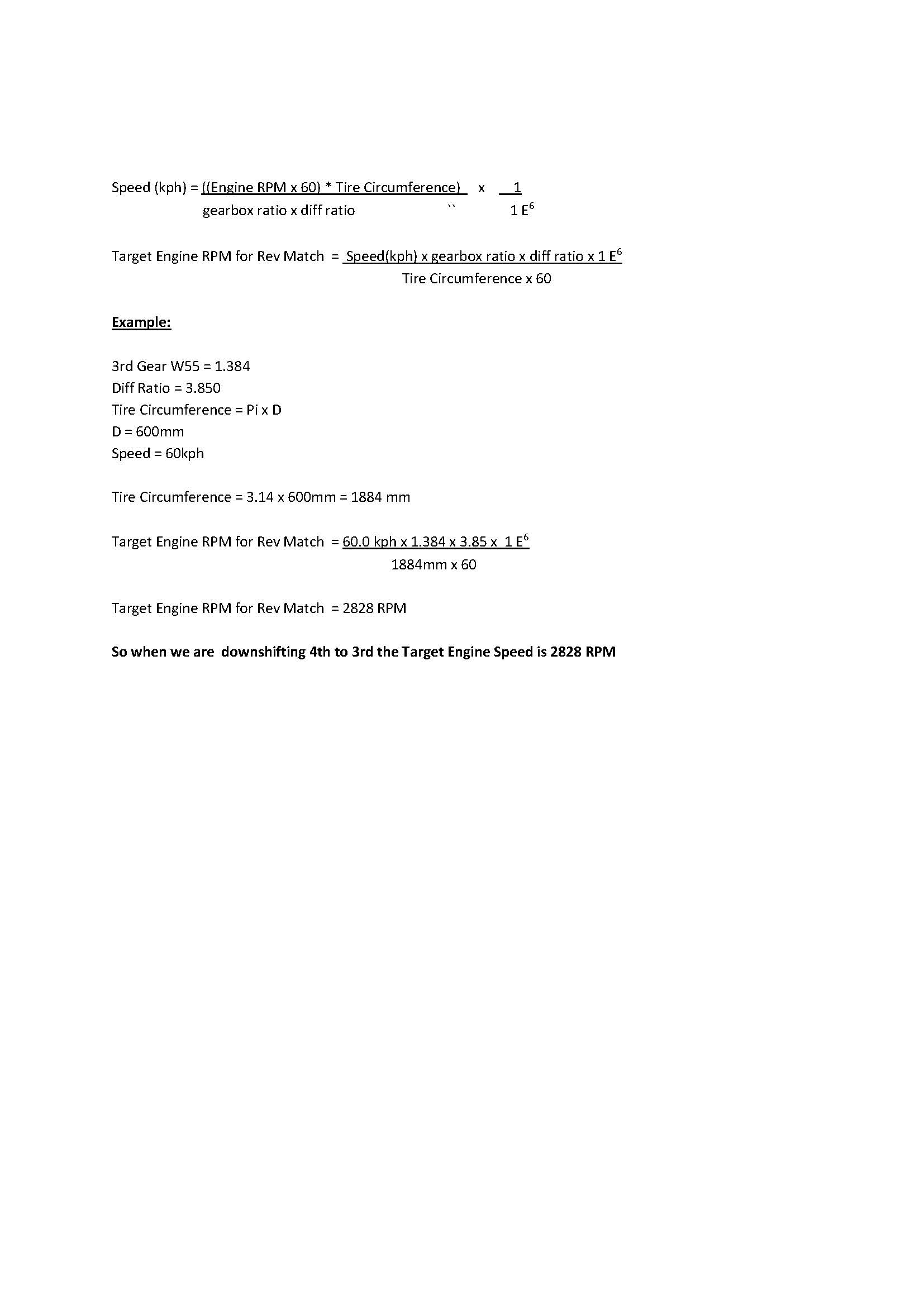
Rev-matching Downshift Function will Limit the engine RPM to match the requested Downshift gear. The ECU uses Output shaft RPM and Transmission ratios between the current gear and requested gear to calculate a Rev-matched RPM Target.
i.e. Matching Transmission Input and Output speed referenced by Gear Ratio
Make sure the “Downshift Rev-Match RPM Target Correction “table is setup/Initialised correctly
You also MUST introduce extra air into the engine either by using the DBW or a solenoid to manual open the throttle.
(Select this from the Downshift Throttle Override setting)
Example:
Current rpm = 6000, In 4th gear and downshifting to 3rd
Gear ratio 4th = 1.000
Gear ratio 3rd = 1.230
Target Downshift Engine Speed RPM = 6000 x 1.230/1.000
Target Downshift Engine Speed RPM = 7380
So the ECU will Limit the Engine Speed to 7380 assuming sufficient air has been introduced
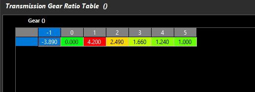
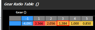
NOTE: The Gear Ratio Table MUST be completed for this function to operate correctly. See Vehicle Functions -> Vehicle Dynamics menu.
Once DBW has returned to within 5% of the Target this timeout gets applied. When Time = 0 the Rev-match limit is then removed.
ONLY applies to DBW applications.
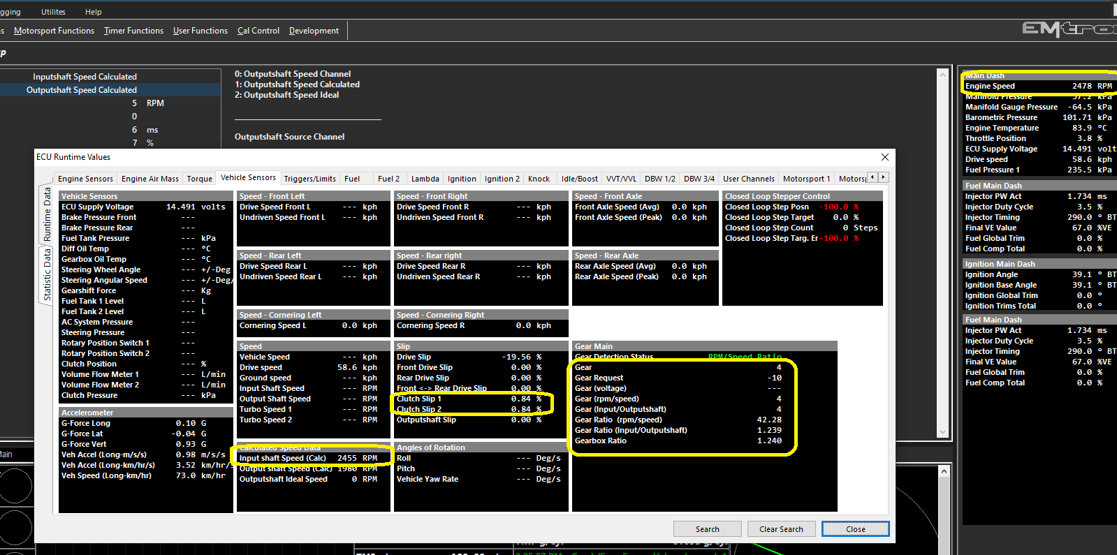
Downshift Next Gear Timeout
The Next Gear MUST be reached within this time for the Downshift to be valid. If this does not occur the ECU will re-try the gear shift by the number of times set in the Upshift “Downshift Re-retry Count” Setting.
Time starts when Downshift Solenoid is switched ON.
Typical Value = 100ms
Downshift Re-Try Count
The number of time the ECU will re-attempt a failed Gear Shift.
ONLY Applies when Electronic(Paddle) mode selected
Typical Value = 3
Downshift Stacking Limit
Sets the maximum number of Upshift Requests that can be stacked.
0 =OFF
Downshift Min Engine Speed
The Engine Speed MUST be less than this value for the Downshift request to be valid
0 = OFF
Downshift Min Throttle
The Throttle Position MUST be less than this value for the Downshift request to be valid
0 = OFF
Downshift Max Pedal
The Pedal Position 1 max position for Dowshift request to be valid
0 = OFF
Downshift User Enable
The User Channel when selected must be ON
for the Downshift request to be valid.
0: OFF
1: User Channel 1
2: User Channel 2
3: User Channel 3
4: User Channel 4
5: User Channel 5
6: User Channel 6
7: User Channel 7
8: User Channel 8
9: User Channel 9
10: User Channel 10
Downshift Force Hysteresis
Prevents Gearshift re-triggering.
Example:
Gear Force Positive = 8kg
Downshift Force Hysteresis = 60%
Downshift will be triggered when Gear Force > 8kg.
Once complete the Gear force will not be allowed to trigger the Gearshift until it falls below 60% of 8kg ..ie Force MUST be less than 3.2Kg (8- 4.8)
Downshift Solenoid Delay
Downshift Solenoid Delay
This is the length of time from the initial Downshift Request to when the Downshift Solenoid is switched ON.
Resolution = 1ms
Downshift Throttle Duration
Downshift Throttle Duration
Sets the Duration of the DBW throttle position change when Force is used
Sets the Timeout of the DBW throttle position change when Paddle shift is used
** This position will override other torque management functions regarding throttle control
Gear Cut End Source
Gear Cut End Source
This setting controls the way the cut is to be ended once triggered. The following settings are available :
0: Timed Setting uses the Cut Time Table to
control the Cut length
1: “Clutch Switch” Status changing to OFF ends
the Cut
2: “Gear Cut Switch” Status changing to OFF ends
the Cut
3: If Positive Force Started the cut, the cut End
will occur when the Force is less than the
Postive Force Threshold - Gear Cut Force Hysteresis.
The inverse applies for a Negative Force Start Cut
Example:
Force Threshold = 8.0kg

Gear Cut Force Hysteresis = 3.0kg

Start Cut at > 8.0 kg

End Cut at < 5.0 kg

Force Threshold = -6.0kg

Gear Cut Force Hysteresis = 3.0kg

Start Cut at > -6.0 kg

End Cut at < -3.0 kg
NOTE: “Gear Cut Start Source” MUST be
selected as 2 (Gear Shift Force) for this setting
to work
4: Next Gear Stable will determine the cut time. Once
the next gear is confirmed the ECU will initiate a cut end
Gear Cut Ign Retard Mode
Gear Cut Ign Retard Mode
Applies the Ignition Retard as either an
Offset or Percentage of Current Ign Angle
Example: Current Ignition Angle = 20.0 BTDC
Offset = 15.0 Deg Retard.
Ignition Angle during Gear Cut is
= 20.0 - 15.0 = 5.0 Deg BTDC
Percentage = 50.0 % Retard.
Ignition Angle During Cut :
= 20 - 50% x 20.0 = 10.0 Deg BTDC
0: Offset
1: Percentage
Cut Level Recovery Time Table
Cut Level Recovery Time Table
The total time that the cut will be phased back to 0.
Gear Cut Start Source
Gear Cut Start Source
This is the source ECU uses to trigger the cut for gear shift. There are three methods that can be selected :
0: Digitial Input set to Clutch Switch
This setting will allow the system to trigger by “Clutch.Switch” input.
1: Digitial Input set to Gear Cut Switch
This setting will allow the system to trigger by “Gear Cut Switch” Input. Commonly this signal is supplied by a gear shifter mounted switch
2: Gear Shift Force
This setting will allow the system to trigger by “Gear Shift Force” Input. Commonly this signal is supplied a gear shift mounted amplified strain gauge output. This is generally the best method for triggering but does require hardware which can provide the ECU a voltage output based on the force.
Cut Level Table
Cut Level Table
This is the engine cut % applied when gear cut it active
Cut Time Table
Cut Time Table
This table sets the cut time if the “Gear Cut End Source” is set
to “Timed”
Cut Timeout Table
Cut Timeout Table
Time in seconds that the cut time will be clamped to. No matter what
setting is configured the total cut time will be limited by the ECU to
this time.
Gear Detection Setup
Gear Detection Setup
Gear Position Enable
Enables the Gear Detection
0 = OFF
1 = ON
Gear Position Calculation
Choose the method of Gear Position Calculation
Various modes are available.
0 = Gear Position Voltage 1 - Input must be assigned and calibrated
1 = RPM/Speed Ratio - Gear is derived by RPM/speed channel defined (Under Gear Position RPM/Speed Setup)
2 = CAN Bus - Gear is received over CAN bus
3 = Inputshaft/Outputshaft Ratio - Gear is derived by calculating ratio of inputshaft/outputshaft speed
4= Gear Position Voltage 2 - Input must be assigned and calibrated
Proper gear detection and channel calculation such as Input shaft Speed (Calc) are important for functions in the ECU such as Motorsport Gearshift control (regarding rev matching control), some Application Build systems (CAN Integration), and other general functions in the ECU that may be being used.
Input/Outputshaft Speed Calculations
Inputshaft speed Calculated can be derived from looking at Outputshaft Speed Channels -> Vehicle Dynamics -> Inputshaft Speed Calculated
“1” Output Shaft Speed Calculated is derive from selecting a calibrated speed channel. -> Vehicle Functions -> Vehicle Dynamics -> Outputshaft Speed Calculated
** The ECU generates this channel by deriving the speed through the wheel circumference and final drive under Vehicle Dynamics -> Vehicle Main Setup ->
The Inputshaft speed is calculated furthermore through the Transmission Ratio Table. Vehicle Dynamics -> Transmission Gear Ratio Table ->
Validating Inputshaft speed (Calc) channel
To validate Inputshaft speed (Calc), logging engine speed vs Inputshaft Speed (Calc) can be plotted ->
Also by looking at runtimes for channel comparisons can be done ->
** Note Gear Ratio (Input/Outputshaft) (calculated from Input shaft speed (Calc) vs Output shaft Speed (Calc) vs Gearbox Ratio (Transmission Ratio tabe) is the same
** Note Clutch Slip Channels are near 0% (calculated % difference between Engine Speed and Clutch Slip Source Channel)
(define clutch slip in Tuning -> Vehicle Functions -> Vehicle Dynamics -> Clutch Slip = Currently Set to Inputshaft Speed Calculated)
** If there is error in Input shaft Speed (Calc) vs Engine Speed (therefore there will be error in Gear Ratio (Input/Outputshaft) and Clutch Slip), then settings/calibration needs attention in regards to speed sensor calibration, wheel diameter, final drive, or transmission ratios
Gear Force Negative
Gear Force Negative
This is the negative force required to trigger a cut event if
this “Gear Cut Start Source” is configured to “Gear Shift Force”
Gear Force Positive
Gear Force Positive
This is the positive force required to trigger a cut event if
this “Gear Cut Start Source” is configured to “Gear Shift Force”
Fault Mode Cut Time
Fault Mode Cut Time
Gearshift Mode:
This table sets the open loop cut time when the system is in fault mode.
(For example Gear Position sensor has failed or Gear Position Tracking Error)
Gearcut Mode:
This table sets the cut time if the “Gear Cut End Source” is set to “Timed”
Gear Shift Control
Gearshift Control Function Setup
Emtron has multiple methods of Gearshift Control
Config, Function Setup, Motorsport, Gearshift Control
Mechanical - Manual Shift (Force)
Electronic - Paddle
There are also other CAN BUS Triggered modes for Application Build versions.
** See those Application Build Manuals for details
Configure Gear Position using the “Gear Detection Voltage” channel . This is normally a barrel position sensor located on the sequential gearbox. See Config View -> Inputs -> Vehicle Tab
Configure the Inputs. Configure the following from the Inputs -> Motorsport tab:
Paddle Shift mode
Upshift Paddle Input
Downshift Paddle Input
Reverse Lockout Switch if required
Compressor Pressure Input if required
In Force Shift mode
Gearshift Force Input
For Paddle Shift to function correctly and safely at least least two(2) gear channel needs to be tracked for redundancy purposes. Commonly a Gear Detection voltage will be reported from a gear drum mounted to the transmission along with a speed sensor which may be used by the ECU to calculate the gear along with generating Engine Speed requests fro rev-matching limiters. The vehicles wheel diameter and final drive ratio should be confirmed correct. Then enter the correct transmission gear ratios into the table :
See Vehicle Dynamics->Vehicle Main The gear ratio table needs to be accurately set for this to occur.
. See Tuning view -> Vehicle Functions -> Vehicle Dynamics menu -> Transmission Gear Ratio table. Use -1 for Reverse.
Gear-Shift-Down-Shift-Flow
Gear-Shift-Up-Shift-Flow
Gearshift Compressor Setup
Gearshift Compressor Setup
Gearshift Comp Pressure Target
Pressure Target for Compressor. The Output will be switch off when the pressure is reached.\
Gearshift Comp Pressure Hysteresis
This value is subtracted from the Pressure Target and determines when the Output will be switched back ON.
Pressure Target = 150.0 PSI
Pressure Hysteresis = 10.0 PSI
The Pump will stay ON until 150.0 PSI is reached. The Pump will then turn OFF. When the pressure drops to 140 PSI to pump will switch back ON\
Gearshift Comp Voltage Lockout
The Gearshift Compressor Output will be switched OFF below this Voltage. Used normally to switch OFF the Compressor to prevent battery drain in Low Voltage situations.
0 = OFF\
Gearshift Comp RPM Lockout
The Gearshift Compressor Output will be switched OFF below this Engine Speed. Used normally to switch OFF the Pump during low RPM and cranking.
0 = OFF
Typical Value = 400 RPM
Gearshift User Lockout
The Gearshift Compressor Output will be switched OFF when the User Channel is ON/Active.
0: OFF
1: User Channel 1
2: User Channel 2
3: User Channel 3
4: User Channel 4
5: User Channel 5
6: User Channel 6
7: User Channel 7
8: User Channel 8
9: User Channel 9
10: User Channel 10
Gearshift Comp Timeout
With the Compressor ON, if the Target pressure cannot be reached within this timeout value the Output will be switched OFF. The timer will only be reset when the Lockouts become active OR the Re-try Interval is reached/used.
0 = OFF
Typical Value = 30secs
Gearshift Comp Re-try Interval
In the event the Timeout is reach and the output is switched OFF the system will switch the ouput back ON at this interval in an attempt to keep system pressure. This event normally occurs when the feedback input fails.
0 = OFF
Gearshift Compressor Status
0    Disabled

1    OFF

2    ON

3    OFF - RPM Lockout

4    OFF - User Lockout

5    OFF - Timeout

6    OFF - I/P not selected

7    OFF -  Input in Fault

8    OFF - Voltage Lockout
Gearshift Control Status
0    Disabled

1    OK

2    X Gear I/P Fault - Open Loop

3    X Gear Position Setup Err

4    X Gear Request Setup Err

5    X Gear Voltage Input OFF

6    X Gear Cut Func ON

7    X Rev-match set Gear Ratios

8    X Missing UpShift Output

9    X Missing DownShift Output

10    X Missing UpShift Input

11    X Missing DownShift Input

12    X Missing Force Input

13    X Timeout Setting LOW
Gearshift Control Tuning
Gearshift Control Tuning
The first step in the tuning section of the function is to setup the gear request input method.
The target compressor pressure represented in kpa. The transmission manufacturer should be able to advise on the maximum pressure to operate with however common settings are between 600-800kpa.
Gearshift Comp Pressure Hysteresis
The amount the compressor pressure needs to drop below the target before the compressor is switched back on. Ideally the supply pressure should be kept as constant as possible for consistent shift performance.
Gearshift Comp Voltage Lockout
Minimum ECU supply voltage to allow the compressor to operate.
Gearshift Comp RPM Lockout
Minimum Engine Speed to allow the compressor to operate. This is usually set to reduce battery load while the vehicle supply is powered.
Gearshift Comp User Lockout
A user channel may be used to lockout the compressor if the default lockouts are not satisfactory for the application.
Gearshift Comp Timeout
If the compressor target is not reached within this time the ECU will assume there must be a fault in the system. Most common faults would be a leak or faulty compressor motor.
Gearshift Comp Re-Try Interval
Once the compressor pressure target is not reached within the time out the ECU will wait for the re-try interval and attempt to turn on the compressor again.
Upshift Setup
Tuning View -> Motorsport Functions -> Gearshift Control -> Upshift Control -> Upshift Setup
Upshuft Cut Type
This sets the type of cutting used for gearshift control.
Fuel Cut Only
This system will cause a slower recovery of the engine from the cut leading to longer overall effective shift times. The will lead to quieter operation on the gearshift due to lack of unburnt fuel in the exhaust to ignite.
Ignition Cut Only
This system will cause very fast recovery as the fuel film does not require rebuilding after the shift recover. Depending on the tuning strategy and hardware careful consideration needs to be taken when choosing this cutting method. Unburnt fuel igniting in the exhaust can lead turbocharger and exhaust damage. Valve train needs to be considered also when choosing this system.
Fuel + Ign Cut
This system employs a combination of both fuel and ignition cutting strategies. This system is generally the most favored method as there is a lot of flexibility with the cut strategy balance.
Upshift Throttle Override
The ECU can override the DBW throttle position during and Upshft event. Generally for the fastest shifting performance cutting and retard strategies alone will allow will achieve the best results. During low traction surface shifting is can be possible to help unload the dog by closing the throttle during the shift.
Upshift Rev-matching Limit
This setting toggles the rev matching feature. The ECU can perform a user level cut strategy which then leads into the Engine Speed Limit rev-matching strategy. It is advised to always have this feature enabled for best performance.
Upper Rev-match Control Range (+/-)
This is the range the Engine speed limit controls the cut %. For upshift this should be a positive(+ve) number. 400rpm is a good starting range. Once the engine is within 400rpm of the ECU calculated rev-match target cut will commence.
Upshift Re-Try Count
The ECU employs a strategy of retrying the shift if it is deemed to have either failed or will fail based on a the in coming sensor data.
Upshift Next Gear Timeout
This is the timeout allowed for the upshift event to occur in total. All cutting and instructions should have completed within this time. If the gear has failed to achieve a shift and upshift counter will increment. All retries would have occurred within this timeout.
Upshift Stacking Limit
The ECU has the ability to increment a shift request counter for the purpose of “stacking” shifts. This number limits the amount of shifts that can be stacked. When the conditions are satisfied a shift will occur and the stack count will decrement until the count reaches zero.
Upshift Min Engine Speed
Upshift Min Throttle
Upshft Min Pedal
Upshift User Enable
Downshift Setup
Rev-matching describes the process of matching engine speed to the gear you are shifting into/requested gear. With Downshifting the Engine Speed must be increased so additional air needs to be introduced with the ECU supporting a variety of methods. This reduces stress on the drive-line.
The Downshift setting can be found in the Tuning View -> Motorsport Functions -> Gearshift Control -> Downshift Control menu.
Downshift Cut Type
This setting is used in 1) The Pre-Cut Downshift function which allows the “dog” to be unloaded 2) For Rev-Matching
Downshift Throttle Override
Allows additional air to be introduced into the engine on downshift. There are 5 options:
4: Throttle Solenoid - Function Controlled (Non DBW application)
The “Duration Table” is an open loop control. A table is used to enter in the length of time the Downshift Throttle Override will be active
“Function Controlled” allows the ECU to dynamically change the Throttle Override time based on the functions state. For example as the Gearshift “Next-Gear Stable” time varies, the ECU dynamically adjusts the Throttle Override time to match.
NOTE: You can use this function with the Rev-matching OFF. However, there is nothing limiting the engine speed so caution should be used when setting the amount of additional air introduced into the engine.
Downshift Rev-matching Limit
The Downshift Rev-matching Limit function will Limit the engine RPM to match the requested downshift gear. The ECU uses the transmission gear ratios between the current gear and requested gear to calculate a Rev-matched RPM Limit Target.
Make sure the Downshift Rev-Match RPM Target Correction table is setup correctly. Initialise to 0% for first time setups.
Additional air MUST also be introduced into the engine, either by using the DBW or a solenoid to manual open a cable throttle. The ECU will control this with options available in the Downshift Throttle Override setting.
Downshift Rev-Match Cut Control Range
Controls the RPM Range over which the engine will be cut when the Downshift limit is active. The Min Cut and Max Cuts are locked respectively at 0% and 95%
Example:
Rev-match RPM Target = 4000
Min Cut = 0%
Max Cut = 95%
Range = +400 0RPM,
Engine Speed: 4000 RPM = 0% Cu
Engine Speed: 4400 RPM = 95% Cut
Range = -400 RPM (Recommended)
Engine Speed: 4000 RPM = 95% Cut
Engine Speed: 3400 RPM = 0% Cut
Downshift Rev-Match End Timeout
The Rev-match Limit will be removed once the DBW has returned to within 5% of its normal position. This Timeout allows additional time for the system to stabilize before the limit is removed. If this setting is required typical times range from 10 - 50ms.
NOTE: This setting ONLY applies to DBW applications. If not used set to zero.
Downshift Rev-Match RPM Target Correction Table
Applies a percentage correction to the calculated Rev-Match Target. The range is +/- 100%.
Example:
Rev-match RPM Target = 4000
Driver Torque Demand = 25Nm
Based on the below table the %Correction is 5%.
Final Rev-match RPM Target = 4000 x 1.05 = 4200 RPM
Downshift DBW Override Position Table
Sets the Servo Position target that the DBW will move to during the downshift. This is an absolute position. The below table shows a typical 4 cylinder engine example.
Downshift DBW/Throttle Override Duration Table
The length of time the air override system is introducing additional air during the downshift. This can be a Solenoid pushing on a cable throttle or DBW. This table is only enabled when the Downshift Throttle Override setting is non-function controlled i.e. Open Loop Duration Table as shown below.
Final Example
In 4th gear, downshifting to 3rd:
Downshift Rev-Match Control Range = -400 RPM
Current rpm = 6000
Gear ratio 4th = 1.000
Gear ratio 3rd = 1.230
Downshift Rev-Match RPM Target Correction = 2%
Target Downshift RPM = 6000 x 1.230/1.000
Target Downshift RPM = 7380
Apply 2% Target Correction:
Target Downshift RPM = 7380 x 1.02
Target Downshift RPM = 7527
Downshift RPM High: 7527 RPM at 95% Cut
Downshift RPM Low: 7127 RPM at 0% Cut
So the ECU will Limit the Engine Speed between 7127 and 7527 assuming sufficient air has been introduced
Gearshift Downshift Status
0    Disabled

1    Ready ...

2    ON

3    OFF - Max TPS

4    OFF - Max RPM

5    OFF - User

6    OFF - Enable Table

7    OFF - Max PPS

8    OFF - Gearshift Status

9    OFF - SPARE

10    Rev: Dnshift Sw Timer

11    R: Upshift Sw Waiting ..

12    R: Reverse Sw Waiting ..

13    R: Clutch Switch

14    R: Clutch Position

15    R: User Lockout

16    R: Speed Lockout

17    R: RPM Lockout
Gearshift - Paddle
Gearshift without “shift position” – Tolerance Voltage
Larger tolerance voltage number will achieve next gear stable sooner. Consider volt change per gear, to determine tolerance volt.
Gear volt spread is 0.60x volt. 0.225 tolerance will achieve “gear change” 63% of the way through the barrel turn.
This is a way control the shift timing if using “Next Gear Stable” function
Above example is vehicle using a static cut value (75%).
Next Gear % Cut Level and Ignition Retard Recovery Time are being leveraged to phase back in engine power.
Pre-loading Gearbox
Necessary to achieve swift ratchet action, similar to a “stick” setup where you’d deny cut until a specific force on the shifter.
Mechanical lag of linakge, air lines, etc – all contribute to needing pre-loading.
Cars with high forward momentum will need pre-loading to ensure the middle phase of the gearshift happens at the right time, when the dogs are fully dis-engaged.
Observe engine in full cut off, engine speed decelerating, but speed still increasing. The barrel has not turned at the right time (when the engine speed decelerated) and caught the previous gear deceleration side of the dog hanging the upshift up.
Pre-loading can be done with Torque Reduction Delay table, or if Shift Position is available, in full closed loop ->
Torque Reduction and Re-Introduction
Reduction in torque can be achieved many ways with fuel, ignition, or both cut tables. Retard tables. Rev matching cut functions, and even DBW target hijacking.
Different scenarios will call for different methods of reduction types.
On turbocharged engines, using too much cut may reduce exhaust energy affecting turbine speed.
Too much retard may increase exhaust energy
A global boost control comp for “Ignition Trims Total” is suggested
Re-Introduction of torque is critical to prevent drivetrain from clashing, bouncing on dogs (drive/decel), and creating excessive ringing in the driveline.
Plotting/observing Engine Torque (requires tuned torque model) runtimes can help what the engine is doing during the shift quickly
Using Shift Position channels in cut tables
Cut Recovery Time table functions off values in the cut table – if last value is “0” then recovery time has nothing to recover from
Tolerance Voltage in the Gear Volt input setup should be considered. Suggest using a lower tolerance voltage to control the ECU through the shift
Gearshift Setup
Gear Position Order
0: N123456
1: RN123456
2: 1N23456
This settings allows the ECU can determine the correct shift and half-shift sequence
Option 1: RN123456.
In some transmissions neutral is located half-way between R and 1st. To allow Neutral to be selected, the “Half-Shift” setting should be enabled.
NOTES:
** 1st -> Neutral will require a Half-Shift. (Downshift Solenoid will be modulated)
** Reverse -> Neutral will require a Half-Shift (Upshift Solenoid will be modulated)
** Neutral to reverse Half-Shift is not required as reverse gear is located at the end of the shift drum.
Option 2: 1N23456
In this configuration neutral is located half-way between 1st and 2nd. To allow Neutral to be selected, the “1st -> N Half-Shift” setting should be enabled.
NOTES:
** 1st -> Neutral will require a Half-Shift (Upshift Solenoid will be modulated)
** N -> 1st upshift request, the ECU will activate the downshift solenoid
** Neutral to 1st Half-Shift is not required as 1st gear is located at the end of the shift drum.
Gear Position Tracking
0: OFF
1: RPM/Speed Ratio
2: Gear Detection Voltage 2
3: InputShaft /Output Shaft Speed Ratio
Gearshift tracking feature helps reduce transmission damage by cross referencing two independent Gear positions at the start of a gearshift. The ECU uses the Main and Tracking Gear Positions to achieve this.
It is HIGHLY recommended to use this feature.
Main/Primary Gear Position: The Gear Position Voltage 1 Input channel is used.
Tracking Gear Position: This is selectable under this setting.
When the Main and Tracking Gear positions don’t match the actual Gear Position cannot be determined with absolute certainty. This can be caused by a sensor entering a Fault condition or an absolute tracking error.
To prevent transmission damage the following precautions are used:
The ECU requires the clutch to be depressed before a shift can occur. The ECU checks this condition by looking at the Clutch Switch Status or Clutch Pressure. The ECU will NOT upshift or downshift until the clutch is depressed.
The Gearshift runs in open-loop mode. The gearshift time is calculated from the “Fault Mode Cut Time” table and does not use the “next gear stable” strategy.
Rev-matching is disabled.
In the event the Main Gear position enters a Fault condition, the Tracking Gear position will be loaded as the main Gear Position.
NOTE: Gear Position Gear Tracking is always locked out in the following gears : R, N, 1st
Gear Tracking Clutch Pressure Threshold
When a Gear Position tracking error occurs the clutch pressure MUST exceed this setting before the ECU will allow a downshift or upshift.
NOTE: Clutch Pressure or Clutch Switch can be used but MUST be configured.
1st -> N Half-Shift Enable
0: OFF
1: ON
Neutral Gear Ordering RN12345 - Neutral placed half-way between R and 1st.
This setting allows the ECU to “Half-Shift” when selecting 1st -> Neutral. It does this by appling a PWM signal to the downshift solenoid with a user adjustable duty cycle and ramp rate
Neutral Gear Ordering 1N2345 - Neutral placed half-way between 1st and 2nd.
This setting allows the ECU to “Half-Shift” when selecting 1st -> Neutral. It does this by appling a PWM signal to the upshift solenoid with a user adjustable duty cycle and ramp rate
1st -> N Half-Shift Start Duty Cycle
Start Duty Cycle in Half Shift Mode applied to the gear solenoid. The solenoid used will depend on the Gear Position Order.
NOTE: The “Next Gear Timeout” can be overwritten in Half-Shift Mode by holding the Downshift Paddle. For a maximum of 2 seconds the Half-Shift mode will operate until the paddle is released. The Half-shift mode will switch OFF when next stable is reached overriding any paddle input.
Freq fixed at 20Hz
Typical Value = 50 %DC
Resolution 2.0%
1st -> N Half-Shift Ramp Rate
The Duty Cycle will be increased by this amount per cycle.
Typical Value = 4 %DC
Resolution 2.0%
Example:
Half-Shift Start Duty Cycle = 50.0%
Half-Shift Ramp Rate = 6.0%
1st PWM Pulse = 50% DC
2nd PWM Pulse =56% DC
3rd PWM Pulse = 62% DC
The PWM will be switched OFF when the next gear has been detected or when the paddle is released.
Maximum Time limited to 2 seconds.
1st -> N Half-Shift Max Duty Cycle
Maximum duty cycle allowed on the solenoid during Half-Shift operation.
Resolution 2.0%
1st -> N Half-Shift Duty Cycle - Opposite
Fixed Duty Cycle to be used on the opposing gearshift solenoid. This can be used as a “brake” and help prevent over rotation of the shift drum. This PWM runs in-phase with the “1st -> N: Half-Shift Start Duty Cycle” PWM signal.
0 = OFF
Typical Value = 10 %DC
Resolution 2.0%
Rev -> N Half-Shift Enable
0: OFF
1: ON
Neutral Gear Ordering RN12345 - Neutral placed half-way between R and 1st.
This setting allows the ECU to “Half-Shift” when selecting Reverse -> Neutral. It does this by appling a 20Hz PWM signal to the upshift solenoid with a user adjustable duty cycle and ramp rate.
Rev -> N Half-Shift Start Duty Cycle
Start Duty Cycle in Half Shift Mode applied to the gear solenoid. The solenoid used will depend on the Gear Position Order.
NOTE: The “Next Gear Timeout” can be overwritten in Half-Shift Mode by holding the Downshift Paddle. For a maximum of 2 seconds the Half-Shift mode will operate until the paddle is released. The Half-shift mode will switch OFF when next stable is reached overriding any paddle input.
Freq fixed at 20Hz
Typical Value = 50 %DC
Resolution 2.0%
Rev -> N Half-Shift Ramp Rate
The Duty Cycle will be increased by this amount per cycle.
Typical Value = 4 %DC
Resolution 2.0%
Example:
Half-Shift Start Duty Cycle = 50.0%
Half-Shift Ramp Rate = 6.0%
1st PWM Pulse = 50% DC
2nd PWM Pulse =56% DC
3rd PWM Pulse = 62% DC
The PWM will be switched OFF when the next gear has been detected or when the paddle is released.
Maximum Time limited to 2 seconds.
Rev -> N Half-Shift Max Duty Cycle
Maximum duty cycle allowed on the solenoid during Half-Shift operation.
Resolution 2.0%
Rev -> N Half-Shift Duty Cycle - Opposite
Fixed Duty Cycle to be used on the opposing gearshift solenoid. This can be used as a “brake” and help prevent over rotation of the shift drum. This PWM runs in-phase with the “Rev -> N: Half-Shift Start Duty Cycle” PWM signal.
0 = OFF
Typical Value = 10 %DC
Resolution 2.0%
Gearshift Upshift Status
0    Disabled

1    Ready ...

2    ON

3    OFF - Min TPS

4    OFF - Min RPM

5    OFF - User

6    OFF - Enable Table

7    OFF - Min PPS

8    OFF - Gearshift Status
Upshift DBW Position
Upshift DBW Position
Sets the throttle position target that the DBW throttle will move to during the up shift.
This is an absolute position of the DBW Servo.
** This position will override other torque management functions regarding throttle control
Upshift Next Gear Solenoid Hold Time
Upshift Next Gear Solenoid Hold Time
This is the time the Solenoid stays ON once next gear stable has been achieved .
Resolution = 1ms
Upshift Next Gear Torque Recovery Delay
Upshift Next Gear Torque Recovery Delay
Rev-Match OFF
This is the time the Engine Cut/Ignition Retard stays active once Next Gear Stable has been achieved.
Rev-Match ON
This is the time the Rev-match cut and Ignition Retatd remains active once Next Gear Stable has been achieved.
Resolution = 1ms
Upshift Request Enable Table
Upshift Request Enable Table
The Table output must be Enabled allowing the UpShift request to be valid.
(set to 100 if not required)
0 = Shift Request Disabled
100 = Shift Request Enabled
50 = No Change
Upshift Rev-Match Enable Table
Upshift Rev-Match Enable Table
This table controls when the Rev-Match function is started.
0 = OFF
100 = ON
Any other value = no change
It is important the Rev-match RPM limiting starts AFTER the initial Torque Reduction Cut/Retard. This is because the Upshift Rev-Match RPM limit will be lower than the current Engine Speed and will most likely take %cut priority, preventing the initial Torque Reduction Cut/Retard from working as expected.
Upshift Rev-Match RPM Target Correction
Upshift Rev-Match RPM Target Correction
This table controls adjusts the Rev-Match RPM Target +/- in units of %.
Use this to raise or lower the Rev-Match RPM Target
Upshift Setup
Upshift Debounce Time
The Upshift Paddle must be held for this time for the request to be valid.
This setting prevents accidental requests in harsh Motorsport environments (vibration and vehicle harmonics).
Upshift Torque Reduction Type
0: Fuel Cut Only
1: Ign Cut Only
2: Fuel + Ign Cut
\
Upshift Ign Retard Mode
0: OFF
1: Offset
2: Percentage
Applies the Ignition Retard as either an Offset or Percentage of Current Ign Angle
Ignition Angle During Cut := 20 - 50% x 20.0 = 10.0 Deg BTDC
Upshift Torque Reduction Min Time
The Upshift function works by initially applying Torque Reduction, before then entering the Rev-Matching phase controlled by the Rev-Match Enable Table.
This setting ensures the Torque Reduction is ALWAYS active at the start of the gearshift for the time entered before the Rev-Matching can occur.
Typcial value : 10 -20ms
Upshift Throttle Override
0: OFF
1: DBW 1 - Duration Table
2: DBW 1 - Function Controlled
This setting overrides the throttle on upshift .
Duration Table is Open Loop mode and used to control the length of time the DBW is controlled.
Function Controlled is Closed Loop so the Gearshift Function is used to control the length of time the DBW is controlled.
The goal is to reduce the airflow into the engine to match the engine speed of the requested upshift gear.
NOTE: The Rev-matching Limit setting can also be switched ON, which limits the engine the to correct rpm.
Upshift Rev-Matching Limit
Upshift Rev-matching Limit
Rev-matching Upshift Function will Limit the engine RPM to match the requested Upshift gear. The ECU uses Output shaft RPM and Transmission ratios between the current gear and requested gear to calculate a Rev-matched RPM Target.
i.e. Matching Transmission Input and Output speed referenced by Gear Ratio
NOTE 1: Output Shaft must be configured. This means Wheel Diameter and Final Drive ratios must be set correctly.
NOTE 2: The Gear Ratio Table MUST be completed for this function to operate correctly. See Vehicle Functions -> Vehicle Dynamics menu.
NOTE 3: It is important the Rev-match RPM limiting starts AFTER the initial Torque Reduction Cut/Retard. This is because the Upshift Rev-Match RPM limit will be lower than the current Engine Speed and will most likely take %cut priority, preventing the initial Torque Reduction Cut/Retard from working.
NOTE 4: Make sure the “Upshift Rev-Match RPM Target Correction” table is setup/initialised correctly
The Next Gear MUST be reached within this time forthe Upshift to be valid. If this does not occur the ECU willre-try the gear shift by the number of time set in the Upshift “Upshift Re-retry Count” Setting.
Time starts when Upshift Solenoid is switched ON.
Typical Value = 100ms
Upshift Re-Try Count
The number of time the ECU will re-attempt a failed Gear Shift.
ONLY Applies when Electronic(Paddle) mode selected
Typical Value = 3
Upshift Stacking Limit
Sets the maximum number of Upshift Requests
that can be stacked.
0 =OFF
Upshift Min Engine Speed
The Engine Speed MUST be greater than this
value for the UpShift request to be valid
0 = OFF
Upshift Min Throttle
The Throttle Position MUST be greater than
this value for the UpShift request to be valid
0 = OFF
Upshift Min Pedal
The Pedal Position 1 MUST be greater than
this value for the UpShift request to be valid
0 = OFF
Upshift User Enable
The User Channel when selected must be ON
for the UpShift request to be valid.
0: OFF
1: User Channel 1
2: User Channel 2
3: User Channel 3
4: User Channel 4
5: User Channel 5
6: User Channel 6
7: User Channel 7
8: User Channel 8
9: User Channel 9
10: User Channel 10
Upshift Force Hysteresis
Prevents Gearshift re-triggering.
Example:
Gear Force Positive = 8kg
Upshift Force Hysteresis = 60%
Upshift will be triggered when Gear Force > 8kg.
Once complete the Gear force will not be allowed to trigger the Gearshift until it falls below 60% of 8kg ..ie Force MUST be less than 3.2Kg (8- 4.8)
Upshift Throttle Duration
Upshift Throttle Duration
Sets the Duration of the DBW throttle position change when Force is used
Sets the Timeout of the DBW throttle position change when Paddle shift is used
** This position will override other torque management functions regarding throttle control
Upshift Torque Reduction Delay
Upshift Torque Reduction Delay
This is the length of time from when :
Upshift solenoid is switch ON (Electronic) OR
Force Threshold is exceeded (Mechanical)
to when the Engine Torque Reduction begins with Engine %Cutting and Ignition Retard.
Resolution = 1ms
** For Electronic Paddle Shift, this is used to pre-load the shift
Upshift Torque Reduction Ign/Fuel %Cut Level
Upshift Torque Reduction Ign/Fuel %Cut Level
This is the %cut applied when gear cut it active
Upshift Torque Reduction Ignition Retard
Upshift Torque Ignition Retard
This is the amount of Ignition Retard applied during the entire Upshift event
Allows the user to set the minimum and maximum deviation that can be used by the closed loop system.
These parameters can be expanded into a 3D look up tables to provide greater accuracy regarding closed loop control.
** These values are Duty Cycle when using a solenoid, Step counts if using a stepper motor, or Position if using DBW.
Idle Closed Loop Control
Idle Closed Loop Control
** For DBW, it is advised to use a PI control strategy (put D-Gain at zero). Also keep Idle PI Gains small.
See Plugin Sample Files for examples on these settings.
** For DBW, it is advised to use TMF mode for better closed loop control (see Idle Speed Tuning)
** If Idle Ignition Control is also ON, make sure the Idle Ignition I-Gain is set to zero so both Idle Ignition and Idle DBW systems are not fighting each other
Example : Do not have I-Gain active on both systems.
Idle PID Setup
Control Rate
The rate at which the PID control algorithm calculations are performed.
Typical : 10 Hz
Idle Deadband +/-
The output control signal is held constant when the Input Signal (RPM) falls within the deadband range of the Setpoint (Idle Target). This helps reduce steady state error and oscillations.
Typical : 20 RPM
RPM Filter
Filters the RPM signal to allow better PID control
Typical : 5
Integral Positive/Negative Clamp
Allows the user to set the minimum and maximum I gain compensation used by the closed loop system.
Re-entry Delay
Delay once all lockouts are cleared before Closed Loop Idle Control becomes active.
** Will immediately become active if engine speed falls below the Target RPM
Idle Speed Control Configuration (TMF)
This section assumes the DBW has been configured and operating correctly.
The following steps should be used to configure the Idle Speed control system to work using Throttle Mass Flow.
Configure the Throttle Mass Flow Idle Speed Control output function type using the menu:
Config -> Functions -> Function Output Setup -> Engine Functions Tab -> Idle Speed Control
Select either DBW 1 TMF or DBW 1 + 2 TMF
Configure the throttle body model using the menu: Tuning -> Engine Function -> Throttle Body Model -> Throttle Body Setup
Configure the Throttle Mass Flow model using the menu: Tuning -> Engine Function -> Throttle Body Model -> Throttle Mass Flow Setup
Step 1- Select the throttle mass flow enable type that is applicable to your configuration. Example: ON x 1 DBW Throttle Body
TMF idle valve option is for TMF fuel model on cable throttle engines & is not applicable to DBW TMF idle speed control.
The TMF idle valve size input is also only applicable to cable throttle TMF applications
Step 2 - Set Throttle 1 before plate pressure source
If you intend to use TMF in areas other than idle, there should be a pressure sensor already fitted before the throttle plate and this should be selected.
Example: Boost Pressure Sensor

In the case of only wanting to achieve TMF Idle Speed Control and there is no sensor fitted before the plate, simply select the internal       Barometric Pressure sensor.

Other more complicated methods are also available for advanced users..
Step 3. Set the Throttle 1 After Plate Pressure source. This is normally the MAP sensor
Step 4. Set the Throttle 1 Temperature source. This is normally set to charge temperature
Repeat for Throttle 2 if applicable
Throttle Body Area Table. See Throttle Body Setup help topic for more information
Confirm the Throttle Mass Flow calculations are operating, the data can be viewed from the Runtime menu (F3) -> Engine Data Calculated tab
Idle Speed Control Lockouts (TMF)
Idle speed control lockouts (TMF)
Tuning –> Engine Functions –> Idle Speed control –> Idle Speed Control lockouts (TMF)
TP1/PP1 Lockout
For TMF idle speed control, this is a Pedal Position 1 lockout target.
This feature uses a 0.5% hysteresis in its application.
Example: TP1/PP1 Lockout = 1.5%
PP1 < 1.5% Closed Loop becomes active
PP1 >= 2.0% Closed Loop goes into hold.
A typical value is 0.5% Pedal Position
Speed Channel
Used to define how the “Speed Lockout” is used.
0: OFF
1: Drive Speed
2: Ground Speed
3: Drive Speed Front L
4: Drive Speed Front R
5: Drive Speed Rear L
6: Drive Speed Rear R
7: Undriven Speed Front L
8: Undriven Speed Front R
9: Undriven Speed Rear L
10: Undriven Speed Rear R
11: Front Axle Speed
12: Rear Axle Speed
13: Vehicle Speed
**** Speed inputs must be defined and properly calibrated under “Input Setup”**
Speed Lockout
Locks out Idle Speed Control when the speed is greater than or equal to this value (KPH).
A typical value is 5.0
Note: A Speed Channel must be defined to function
Idle Target Tracking RPM Range
The engine speed must fall to the Idle Target + Idle Target Tracking RPM Range. This is the rpm threshold for TMF idle speed control activation.
Example:
Idle Target rpm (Plus any Offsets applied) = 800
Idle Target Tracking RPM Range = 350
TMF Idle Speed Control will become active when the engine speed falls to equal 1150 RPM.
A typical vale is 350 RPM
Idle Target Tracking Decay – Neutral
This function sets the rate of decay to idle in rpm per second that the engine speed reduction is applied once the engine speed is within the Idle Target Tracking RPM Range and the transmission is regarded to be in Neutral
A typical value is 250 rpm/sec
Idle Target Tracking Decay – In Gear
This function sets the rate of decay to idle in rpm per second that the engine speed reduction is applied once the engine speed is within the Idle Target Tracking RPM Range and the transmission is regarded to be in Gear
A typical value is 250 rpm/sec
Idle Speed Control Lockouts
Idle Speed Lockouts
TP1/PP1 Lockout
% below in which Idle Speed Control system becomes active.
Throttle Position 1 used on Solenoid and Stepper systems
Pedal Position 1 used on DBW systems
Speed Channel
Used to define how the “Speed Lockout” is used.
0: OFF
1: Drive Speed
2: Ground Speed
3: Drive Speed Front L
4: Drive Speed Front R
5: Drive Speed Rear L
6: Drive Speed Rear R
7: Undriven Speed Front L
8: Undriven Speed Front R
9: Undriven Speed Rear L
10: Undriven Speed Rear R
11: Front Axle Speed
12: Rear Axle Speed
13: Vehicle Speed
** Speed inputs must be defined and properly calibrated under “Input Setup”
Speed Lockout
Locks out Idle Speed Control when the speed is greater than or equal to this value (KPH).
Typical : 5.0
** Speed Channel must be defined.
Idle Range Lockout
The engine speed must fall below the Idle Target + Idle Range Lockout before Idle Speed Control becomes active.
Example:
Idle Target = 800 (set from Idle Speed Control menu)
Idle Range Lockout = 400.
Idle Speed Control will become active when the engine speed falls below 1200 RPM.
Typical: 400 RPM
Idle Speed Control Setup (TMF)
Idle speed control Setup (TMF)
Tuning –> Engine Functions –> Idle Speed control –> Idle Speed Control setup (TMF)
Control method
Used to select either Open or Closed Loop.
Open Loop mode is generally used to setup initial settings before using Closed Loop mode.
0: Open Loop
1: Closed Loop
** Closed Loop applies PID functions to Idle Feed Forward
** Idle Feed Forward is derived from Idle Initial Position + any comp tables
Start-up idle hold time:
How long the ECU is required to remain at the predetermined flare rpm on start up.
Please note: The Initial position table when in open loop mode is just that, the initial position in g/s of airflow that the engine will target. Once closed loop TMF idle control is activated, the Idle Speed Control – Initial Position Table (g/s) becomes the feed forward table for TMF closed loop idle. It is no longer an initial position, rather it is an expected value that feeds into the TMF idle speed PID control strategy. The values to be set in this table are arrived at when using the TMF Idle speed control in Open Loop control much as one would with Open & Closed Loop Boost control (See Idle Speed Control – Initial Position Table (g/s)
Start-up idle decay rate:
This function sets the rate of decay to idle in rpm per second that engine speed reduction is applied; from the start up offset target rpm (Flare) to the idle target rpm once the engine is running and the start-up idle hold time has expired (See above)
Throttle area demand (idle) clamp:
The throttle area clamp is a safety feature that prevents the DBW servo from exceeding a set throttle body area percentage at idle and prevents unintended values when calibrating the function.
This value is directly related to the values previously imputed into the Throttle body area table
A typical value is 10% - this refers to 10% throttle area, not DBW servo position or TPS
See Throttle body set up – throttle body area table
Min Throttle area blend pedal to idle:
This is the threshold below which the Pedal Throttle Area Demand starts to blend
Open Loop mode is generally used to setup initial settings before using Closed Loop mode.
0: Open Loop
1: Closed Loop
** Closed Loop applies PID functions to Idle Feed Forward
** Idle Feed Forward is derived from Idle Initial Position + any comp tables
Startup Idle Hold Time
Time delay before idle speed control is active after startup
Startup Idle Decay Rate
Decay rate (in RPM/sec) after Startup Idle Hold Time expires
Stepper Direction
Used to set polarity of the stepper motor.
0: Normal
1: Reversed
Stepper Position Full Reset
Used to reset the stepper motor to its fully closed position. When set to ON the ECU will command the stepper motor to move 200 steps. Once complete the motor is returned to its default position.
This setting should be used on first installation when the position of the stepper motor is unknown.
Can be switched back to OFF at any time without effecting stepper motor operation.
0: OFF
1: ON
Stepper Reset
When set to Key-On the ECU will command the stepper motor to move 200 steps fully closed at Key-On.
Once completed the motor is returned to its default position.
The Key-OFF option requires the ECU EFI Relay control on be connected and working correctly (recommended).
0: Key-ON
1: Key-OFF
Idle Speed Control
Idle Speed Control
The following calculated run times are generated by Emtron that are Ide Speed Control related (to be further discussed more specifically):
Idle Target         –     Current Target Idle Speed

Idle Position        -    Current Live Idle Position

Idle Target Error         -     Error from Target Idle Speed

Idle Position Base     -     Base Position of Idle Speed (%/Steps)

Idle Position Flow Target    -     Flow Target when using Idle TMF mode (g/second)

Throttle Area - Idle     –     Idle Throttle Area %

Pedal Position 1        –     Pedal Position

Idle Target Offsets (grp)    –     Offsets to Idle Target (RPM)

Idle Comps (group)     –     Offsets to Idle Position (%/Steps)

Idle Status         –     Current status of Idle Speed Control

Idle PID Status        -    Status of Idle Speed Control Closed Loop PID

Idle P, I, and D        -    Proportional, Integral, and Derivative live data from Closed Loop

Idle Feed Forward    -    Feed forward position for Idle Speed Closed Loop Control
Idle Speed Control Function Setup
Emtron has eight methods of Idle Speed Control
Config, Function Setup, Idle Speed Control
2 Wire Idle Solenoid
Configure one output for control
3 Wire Idle Solenoid
Configure two outputs for control (Main/Slave)
Bipolar Stepper
Configure four outputs for control
Unipolar Stepper
Configure four outputs for control
DBW 1
No outputs, as the function takes over DBW positioning (raw position)
DBW 1+2
No outputs, as the function takes over DBW 1+2 positioning (raw position)
DBW 1 TMF
No outputs, as the function takes over DBW positioning (Throttle Mass Flow target)
DBW 1+2 TMF
No outputs, as the function takes over DBW 1+2 positioning (Throttle Mass Flow target)
** Idle Throttle Mass Flow (TMF) Setup
Use the “Tuning View -> Engine Functions -> Throttle Body Model” menu to config the Throttle Mass Flow settings. As TMF uses the pressure before and after the throttle plate, these pressure references in this menu must be setup correctly. See Idle Speed Tuning
Idle Speed Tuning Guide
Idle Speed Tuning Guide
Idle Speed Tuning
Idle Speed Control in Emtune has comprehensive functions. There are a multiple tuning parameters, target, and position compensations.
Ignition timing is a contributing factor to engine idle speed. Please make sure you have reasonable timing being commanded by the ECU to make idle speed configuration go smoothly and function consistently.
** If planning to use idle ignition control, the static value for tuning idle speed should be in between the working range of the idle ignition control for both systems to be affective.
Commanding ignition timing off the main ignition table is recommended for first startup of an engine. The values in the main table can later be edited once functions (like Idle Ignition Control) are subsequently added.
Tuning Idle Speed Control
Regardless of the system being used, starting idle speed control in open loop is best.
Initial Position:
Tuning -> Engine Functions -> Idle Speed Control -> Initial Position Table
This is the feed forward position for the idle speed control.
The value in this table is constant regardless of idle speed lockouts, except if DBW or DBW TMF modes.
** Initial Position can always be compensated by Position Offsets
Idle speed is then locked out due to throttle position and engine speed (10%TP, 3000PRM)
Initial Position = 40%
Idle Position = 40% until lockouts are satisfied (engine rpm, TP, etc)
Units in this table vary depending on the Idle Speed Control method used,
IE - Stepper count for stepper motor, Duty cycle for solenoid, DBW position, or Target Throttle Mass Flow
It is recommended to configure one of the axes of the Initial Position table to an Idle Target Speed (Main Idle Target, see below).
Initial Position can be compensated several ways under:
Tuning -> Engine Functions -> Idle Speed Control -> Position Offsets
** Position compensations (comp tables) add/subtract to the initial position
** This is the feed forward if closed loop control is used
Main Idle Target:
Tuning -> Engine Functions -> Idle Speed Control -> Main Idle Target Table
This table allows you to build an idle target speed in RPM
Like all Emtron tables, different runtimes are available for axis configuration making the system very flexible.
** This table is active if the Idle Ignition Control function is turned on as well.
Once you have a base set up for initial position and main idle target, match the initial position to target idle speed during different engine environmental conditions (most commonly engine temperature).
With this properly configured, going back to the Main Idle Target Table in different operating conditions should make the engine speed change and match the target accordingly.
** A good open loop configuration is the basis for enabling Closed Loop Control.
Main Idle Target can be adjusted by several offset tables under:
Depending on the system being used, closed loop settings will vary. Basic PID tuning principles apply.
See specific examples below for notes on individual systems regarding Closed Loop (when applicable)
2 Wire Idle Solenoid
A Two Wire Idle solenoid is generally supplied power and the ECU Aux Output pulse the other pin to open the valve.
Units in position tables are in %Duty
Typical frequencies for 2 Wire Idle Solenoids are 50-250hz
Closed loop:
2 Wire Idle Solenoids often have a default air bleed position when they are not powered (failure position). The min and max deviation from the initial position when using closed loop must be carefully configured so the idle valve does not fall into those ranges while the engine is running. Otherwise the idle engine speed will not be able to be controlled.
Example:
0-20% = default position air/bleed. At 0% (same as being powered off), the idle valve is flowing air through the mechanical default air bleed to prevent engine stall. It then closes completely at 20%.
20-100% re-opens the idle valve with precision. This is the range the ECU must operate in for good idle speed control.
3 Wire Idle Solenoid
A 3 Wire Idle solenoid is generally supplied power from the EFI Relay circuit and the ECU Aux Outputs pulse the second and third extra pins to open and close the valve.
The Idle Speed Solenoid output should be the opening winding.
The Idle Slave Solenoid output should be the closing winding.
Units in position tables are in %Duty
The ECU mirrors the opposite of the opening duty on the slave channel (closing wining), providing more accurate open loop positioning vs 2 wire idle solenoids.
IE –
Idle Speed Solenoid Output 75%
Idle Slave Solenoid Output 25%
Idle Speed Solenoid Output 30%
Idle Slave Solenoid Output 70%
The frequency of the valve is configured in output setup (See Idle Speed Setup).
Typical frequencies for 3 Wire Idle Solenoids are 50-250hz
Bi-Polar/Uni-Polar Stepper Motor
DC Stepper Motors convert rotation into step counts which the ECU can move incrementally to change the amount of air bleeding around the closed throttle. See wiring guides regarding wiring different types of stepper motors.
Units in position tables are in Steps from Closed position
** Stepper Valves have extra settings such as “Closed position is reset either at Key On/Off” under:
Tuning -> Engine Functions -> Idle Speed Control -> Idle Speed Control Setup
DBW (1, 1 + 2)
When set to DBW 1, or DBW 1+2, the ECU will use the DBW motor position to control idle speed of the engine.
Units in position tables are in raw DBW position.
** DBW Control must be fully configured
** DBW PID must be set up accurately to ensure precision during Idle Speed due to the air flow being very sensitive to airflow vs DBW position (especially with a large throttle body).
Setting Initial Position Table
A good way to initially set up DBW motor position is recommended to lockout idle speed completely and work off the Pedal to Throttle Demand Table:
Once the engine is idling at the appropriate RPM, use Runtimes to look at what the raw DBW position/Throttle Position to populate the Initial Position Table.
Initial Position built off above examples at operating temperature. Estimation for extra air flow can be extrapolated regarding colder temps and blended as shown (must be checked on cold start).
** Position is much more sensitive to air flow than solenoids or stepper motors
Transitioning smoothly from Idle Speed to Pedal Demand
Because the Idle Speed Control Initial Position is controlling the DBW target, when the idle speed control is locked out (pedal is pushed), the DBW target will transition back into the Pedal to Throttle Demand Table. It is important to have a minimum position that corresponds to somewhere close to the idle Initial Position. If 0% (or a lower number than Idle Initial Position) is targeted in the Pedal Demand Table, the engine may stall/stumble due to lack of airflow.
Initial Position Highlighted
Pedal Demand Highlighted
** Throttle Body Area Table is 1:1 in this example
** If Throttle Body Area is worked out, then Pedal to Throttle Demand Translation Table will not match DBW initial position, and the raw position needed will need to be matched vs Throttle Body Area
** If Throttle Body Area Table is worked out, then Idle Speed Control mode should be DBW 1/1 + 2 TMF
Closed loop:
Using Closed Loop Control with DBW Idle Speed Control (%TP/%DBW Servo Posn) requires much less aggressive PID settings and limits. The reason for this is only a small change to the DBW position is needed to make a large affect on airflow.
For initial setup use the following PID settings:
Proportional Gain Table = 0.00
Integral Gain Table = 0.025
Derivative Gain Table = 0.00
Min/Max Deviation from Initial Position Table = +/- 1%
The above settings will limit how quickly the Closed Loop will change the initial position, and limit how far the throttle can be moved from the initial position.
** Final settings will probably have less minimum deviation than max deviation for Anti-Stall functions
Idle Speed Tuning Guide
Idle Speed Tuning Guide
Idle Speed Tuning
Idle Speed Control in Emtune has comprehensive functions. There are a multiple tuning parameters, target, and position compensations.
Ignition timing is a contributing factor to engine idle speed. Please make sure you have reasonable timing being commanded by the ECU to make idle speed configuration go smoothly and function consistently.
** If planning to use idle ignition control, the static value for tuning idle speed should be in between the working range of the idle ignition control for both systems to be affective.
Commanding ignition timing off the main ignition table is recommended for first startup of an engine. The values in the main table can later be edited once functions (like Idle Ignition Control) are subsequently added.
Tuning Idle Speed Control
Regardless of the system being used, starting idle speed control in open loop is best.
Initial Position:
Tuning -> Engine Functions -> Idle Speed Control -> Initial Position Table
This is the feed forward position for the idle speed control.
The value in this table is constant regardless of idle speed lockouts, except if DBW or DBW TMF modes.
** Initial Position can always be compensated by Position Offsets
Idle speed is then locked out due to throttle position and engine speed (10%TP, 3000PRM)
Initial Position = 40%
Idle Position = 40% until lockouts are satisfied (engine rpm, TP, etc)
Units in this table vary depending on the Idle Speed Control method used,
IE - Stepper count for stepper motor, Duty cycle for solenoid, DBW position, or Target Throttle Mass Flow
It is recommended to configure one of the axes of the Initial Position table to an Idle Target Speed (Main Idle Target, see below).
Initial Position can be compensated several ways under:
Tuning -> Engine Functions -> Idle Speed Control -> Position Offsets
** Position compensations (comp tables) add/subtract to the initial position
** This is the feed forward if closed loop control is used
Main Idle Target:
Tuning -> Engine Functions -> Idle Speed Control -> Main Idle Target Table
This table allows you to build an idle target speed in RPM
Like all Emtron tables, different runtimes are available for axis configuration making the system very flexible.
** This table is active if the Idle Ignition Control function is turned on as well.
Once you have a base set up for initial position and main idle target, match the initial position to target idle speed during different engine environmental conditions (most commonly engine temperature).
With this properly configured, going back to the Main Idle Target Table in different operating conditions should make the engine speed change and match the target accordingly.
** A good open loop configuration is the basis for enabling Closed Loop Control.
Main Idle Target can be adjusted by several offset tables under:
Depending on the system being used, closed loop settings will vary. Basic PID tuning principles apply.
See specific examples below for notes on individual systems regarding Closed Loop (when applicable)
2 Wire Idle Solenoid
A Two Wire Idle solenoid is generally supplied power and the ECU Aux Output pulse the other pin to open the valve.
Units in position tables are in %Duty
Typical frequencies for 2 Wire Idle Solenoids are 50-250hz
Closed loop:
2 Wire Idle Solenoids often have a default air bleed position when they are not powered (failure position). The min and max deviation from the initial position when using closed loop must be carefully configured so the idle valve does not fall into those ranges while the engine is running. Otherwise the idle engine speed will not be able to be controlled.
Example:
0-20% = default position air/bleed. At 0% (same as being powered off), the idle valve is flowing air through the mechanical default air bleed to prevent engine stall. It then closes completely at 20%.
20-100% re-opens the idle valve with precision. This is the range the ECU must operate in for good idle speed control.
3 Wire Idle Solenoid
A 3 Wire Idle solenoid is generally supplied power from the EFI Relay circuit and the ECU Aux Outputs pulse the second and third extra pins to open and close the valve.
The Idle Speed Solenoid output should be the opening winding.
The Idle Slave Solenoid output should be the closing winding.
Units in position tables are in %Duty
The ECU mirrors the opposite of the opening duty on the slave channel (closing wining), providing more accurate open loop positioning vs 2 wire idle solenoids.
IE –
Idle Speed Solenoid Output 75%
Idle Slave Solenoid Output 25%
Idle Speed Solenoid Output 30%
Idle Slave Solenoid Output 70%
The frequency of the valve is configured in output setup (See Idle Speed Setup).
Typical frequencies for 3 Wire Idle Solenoids are 50-250hz
Bi-Polar/Uni-Polar Stepper Motor
DC Stepper Motors convert rotation into step counts which the ECU can move incrementally to change the amount of air bleeding around the closed throttle. See wiring guides regarding wiring different types of stepper motors.
Units in position tables are in Steps from Closed position
** Stepper Valves have extra settings such as “Closed position is reset either at Key On/Off” under:
Tuning -> Engine Functions -> Idle Speed Control -> Idle Speed Control Setup
DBW (1, 1 + 2)
When set to DBW 1, or DBW 1+2, the ECU will use the DBW motor position to control idle speed of the engine.
Units in position tables are in raw DBW position.
** DBW Control must be fully configured
** DBW PID must be set up accurately to ensure precision during Idle Speed due to the air flow being very sensitive to airflow vs DBW position (especially with a large throttle body).
Setting Initial Position Table
A good way to initially set up DBW motor position is recommended to lockout idle speed completely and work off the Pedal to Throttle Demand Table:
Once the engine is idling at the appropriate RPM, use Runtimes to look at what the raw DBW position/Throttle Position to populate the Initial Position Table.
Initial Position built off above examples at operating temperature. Estimation for extra air flow can be extrapolated regarding colder temps and blended as shown (must be checked on cold start).
** Position is much more sensitive to air flow than solenoids or stepper motors
Transitioning smoothly from Idle Speed to Pedal Demand
Because the Idle Speed Control Initial Position is controlling the DBW target, when the idle speed control is locked out (pedal is pushed), the DBW target will transition back into the Pedal to Throttle Demand Table. It is important to have a minimum position that corresponds to somewhere close to the idle Initial Position. If 0% (or a lower number than Idle Initial Position) is targeted in the Pedal Demand Table, the engine may stall/stumble due to lack of airflow.
Initial Position Highlighted
Pedal Demand Highlighted
** Throttle Body Area Table is 1:1 in this example
** If Throttle Body Area is worked out, then Pedal to Throttle Demand Translation Table will not match DBW initial position, and the raw position needed will need to be matched vs Throttle Body Area
** If Throttle Body Area Table is worked out, then Idle Speed Control mode should be DBW 1/1 + 2 TMF
Closed loop:
Using Closed Loop Control with DBW Idle Speed Control (%TP/%DBW Servo Posn) requires much less aggressive PID settings and limits. The reason for this is only a small change to the DBW position is needed to make a large affect on airflow.
For initial setup use the following PID settings:
Proportional Gain Table = 0.00
Integral Gain Table = 0.025
Derivative Gain Table = 0.00
Min/Max Deviation from Initial Position Table = +/- 1%
The above settings will limit how quickly the Closed Loop will change the initial position, and limit how far the throttle can be moved from the initial position.
** Final settings will probably have less minimum deviation than max deviation for Anti-Stall functions
DBW (1 TMF, 1 + 2 TMF)
When set to DBW 1 TMF, or DBW 1+2 TMF, the ECU will use the DBW motor position to control idle speed of the engine based on a target Throttle Mass Flow of air. For DBW applications, this function is superior to any other type of idle speed control, especially with the closed loop function.
Units in position tables are in raw grams per second (g/s).
** DBW Control must be fully configured
** DBW PID must be set up accurately to ensure precision during Idle Speed due to the air flow being very sensitive to airflow vs DBW position (especially with a large throttle body).
Setting Initial Position Table
Since Throttle Mass Flow is the target, The Throttle Body Area table must be configured in the Throttle Body Model. Because that function needs to be tuned previously, setting the throttle target at a static number, or using regular DBW Idle Speed mode to get the engine running/idling may be a good start.
Tuning -> Engine Functions -> Throttle Body Model -> Throttle Body Area Table
Once the throttle area is worked out (see Throttle Mass Flow), the ECU will generate Throttle Mass Flow runtimes.
This is the expected airflow in g/s for the engine at a given idle rpm & temperature. A channel Air Mass Final – Flow g/s, generates the actual airflow consumed by the engine.
Use this runtime to help set the values in this table. The more accurate this table is, the better the closed loop idle control will function
Transitioning smoothly from Idle Speed to Pedal Demand
Because the Idle Speed Control is targeting a Throttle Mass Flow, the transition to Pedal Demand is much easier.
** Works best if Throttle Area is correct
Idle Target Tracking RPM Range and Decay
Tuning -> Engine Functions -> Idle Speed Control -> Idle Speed Control Lockouts (TMF)
When using TMF for Idle Speed Control, some extra settings are available to make the Idle Speed Control even more flexible.
Idle Target Tracking RPM Range raises the idle target when locked out until the Idle Speed Lockouts are satisfied again. This adds somewhat of a “dashpot” function to the system as if your Target Mass Flow is RPM based (like the above example), the Idle Speed will go to the Idle Speed Target PLUS the Target Tracking RPM.
Idle Target Tracking Decay then subsequently removes the Target Tracking Range in RPM/second
Good staring numbers are as follows:
Idle Target Tracking RPM Range = 100
Idle Target Tracking Decay = 25
Closed loop:
TMF Closed Loop control is superior to standard DBW Position Idle Control due to higher resolution targeting Mass Flow vs small DBW position changes.
For initial setup use the following PID settings:
Proportional Gain Table = 0.50
Integral Gain Table = 0.050
Derivative Gain Table = 0.25
Min/Max Deviation from Initial Position Table = +/- 3.00g/s
Idle Speed Tuning Guide
Idle Speed Tuning Guide
Idle Speed Tuning
Idle Speed Control in Emtune has comprehensive functions. There are a multiple tuning parameters, target, and position compensations.
Ignition timing is a contributing factor to engine idle speed. Please make sure you have reasonable timing being commanded by the ECU to make idle speed configuration go smoothly and function consistently.
** If planning to use idle ignition control, the static value for tuning idle speed should be in between the working range of the idle ignition control for both systems to be affective.
Commanding ignition timing off the main ignition table is recommended for first startup of an engine. The values in the main table can later be edited once functions (like Idle Ignition Control) are subsequently added.
Tuning Idle Speed Control
Regardless of the system being used, starting idle speed control in open loop is best.
Initial Position:
Tuning -> Engine Functions -> Idle Speed Control -> Initial Position Table
This is the feed forward position for the idle speed control.
The value in this table is constant regardless of idle speed lockouts, except if DBW or DBW TMF modes.
** Initial Position can always be compensated by Position Offsets
Idle speed is then locked out due to throttle position and engine speed (10%TP, 3000PRM)
Initial Position = 40%
Idle Position = 40% until lockouts are satisfied (engine rpm, TP, etc)
Units in this table vary depending on the Idle Speed Control method used,
IE - Stepper count for stepper motor, Duty cycle for solenoid, DBW position, or Target Throttle Mass Flow
It is recommended to configure one of the axes of the Initial Position table to an Idle Target Speed (Main Idle Target, see below).
Initial Position can be compensated several ways under:
Tuning -> Engine Functions -> Idle Speed Control -> Position Offsets
** Position compensations (comp tables) add/subtract to the initial position
** This is the feed forward if closed loop control is used
Main Idle Target:
Tuning -> Engine Functions -> Idle Speed Control -> Main Idle Target Table
This table allows you to build an idle target speed in RPM
Like all Emtron tables, different runtimes are available for axis configuration making the system very flexible.
** This table is active if the Idle Ignition Control function is turned on as well.
Once you have a base set up for initial position and main idle target, match the initial position to target idle speed during different engine environmental conditions (most commonly engine temperature).
With this properly configured, going back to the Main Idle Target Table in different operating conditions should make the engine speed change and match the target accordingly.
** A good open loop configuration is the basis for enabling Closed Loop Control.
Main Idle Target can be adjusted by several offset tables under:
Depending on the system being used, closed loop settings will vary. Basic PID tuning principles apply.
See specific examples below for notes on individual systems regarding Closed Loop (when applicable)
2 Wire Idle Solenoid
A Two Wire Idle solenoid is generally supplied power and the ECU Aux Output pulse the other pin to open the valve.
Units in position tables are in %Duty
Typical frequencies for 2 Wire Idle Solenoids are 50-250hz
Closed loop:
2 Wire Idle Solenoids often have a default air bleed position when they are not powered (failure position). The min and max deviation from the initial position when using closed loop must be carefully configured so the idle valve does not fall into those ranges while the engine is running. Otherwise the idle engine speed will not be able to be controlled.
Example:
0-20% = default position air/bleed. At 0% (same as being powered off), the idle valve is flowing air through the mechanical default air bleed to prevent engine stall. It then closes completely at 20%.
20-100% re-opens the idle valve with precision. This is the range the ECU must operate in for good idle speed control.
3 Wire Idle Solenoid
A 3 Wire Idle solenoid is generally supplied power from the EFI Relay circuit and the ECU Aux Outputs pulse the second and third extra pins to open and close the valve.
The Idle Speed Solenoid output should be the opening winding.
The Idle Slave Solenoid output should be the closing winding.
Units in position tables are in %Duty
The ECU mirrors the opposite of the opening duty on the slave channel (closing wining), providing more accurate open loop positioning vs 2 wire idle solenoids.
IE –
Idle Speed Solenoid Output 75%
Idle Slave Solenoid Output 25%
Idle Speed Solenoid Output 30%
Idle Slave Solenoid Output 70%
The frequency of the valve is configured in output setup (See Idle Speed Setup).
Typical frequencies for 3 Wire Idle Solenoids are 50-250hz
Bi-Polar/Uni-Polar Stepper Motor
DC Stepper Motors convert rotation into step counts which the ECU can move incrementally to change the amount of air bleeding around the closed throttle. See wiring guides regarding wiring different types of stepper motors.
Units in position tables are in Steps from Closed position
** Stepper Valves have extra settings such as “Closed position is reset either at Key On/Off” under:
Tuning -> Engine Functions -> Idle Speed Control -> Idle Speed Control Setup
DBW (1, 1 + 2)
When set to DBW 1, or DBW 1+2, the ECU will use the DBW motor position to control idle speed of the engine.
Units in position tables are in raw DBW position.
** DBW Control must be fully configured
** DBW PID must be set up accurately to ensure precision during Idle Speed due to the air flow being very sensitive to airflow vs DBW position (especially with a large throttle body).
Setting Initial Position Table
A good way to initially set up DBW motor position is recommended to lockout idle speed completely and work off the Pedal to Throttle Demand Table:
Once the engine is idling at the appropriate RPM, use Runtimes to look at what the raw DBW position/Throttle Position to populate the Initial Position Table.
Initial Position built off above examples at operating temperature. Estimation for extra air flow can be extrapolated regarding colder temps and blended as shown (must be checked on cold start).
** Position is much more sensitive to air flow than solenoids or stepper motors
Transitioning smoothly from Idle Speed to Pedal Demand
Because the Idle Speed Control Initial Position is controlling the DBW target, when the idle speed control is locked out (pedal is pushed), the DBW target will transition back into the Pedal to Throttle Demand Table. It is important to have a minimum position that corresponds to somewhere close to the idle Initial Position. If 0% (or a lower number than Idle Initial Position) is targeted in the Pedal Demand Table, the engine may stall/stumble due to lack of airflow.
Initial Position Highlighted
Pedal Demand Highlighted
** Throttle Body Area Table is 1:1 in this example
** If Throttle Body Area is worked out, then Pedal to Throttle Demand Translation Table will not match DBW initial position, and the raw position needed will need to be matched vs Throttle Body Area
** If Throttle Body Area Table is worked out, then Idle Speed Control mode should be DBW 1/1 + 2 TMF
Closed loop:
Using Closed Loop Control with DBW Idle Speed Control (%TP/%DBW Servo Posn) requires much less aggressive PID settings and limits. The reason for this is only a small change to the DBW position is needed to make a large affect on airflow.
For initial setup use the following PID settings:
Proportional Gain Table = 0.00
Integral Gain Table = 0.025
Derivative Gain Table = 0.00
Min/Max Deviation from Initial Position Table = +/- 1%
The above settings will limit how quickly the Closed Loop will change the initial position, and limit how far the throttle can be moved from the initial position.
** Final settings will probably have less minimum deviation than max deviation for Anti-Stall functions
DBW (1 TMF, 1 + 2 TMF)
When set to DBW 1 TMF, or DBW 1+2 TMF, the ECU will use the DBW motor position to control idle speed of the engine based on a target Throttle Mass Flow of air. For DBW applications, this function is superior to any other type of idle speed control, especially with the closed loop function.
Units in position tables are in raw grams per second (g/s).
** DBW Control must be fully configured
** DBW PID must be set up accurately to ensure precision during Idle Speed due to the air flow being very sensitive to airflow vs DBW position (especially with a large throttle body).
Setting Initial Position Table
Since Throttle Mass Flow is the target, The Throttle Body Area table must be configured in the Throttle Body Model. Because that function needs to be tuned previously, setting the throttle target at a static number, or using regular DBW Idle Speed mode to get the engine running/idling may be a good start.
Tuning -> Engine Functions -> Throttle Body Model -> Throttle Body Area Table
Once the throttle area is worked out (see Throttle Mass Flow), the ECU will generate Throttle Mass Flow runtimes.
This is the expected airflow in g/s for the engine at a given idle rpm & temperature. A channel Air Mass Final – Flow g/s, generates the actual airflow consumed by the engine.
Use this runtime to help set the values in this table. The more accurate this table is, the better the closed loop idle control will function
Transitioning smoothly from Idle Speed to Pedal Demand
Because the Idle Speed Control is targeting a Throttle Mass Flow, the transition to Pedal Demand is much easier.
** Works best if Throttle Area is correct
Idle Target Tracking RPM Range and Decay
Tuning -> Engine Functions -> Idle Speed Control -> Idle Speed Control Lockouts (TMF)
When using TMF for Idle Speed Control, some extra settings are available to make the Idle Speed Control even more flexible.
Idle Target Tracking RPM Range raises the idle target when locked out until the Idle Speed Lockouts are satisfied again. This adds somewhat of a “dashpot” function to the system as if your Target Mass Flow is RPM based (like the above example), the Idle Speed will go to the Idle Speed Target PLUS the Target Tracking RPM.
Idle Target Tracking Decay then subsequently removes the Target Tracking Range in RPM/second
Good staring numbers are as follows:
Idle Target Tracking RPM Range = 100
Idle Target Tracking Decay = 25
Closed loop:
TMF Closed Loop control is superior to standard DBW Position Idle Control due to higher resolution targeting Mass Flow vs small DBW position changes.
For initial setup use the following PID settings:
Proportional Gain Table = 0.50
Integral Gain Table = 0.050
Derivative Gain Table = 0.25
Min/Max Deviation from Initial Position Table = +/- 3.00g/s
Idle Valve Area Table
Idle Valve Area Table %
Tuning –> Engine Functions –> Throttle Body Model –> Idle Valve Area Table %
When Throttle Mass Flow is utilized without a DBW throttle - I.E: 3: ON x1 Cable Throttle Body
The area of the idle valve needs to be accounted for in the TMF calculation.
The Idle Valve Area Table % allows setting & adjustment of the correlation between Idle Valve Area and the Idle valve step position or duty cycle. These values then feed into the airmass calculation and add to the Throttle Area Demanded and Throttle Effective Area
The table is user generated & should be verified for accuracy.
Method 1 – MAF verification
If the application is using a calibrated MAF sensor. Then the idle valve area % can be adjusted and matched to TMF air mass VS MAF air mass at different idle air control valve step positions/duty cycle.
Method 2 – Matching Lambda
If no MAF sensor is available, setting fuel trims to 0 (or near 0), you can adjust the idle valve area to match the target mixture very quickly
(throttle area verification required prior to these steps)
** The only way to truly validate error in the TMF calculation is to use Method 1
** Some extreme applications where live Lambda is unstable may be more difficult to map with Method 2
Main Idle Target Table
Main Idle Target Table
This look up table tells the ECU the desired RPM target for Idle Speed Control.
Above example shows the table spanned in 3D using Engine Temperature and Ground speed as axis.
** This target table is also used for Idle Ignition Control
Main Idle Target Table
Main Idle Target Table
This look up table tells the ECU the desired RPM target for Idle Speed Control.
Above example shows the table spanned in 3D using Engine Temperature and Drive speed as the axis.
**** This target table is also used for Idle Ignition Control ****
Initial Position Table
Initial Position Table
This look up table defines the base position of the idle speed control valve.
If a 2 or 3 wire Idle Solenoid is used, then this a base duty cycle to define position.
Units = % Duty Cycle
If a stepper motor, these are step counts from the closed position.
Units = Step Count
If DBW, this is a feed forward table for the electronic throttle positioning.
Units = Drive By Wire Servo Position
If DBW TMF, this is a feed forward table for air flow in g/s for the electronic throttle positioning.
Units = Throttle Mass Flow g/s
** Recommended Axis Configuration is Engine Temp vs Idle Speed Target for Closed Loop control\
Initial Position Table g/s
Initial Position Table (g/s)
This is a feed forward table for air flow in g/s for the electronic throttle positioning.
Units = Throttle Mass Flow g/s
Above example shows the table spanned in 3D using Engine Temperature and Idle target RPM as the axis.
 **Tuning Tip**: As a feed forward table, this is the expected airflow in g/s for the engine at a given idle rpm & temperature.

                             The actual airflow consumed by the engine is found in the Air Mass Final – Flow g/s runtime.

                             Use this runtime to help 1Nsigh7set the values in this table.

                             The more accurate this table is, the better the closed loop idle control will function

                             See the example given below
The above example shows a typical R35 Nissan GTR Initial Position table g/s and how this correlates to the Air Mass Final value
Integral Gain Table
Integral Gain Table
Integral gain controls how much adaptive correction is needed.
This parameter can be expanded into a 3D look up table to provide greater accuracy regarding closed loop control.
I is Gain * 0.01 *Idle Target Error to convert to g/s added – counts/increments with the control frequency
Engine Fan Offset Target Table
Engine Fan Offset Target Table
Startup Offset Target Table
Start-up Target Offset Table
Start-up offset works in conjunction with Start-up Idle Hold Time, and Start-up Idle Decay Rate under Idle Speed Control Setup
The above example is spanned in 3D using intake air temperature and Engine Temperature
Target Offsets
Target Offsets
Offset Target Tables
Allows the user to define a target change to the Main Idle Target table (RPM) during the specified functions:
Startup offset works in conjunction with Startup Idle Hold Time, and Startup Idle Decay Rate under Idle Speed Control Setup
These tables can be expanded into a 3D look up table using any runtime for the axis.\
** These values offset RPM units
Target Offsets are specific tables and 2 additional user definable tables.
Idle Ignition Control
The Emtron ECU supports idle speed control via ignition timing correction.
Select the control system and appropriate outputs via
Config -> Function Setup -> Engine Functions -> Idle Ignition Control -> ON
Idle Ignition Control Setup
Idle Ignition PID Enable
Enables Idle Ignition closed loop PID. Without closed loop, the system will still reference the Base Idle Ignition Table (recommended ON).
0: OFF
1: ON
Idle Ignition Clamp Hi/Lo
Sets the minimum and maximum ignition angle the Idle Ignition Control can apply to the Base Timing setting.
Typical: 5 Deg (min), 22 Deg (max)
Idle Ignition Lockouts
TP1/PP1 Lockout
Throttle position below which Idle Ignition Control can become active
When “Pedal Position 1” input is active this channel will be used. Otherwise ‘Throttle Position 1"input is used.
Typical : 2%
Speed Channel
Used to define how the “Speed Lockout” is used.
Speed inputs must be defined and properly calibrated under “Input Setup”
Speed Lockout
Locks out Idle Ignition Control when the speed is greater than or equal to this value (KPH).
Typical : 5.0
** Speed Channel must be defined.
Idle Range Lockout
The engine speed must fall below the Idle Target + Idle Range Lockout before Idle Ignition Control becomes active.
Example:
Idle Target = 800 (set from Idle Speed Control menu)
Idle Range Lockout = 400.
Idle Speed Control will become active when the engine speed falls below 1200 RPM.
Typical: 400 RPM
Post Start Delay
Delay after the engine speed has exceeded the crank exit RPM before Idle Ignition Control becomes active.
Typical : 2 sec
Re-entry Delay
Delay once all lockouts are cleared before Idle Ignition Control becomes active.
Base Idle Ignition Table
Defines the base ignition angle of the idle ignition control.
This table can be expanded into a 3D look up table using any runtime for axis.
Above example shows the table spanned using Idle Target error & dRPM
Idle Target error references Idle Speed Control Main Idle Target table
** dRPM is the engine Speed rate of change
Idle Ignition Closed Loop Contro
The Emtron ECU adds closed loop correction factors to Idle Speed Ignition functions.
This means it can added closed loop correction factors on top of the base idle ignition angle based on engine speed rate of change VS idle speed target.
Idle Ignition PID Setup
Control Rate
The frequency or rate at which the PID control algorithm calculations are performed.
Typical : 10 Hz
Idle Ignition Deadband +/-
The output control signal is held constant when the Input Signal (RPM) falls within the deadband range of the Setpoint (RPM Target). This helps reduce steady state error and oscillations.
Typical : 25 RPM
RPM Filter
Filters the RPM signal to allow better PID control
Typical : 5
Integral Positive/Negative Clamp
Allows the user to set the minimum and maximum Integral gain compensation used by the closed loop system.
Idle Ignition PID Gain
Proportional Gain
Proportional gain controls how aggressive instantaneous correction must be.
Integral Gain
Integral gain controls how much adaptive correction is needed.
Derivative Gain
Derivative gain controls predictive correction. This function is used to prevent overshooting targets by looking at a number of factors like rate of change, and P and I gain.
Commonly the I gain is not used and this allows the control oscillate over and below the Base Ignition Timing value. This can be important when operating the system in conjunction with an Idle Control valve so the valve position required can remain close to it’s Feed Forward value.
Position Offsets
Offset Position Tables
Allows the user to define a target change to the Initial Position table (Duty Cycle, Step counts, or DBW motor position) during the specified functions:
These tables can be expanded into a 3D look up table using any runtime for the axis.
** These values offset Duty Cycle when using a solenoid, Step counts if using a stepper motor, or Position if using DBW.
Select the appropriate Knock Channel (Knock Sensor) for each cylinder
Example - V8 Chev LSA with two knock inputs
Knock Control Setup
Tuning Knock Control
Tuning -> Engine Functions -> Knock Control -> Knock Control Setup
Knock Control Setup
Knock Gain - Gain added to knock signal (can multiply)
Knock Mode - 0 = Global 1 = Individual (allows ECU to detect per cyl)
Short Term Retard Gain - Retard for each percentage over the knock threshold
Short Term Advance Rate - Rate at which timing is reintroduced when Short Term Retard is 0
Short Term Retard Limit - Maximum Short Term Retard that can be applied
Long Term Retard Gain - Long Term Retard applied based on Short Term Retard
Long Term Advance Rate - Rate at which timing is reintroduced to Long Term Trim when Short Term Retard is 0
Long Term Retard Limit - Maximum Long Term Retard that can be applied
Knock Window Start Angle - Point at which ECU will start to sample the Knock Signal
Knock Window Angle - The length in degrees in which the ECU will sample the Knock Signal
** Knock Window Angle must be less than the angle between TDCs
<90 degrees V8

<60 degrees V12
Knock Lockouts
RPM Lo Lockout - Knock Control will be OFF below this RPM
RPM Hi Lockout - Knock Control will be OFF above this RPM
Post Start Delay - Delay in which Closed Loop Knock detection is active
TP Lockout - Minimum Throttle Position before Knock detection is active
dTP Lockout - Maximum Throttle Rate of Change in which Knock detection can become active
dMAP Lockout - Maximum Manifold Pressure Rate of Change in which Knock detection can become active
User Lockout - Allows user to create custom lockout channel
Knock Channel Cylinder
Select the appropriate Knock Channel (Knock Sensor) for each cylinder
Example - 6 cylinder with two knock inputs
Knock Threshold Table
Table in which the maximum allowable measured Knock Level is allowed
Knock Threshold Cyl Gain Table
Used to multiply the signal gain per cylinder
** The X-Axis MUST be set to the Cylinder Numbers
Knock Level Cyl Gain Table
Used to multiple the knock level per cylinder
** The X-Axis MUST be set to the Cylinder Numbers
Knock Control
Knock Control Introduction
All Emtron ECU’s have Knock control, using inputs from a piezoelectric sensor. The ECU monitions the knock level for individual cylinders over a user defined crank angle window.
Each knock input is fully differential, giving superior common-mode noise rejection in the harsh automotive environment. The ECU starts by passing the analog signal from the knock sensor (piezoelectric) through an anti-aliasing signal conditioning filter before using Bosch integrated circuit technology for advanced digital signal processing. The digital filter is a fully programmable finite impulse response (FIR) filter allowing the user to adjust both the centre frequency and bandwidth. This is extremely powerful and very flexible, allowing the user to customise the filter design to suit the application.
Hardware Specification
SL4 - Single knock input
SL8/KV8/12/16 - Dual knock input
Knock Control Function Enable
Config ->Functions -> Function Output Setup -> Engine Functions -> Knock Control
Or
Utilities ->Knock Studio ->Knock Control
Disabled = Function is switched off
Enabled = Function is switched on
Filter Window Type
The effects of Filter Window can be visually seen when the different options are selected. It is a complicated topic, but basically a Window function is used to limit the signal in time and generate a different frequency response. The Hamming window provides tighter bandwidth control, requiring the centre frequency to be more accurate. The Blackman has a slightly more relaxed bandwidth by comparison and therefore the centre frequency is not as critical.
None = Using raw Digital Filtering with no windowing
Hamming
Blackman
Centre Frequency = Central frequency the knock control will operate at. This is the dominant frequency the engine is expected to knock at.
An estimation or initial guess of the knock frequency can be done using this basic equation. This is ONLY a starting point and should be verified on the vehicle.
Knock Frequency(Hz) = 1800 x 1000 = 1800 x 1000
Piston Circumference(mm) 3.14 x Piston Diameter (mm)
Example . Piston Diameter 85mm. Knock Frequency = 1800 / (3.14 x 85mm) x 1000 = 6744 Hz
Bandwidth = Defines the frequency range (higher = wider) over which the knock control will operate. Outside that range all knock signals will be ignored. The engine will never knock at exactly the same frequency every time due to changes in combustion pressure and temperature, so the correct bandwidth is important. Too small and important knock events might be missed, too big and normal engine noise may contaminate the knock data. Typical values are recommend at 200 - 400Hz.
The below example shows the setup for a Centre frequency of 7000Hz and Bandwidth if 200Hz.
Knock Control using the 2nd harmonic
Sometimes an engines noise profile at the base frequency or 1st harmonics shows an indistinguishable difference between a knock event and normal engine noise. In this situation the 2nd harmonics (double the base frequency) can be used to achieve a better signal to noise ratio on a true knock event.
For example a Subaru engine has a knock frequency (1st harmonic) of approximately 6.0Khz. The second Harmonics would therefore be 12.0khz. If the engine noise profile at 6.0Khz showed an indistinguishable difference between a knock event and engine noise, the centre frequency off 12.0Khz could be used.
NOTE:
There are 2 types of knock sensors, “wide-band” and “tuned”. Wide-band sensor will work over a range of 0 -20Khz, whereas a “tuned” sensor is designed to have a resonant frequency, producing a larger output level at the one frequency.
Tuned knock sensors usual operate at the 2nd harmonic
Knock Cylinder Gain Tables
Knock Threshold Cyl Gain Table
This table is used to apply a multiplication factor to the knock threshold applied to cylinders individually.
The default table value is 1.00 giving equivalence to the Knock Threshold Table
By adjusting this table, one can bend the knock threshold across an alternative runtime and also each cylinder individually.
The Y-Axis can spanned across any runtime or disabled
** The X-Axis MUST be set to the Cylinder Numbers
Example show - Porsche 996
This table is user defined and should only be adjusted and validated by an experienced tuner.
Knock Level Cyl Gain Table
This table is used to multiply the knock level measured at each cylinder individually
This is table is commonly used to effectively quieten noisy cylinders in relation to others to enable the use of a tight knock overall knock threshold.
By adjusting this table, one can bend affect volume of the knock signal source across an alternative runtime and also each cylinder individually.
Agani, the Y-Axis can spanned across any runtime or disabled. This table can be used on it’s own or together with the (Above) Knock Threshold Cyl Gain Table
This table is user defined and should only be adjusted and validated by an experienced tuner.
** The X-Axis MUST be set to the Cylinder Numbers
Example show - Porsche 996 spanned against uncorrected engine torque
Knock Lockouts
Knock Lockouts
RPM Lo Lockout - Knock Control will be OFF below this RPM
RPM Hi Lockout - Knock Control will be OFF above this RPM
Post Start Delay - Delay in which Closed Loop Knock detection is active
TP Lockout - Minimum Throttle Position before Knock detection is active
dTP Lockout - Maximum Throttle Rate of Change in which Knock detection can become active
dMAP Lockout - Maximum Manifold Pressure Rate of Change in which Knock detection can become active
User Lockout - Allows user to create custom lockout channel
Knock Studio
Knock Studio
The ECU uses a high precision digital filter to detect engine knock. To achieve high accuracy the center frequency and bandwidth of the filter are controlled from this menu.
A Filter Window is a mathematical function that overlays the filter design helping to enhance the filter design. This effect of these different windows can be viewed using this Knock Studio. Testing different windows is recommend to select the option that gives the best signal to noise ratio.
Once the filter design is complete, pressing Ok allows the filter coefficients to be calculated and the Knock Control system is ready to be used.
Knock Threshold Table
Knock Threshold Table
This table defines the permissible maximum measured Knock Level
That is, in the logger, the knock threshold is the value (or line) that once crossed is considered knock.
If this table is set too high, knock will not be detected.
Both the X & The Y-Axis can spanned across any runtime or disabled
Engine Torque (Uncorrected) & Engine RPM are commonly used (See example below)
This table is user defined and must be validated by the tuner.
Example Shown - Porsche 996 (Uncorrected engine toque spanned against rpm)
** Normally corresponds to which bank the Lambda sensor is installed in.
** Does not correspond to Bank Cylinder Setup
Lambda Control PID Setup
Lambda Control PID Setup
0 - Standard = Basic P Gain Controller
1 - Revised = More advanced PI Gain Controller
La1 Deadband - Deadband for CL to operate within for Lambda Sensor 1
La2 Deadband - Deadband for CL to operate within for Lambda Sensor 2
Lambda Control Setup
Lambda Control Setup
Engine Temp Lockout - Engine temp above which Lambda Control can become active
RPM Lo Lockout - Lambda control will be switched OFF below this RPM
RPM Hi Lockout - Lambda control will be switched OFF above this RPM
Recovery Delay - Delay in which Lambda Control can become active once within the lockout criteria
Post Start Delay - Delay in which Lambda Control can become active after start up
d**** NOTE: When using the Internal Lambda the Closed Loop will not start until either or both sensors are ready to operate.
Lambda Control - Wide Band
Lambda Control - Wideband
All Emtron ECU’s can support closed loop wideband lambda control using various methods. KV series ECUs have two internal wideband control systems that allow the user to wire lambda sensors directly to the ECU. In addition to this, Emtron ELC (Emtron Lambda to CAN) devices may be connected over CAN networking (included in all Emtron ECUs), and even an external Lambda controller that has a standard AV output can be used.
Hardware specification
SL4/SL8 - No internal lambda control. Use ELC, standard AV, user CAN
KV8/12/16 - Dual internal lambda control, and/or ELC, standard AV, user CAN
Select the control system and appropriate outputs:
Config View -> Function Setup -> Engine Functions -> Closed Loop Lambda Control
OFF = Function is switched off and the selected output channels are deallocated.
ON = Function is switched on
Function Type
Wideband Control – Lambda 1 Channel = Single Lambda input using Lambda Channel 1
Wideband Control – Lambda 2 Channel = Single Lambda input using Lambda Channel 2
Wideband Dual Control (La1 + La2) = Dual Lambda inputs using Lambda Channel 1 and 2
Narrowband Control – Sensor 1 = Single narrowband input on channel 1(See Narrowband Lambda)
Narrowband Control – Sensor 2 = Single narrowband input on channel 2 (See Narrowband Lambda)
Dual Narrowband Control (Sensor 1+2) = Dual narrowband input on both channels (See Narrowband Lambda)
Input Channel Selection
Emtron Lambda inputs must be defined under input selection.
CAN ELC #x Ch-x - Defines which ELC channel to use (See Emtron ELC)
ANV x - Define and calibrate as standard AV input
CAN Lambda x - Define input as user received CAN input (see CAN Bus)
CAN NTK EL-4 x - For use with NTL Lambda Controller EL-4
Input options
Pressure Correction - Lambda sensors can have EMAP compensation enabled (see Exhaust Back Pressure)
Calibration Type - Select Custom for configuring ANV input, or Predefined if using internal Lambda controller,
Emtron ELC, or NTK EL-4
Predefined Calibration - Select LSU internal or NTK EL-4
Lambda Transport Delay Guide
Lambda Transport Delay Tuning Guide
The Lambda Closed Loop system is a fairly standard PID routine (with Proportional, Integral, and Derivative gains). See the Lambda Control - Wide Band section for more details
However, for it to function correctly, latency from o2 sensors signals must be programmed/tuned into the ECU system. This is known as “Lambda Transport Delay”
** Physical location/distance from the engine or pre-/post-turbo configuration of o2 sensors will affect transport delay
Tuning -> Engine Functions -> Lambda Control - Wideband -> Lambda Transport Delay
Tuning Lambda Transport Delay
Lambda Transport Delay is often confused as a measurement of time it takes for the lambda to reach lambda targets (once lambda is changed), however
Lambda transport delay = the time (in seconds) measured it takes for the lambda to start once target has changed
A simple way to tune this function is to put the engine at varying loads and make lambda target change while logging. Measure with the differences cursor (“D”) in the logger to see the time it takes for the lambda to change from the original value to the new value. This is your “Lambda Transport Delay”
Next, populate the transport delay value (in seconds), into the “Lambda Transport Delay” table.
** Example shown is 2D following Air Mass Flow Final (g/s) - but a 3D table axis is available for using standard values such as RPMxMAP, etc.
Repeat the process for varying loads to populate the transport delay table
Lambda Transport Delay
Lambda Transport Delay
3D table that defines the delay in which the Lambda sensor reports its input
** A sensor placed very far down the exhaust stream will have a larger delay
** Transport delay is dependent on engine load. Higher exhaust velocity reduces delay
Axis is spanned via RPM x TP. Any runtime can be used
***Transport delay can affect closed loop fuel PID routine.
Tuning Tip:
The Lambda Transport Delay table time factor can be validated using the Emtune Logger by changing the Lambda Target table at varying loads.
By utilizing the Differences mode of the logger to measure the time it takes for the Lambda to start changing after the Lambda Target table is manipulated, you are able to verify & validate your Lambda Transport Delay Table time factor is correct.
Bare in mind, once the engine is tuned. IE: The VE table agrees with the Lambda Target Table.
The VE table then becomes the feed forward value for the closed loop Wideband Lambda control PID routine.
The more accurate your transport delay table is. The better your closed loop Wideband Lambda control will be.
Units define the maximum lean (negative) compensation for closed loop fueling
Axis configuration is open. Example shows limited fuel trimming under higher engine loads.
LTFT Range Table
LTFT Range Table
There are 10 ranges which can be set by the user in a 3D table. Each number defines a range.
Each range allows for storage of LTFT values.
This allows the user to define “zones” so that different LTFT learning values do not affect each other, but also allow the trims to be fed forward appropriately
When in this range the LTFT looks at the STFT and loads values for these ranges.
A value of “0” disables the LTFT for that zone
LTFT Range Values can be viewed in Runtimes under Lambda as well
** Note - LTFT Range Values clear on ECU Power Cycle
LTFT Setup
LTFT Setup (Long Term Fuel Trim)
LTFT Post Start Lockout - Delay in which LTFT can become active after start up
LTFT Min Eng Temp Lockout - Minimum engine temperature for LTFT to become active
LTFT Max Eng Temp Lockout - Maximum engine temperature for LTFT to become active
LTFT Min STFT Lockout (+/-) - The minimum STFT allowed before LTFT can start correcting
LTFT Update Rate - Update rate for LTFT
Long Term Gain - Percentage of STFT applied per second
** For STFT Lockout -
Min STFT Lockout = +/- 2.5% The LTFT will start operating when the STFT is greater the 2.5% or less than -2.5%
** For Long Term Gain -
The Gain is percentage of the short term trim applied per second.
Example: Short Fuel Trim = 10.00%
Long Term Gain = 2.0%
Long Term Fuel Trim = 2.0% of 10.00% per second
Long Term Fuel Trim = 0.20% per second
Lambda LSU4.9 Sensor Control
Introduction
The KV series ECU has the ability to interface directly to a Bosch Lambda Sensor(s), model LSU4.9.
To achieve the optimal control of this sensor, the ECU uses a genuine Bosch Integrated Circuit technology. It provides very accurate data on pump current which equates to Lambda
and also Nernst Cell Temperature which is used for precise heater control.
The ECU assigns the correct the Heater Output Channel based on ECU Type and Serial Number. The only setup required to enable the Internal Lambda 1 or 2 control is from the Config View -> Inputs-> Engine tab.
If “Lambda 1” Input Channel has the Input Source selected to “Internal Lambda 1” the function becomes enabled.
If “Lambda 2” Input Channel has the Input Source selected to “Internal Lambda 2” the function becomes enabled
Adjustments to the operation of On-board Lambda Sensor Control can be made from the Tuning view -> Engine Functions -> Internal LSU Sensor Control
The ECU uses all 6 sensor wires per sensor.
Sensor Shock
In some situations during normal operation, the sensor will temporally shutdown for between 0.5 sec to 2.5 secs. This is usually caused by a combination of sensor incorrect placement and Fuel type resulting in the sensor being “shocked” ; either thermally or by a pressure wave inside the exhaust system. For the correct sensor placement please read the Sensor Installation and Wiring topic.
Although the sensor shutdown is outside the ECU’s control, the status is constantly monitored. In the event of a shutdown the heater control is put into a Hold mode as it the Closed Loop Lambda.
Exhaust Back Pressure
Wideband Lambda sensors primarily count oxygen atom numbers through measuring the oxygen ion current within the sensors pump cell. The exhaust gas pressure affects this oxygen ion current – more pressure means more atoms per unit volume and a higher pump current at the same Lambda.i.e will cause the sensor to read farther from stoichiometric
A rich reading will appear richer than it really is.
A lean reading will appear leaner than it really
This predominantly becomes an issue in Turbocharged applications. This is the main reason you should position the sensor after the turbo where exhaust back-pressure is lowest.
When measuring Exhaust Back Pressure an Absolute Pressure Sensor MUST be used. (i.e do not used a Gauge Pressure Sensor)
The ECU can applied EMAP correction when enabled. This ONLY applies when the Internal LSU4.9 control is used. This correction is not available to data on Analog inputs or CAN channel as it requires precise correction the sensors Pump Current.
Rich LTFT Limit Table
Rich LTFT Limit Table
Units define the maximum Rich (positive) compensation for closed loop fueling
Axis configuration is open. Example shows limited fuel adding under higher engine loads.
Integral Gain Table
Integral Gain Table
Integral gain controls how much adaptive correction is needed over time.
0.1 is a good starting value
** Above example shows under higher engine loads Integral is phased out and under higher lambda target error. This is to help eliminate Integral corrections from interfering with Proportional correction
Lean STFT Limit Table
Lean STFT Limit Table
Units define the maximum lean (negative) compensation for closed loop fueling
Axis configuration is open. Example shows limited fuel trimming under higher engine loads.
Proportional Gain Table
Proportional Gain Table
Proportional Gain controls how aggressive instantaneous correction is based on the current target error vs Transport Delay
** When using Dual Lambda Control - Lambda 1/2 Target Error - Shared must be used for the gain table to operated on the individual sensors
** Transport Delay must be set correctly
Rich STFT Limit Table
Rich STFT Limit Table
Units define the maximum Rich (positive) compensation for closed loop fueling
Axis configuration is open. Example shows limited fuel adding under higher engine loads.
Heater Control and Sensor Calibration
Heater Control
During engine start-up, condensation forms in the exhaust which may damage the sensor. It is recommended to only start heating the LSU sensor after the engine is running and the moisture content in the exhaust has evaporated. The ECU has settings to prevent this damage; “Heater RPM Lockout” and “Heater Post Start Lockout”
Typical Values:
Heater RPM Lockout = 500 RPM
Heater Post Start Lockout = 4.0 Sec
Calibration
The sensor is calibrated automatically by the ECU on power up. During the calibration process two important pieces of data are read:
The optimal Nernst Cell Temperature which is used for sensor heater control. The ELC applies duty cycle and a PID routine to maintain a constant and accurate heater temperature which results in a very stable and accurate Lambda value.
The Pump Current that corresponds to a Lambda reading of 1.000 Lambda.
NOTE: A Free-Air Calibration is NOT required on the LSU4.9. The sensor uses a reference pump current instead of reference air. The big advantage with this is that the reference is a calibrated electrical signal and remains constant.
Lambda NB Sensor Heater Control
The Narrow Band Oxygen Sensor heater can be controlled using either switched or PWM mode. The method of control is adjusted from the Config View, Function Setup menu.
Switched Mode
This is the most basic mode and switches the heater channel ON after the Post Start Lockout has finished. Same setup as below except Output Mode = Switched.
(This mode is not recommended)
Switched Mode (Table)
From Config View -> Functions, select the required Channel, either Heater 1 and 2 and open.
Select the Output Channel. In this example Sensor Heater 1 has been assigned to Auxiliary 4.
Select Driver Type (Normally Low Side).
Select Output Mode = Switched (Table). This puts the heater control in switched mode and allows a 3D table to control the switching conditions.
NOTE: The Output Mode set to “Switched” has the same effect as “Switched (Table)”
Select Ok.
The setup is complete. Now move to the tuning view.
In the tuning view select Engine Functions -> Narrow Band Heater 1 Table. This table now controls to switching of Auxiliary 4 and in turn controls the Lambda Heater.
** Important Table Rules in switched:**
Table value of 100     = Output ON

Table value of 0        = Output OFF

Any other value         = No change to the Output. This is user defined hysteresis. In the example below 50 is the value selected.
PWM Mode
Select the required Channel, either Heater 1 and 2 then open the menu.
Select the Output Channel. In this example Sensor Heater 1 has been assigned to Auxiliary 4.
Select Driver Type (Normally Low Side).
Select Output Mode = PWM. This puts the heater control in PWM mode and allows a 3D table to control the duty cycle.
Select the Frequency.
Select Ok.
The setup is complete. Now move to the tuning view.
In the tuning view select Engine Functions -> Narrow Band Heater 1 Table. This table now controls the Duty Cycle applied to Auxiliary 4 and in turn controls the Lambda Heater
** Important Table Rules in PWM mode:**
Table value of 100%     = 100% Duty Cycle

Table value of 0%    = 0% - Output is OFF

Table value of 30%    = 30% Duty Cycle
Balancing “Torque Reduction – Retard” vs “Torque Reduction – Cut” is important when using both static and moving target modes for PID Launch Targeting.
Generally, timing retard is good for control of torque and can also help spool turbines in those applications.
However, during launch, as engine load/boost increases the potential engine torque, ignition timing can/will continue to retard to overcome engine speed from increasing.
** EGT, Turbine speed, and boost pressure must be considered, to determine the Static/Moving Ignition Retard Clamp points in their respective tables.
At these points of ignition trim/retard, the Launch system will switch to Launch Torque Reduction – Cut functions.
The channel correlates to how much retard will be applied vs the amount of Torque Reduction requested.
This is a global function of the ECU, which is why it is under the Torque Management section.
** Warning - The maximum value in this table (at 100% %Torque Reduction – Retard), must be at a higher value than the Static/Moving Ignition Retard Clamp
Static Mode Example Data:
In the above static example, you can see the ECU holding the “Launch Torque Target” (Yellow Arrows) in the second plot.
This is done by Torque Reduction – Retard (Blue Arrow), until the load is increased by throttle and boost (Green Arrow).
The Launch Control system automatically controls the Launch Control Target with the required additional Torque Reduction Cut under the higher loads to control the Launch Torque Target (Orange Arrow).
Cuts are introduced once the Static Ignition Retard Clamp is reached.
Moving Mode Example Data:
In this moving target example, the ECU is holding “Launch Torque Target” (Yellow Arrows) in the second plot by Torque Reduction – Retard alone.
With a properly tuned Throttle Area table (Throttle Mass Flow), the ECU can calculate the outflow requirement for desired torque requests
In some cases depending onm the hardware, an open loop a timing retard table can be applied to generate “reserve” torque as well in Turbocharged applications.
** EGT, Turbine speed, and boost pressure should be considered
Static Mode Example Data:
In the above static example, you can see the ECU holding the “Launch Torque Target” (Yellow Arrows) in the second plot.
This is done by adjusting final torque via Engine Torque (TMF) channels
Launch Arming
Launch Arming
Launch Arming Notes:
For the Launch System to become armed ALL the following conditions must be true.
(This means all these conditions are “ANDed” together)
Throttle/Pedal > Launch TP/PP Arming
*** AND ***
Engine Speed > Arming RPM
*** AND ***
Clutch Switch Status = ON (when enabled)
*** AND ***
Clutch Position > Clutch Position Arming (when enabled)
*** AND ***
Speed > Arming Speed
*** AND ***
User Channel = ON (when enabled)
*** AND ***
Arming time > Arming Timer settings (s)
Launch TP/PP Arming
The Launch Control system will be ready for arming when the TPS1 or PPS1 (if assigned) is above this value.
***NOTES ***
1: All remaining Arming Conditions MUST be be satisfied before the Launch Control becomes armed.
The “Launch TP/PP Arming” setting MUST be greater than the “Launch TP/PP Disarming” setting.
0.0% = OFF
Clutch Switch Arming
Enables the Clutch Switch as an arming input for the Launch Control System. (Clutch Switch Status = ON)
***NOTES ***
1: All remaining Arming Conditions MUST be be satisfied before the Launch Control becomes armed.
2: Clutch Switch Input Channel MUST be configured
0 = OFF
1 = ON
Arming Timer
Once all the arming conditions are meet this timer will start. After this time is past the Launch Control system will become Armed.
0 = OFF.
Arming RPM
The minimum engine speed to exceed to arm the Launch control system.
***NOTES ***
1: All remaining Arming Conditions MUST be be satisfied before the Launch Control becomes armed.
The “Arming RPM” setting MUST be greater than the “Disarming RPM” setting.
0 = OFF
Clutch Position Arming
The minimum clutch position percentage to arm the Launch control system. Values above this amount are armed
***NOTES ***
1: All remaining Arming Conditions MUST be be satisfied before the Launch Control becomes armed.
The “Clutch Position Arming” setting MUST be greater than the “Clutch Position Disarming” setting.
100.0% Position = Clutch fully depressed
0 = OFF
Arming Speed
The Launch Control speed reference channel input source value below which the Launch Control system is armed
This ensures the vehicle is stationary or near stationary for Launch Control arming.
***NOTES ***
1: All remaining Arming Conditions MUST be be satisfied before
the Launch Control becomes armed.
Arming User Channel
Create a custom Arming method from a User Function.
The Launch Control system will be ready for arming when the User Channel is ON.
***NOTES ***
1: All remaining Arming Conditions MUST be be satisfied before the Launch Control becomes armed.
0: OFF
1: User Output Channel 1
2: User Output Channel 2
3: User Output Channel 3
4: User Output Channel 4
5: User Output Channel 5
6: User Output Channel 6
7: User Output Channel 7
8: User Output Channel 8
9: User Output Channel 9
10: User Output Channel 10
.
Launch Ignition Offset 1/2/3 (Deg)
Launch Ignition Offset 1/2/3 (Deg)
The Launch Ignition Offset Table is used to set the ignition retard applied when the Launch Control System is Armed.
Multiple or alternative Launch Ignition Offset tables can be activated via Launch Table control.
Tables are user defined.
Launch Control
Launch Control Config
The following 2 modes are available for Launch Control:
RPM Limiting
Torque Limiting
RPM Limiting
This is a conventional RPM limiting mode where where ECU adjusts the engine cutting to achieve a target Launch RPM.
Torque Limiting
The ECU will limit and control the Engine Torque to achieve a Target RPM. The feedforward torque setting is used to achieve stable/constant RPM which
is typically 0 Nm. The ECU then applies a PID over the top to latch the engine speed to the Launch RPM Target.
The methods used by the ECU to control torque are user adjustable with the following options:
DBW Plate Control(PID) + Ignition Retard(Table). The ECU will calculate the required DBW Throttle Area for the RPM Target/Torque Request and move the plate to the position. The ECU is able to calculate the plate position using the TMF calculations so this function MUST be calibrated correctly. An Ignition retard table can be used in an open-loop setup to reduce torque and the ECU will automatically correct for this torque loss during the TMF throttle plate calculation.
This mode is most suitable for road applications
Engine Cutting(PID) + Retard(Table). The ECU will PID the Torque Target (closed loop) to achieve the correct Launch RPM Target. An Ignition retard table can be used in an open-loop setup (non ECU calculated) to help reduce Torque and spool turbos. The PID closed loop system will account for this Torque loss during the Engine Cut calculation.
This mode is most suitable for track applications
Ignition Retard (PID) + Cutting (PID). The is a fully closed loop system with the ECU calculating both the Ignition Retard and %Cut to achieve the Launch RPM/Torque target. The ECU calculates the Retard first until the Retard clamped is reached, then removes any remaining Torque with %Cut.
Controls when the Launch Torque Limit function will turn ON.
The Launch Torque Limit and PID control will switch ON when the RPM enters set range of the Launch RPM Target.
This is a negative engine speed value that sets the range below the Launch RPM Target
Once ON it will latch and remain ON until the system exits to standby mode
Exit of the Launch control is user defined in Launch Disarming
Example:
Launch RPM Target = 4000
Entry Range = -200
Rpm < 3800 Launch Control Torque Limit is OFF
Rpm >= 3800 Launch Control Torque Limit is ON
Torque Target Margin
This setting is used to increase/decrease the Engine Torque Target once the engine is within the Entry Range of the Launch RPM Target.
The margin is added to the Launch Torque target on entry and decays to the Launch Torque Target at a linear rate as the engine approaches the Launch RPM Target.
Tuning Tip:
Use 0Nm initially as a starting point. This setting is used to control the entry behavior.
*** If the engine is struggling to reach Launch Target, Increase Margin*
Example:
Launch RPM Target = 3000 RPM
Entry Range = -200 RPM
Launch Torque Target = 10 Nm
Launch Torque Target Margin = 100Nm
RPM < (Launch RPM Target - Entry Range ) the Torque Limit is OFF
RPM > (Launch RPM Target - Entry Range) the Torque Limit is latched ON
Rpm < 2800. Torque Limit OFF
Rpm = 2800. Torque Target = 10Nm + 100Nm = 110Nm
Rpm = 2850. Torque Target = 10Nm + 75Nm = 85Nm
Rpm = 2900. Torque Target = 10Nm + 50Nm = 60Nm
Rpm = 2950. Torque Target = 10Nm + 25Nm = 35Nm
Rpm = 3000. Torque Target = 10Nm + 0Nm = 10Nm
Launch Torque Transfer User Channel
Allows the User to control when the Torque Target transitions from “Static Torque Target” table to the “Launch Moving Torque Target”
***** This User MUST be set up or Launch Control will not enable***
Example:
Trans Brake Switch Status could be used as a user channel input to trigger the transition from Launch Torque Target to Launch Moving Torque Target
Launch Static Mode Speed Lockout
When the speed input is greater than this value, the Launch System will lockout the “Static Torque Target" and maintain the “Moving Torque Target". This prevents the accidental return of the launch system back into Static Mode.
** NOTE: Make sure the “Launch Speed Reference Channel” is set correctly **
Typical Value = 10 kph
Launch Speed Reference Channel
Defines the speed channel used to Disarm/Arm the Launch Control System.
0: OFF
1: Drive Speed
2: Ground Speed
3: Drive Speed Front L
4: Drive Speed Front R
5: Drive Speed Rear L
6: Drive Speed Rear R
7: Undriven Speed Front L
8: Undriven Speed Front R
9: Undriven Speed Rear L
10: Undriven Speed Rear R
11: Front Axle Speed
12: Rear Axle Speed
13: Vehicle Speed
14: Engine Speed
15: Input Shaft Speed
16: Output Shaft Speed
17: GPS Speed
Launch Enable Switch Lockout
When set to ON the Launch Switch can be used to activate the Launch Control System.
0: OFF
1: ON
ET Lo Lockout
This is an under-temperature lockout. The Launch Control system will be ready for arming when the Engine Temperature is greater than this value.
For the Launch System to be ready for arming the following must be true:
Throttle/Pedal > Launch TP/PP Lockout setting AND
Engine Temperature > ET Lo Lockout setting AND
Engine Temperature < ET Hi Lockout setting AND
User Lockout = ON (if enabled)
ET Hi Lockout
This is an over-temperature lockout. The Launch Control system will be ready for arming when the Engine Temperature is less than this value.
For the Launch System to be ready for arming the following must be true:
Throttle/Pedal > Launch TP/PP Lockout setting AND
Engine Temperature > ET Lockout setting AND
User Lockout = ON (if enabled)
Launch User Lockout
The Launch Control system will be ready for arming when the User Channel (if assigned) is ON.
For the Launch System to be ready for arming the following must be true:
Throttle/Pedal > Launch TP/PP Lockout setting AND
Engine Temperature > ET Lockout setting AND
User Lockout = ON (if enabled)
0: OFF
1: User Output Channel 1
2: User Output Channel 2
3: User Output Channel 3
4: User Output Channel 4
5: User Output Channel 5
6: User Output Channel 6
7: User Output Channel 7
8: User Output Channel 8
9: User Output Channel 9
10: User Output Channel 10
Launch Control (Nm)
Launch Control (Nm)
This function of launch control utilizes the “Torque Management” function of the ECU.
A PID loop is utilized when “Static” mode is functional to control engine torque to run against Launch RPM Target
Launch Control (RPM) Setup
Launch Control (RPM) Setup
Launch Control modes of operation.
Always On. The Launch Control system is always ON.
Clutch Switch Only
Arming: When the Clutch switch is ON the Launch control is armed.
Disarming: When the Clutch is OFF the Launch Control is in standby.
Speed Only.
Arming: When the Speed is less than the " Arming Speed" the Launch Control is armed.
Disarming: When the Speed is greater than the " Disarm Speed" the Launch control is back into standby mode.
Clutch and Speed.
Arming: When the Clutch switch is ON AND the Speed is less than the " Arming Speed" the Launch Control is armed.
Disarming: When the Speed is greater than the " Disarm Speed" the Launch control reverts back into standby mode.
NOTE: The Clutch switch is not used during disarming
Launch Speed Reference Channel
Sets speed channel referenced by launch control function - can be used to arm/disarm the Launch control system.
0: OFF
1: Drive Speed
2: Ground Speed
3: Drive Speed Front L
4: Drive Speed Front R
5: Drive Speed Rear L
6: Drive Speed Rear R
7: Undriven Speed Front L
8: Undriven Speed Front R
9: Undriven Speed Rear L
10: Undriven Speed Rear R
11: Front Axle Speed
12: Rear Axle Speed
13: Vehicle Speed
14: Engine Speed
15: Input Shaft Speed
16: Output Shaft Speed
17: GPS Speed
Launch Enable Switch Lockout
When set to ON, the Launch Enable Switch can be used to enable/disable the Launch control system.
0: OFF
1: ON
The launch enable switch is found in the software: Config >Channels >Input Setup >Motorsport >Launch Enable switch
ET Lo Lockout
This is an under-temperature or low engine temperature lockout.
The Launch Control system will be ready for arming when the Engine Temperature is greater than this value.
This lockout references the Engine Temperature sensor
For the Launch System to be ready for arming the following must be true:
Throttle/Pedal > Launch TP/PP Lockout setting AND
Engine Temperature > ET Lo Lockout setting AND
Engine Temperature < ET Hi Lockout setting AND
User Lockout = ON (if enabled)
ET Hi Lockout
This is an over-temperature or high engine temperature lockout.
The Launch Control system will be ready for arming when the Engine Temperature is less than this value.
This lockout references the Engine Temperature sensor
For the Launch System to be ready for arming the following must be true:
Throttle/Pedal > Launch TP/PP Lockout setting AND
Engine Temperature > ET Lo Lockout setting AND
Engine Temperature < ET Hi Lockout setting AND
User Lockout = ON (if enabled)
Launch User Lockout
The Launch Control system will be ready for arming when the User Channel (if assigned) is ON.
For the Launch System to be ready for arming the following must be true:
Throttle/Pedal > Launch TP/PP Lockout setting AND
Engine Temperature > ET Lockout setting AND
User Lockout = ON (if enabled)
0 = Off
Launch Limit Type
This sets the type of launch limit to be applied to control the engine speed
0: Fuel Cut Only
1: Ign Cut Only
2: Ign Cut + Fuel Cut
Cut Pattern
Where the cut pattern for engine speed limiting is set.
0: Random Pattern 1
1: Random Pattern 2
2: Sequential Pattern 1
3: Sequential Pattern 2
Ign Control Range (-/+)
Sets the engine speed range above or below the launch target rpm limit where ignition cut control is applied
Negative values start to the cut the ignition below the launch target rpm limit
Example: -200 RPM
200 rpm before the cut target the minimum cut clamped value is applied
The ignition cut percentage increases to the maximum cut clamp value at the launch rpm limit
Positive values are above the launch target rpm limit
Example: +200 RPM
At the Launch target rpm limit, the minimum cut clamp percentage value is applied
The ignition cut percentage increases to the maximum cut clamp value at 200 rpm above the Launch target rpm limit.
Ign Minimum %Cut Clamp
Sets the minimum ignition cut clamp percentage applied at the start of the control range
Ign Maximum %Cut Clamp
Sets the maximum ignition cut clamp percentage applied at the end of the control range.
Fuel Control Range (-/+)
Sets the engine speed range above or below the launch target rpm limit where fuel cut control is applied
Negative values start to the cut the fuel below the launch target rpm limit
Example: -200 RPM
200 rpm before the cut target the minimum cut clamped value is applied
The fuel cut percentage increases to the maximum cut clamp value at the launch rpm limit
Positive values are above the launch target rpm limit
Example: +200 RPM
At the Launch target rpm limit, the minimum cut clamp percentage value is applied
The fuel cut percentage increases to the maximum cut clamp value at 200 rpm above the Launch target rpm limit.
Fuel Minimum %Cut Clamp
Sets the minimum fuel cut clamp percentage applied at the start of the control range
Fuel Maximum %Cut Clamp
Sets the maximum fuel cut clamp percentage applied at the end of the control range.
Launch Control Tuning Guides
Launch Control Tuning Guides
Preliminary information:
For Torque Based Launch Control to work properly, the ECU torque calculations must be correct.
The calibration file must have accurate VE calculations, fuel injector data, etc.
Frictional loss tables of the engine are crucial for the correct torque calculations.
There are three methods of Torque Reduction that can be used regarding Launch Control.
Retarding ignition timing, cutting, or throttle area vs torque reduction % will reduce torque of the engine.
There are 3 different Launch RPM Torque Modes that can be selected in Launch Control Setup (See Launch Control Setup).
Option 0: RPM control using Throttle Mass Flow + Retard.
The ECU will calculate the required throttle area for the RPM target and move the plate to the position. Ignition retard Torque loss will be factored into the calculation to give the correct plate position.
Option 1: RPM control using Cutting(PID) + Retard(Table).
The ECU will PID the Torque Target (closed loop) to achieve the correct Launch RPM Target. An Ignition retard table can be used in an open-loop setup (non ECU calculated) to help reduce Torque and spool turbos. The PID closed loop system will account for an Torque loss due the to retard.
Option 2: RPM control using Retard(PID) > Cutting(PID)
The is a fully closed loop system with the ECU calculating both the Retard and %Cut to achieve the Torque target. The ECU calculates the Retard first until the Retard clamped is reached, then removes any remaining Torque with %Cut.
The channel correlates to how much retard will be applied vs the amount of Torque Reduction requested.
This is a global function of the ECU, which is why it is under the Torque Management section.
** Warning - The maximum value in this table (at 100% %Torque Reduction – Retard), must be at a higher value than the Static/Moving Ignition Retard Clamp
Selects the active control method of the Launch Control - 3 tables are available
0: .. Please Select
1: ON - Table 1
2: ON - Table 2
3: ON - Table 3
4: Not Available
5: ON - Cal Slot
6: Launch Select Table
Launch RPM Table. Sets the Launch RPM when the Launch Control System is Armed.
Size: 12 x 11
Resolution: 1 RPM
Max value = 20000 RPM
Min value = 0 RPM
Ignition Retard Table. Sets the amount of Ignition Retard used when the Launch Control System is Armed.
Size: 12 x 11
Resolution: 0.5 Deg
Max value = -100.0 Deg/%
Min value = 0 Deg/%
Fuel Enrich/Enlean Table. Sets the amount of Fuel Enrichment/Enleanment used when the Launch Control System is Armed.
Size: 12 x 11
Resolution: 1%
Max value = +100%
Min value = -100%
PID Based Launch Control
PID Based Launch Control:
The Emtron PID based Launch Control will apply gains in the static mode function only, as the PID target is the Launch RPM.
** RPM Control is the only PID base
This means in “Moving” mode, the ECU will follow Engine reduction calculates via the Torque Reduction Ignition, Torque Reduction Cut, and Throttle Area Demand
Launch PID Setup
Launch System Delay
This setting delays the routine to allow the closed loop system to function, as the torque is calculated.
0 = 10ms
1 = 20ms
2 = 50ms
3 = 100ms
Typical setting for Ignition Based PID - "2"

Typical setting for Throttle Based PID - "1"
Launch Control Proportional Gain
A value of 1.00 will output +/- 10Nm for every 100 RPM of Target error.
Typical setting for Ignition Based PID - "3"

Typical setting for Throttle Based PID - "0.5"
** Throttle Based PID - the least amount of error in the throttle area/TMF calculation feeds forward this PID
Launch Control Integral Gain
A value of 1.00 will output +/- 10Nm for every 100 RPM of Target error, but increment/count up to the integral gain limit
Typical setting for Ignition Based PID - "0.150"

Typical setting for Throttle Based PID - "0.050"
** Throttle Based PID - the least amount of error in the throttle area/TMF calculation feeds forward this PID
Launch Control Derivative Gain
The derivative change of the engine torque vs the target will be affected by this gain value
Typical setting for Ignition Based PID - "3"

Typical setting for Throttle Based PID - "1"
** Throttle Based PID - the least amount of error in the throttle area/TMF calculation feeds forward this PID
Overrun Boost (Anti-lag)
The Overrun Boost (ORB) or Anti-Lag System (ALS) can be switched ON from the Function Output Setup window.
Currently Only Mode 1 is available.
Mode1 allows either:
The Throttle plate is NOT permanently opened; the plate operates in its normal range.
The Throttle plate is partially cracked opened. In this situation the “Cooldown Mode” MUST be set to ALWAYS ON. See tuning help section for more information. Cooldown ALWAYS On
Additional air is bleed into the engine using the existing Idle Speed Solenoid /Idle Speed Stepper/DBW. If DBW is enabled to ECU will automatically use this to provide addition air by using an Air Bleed Override Table. Otherwise the Idle Speed Mode selected will be used by the ECU to provide the addition air. i.e Solenoid or Stepper.
There is an option to add extra air using the Output Channel selection from the ORB Menu shown above. This option allows a device/solenoid to be switched ON or controlled using Duty Cycle from a 3D Table in the Tuning view. This table will ONLY be active when the Anti-Lag system is armed and is switched OFF in Cooldown mode.
ORB/Anti-Lag modes of operation.
This can be broken down into 4 modes:
OFF. ORB function is switched OFF.
Disarming/Standby Mode. The ORB function is ON but all the conditions required to Arm the system have not yet been met or the system has just completed cooldown and re-entered Standby mode.
Armed. All the conditions required to arm the system have been met. The Ignition Retard, Ignition Cut, Fuel Enrich/Enlean, Air Bleed Override, Extra Air Bleed Tables are ALL active.
Cooldown. In this mode ONLY the Cooldown Air Bleed Table is active, ALL on other tables are OFF. Extra air is bleed into the engine to help cool engine components. The ECU will limit the engine speed by applying a Fuel Cut.
This status information can be viewed from the Runtime Menu -> Motorsport Tab.
Enable RPM Table
This 3D capable look up table tells the ECU the desired RPM above which the ORFC can become active.
** RPM must exceed this value for ORFC to become active
Above example shows just one axis using Engine Temperature.
Arming
There are three conditions used to arm the Overrun Boost System.
Before the Arming Conditions are evaluated the Engine Temperature MUST be less than “Maximum ET” setting and EGT1 and/or EGT2 less than the “Maximum EGT” setting.
Arming Condition 1. When the Engine Speed exceeds the RPM Arming threshold AND the Anti-Lag Arming switch in ON.
OR
Arming Condition 2. When the Throttle Position 1 exceeds the TPS1 Arming threshold AND the Anti-Lag Arming switch in ON.
OR
Arming Condition 3. When the User Channel (if selected) is ON AND the Anti-Lag Arming switch in ON.
NOTE: The Anti-Lag Arming Switch ONLY gets checked/used if an Input Source Channel has been selected.
Disarming
There are 4 conditions used to disarm the Overrun Boost System. Once disarmed the system enters Cooldown Mode.
Disarming Condition 1
The Engine Speed reduces below the RPM Arming threshold
AND
The Throttle Position drops below the TPS Arming threshold
AND
User Channel (if selected) is OFF
AND
Disarming Time is reached.
OR
Disarming Condition 2
The Anti-Lag Arming switch is OFF. The System Immediately enters Cooldown Mode.
OR
Disarming Condition 3
The Engine Temperature exceeds Maximum ET Setting. The System Immediately enters Cooldown Mode.
OR
Disarming Condition 4
The EGT1 and/or EGT2 Temperature exceeds Maximum EGT Setting. The System Immediately enters Cooldown Mode.
Disarming Timer
When the RPM and TPS Disarming conditions are met (i.e RPM < threshold AND TPS < threshold) the timer starts counting. When the Disarming Time is reached (without any arming condition being met) the system enters cooldown mode.
Cooldown
Cooldown Always ON
Normally required when the Throttle plate is permanently cracked opened. As the throttle plate is opened bleeding addition air into the engine, when the ORC is disarmed the ECU uses cyclic limiting to control Engine Speed.
When set to ON the Standby Mode is never used. See the ORB Flow Chart for more information.
Cooldown Idle Target
Target Engine Speed with ORB is operating in Cooldown/Cyclic Idle Mode.
Typical Value = 1500 RPM
Cooldown Timer
The length of time the ORB will operate in Cooldown/Cyclic Idle mode before returning to Standby mode.
Cooldown TPS Hi
When TPS1 Signal is above this value the engine speed is not limited to the Cooldown Idle Target. Between TPS1 Lo and TPS1 Hi the ECU will remove the Cooldown Idle limit . This allows the vehicle to be drive while still in cooldown mode.
TPS Hi MUST be greater than TPS Lo
Cooldown TPS Lo
When TPS Signal is below this value the Engine Speed will be limited to the Cooldown Idle Target.
TPS Hi MUST be greater than TPS1 Lo
Flow Diagram
Overrun Boost Status
The following Status information is available from the “Anti-Lag Status” runtime
0 = Function is OFF
1 = System is waiting in standby mode. This means no Retard, Cut, Fuel or additional Air Bleed
2 = System is OFF as the Engine Speed is zero.
3 = System is OFF as the Anti-Lag Enable Switch “Input Source” is selected but the switch is OFF.
4 = System is ON. The following tables are active
Ignition Retard
Ignition Cut
Fuel
Air Bleed Override
Extra Air Bleed Table
5 = Cooldown Mode. System has disarmed and entered cooldown/Cyclic Idle mode
6 = Cooldown Mode High ET. The Maximum Engine Temperature has been exceeded and the ECU has forced the Anti-Lag system into Cooldown mode.
7 = Cooldown Mode High EGT. The Maximum EGT has been exceeded and the ECU has forced the Anti-Lag system into Cooldown mode.
8 = Cooldown ALWAYS ON. The Cooldown mode is running in the “Always ON” setting.
Overrun Fuel Cut
This Function allows for the shutdown of the injectors during overrun.
Function Enable
OFF = Function is switched off and the selected output channels are deallocated.
ON = Function is switched on
Function Type
There is one mode are available.
ORFC Mode 1
ORFC Setup
\
ORFC TP/PP Select
Selects which input is used to control the ORFC
0: Throttle Position 1
1: Pedal Position
ORFC TP/PP Threshold
When the TPS 1 or PPS value is below this setting the Over Run Fuel Cut can become active.
** Follows ORFC TP/PP Select
Post Start Delay
Delay after the engine has been started before ORFC can become active
Ignition Retard
Ignition Retard from the total ignition advance when ORFC is active
Ignition Recovery rate
Rate which the ignition Overrun Fuel Cut Ignition Retard is decayed to 0 once the engine has recovered.
Typical : 10 deg / sec
Engine Temperature Lockout
Engine Temperature that must be exceeded before ORFC can become active
Speed Channel
Used to define how the “Speed Lockout” is used.
0: OFF
1: Drive Speed
2: Ground Speed
3: Drive Speed Front L
4: Drive Speed Front R
5: Drive Speed Rear L
6: Drive Speed Rear R
7: Undriven Speed Front L
8: Undriven Speed Front R
9: Undriven Speed Rear L
10: Undriven Speed Rear R
11: Front Axle Speed
12: Rear Axle Speed
13: Vehicle Speed
14: Engine Speed
15: Input Shaft Speed
16: Output Shaft Speed
** Speed inputs must be defined and properly calibrated under “Input Setup”
Speed Lockout Range Lo
Speed below which ORFC cannot become active\
Speed Lockout Range Hi
Speed above which ORFC cannot become active\
Speed Range Hysteresis
Hysteresis to prevent Overrun Fuel Cut becoming active on the threshold of a speed lockout value.
Example : A speed Lockout Range Hi setting of 60 and a Speed Range Hysteresis setting of 5 will not allow Overrun Fuel Cut to become active until Speed has reduced to 55 after being over 60.
ORFC Cut Ramp Time
Used to progressively increase the cut from 0% to 100% over the specified time.
Allows for a smoother transition into the Fuel Cut.
ORFC On DelayTable
Once all ORFC conditions are met, this look up table tells the ECU how long to delay fuel cut off for in seconds
** ORFC will only become active once all conditions are met, including exceeding the Enable RPM.
Recover RPM Table
This 3D capable look up table tells the ECU at what RPM to switch off the ORFC fuel cut off
** ORFC will only become active once all conditions are met, including exceeding the Enable RPM.
Above example shows uses one axis using Engine RPM and one for Engine Speed Rate of Change (dRPM)
Speed Limits
The ECU offers two Ground Speed Limit Tables which can operate either independently and together to produce a single speed limit value. Each Limit Table also has two Offsets Tables.
The Function is enabled from the Config View -> Functions Tab.
Table selection is controlled using the “Speed Limit Table Control” setting.
0: Speed Limit Table 1 is the only table active
1: Speed Limit Table 2 is the only table active
3: Both Table 1 and Table 2 active, allowing two independent speed limits
5: The Cal Slot Table selects the active Speed Limit Table (1 or 2).
6: Z-Axis control calculates a single Speed Limit value by interpolating between Speed Limit Table 1 and 2.
NOTE: In Z-Axis mode only Speed Limit Table 1" single zone settings are used. Table 2 settings are not used
Speed Limit EN Switch:
When the ‘Speed Limit EN Switch’ has an Input Source assigned, the Speed Limit is only active when the switch is ON. Can be used for pit lane limiting.
This applies to all Table Control modes.
Use the Runtime menu to view the current Limit values. 0 = OFF
Timers
Timers
The following calculated runtimes are generated by Emtron that are Timer related (to be further discussed more specifically):
User Timers - Status of User Timers
Crank Exit Timer - Time counter after cranking
Crank Timer - Time count during cranking
Firing Events Counter - Count of engine firing events
Engine Cycle Counter - Count of engine cycles
Engine Runtime - Engine runtime
ECU Runtime - ECU on runtime
TPS WOT Timer - Time throttle position is wide open
TPS Closed Timer - Time throttle position is closed
MAP High Timer - Time manifold pressure is high
Gear Cut Timer - Gear cut duration
Pedal Closed Timer - Time pedal position is closed
Race Timer - Race timer
Gearshift Cut Start - Gearshift time from cut start
Gearshift Next Gear - Gearshift time to next gear
Upshift Measured - Measured upshift time
Downshift Measured - Measured downshift time
Anti-Lag Disarm - Disarm timer for Anti-Lag
Many of these timers are pre-configured and function automatically.
User Timers
Timers must be enabled
Config > Function Setup > Timer Functions
User Timer Setup
Timers are configured in the Tuning section
Tuning > Timer Functions
Configuring timer 1-5 opens up a configuration window to set conditions, max time, and Timer Reset Mode
Set the conditions for the timer to start using Emtron ECU runtimes or status. There are up to 4 conditions that can be used to start the timer.
Max Time
Set the max time the timer can count
Timer Reset Mode
Reset when Timer Function turns OFF
The timer will reset when the conditions are no longer met
Example:
Timer condition is >3000 rpm, the timer will reset every time the engine speed falls below 3000rpm.
Reset when Timer Function turns ON
The timer will reset when the conditions are met again
Example:
Timer condition is >3000 rpm, the timer will reset when the engine speed falls below 3000rpm, and then goes past it again
Never
The timer will not reset
Fixed Timer Setup
Fixed Timers are configured in the Tuning section
Tuning, Timer Functions, Fixed Timer Setup
TP1 WOT Timer ON
Set what position TP1 needs to surpass to start counting TP WOT time
TP1 Closed Timer ON
Set what position TP1 needs to be below to start counting TP Closed time
MAP High Timer ON
Set what kPa MAP needs to surpass to start counting MAP High time
PP1 Closed Timer (pp1)
Set what position PP1 needs to be below to start counting PP Closed time
PP1 Closed Timer (rpm)
Set what RPM needs to be below to start counting PP Closed time
Race Timer Start Mode
Select from the following to trigger the Race Timer to start or create a custom function using a User Output
Race Timer Max Time
Max time for Race Timer
Race Timer Reset Mode
Select from the following to trigger the Race Timer to reset or create a custom function using a User Output
Traction Control
Traction Control
The following calculated runtimes are generated by Emtron that are Traction Control related (to be further discussed more specifically):
Traction Status – The working status of the traction control
Traction Control State - The working state of the traction control
Ign Traction Trim - Ignition advance compensation
Traction Target - %Slip Target when Traction Control is active
Traction Feedforward - % feed forward when Traction Control is active
Traction Target Error – The total drive slip percentage above/below the Traction Target
Traction PID – Proportional, Integral, and Derivative gains
Traction Limit Request – Status of Traction Control being utilized in real-time
Traction Target Table – Active traction target table
Drive Slip Calculation – Percentage of slip between defined speed channels
Outputshaft Slip - Percentage of slip between Outputshaft speed source and Ideal
Outputshaft Ideal Speed - Outputshaft Ideal Speed as defined by look up table
This enables the Traction Slip Target to correct the Traction RPM Target
0: OFF
1: %Slip Target
Example: Output Shaft Speed = 2000 RPM
Clutch Slip = 21%
Gear Ratio = 2.056
Traction Slip Target = 8%
Traction RPM Target = 2000 x 2.056 x 1.21 x 1.08 = 5373 RPM
Traction Control Lockouts
RPM Lo Lockout
Traction Control will be OFF below this Engine Speed.
Typical : 1500 RPM
0 = OFF
RPM Hi Lockout
Traction Control will be OFF above this Engine Speed.
Typical : 200 RPM below RPM limit
0 = OFF
TP Lo Lockout
Traction Control will be OFF below this Throttle setting.
Typical : 5.0 %
0 = OFF
TP Hi Lockout
Traction Control will be OFF above this Throttle setting.
0 = OFF
%Slip Lo Lockout
Traction Control will be OFF below this %Slip.
Typical : 5.0 %
User Lockout
Create a custom lockout using a User Channel.
When the channel is ON the lockout is active
Traction Table Control
Selects the active Table Control method of the Traction Control
0: Tables OFF
1: ON - Table 1
2: ON - Table 2
3: ON - Table 3
4: Not Available
5: ON - Cal Slot
6: ON - Z-Axis
Traction Target Tables
These look up table define the amount of %Slip to be maintained by the ECU. Slip below the value will generate a positive Traction Target Error, while slip above the value will generate a negative Traction Target Error. Slip above the value triggers the ECU to cut engine torque by use of fuel/ignition cuts, timing retard, or other connected functions.
See the following examples:
A simple fixed value for traction control to become active
Traction Target vs Front Axle Speed
** Rear axle as Drive Speed
A more comprehensive table utilizing internal G-Force sensor (Lateral Accel)
** Rear axle as Drive Speed
** G-Force sensor must be pre-configured
Traction Slip Offset Tables
Like any other “offset” table in Emtune, these tables add to the main target tables. Tables can be configured to use any runtime, and spanned in 3D.
See the following example:
A more comprehensive use of the offset table utilizing KV series Internal G-Force sensor (Verticle Force), and a Rotary Position Switch to change the final Slip Target.
** G-Force sensor must be pre-configured
** Rotary Position Switch must be pre-configured
Ignition Retard Tables
Amount of ignition retard the traction system can employ once the system is active. Tables can be configured to use any runtime, and spanned in 3D to enhance flexibility.
See the following example:
** Gear Recognition must be pre-configured
** Retard is being applied here only when the Traction Target Error is negative, meaning the %slip is above the Traction Target.
Traction PID setup
Traction Deadband +/-
The output control signal is held constant when the Input Signal (DriveSlip) falls within the deadband range of the Setpoint (Slip Target). This helps reduce steady state error and oscillations.
Typical: 0.20 %
Integral Positive Clamp
Used to clamp the contribution of the integral term in the PID loop and prevent Integal Windup.
Typical Value: 20.0 %
Integral Negative Clamp
Used to clamp the contribution of the integral term in the PID loop and prevent Integal Windup.
Typical Value: - 20.0 %
Slip Target Filter
Filters the Target signal to help smooth out any pulsations
Typcial Value: 6 ( 0 = OFF)
Range: 0 - 10
Feed Forward %Cut Table
Emtron uses a Feedforward Table for a base %Cut for the PID function to operate from.
This allows for very fast response as the ECU has a basic lookup table for %Cut to function from before the PID is applied.
See the following example:
A more comprehensive use of the Feed Forward %Cut table utilizing the Traction Target Error calculation and gear recognition.
** Gear Recognition must be pre-configured
Proportional Gain Table
Proportional gain controls how aggressive instantaneous correction must be vs Target Error.
This parameter can be expanded into a 3D look up table to provide greater accuracy regarding closed loop control.
Integral Gain Table
Integral gain controls how much adaptive correction is needed.
This parameter can be expanded into a 3D look up table to provide greater accuracy regarding closed loop control.
Derivative Gain Table
Derivative gain controls predictive correction. This function is used to prevent overshooting targets by looking at a number of factors like rate of change, and P and I gain.
This parameter can be expanded into a 3D look up table to provide greater accuracy regarding closed loop control.
Traction Max Cut Table (% Cut)
This clamps the maximum cut the traction control can apply based on the entered values.
See the following example:
** Rear Axle Speed must be pre-configured
Transmission Brake Control
The Transmission Brake Function allows the ECU to directly control the Trans Brake inside the gearbox.
Output
The Function can be switched ON from the Config view -> Functions -> Motorsport Functions tab -> Transmission Brake Control. This menu allows the Output Channel to be selected and configured.
When driving the solenoid directly from the ECU, use ONLY Auxiliary Channels 13-16. These solenoids typically require a minimum of 10A to switch. Make sure the ECU is grounding the solenoid and sufficient ECU grounds are connected to support the current. Typically a PDM would be used to supply power to the solenoid.
Input
Two Inputs will need to be setup under the Config View -> Inputs -> Motorsport Tab
Trans Brake Switch. When the switch is ON, the selected output will be switched ON
Trans Brake Bump Switch. When the switch is ON, the Output will be switch OFF for the time set in the “Trans Brake Bump Time”. This allows the Trans Brake to be released for a sort period of time allowing the vehicle to move forward.
User Functions
User outputs are configured from this menu item. Once the function has been enabled in the Functions setup menu the following form may be configured to control the output or status :
There are up to 4 channels which can produce a result. When the channel conditions and operations are met the result becomes “TRUE”.
Once the result is true the output will perform depending on the how the function has been setup. 1 of 3 options can be configured :
Switched. In this mode when the Result is “TRUE” the output simply turns ON
Switch Table. When the Result is TRUE the Table becomes active .0 = Output = off, 100.0 = ON. Any other setting does nothing to the output.
3) PWM. When the Result is TRUE the Table becomes active . The value in the table is the %DC of the output.