Subsections of Knock Control
Knock Channel Cylinder
Knock Channel Cylinder
Select the appropriate Knock Channel (Knock Sensor) for each cylinder
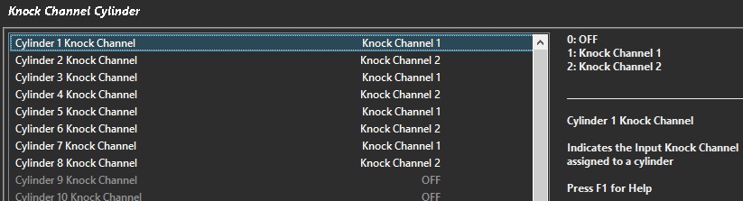
Example - V8 Chev LSA with two knock inputs
Knock Control Setup
Tuning Knock Control
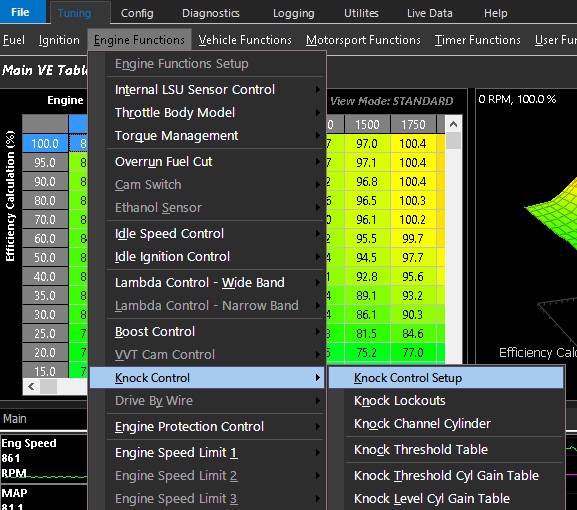
Tuning -> Engine Functions -> Knock Control -> Knock Control Setup
Knock Control Setup
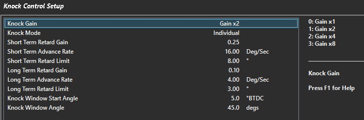
- Knock Gain - Gain added to knock signal (can multiply)
- Knock Mode - 0 = Global 1 = Individual (allows ECU to detect per cyl)
- Short Term Retard Gain - Retard for each percentage over the knock threshold
- Short Term Advance Rate - Rate at which timing is reintroduced when Short Term Retard is 0
- Short Term Retard Limit - Maximum Short Term Retard that can be applied
- Long Term Retard Gain - Long Term Retard applied based on Short Term Retard
- Long Term Advance Rate - Rate at which timing is reintroduced to Long Term Trim when Short Term Retard is 0
- Long Term Retard Limit - Maximum Long Term Retard that can be applied
- Knock Window Start Angle - Point at which ECU will start to sample the Knock Signal
- Knock Window Angle - The length in degrees in which the ECU will sample the Knock Signal
** Knock Window Angle must be less than the angle between TDCs
<90 degrees V8

<60 degrees V12
Knock Lockouts
- RPM Lo Lockout - Knock Control will be OFF below this RPM
- RPM Hi Lockout - Knock Control will be OFF above this RPM
- Post Start Delay - Delay in which Closed Loop Knock detection is active
- TP Lockout - Minimum Throttle Position before Knock detection is active
- dTP Lockout - Maximum Throttle Rate of Change in which Knock detection can become active
- dMAP Lockout - Maximum Manifold Pressure Rate of Change in which Knock detection can become active
- User Lockout - Allows user to create custom lockout channel
Knock Channel Cylinder
Select the appropriate Knock Channel (Knock Sensor) for each cylinder
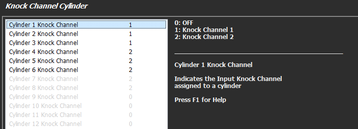
Example - 6 cylinder with two knock inputs
Knock Threshold Table
Table in which the maximum allowable measured Knock Level is allowed
Knock Threshold Cyl Gain Table
Used to multiply the signal gain per cylinder
** The X-Axis MUST be set to the Cylinder Numbers
Knock Level Cyl Gain Table
Used to multiple the knock level per cylinder
** The X-Axis MUST be set to the Cylinder Numbers
Knock Control
Knock Control Introduction
All Emtron ECU’s have Knock control, using inputs from a piezoelectric sensor. The ECU monitions the knock level for individual cylinders over a user defined crank angle window.
Each knock input is fully differential, giving superior common-mode noise rejection in the harsh automotive environment. The ECU starts by passing the analog signal from the knock sensor (piezoelectric) through an anti-aliasing signal conditioning filter before using Bosch integrated circuit technology for advanced digital signal processing. The digital filter is a fully programmable finite impulse response (FIR) filter allowing the user to adjust both the centre frequency and bandwidth. This is extremely powerful and very flexible, allowing the user to customise the filter design to suit the application.
Hardware Specification
- SL4 - Single knock input
- SL8/KV8/12/16 - Dual knock input
Knock Control Function Enable
Config ->Functions -> Function Output Setup -> Engine Functions -> Knock Control
Or
Utilities ->Knock Studio ->Knock Control
Disabled = Function is switched off
Enabled = Function is switched on
Filter Window Type
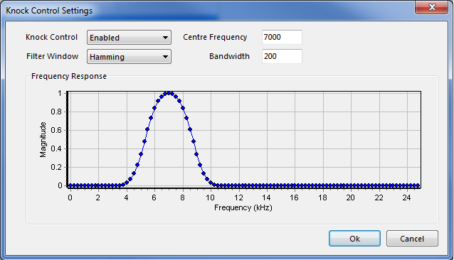
The effects of Filter Window can be visually seen when the different options are selected. It is a complicated topic, but basically a Window function is used to limit the signal in time and generate a different frequency response. The Hamming window provides tighter bandwidth control, requiring the centre frequency to be more accurate. The Blackman has a slightly more relaxed bandwidth by comparison and therefore the centre frequency is not as critical.
- None = Using raw Digital Filtering with no windowing
- Hamming
- Blackman
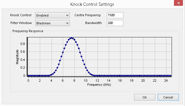
Centre Frequency = Central frequency the knock control will operate at. This is the dominant frequency the engine is expected to knock at.
An estimation or initial guess of the knock frequency can be done using this basic equation. This is ONLY a starting point and should be verified on the vehicle.
Knock Frequency(Hz) = 1800 x 1000 = 1800 x 1000
Piston Circumference(mm) 3.14 x Piston Diameter (mm)
Example . Piston Diameter 85mm. Knock Frequency = 1800 / (3.14 x 85mm) x 1000 = 6744 Hz
Bandwidth = Defines the frequency range (higher = wider) over which the knock control will operate. Outside that range all knock signals will be ignored. The engine will never knock at exactly the same frequency every time due to changes in combustion pressure and temperature, so the correct bandwidth is important. Too small and important knock events might be missed, too big and normal engine noise may contaminate the knock data. Typical values are recommend at 200 - 400Hz.
The below example shows the setup for a Centre frequency of 7000Hz and Bandwidth if 200Hz.
Knock Control using the 2nd harmonic
Sometimes an engines noise profile at the base frequency or 1st harmonics shows an indistinguishable difference between a knock event and normal engine noise. In this situation the 2nd harmonics (double the base frequency) can be used to achieve a better signal to noise ratio on a true knock event.
For example a Subaru engine has a knock frequency (1st harmonic) of approximately 6.0Khz. The second Harmonics would therefore be 12.0khz. If the engine noise profile at 6.0Khz showed an indistinguishable difference between a knock event and engine noise, the centre frequency off 12.0Khz could be used.
NOTE:
- There are 2 types of knock sensors, “wide-band” and “tuned”. Wide-band sensor will work over a range of 0 -20Khz, whereas a “tuned” sensor is designed to have a resonant frequency, producing a larger output level at the one frequency.
- Tuned knock sensors usual operate at the 2nd harmonic
Knock Cylinder Gain Tables
Knock Threshold Cyl Gain Table
This table is used to apply a multiplication factor to the knock threshold applied to cylinders individually.
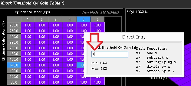
The default table value is 1.00 giving equivalence to the Knock Threshold Table
By adjusting this table, one can bend the knock threshold across an alternative runtime and also each cylinder individually.
The Y-Axis can spanned across any runtime or disabled
** The X-Axis MUST be set to the Cylinder Numbers
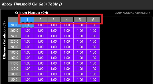
Example show - Porsche 996
This table is user defined and should only be adjusted and validated by an experienced tuner.
Knock Level Cyl Gain Table
This table is used to multiply the knock level measured at each cylinder individually
This is table is commonly used to effectively quieten noisy cylinders in relation to others to enable the use of a tight knock overall knock threshold.
By adjusting this table, one can bend affect volume of the knock signal source across an alternative runtime and also each cylinder individually.
Agani, the Y-Axis can spanned across any runtime or disabled. This table can be used on it’s own or together with the (Above) Knock Threshold Cyl Gain Table
This table is user defined and should only be adjusted and validated by an experienced tuner.
** The X-Axis MUST be set to the Cylinder Numbers
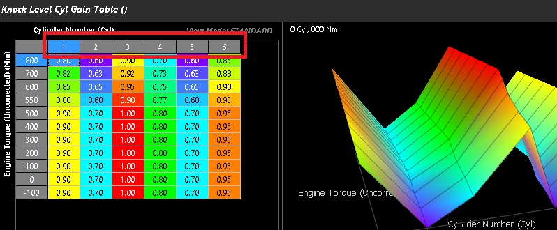
Example show - Porsche 996 spanned against uncorrected engine torque
Knock Lockouts
Knock Lockouts
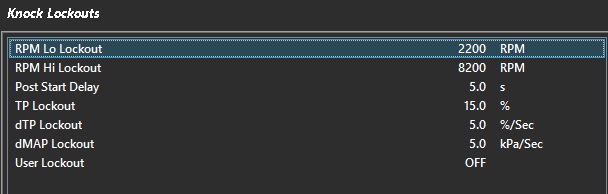
- RPM Lo Lockout - Knock Control will be OFF below this RPM
- RPM Hi Lockout - Knock Control will be OFF above this RPM
- Post Start Delay - Delay in which Closed Loop Knock detection is active
- TP Lockout - Minimum Throttle Position before Knock detection is active
- dTP Lockout - Maximum Throttle Rate of Change in which Knock detection can become active
- dMAP Lockout - Maximum Manifold Pressure Rate of Change in which Knock detection can become active
- User Lockout - Allows user to create custom lockout channel
Knock Studio
Knock Studio
The ECU uses a high precision digital filter to detect engine knock. To achieve high accuracy the center frequency and bandwidth of the filter are controlled from this menu.
A Filter Window is a mathematical function that overlays the filter design helping to enhance the filter design. This effect of these different windows can be viewed using this Knock Studio. Testing different windows is recommend to select the option that gives the best signal to noise ratio.
Once the filter design is complete, pressing Ok allows the filter coefficients to be calculated and the Knock Control system is ready to be used.

Knock Threshold Table
Knock Threshold Table
This table defines the permissible maximum measured Knock Level
That is, in the logger, the knock threshold is the value (or line) that once crossed is considered knock.
If this table is set too high, knock will not be detected.
Both the X & The Y-Axis can spanned across any runtime or disabled
Engine Torque (Uncorrected) & Engine RPM are commonly used (See example below)
This table is user defined and must be validated by the tuner.
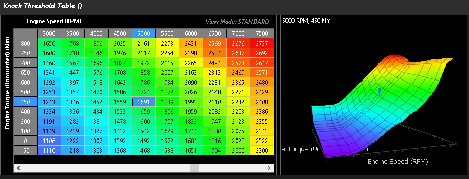
Example Shown - Porsche 996 (Uncorrected engine toque spanned against rpm)