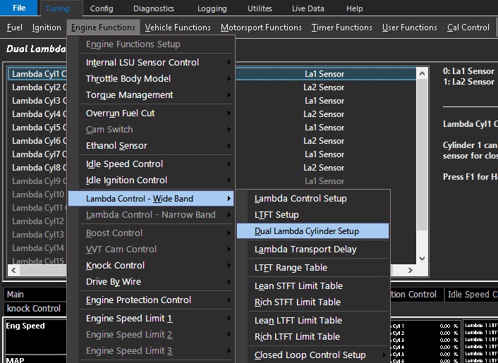
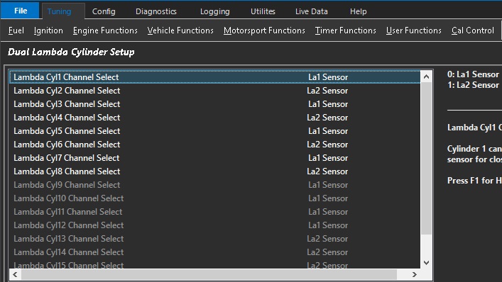
** Normally corresponds to which bank the Lambda sensor is installed in.
** Does not correspond to Bank Cylinder Setup
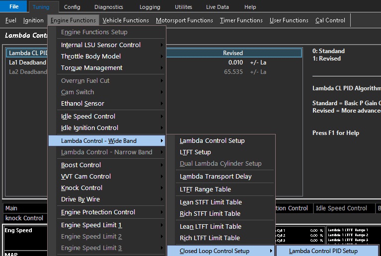
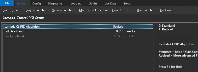
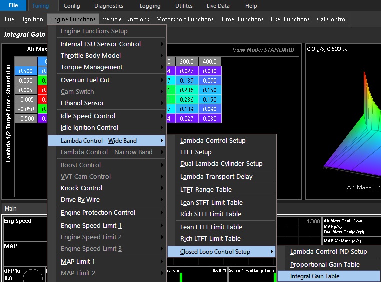
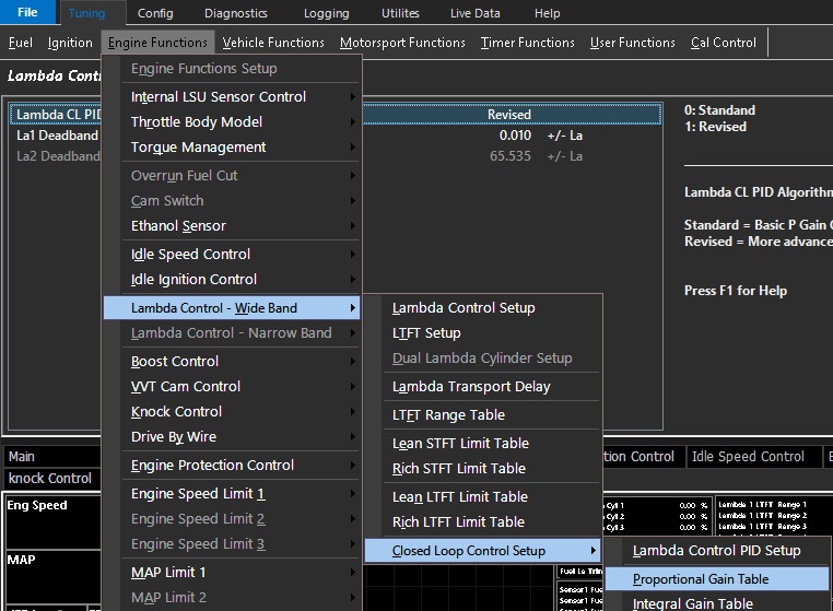
Lambda Control PID Setup
Lambda Control PID Setup
0 - Standard = Basic P Gain Controller
1 - Revised = More advanced PI Gain Controller
La1 Deadband - Deadband for CL to operate within for Lambda Sensor 1
La2 Deadband - Deadband for CL to operate within for Lambda Sensor 2
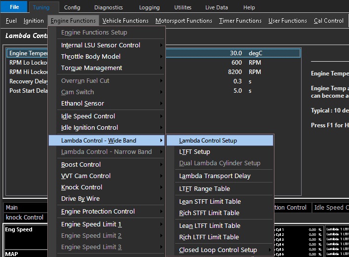
Lambda Control Setup
Lambda Control Setup
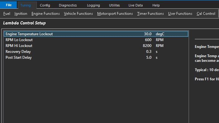
Engine Temp Lockout - Engine temp above which Lambda Control can become active
RPM Lo Lockout - Lambda control will be switched OFF below this RPM
RPM Hi Lockout - Lambda control will be switched OFF above this RPM
Recovery Delay - Delay in which Lambda Control can become active once within the lockout criteria
Post Start Delay - Delay in which Lambda Control can become active after start up
d**** NOTE: When using the Internal Lambda the Closed Loop will not start until either or both sensors are ready to operate.
Lambda Control - Wide Band
Lambda Control - Wideband
All Emtron ECU’s can support closed loop wideband lambda control using various methods. KV series ECUs have two internal wideband control systems that allow the user to wire lambda sensors directly to the ECU. In addition to this, Emtron ELC (Emtron Lambda to CAN) devices may be connected over CAN networking (included in all Emtron ECUs), and even an external Lambda controller that has a standard AV output can be used.
Hardware specification
SL4/SL8 - No internal lambda control. Use ELC, standard AV, user CAN
KV8/12/16 - Dual internal lambda control, and/or ELC, standard AV, user CAN
Select the control system and appropriate outputs:
Config View -> Function Setup -> Engine Functions -> Closed Loop Lambda Control
OFF = Function is switched off and the selected output channels are deallocated.
ON = Function is switched on
Function Type
Wideband Control – Lambda 1 Channel = Single Lambda input using Lambda Channel 1
Wideband Control – Lambda 2 Channel = Single Lambda input using Lambda Channel 2
Wideband Dual Control (La1 + La2) = Dual Lambda inputs using Lambda Channel 1 and 2
Narrowband Control – Sensor 1 = Single narrowband input on channel 1(See Narrowband Lambda)
Narrowband Control – Sensor 2 = Single narrowband input on channel 2 (See Narrowband Lambda)
Dual Narrowband Control (Sensor 1+2) = Dual narrowband input on both channels (See Narrowband Lambda)
Input Channel Selection
Emtron Lambda inputs must be defined under input selection.
CAN ELC #x Ch-x - Defines which ELC channel to use (See Emtron ELC)
ANV x - Define and calibrate as standard AV input
CAN Lambda x - Define input as user received CAN input (see CAN Bus)
CAN NTK EL-4 x - For use with NTL Lambda Controller EL-4
Input options
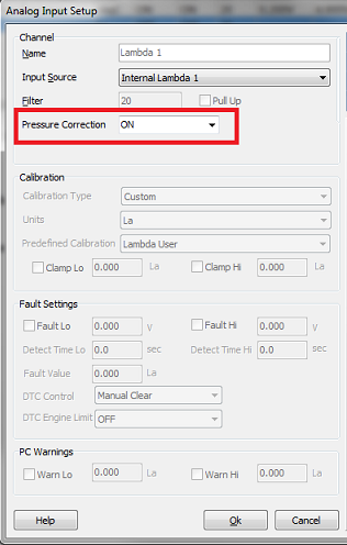
Pressure Correction - Lambda sensors can have EMAP compensation enabled (see Exhaust Back Pressure)
Calibration Type - Select Custom for configuring ANV input, or Predefined if using internal Lambda controller,
Emtron ELC, or NTK EL-4
Predefined Calibration - Select LSU internal or NTK EL-4
Lambda Transport Delay Guide
Lambda Transport Delay Tuning Guide
The Lambda Closed Loop system is a fairly standard PID routine (with Proportional, Integral, and Derivative gains). See the Lambda Control - Wide Band section for more details
However, for it to function correctly, latency from o2 sensors signals must be programmed/tuned into the ECU system. This is known as “Lambda Transport Delay”
** Physical location/distance from the engine or pre-/post-turbo configuration of o2 sensors will affect transport delay
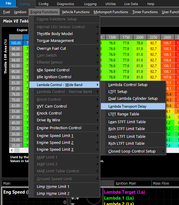
Tuning -> Engine Functions -> Lambda Control - Wideband -> Lambda Transport Delay
Tuning Lambda Transport Delay
Lambda Transport Delay is often confused as a measurement of time it takes for the lambda to reach lambda targets (once lambda is changed), however
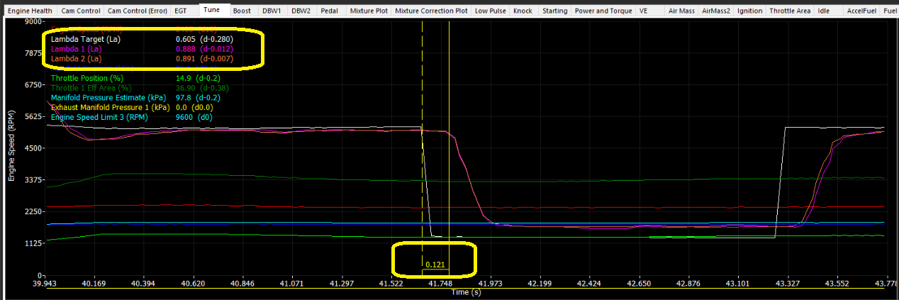
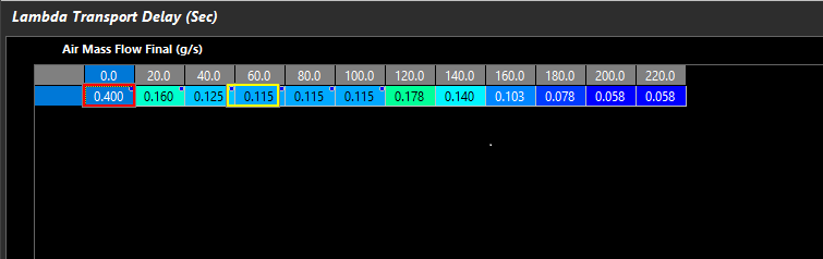
Lambda transport delay = the time (in seconds) measured it takes for the lambda to start once target has changed
A simple way to tune this function is to put the engine at varying loads and make lambda target change while logging. Measure with the differences cursor (“D”) in the logger to see the time it takes for the lambda to change from the original value to the new value. This is your “Lambda Transport Delay”
Next, populate the transport delay value (in seconds), into the “Lambda Transport Delay” table.
** Example shown is 2D following Air Mass Flow Final (g/s) - but a 3D table axis is available for using standard values such as RPMxMAP, etc.
Repeat the process for varying loads to populate the transport delay table
Lambda Transport Delay
Lambda Transport Delay
3D table that defines the delay in which the Lambda sensor reports its input
** A sensor placed very far down the exhaust stream will have a larger delay
** Transport delay is dependent on engine load. Higher exhaust velocity reduces delay
Axis is spanned via RPM x TP. Any runtime can be used
***Transport delay can affect closed loop fuel PID routine.
Tuning Tip:
The Lambda Transport Delay table time factor can be validated using the Emtune Logger by changing the Lambda Target table at varying loads.
By utilizing the Differences mode of the logger to measure the time it takes for the Lambda to start changing after the Lambda Target table is manipulated, you are able to verify & validate your Lambda Transport Delay Table time factor is correct.
Bare in mind, once the engine is tuned. IE: The VE table agrees with the Lambda Target Table.
The VE table then becomes the feed forward value for the closed loop Wideband Lambda control PID routine.
The more accurate your transport delay table is. The better your closed loop Wideband Lambda control will be.
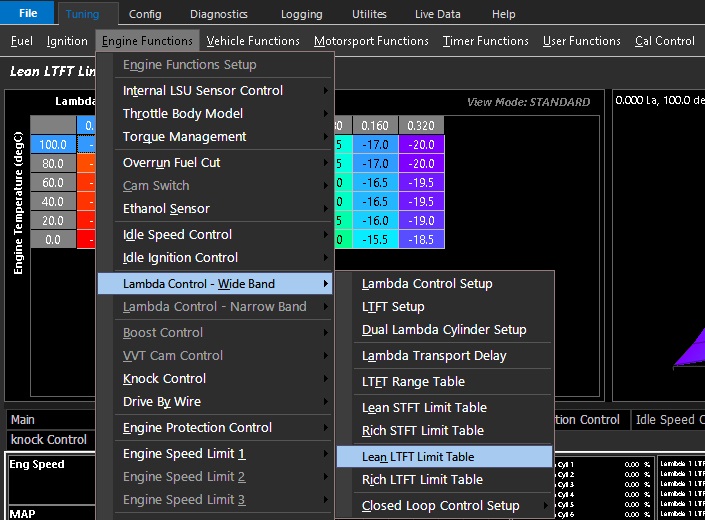
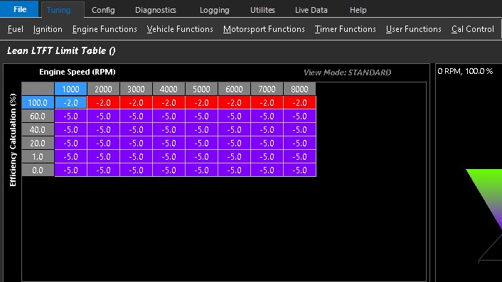
Units define the maximum lean (negative) compensation for closed loop fueling
Axis configuration is open. Example shows limited fuel trimming under higher engine loads.
LTFT Range Table
LTFT Range Table
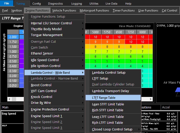
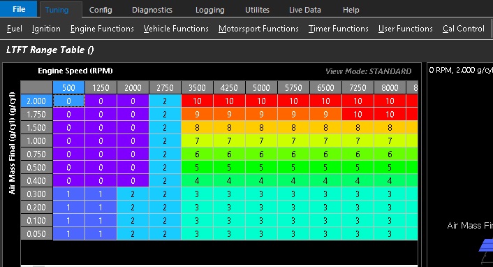
There are 10 ranges which can be set by the user in a 3D table. Each number defines a range.
Each range allows for storage of LTFT values.
This allows the user to define “zones” so that different LTFT learning values do not affect each other, but also allow the trims to be fed forward appropriately
When in this range the LTFT looks at the STFT and loads values for these ranges.
A value of “0” disables the LTFT for that zone
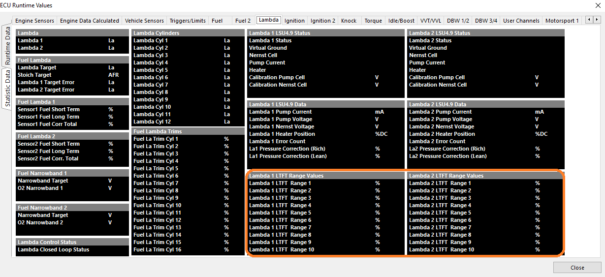
LTFT Range Values can be viewed in Runtimes under Lambda as well
** Note - LTFT Range Values clear on ECU Power Cycle
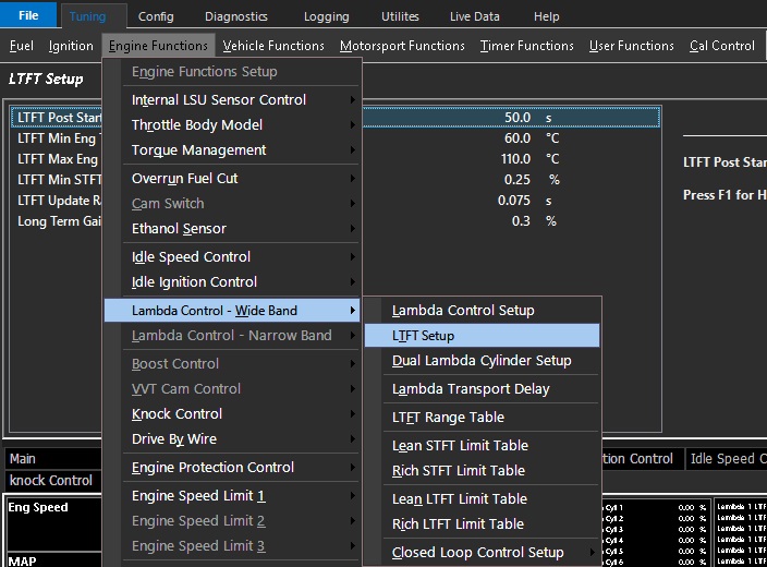
LTFT Setup
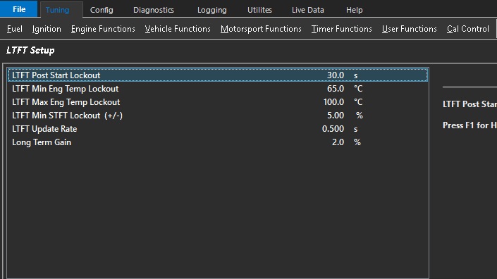
LTFT Setup (Long Term Fuel Trim)
LTFT Post Start Lockout - Delay in which LTFT can become active after start up
LTFT Min Eng Temp Lockout - Minimum engine temperature for LTFT to become active
LTFT Max Eng Temp Lockout - Maximum engine temperature for LTFT to become active
LTFT Min STFT Lockout (+/-) - The minimum STFT allowed before LTFT can start correcting
LTFT Update Rate - Update rate for LTFT
Long Term Gain - Percentage of STFT applied per second
** For STFT Lockout -
Min STFT Lockout = +/- 2.5% The LTFT will start operating when the STFT is greater the 2.5% or less than -2.5%
** For Long Term Gain -
The Gain is percentage of the short term trim applied per second.
Example: Short Fuel Trim = 10.00%
Long Term Gain = 2.0%
Long Term Fuel Trim = 2.0% of 10.00% per second
Long Term Fuel Trim = 0.20% per second
Lambda LSU4.9 Sensor Control
Introduction
The KV series ECU has the ability to interface directly to a Bosch Lambda Sensor(s), model LSU4.9.
To achieve the optimal control of this sensor, the ECU uses a genuine Bosch Integrated Circuit technology. It provides very accurate data on pump current which equates to Lambda
and also Nernst Cell Temperature which is used for precise heater control.
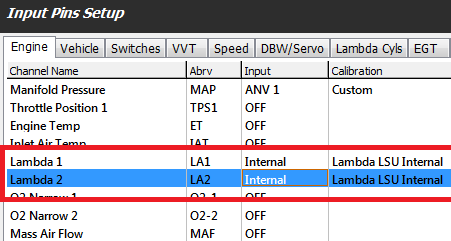
The ECU assigns the correct the Heater Output Channel based on ECU Type and Serial Number. The only setup required to enable the Internal Lambda 1 or 2 control is from the Config View -> Inputs-> Engine tab.
If “Lambda 1” Input Channel has the Input Source selected to “Internal Lambda 1” the function becomes enabled.
If “Lambda 2” Input Channel has the Input Source selected to “Internal Lambda 2” the function becomes enabled
Adjustments to the operation of On-board Lambda Sensor Control can be made from the Tuning view -> Engine Functions -> Internal LSU Sensor Control
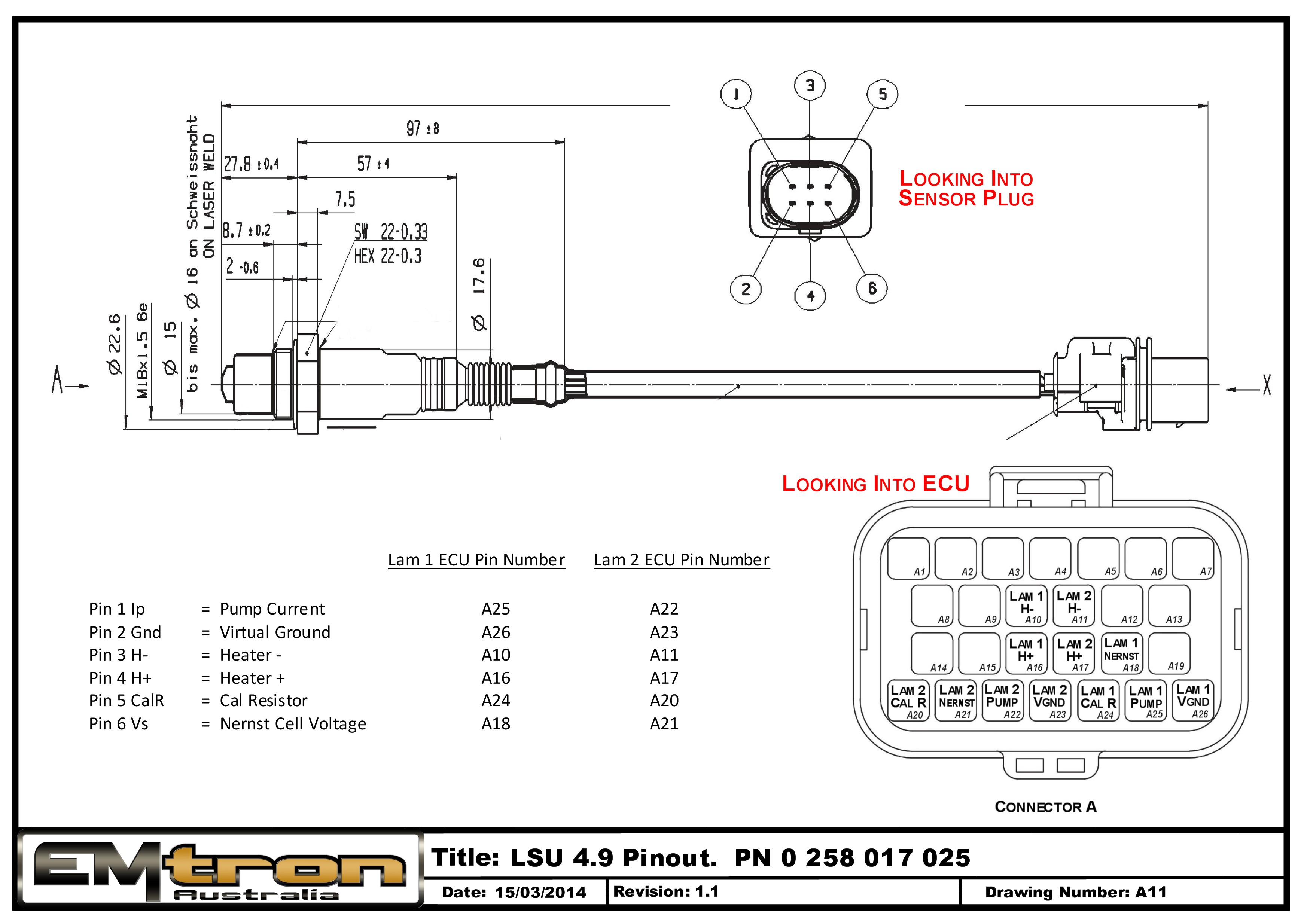
The ECU uses all 6 sensor wires per sensor.
Sensor Shock
In some situations during normal operation, the sensor will temporally shutdown for between 0.5 sec to 2.5 secs. This is usually caused by a combination of sensor incorrect placement and Fuel type resulting in the sensor being “shocked” ; either thermally or by a pressure wave inside the exhaust system. For the correct sensor placement please read the Sensor Installation and Wiring topic.
Although the sensor shutdown is outside the ECU’s control, the status is constantly monitored. In the event of a shutdown the heater control is put into a Hold mode as it the Closed Loop Lambda.
Exhaust Back Pressure
Wideband Lambda sensors primarily count oxygen atom numbers through measuring the oxygen ion current within the sensors pump cell. The exhaust gas pressure affects this oxygen ion current – more pressure means more atoms per unit volume and a higher pump current at the same Lambda.i.e will cause the sensor to read farther from stoichiometric
A rich reading will appear richer than it really is.
A lean reading will appear leaner than it really
This predominantly becomes an issue in Turbocharged applications. This is the main reason you should position the sensor after the turbo where exhaust back-pressure is lowest.
When measuring Exhaust Back Pressure an Absolute Pressure Sensor MUST be used. (i.e do not used a Gauge Pressure Sensor)
The ECU can applied EMAP correction when enabled. This ONLY applies when the Internal LSU4.9 control is used. This correction is not available to data on Analog inputs or CAN channel as it requires precise correction the sensors Pump Current.
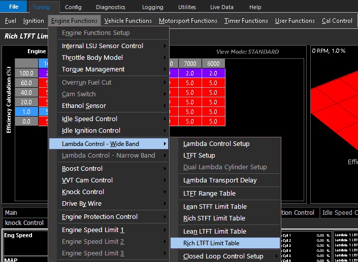
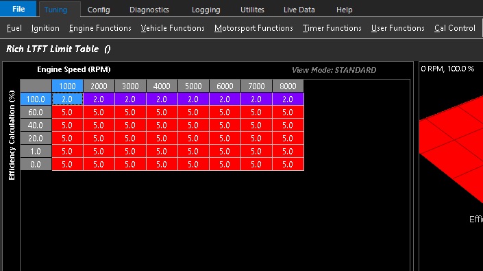
Rich LTFT Limit Table
Rich LTFT Limit Table
Units define the maximum Rich (positive) compensation for closed loop fueling
Axis configuration is open. Example shows limited fuel adding under higher engine loads.
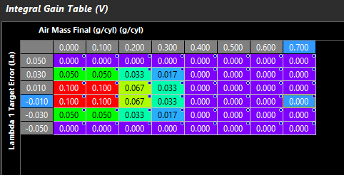
Integral Gain Table
Integral Gain Table
Integral gain controls how much adaptive correction is needed over time.
0.1 is a good starting value
** Above example shows under higher engine loads Integral is phased out and under higher lambda target error. This is to help eliminate Integral corrections from interfering with Proportional correction
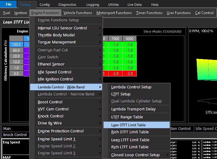
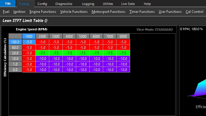
Lean STFT Limit Table
Lean STFT Limit Table
Units define the maximum lean (negative) compensation for closed loop fueling
Axis configuration is open. Example shows limited fuel trimming under higher engine loads.
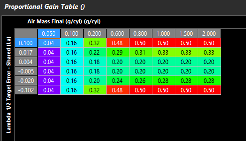
Proportional Gain Table
Proportional Gain Table
Proportional Gain controls how aggressive instantaneous correction is based on the current target error vs Transport Delay
** When using Dual Lambda Control - Lambda 1/2 Target Error - Shared must be used for the gain table to operated on the individual sensors
** Transport Delay must be set correctly
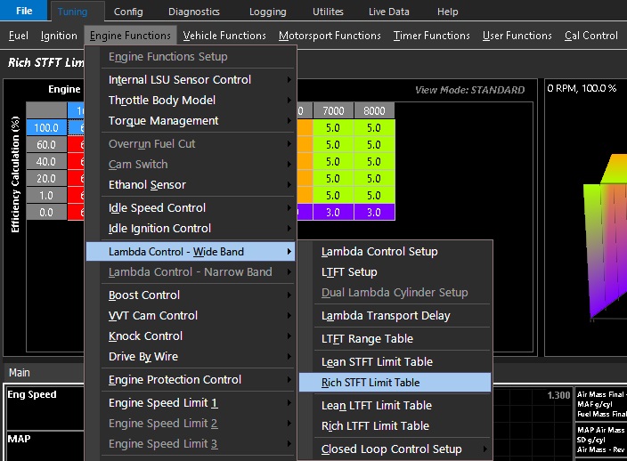
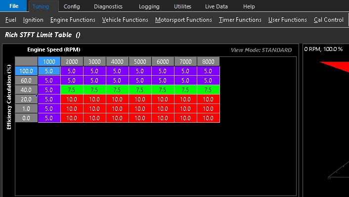
Rich STFT Limit Table
Rich STFT Limit Table
Units define the maximum Rich (positive) compensation for closed loop fueling
Axis configuration is open. Example shows limited fuel adding under higher engine loads.
Heater Control and Sensor Calibration
Heater Control
During engine start-up, condensation forms in the exhaust which may damage the sensor. It is recommended to only start heating the LSU sensor after the engine is running and the moisture content in the exhaust has evaporated. The ECU has settings to prevent this damage; “Heater RPM Lockout” and “Heater Post Start Lockout”
Typical Values:
Heater RPM Lockout = 500 RPM
Heater Post Start Lockout = 4.0 Sec
Calibration
The sensor is calibrated automatically by the ECU on power up. During the calibration process two important pieces of data are read:
The optimal Nernst Cell Temperature which is used for sensor heater control. The ELC applies duty cycle and a PID routine to maintain a constant and accurate heater temperature which results in a very stable and accurate Lambda value.
The Pump Current that corresponds to a Lambda reading of 1.000 Lambda.
NOTE: A Free-Air Calibration is NOT required on the LSU4.9. The sensor uses a reference pump current instead of reference air. The big advantage with this is that the reference is a calibrated electrical signal and remains constant.