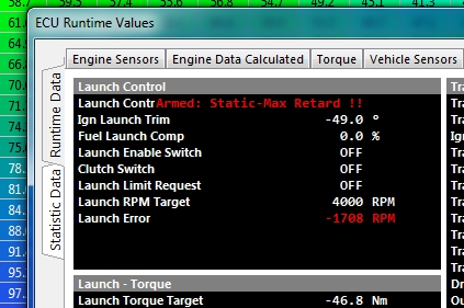
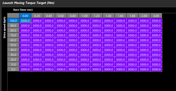
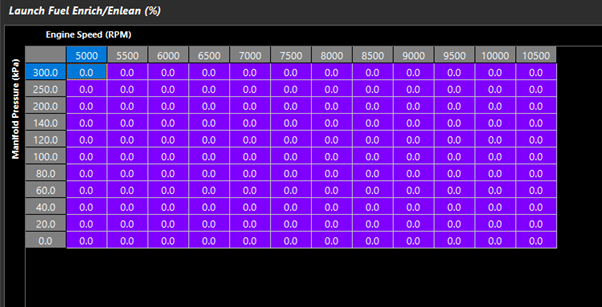
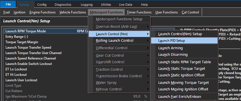
Balancing “Torque Reduction – Retard” vs “Torque Reduction – Cut” is important when using both static and moving target modes for PID Launch Targeting.
Generally, timing retard is good for control of torque and can also help spool turbines in those applications.
However, during launch, as engine load/boost increases the potential engine torque, ignition timing can/will continue to retard to overcome engine speed from increasing.
** EGT, Turbine speed, and boost pressure must be considered, to determine the Static/Moving Ignition Retard Clamp points in their respective tables.
At these points of ignition trim/retard, the Launch system will switch to Launch Torque Reduction – Cut functions.
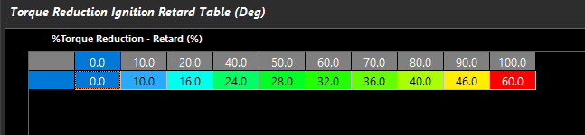
The channel correlates to how much retard will be applied vs the amount of Torque Reduction requested.
This is a global function of the ECU, which is why it is under the Torque Management section.
** Warning - The maximum value in this table (at 100% %Torque Reduction – Retard), must be at a higher value than the Static/Moving Ignition Retard Clamp
Static Mode Example Data:
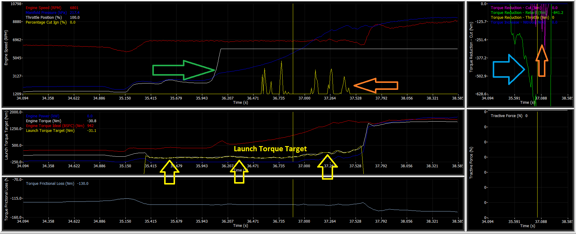
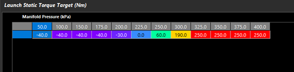
In the above static example, you can see the ECU holding the “Launch Torque Target” (Yellow Arrows) in the second plot.
This is done by Torque Reduction – Retard (Blue Arrow), until the load is increased by throttle and boost (Green Arrow).
The Launch Control system automatically controls the Launch Control Target with the required additional Torque Reduction Cut under the higher loads to control the Launch Torque Target (Orange Arrow).
Cuts are introduced once the Static Ignition Retard Clamp is reached.
Moving Mode Example Data:
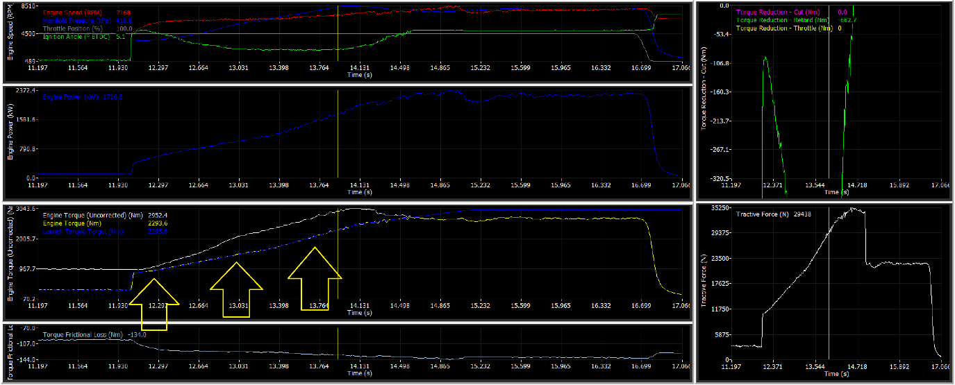
In this moving target example, the ECU is holding “Launch Torque Target” (Yellow Arrows) in the second plot by Torque Reduction – Retard alone.
With a properly tuned Throttle Area table (Throttle Mass Flow), the ECU can calculate the outflow requirement for desired torque requests
In some cases depending onm the hardware, an open loop a timing retard table can be applied to generate “reserve” torque as well in Turbocharged applications.
** EGT, Turbine speed, and boost pressure should be considered
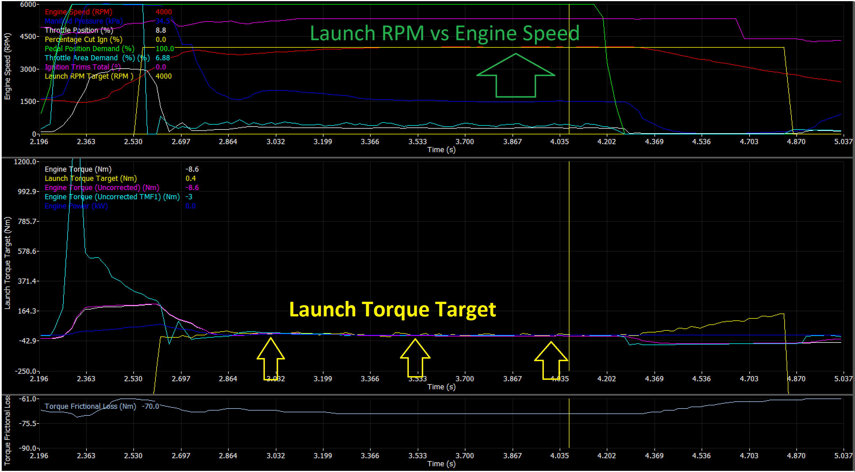
Static Mode Example Data:
In the above static example, you can see the ECU holding the “Launch Torque Target” (Yellow Arrows) in the second plot.
This is done by adjusting final torque via Engine Torque (TMF) channels
Launch Arming
Launch Arming
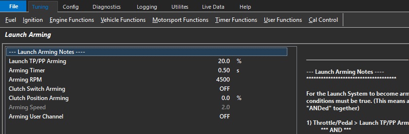
Launch Arming Notes:
For the Launch System to become armed ALL the following conditions must be true.
(This means all these conditions are “ANDed” together)
Throttle/Pedal > Launch TP/PP Arming
*** AND ***
Engine Speed > Arming RPM
*** AND ***
Clutch Switch Status = ON (when enabled)
*** AND ***
Clutch Position > Clutch Position Arming (when enabled)
*** AND ***
Speed > Arming Speed
*** AND ***
User Channel = ON (when enabled)
*** AND ***
Arming time > Arming Timer settings (s)
Launch TP/PP Arming
The Launch Control system will be ready for arming when the TPS1 or PPS1 (if assigned) is above this value.
***NOTES ***
1: All remaining Arming Conditions MUST be be satisfied before the Launch Control becomes armed.
The “Launch TP/PP Arming” setting MUST be greater than the “Launch TP/PP Disarming” setting.
0.0% = OFF
Clutch Switch Arming
Enables the Clutch Switch as an arming input for the Launch Control System. (Clutch Switch Status = ON)
***NOTES ***
1: All remaining Arming Conditions MUST be be satisfied before the Launch Control becomes armed.
2: Clutch Switch Input Channel MUST be configured
0 = OFF
1 = ON
Arming Timer
Once all the arming conditions are meet this timer will start. After this time is past the Launch Control system will become Armed.
0 = OFF.
Arming RPM
The minimum engine speed to exceed to arm the Launch control system.
***NOTES ***
1: All remaining Arming Conditions MUST be be satisfied before the Launch Control becomes armed.
The “Arming RPM” setting MUST be greater than the “Disarming RPM” setting.
0 = OFF
Clutch Position Arming
The minimum clutch position percentage to arm the Launch control system. Values above this amount are armed
***NOTES ***
1: All remaining Arming Conditions MUST be be satisfied before the Launch Control becomes armed.
The “Clutch Position Arming” setting MUST be greater than the “Clutch Position Disarming” setting.
100.0% Position = Clutch fully depressed
0 = OFF
Arming Speed
The Launch Control speed reference channel input source value below which the Launch Control system is armed
This ensures the vehicle is stationary or near stationary for Launch Control arming.
***NOTES ***
1: All remaining Arming Conditions MUST be be satisfied before
the Launch Control becomes armed.
Arming User Channel
Create a custom Arming method from a User Function.
The Launch Control system will be ready for arming when the User Channel is ON.
***NOTES ***
1: All remaining Arming Conditions MUST be be satisfied before the Launch Control becomes armed.
0: OFF
1: User Output Channel 1
2: User Output Channel 2
3: User Output Channel 3
4: User Output Channel 4
5: User Output Channel 5
6: User Output Channel 6
7: User Output Channel 7
8: User Output Channel 8
9: User Output Channel 9
10: User Output Channel 10
.
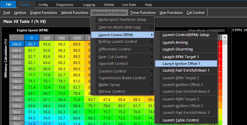
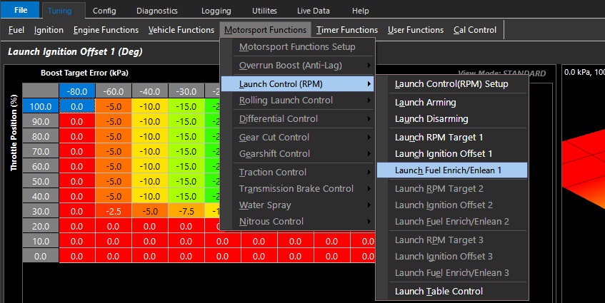
Launch Ignition Offset 1/2/3 (Deg)
Launch Ignition Offset 1/2/3 (Deg)
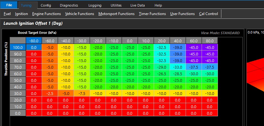
The Launch Ignition Offset Table is used to set the ignition retard applied when the Launch Control System is Armed.
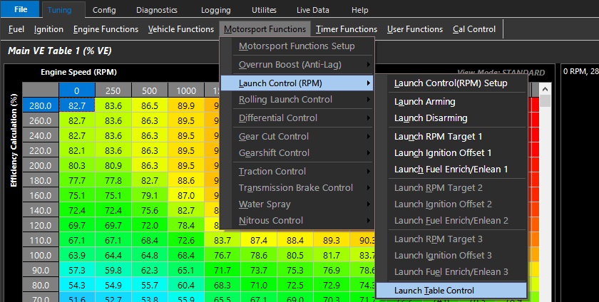
Multiple or alternative Launch Ignition Offset tables can be activated via Launch Table control.
Tables are user defined.
Launch Control
Launch Control Config
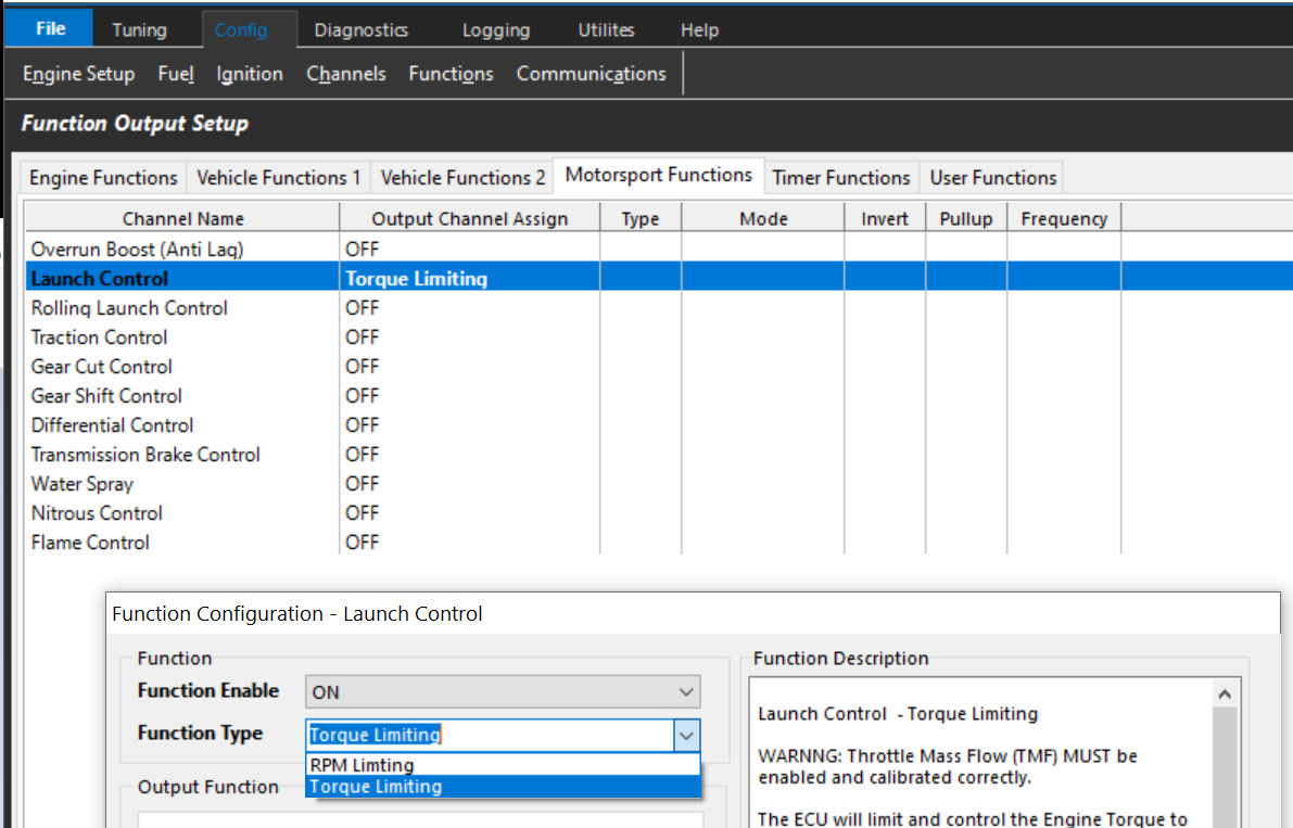
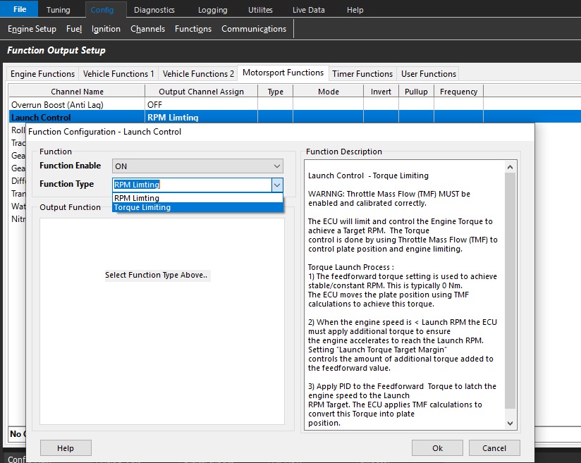
The following 2 modes are available for Launch Control:
RPM Limiting
Torque Limiting
RPM Limiting
This is a conventional RPM limiting mode where where ECU adjusts the engine cutting to achieve a target Launch RPM.
Torque Limiting
The ECU will limit and control the Engine Torque to achieve a Target RPM. The feedforward torque setting is used to achieve stable/constant RPM which
is typically 0 Nm. The ECU then applies a PID over the top to latch the engine speed to the Launch RPM Target.
The methods used by the ECU to control torque are user adjustable with the following options:
DBW Plate Control(PID) + Ignition Retard(Table). The ECU will calculate the required DBW Throttle Area for the RPM Target/Torque Request and move the plate to the position. The ECU is able to calculate the plate position using the TMF calculations so this function MUST be calibrated correctly. An Ignition retard table can be used in an open-loop setup to reduce torque and the ECU will automatically correct for this torque loss during the TMF throttle plate calculation.
This mode is most suitable for road applications
Engine Cutting(PID) + Retard(Table). The ECU will PID the Torque Target (closed loop) to achieve the correct Launch RPM Target. An Ignition retard table can be used in an open-loop setup (non ECU calculated) to help reduce Torque and spool turbos. The PID closed loop system will account for this Torque loss during the Engine Cut calculation.
This mode is most suitable for track applications
Ignition Retard (PID) + Cutting (PID). The is a fully closed loop system with the ECU calculating both the Ignition Retard and %Cut to achieve the Launch RPM/Torque target. The ECU calculates the Retard first until the Retard clamped is reached, then removes any remaining Torque with %Cut.
Controls when the Launch Torque Limit function will turn ON.
The Launch Torque Limit and PID control will switch ON when the RPM enters set range of the Launch RPM Target.
This is a negative engine speed value that sets the range below the Launch RPM Target
Once ON it will latch and remain ON until the system exits to standby mode
Exit of the Launch control is user defined in Launch Disarming
Example:
Launch RPM Target = 4000
Entry Range = -200
Rpm < 3800 Launch Control Torque Limit is OFF
Rpm >= 3800 Launch Control Torque Limit is ON
Torque Target Margin
This setting is used to increase/decrease the Engine Torque Target once the engine is within the Entry Range of the Launch RPM Target.
The margin is added to the Launch Torque target on entry and decays to the Launch Torque Target at a linear rate as the engine approaches the Launch RPM Target.
Tuning Tip:
Use 0Nm initially as a starting point. This setting is used to control the entry behavior.
*** If the engine is struggling to reach Launch Target, Increase Margin*
Example:
Launch RPM Target = 3000 RPM
Entry Range = -200 RPM
Launch Torque Target = 10 Nm
Launch Torque Target Margin = 100Nm
RPM < (Launch RPM Target - Entry Range ) the Torque Limit is OFF
RPM > (Launch RPM Target - Entry Range) the Torque Limit is latched ON
Rpm < 2800. Torque Limit OFF
Rpm = 2800. Torque Target = 10Nm + 100Nm = 110Nm
Rpm = 2850. Torque Target = 10Nm + 75Nm = 85Nm
Rpm = 2900. Torque Target = 10Nm + 50Nm = 60Nm
Rpm = 2950. Torque Target = 10Nm + 25Nm = 35Nm
Rpm = 3000. Torque Target = 10Nm + 0Nm = 10Nm
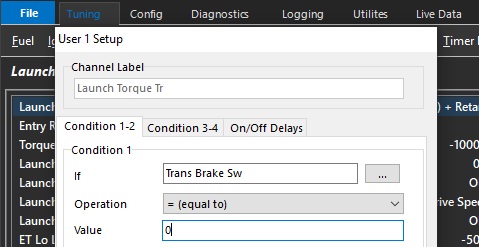
Launch Torque Transfer User Channel
Allows the User to control when the Torque Target transitions from “Static Torque Target” table to the “Launch Moving Torque Target”
***** This User MUST be set up or Launch Control will not enable***
Example:
Trans Brake Switch Status could be used as a user channel input to trigger the transition from Launch Torque Target to Launch Moving Torque Target
Launch Static Mode Speed Lockout
When the speed input is greater than this value, the Launch System will lockout the “Static Torque Target" and maintain the “Moving Torque Target". This prevents the accidental return of the launch system back into Static Mode.
** NOTE: Make sure the “Launch Speed Reference Channel” is set correctly **
Typical Value = 10 kph
Launch Speed Reference Channel
Defines the speed channel used to Disarm/Arm the Launch Control System.
0: OFF
1: Drive Speed
2: Ground Speed
3: Drive Speed Front L
4: Drive Speed Front R
5: Drive Speed Rear L
6: Drive Speed Rear R
7: Undriven Speed Front L
8: Undriven Speed Front R
9: Undriven Speed Rear L
10: Undriven Speed Rear R
11: Front Axle Speed
12: Rear Axle Speed
13: Vehicle Speed
14: Engine Speed
15: Input Shaft Speed
16: Output Shaft Speed
17: GPS Speed
Launch Enable Switch Lockout
When set to ON the Launch Switch can be used to activate the Launch Control System.
0: OFF
1: ON
ET Lo Lockout
This is an under-temperature lockout. The Launch Control system will be ready for arming when the Engine Temperature is greater than this value.
For the Launch System to be ready for arming the following must be true:
Throttle/Pedal > Launch TP/PP Lockout setting AND
Engine Temperature > ET Lo Lockout setting AND
Engine Temperature < ET Hi Lockout setting AND
User Lockout = ON (if enabled)
ET Hi Lockout
This is an over-temperature lockout. The Launch Control system will be ready for arming when the Engine Temperature is less than this value.
For the Launch System to be ready for arming the following must be true:
Throttle/Pedal > Launch TP/PP Lockout setting AND
Engine Temperature > ET Lockout setting AND
User Lockout = ON (if enabled)
Launch User Lockout
The Launch Control system will be ready for arming when the User Channel (if assigned) is ON.
For the Launch System to be ready for arming the following must be true:
Throttle/Pedal > Launch TP/PP Lockout setting AND
Engine Temperature > ET Lockout setting AND
User Lockout = ON (if enabled)
0: OFF
1: User Output Channel 1
2: User Output Channel 2
3: User Output Channel 3
4: User Output Channel 4
5: User Output Channel 5
6: User Output Channel 6
7: User Output Channel 7
8: User Output Channel 8
9: User Output Channel 9
10: User Output Channel 10
Launch Control (Nm)
Launch Control (Nm)
This function of launch control utilizes the “Torque Management” function of the ECU.
A PID loop is utilized when “Static” mode is functional to control engine torque to run against Launch RPM Target
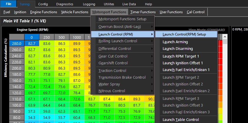
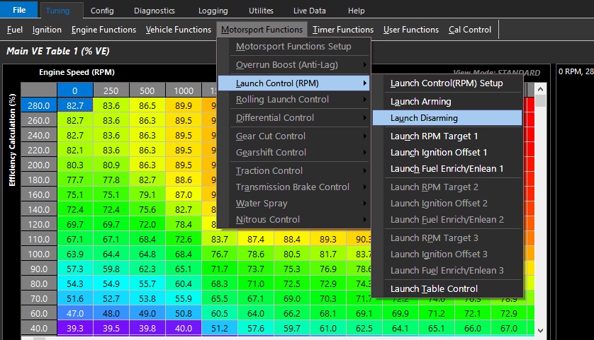
Launch Control (RPM) Setup
Launch Control (RPM) Setup
Launch Control modes of operation.
Always On. The Launch Control system is always ON.
Clutch Switch Only
Arming: When the Clutch switch is ON the Launch control is armed.
Disarming: When the Clutch is OFF the Launch Control is in standby.
Speed Only.
Arming: When the Speed is less than the " Arming Speed" the Launch Control is armed.
Disarming: When the Speed is greater than the " Disarm Speed" the Launch control is back into standby mode.
Clutch and Speed.
Arming: When the Clutch switch is ON AND the Speed is less than the " Arming Speed" the Launch Control is armed.
Disarming: When the Speed is greater than the " Disarm Speed" the Launch control reverts back into standby mode.
NOTE: The Clutch switch is not used during disarming
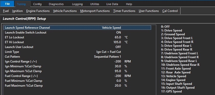
Launch Speed Reference Channel
Sets speed channel referenced by launch control function - can be used to arm/disarm the Launch control system.
0: OFF
1: Drive Speed
2: Ground Speed
3: Drive Speed Front L
4: Drive Speed Front R
5: Drive Speed Rear L
6: Drive Speed Rear R
7: Undriven Speed Front L
8: Undriven Speed Front R
9: Undriven Speed Rear L
10: Undriven Speed Rear R
11: Front Axle Speed
12: Rear Axle Speed
13: Vehicle Speed
14: Engine Speed
15: Input Shaft Speed
16: Output Shaft Speed
17: GPS Speed
Launch Enable Switch Lockout
When set to ON, the Launch Enable Switch can be used to enable/disable the Launch control system.
0: OFF
1: ON
The launch enable switch is found in the software: Config >Channels >Input Setup >Motorsport >Launch Enable switch
ET Lo Lockout
This is an under-temperature or low engine temperature lockout.
The Launch Control system will be ready for arming when the Engine Temperature is greater than this value.
This lockout references the Engine Temperature sensor
For the Launch System to be ready for arming the following must be true:
Throttle/Pedal > Launch TP/PP Lockout setting AND
Engine Temperature > ET Lo Lockout setting AND
Engine Temperature < ET Hi Lockout setting AND
User Lockout = ON (if enabled)
ET Hi Lockout
This is an over-temperature or high engine temperature lockout.
The Launch Control system will be ready for arming when the Engine Temperature is less than this value.
This lockout references the Engine Temperature sensor
For the Launch System to be ready for arming the following must be true:
Throttle/Pedal > Launch TP/PP Lockout setting AND
Engine Temperature > ET Lo Lockout setting AND
Engine Temperature < ET Hi Lockout setting AND
User Lockout = ON (if enabled)
Launch User Lockout
The Launch Control system will be ready for arming when the User Channel (if assigned) is ON.
For the Launch System to be ready for arming the following must be true:
Throttle/Pedal > Launch TP/PP Lockout setting AND
Engine Temperature > ET Lockout setting AND
User Lockout = ON (if enabled)
0 = Off
Launch Limit Type
This sets the type of launch limit to be applied to control the engine speed
0: Fuel Cut Only
1: Ign Cut Only
2: Ign Cut + Fuel Cut
Cut Pattern
Where the cut pattern for engine speed limiting is set.
0: Random Pattern 1
1: Random Pattern 2
2: Sequential Pattern 1
3: Sequential Pattern 2
Ign Control Range (-/+)
Sets the engine speed range above or below the launch target rpm limit where ignition cut control is applied
Negative values start to the cut the ignition below the launch target rpm limit
Example: -200 RPM
200 rpm before the cut target the minimum cut clamped value is applied
The ignition cut percentage increases to the maximum cut clamp value at the launch rpm limit
Positive values are above the launch target rpm limit
Example: +200 RPM
At the Launch target rpm limit, the minimum cut clamp percentage value is applied
The ignition cut percentage increases to the maximum cut clamp value at 200 rpm above the Launch target rpm limit.
Ign Minimum %Cut Clamp
Sets the minimum ignition cut clamp percentage applied at the start of the control range
Ign Maximum %Cut Clamp
Sets the maximum ignition cut clamp percentage applied at the end of the control range.
Fuel Control Range (-/+)
Sets the engine speed range above or below the launch target rpm limit where fuel cut control is applied
Negative values start to the cut the fuel below the launch target rpm limit
Example: -200 RPM
200 rpm before the cut target the minimum cut clamped value is applied
The fuel cut percentage increases to the maximum cut clamp value at the launch rpm limit
Positive values are above the launch target rpm limit
Example: +200 RPM
At the Launch target rpm limit, the minimum cut clamp percentage value is applied
The fuel cut percentage increases to the maximum cut clamp value at 200 rpm above the Launch target rpm limit.
Fuel Minimum %Cut Clamp
Sets the minimum fuel cut clamp percentage applied at the start of the control range
Fuel Maximum %Cut Clamp
Sets the maximum fuel cut clamp percentage applied at the end of the control range.
Launch Control Tuning Guides
Launch Control Tuning Guides
Preliminary information:
For Torque Based Launch Control to work properly, the ECU torque calculations must be correct.
The calibration file must have accurate VE calculations, fuel injector data, etc.
Frictional loss tables of the engine are crucial for the correct torque calculations.
There are three methods of Torque Reduction that can be used regarding Launch Control.
Retarding ignition timing, cutting, or throttle area vs torque reduction % will reduce torque of the engine.
There are 3 different Launch RPM Torque Modes that can be selected in Launch Control Setup (See Launch Control Setup).
Option 0: RPM control using Throttle Mass Flow + Retard.
The ECU will calculate the required throttle area for the RPM target and move the plate to the position. Ignition retard Torque loss will be factored into the calculation to give the correct plate position.
Option 1: RPM control using Cutting(PID) + Retard(Table).
The ECU will PID the Torque Target (closed loop) to achieve the correct Launch RPM Target. An Ignition retard table can be used in an open-loop setup (non ECU calculated) to help reduce Torque and spool turbos. The PID closed loop system will account for an Torque loss due the to retard.
Option 2: RPM control using Retard(PID) > Cutting(PID)
The is a fully closed loop system with the ECU calculating both the Retard and %Cut to achieve the Torque target. The ECU calculates the Retard first until the Retard clamped is reached, then removes any remaining Torque with %Cut.
The channel correlates to how much retard will be applied vs the amount of Torque Reduction requested.
This is a global function of the ECU, which is why it is under the Torque Management section.
** Warning - The maximum value in this table (at 100% %Torque Reduction – Retard), must be at a higher value than the Static/Moving Ignition Retard Clamp
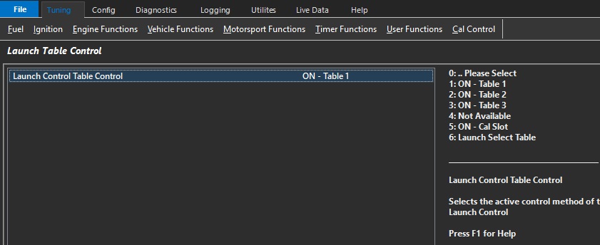
Selects the active control method of the Launch Control - 3 tables are available
0: .. Please Select
1: ON - Table 1
2: ON - Table 2
3: ON - Table 3
4: Not Available
5: ON - Cal Slot
6: Launch Select Table
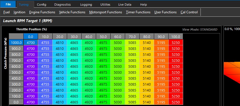
Launch RPM Table. Sets the Launch RPM when the Launch Control System is Armed.
Size: 12 x 11
Resolution: 1 RPM
Max value = 20000 RPM
Min value = 0 RPM
Ignition Retard Table. Sets the amount of Ignition Retard used when the Launch Control System is Armed.
Size: 12 x 11
Resolution: 0.5 Deg
Max value = -100.0 Deg/%
Min value = 0 Deg/%
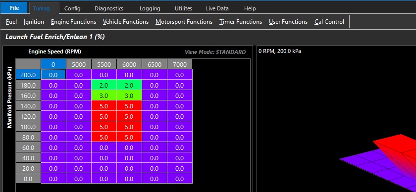
Fuel Enrich/Enlean Table. Sets the amount of Fuel Enrichment/Enleanment used when the Launch Control System is Armed.
Size: 12 x 11
Resolution: 1%
Max value = +100%
Min value = -100%
PID Based Launch Control
PID Based Launch Control:
The Emtron PID based Launch Control will apply gains in the static mode function only, as the PID target is the Launch RPM.
** RPM Control is the only PID base
This means in “Moving” mode, the ECU will follow Engine reduction calculates via the Torque Reduction Ignition, Torque Reduction Cut, and Throttle Area Demand
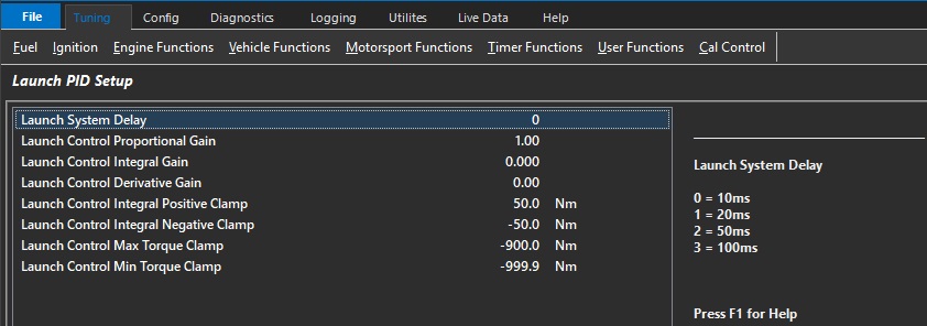
Launch PID Setup
Launch System Delay
This setting delays the routine to allow the closed loop system to function, as the torque is calculated.
0 = 10ms
1 = 20ms
2 = 50ms
3 = 100ms
Typical setting for Ignition Based PID - "2"

Typical setting for Throttle Based PID - "1"
Launch Control Proportional Gain
A value of 1.00 will output +/- 10Nm for every 100 RPM of Target error.
Typical setting for Ignition Based PID - "3"

Typical setting for Throttle Based PID - "0.5"
** Throttle Based PID - the least amount of error in the throttle area/TMF calculation feeds forward this PID
Launch Control Integral Gain
A value of 1.00 will output +/- 10Nm for every 100 RPM of Target error, but increment/count up to the integral gain limit
Typical setting for Ignition Based PID - "0.150"

Typical setting for Throttle Based PID - "0.050"
** Throttle Based PID - the least amount of error in the throttle area/TMF calculation feeds forward this PID
Launch Control Derivative Gain
The derivative change of the engine torque vs the target will be affected by this gain value
Typical setting for Ignition Based PID - "3"

Typical setting for Throttle Based PID - "1"
** Throttle Based PID - the least amount of error in the throttle area/TMF calculation feeds forward this PID