Lambda NB Sensor Heater Control
The Narrow Band Oxygen Sensor heater can be controlled using either switched or PWM mode. The method of control is adjusted from the Config View, Function Setup menu.
Switched Mode
- This is the most basic mode and switches the heater channel ON after the Post Start Lockout has finished. Same setup as below except Output Mode = Switched.
(This mode is not recommended)
Switched Mode (Table)
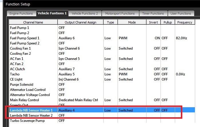
- From Config View -> Functions, select the required Channel, either Heater 1 and 2 and open.
- Select the Output Channel. In this example Sensor Heater 1 has been assigned to Auxiliary 4.
- Select Driver Type (Normally Low Side).
- Select Output Mode = Switched (Table). This puts the heater control in switched mode and allows a 3D table to control the switching conditions.
NOTE: The Output Mode set to “Switched” has the same effect as “Switched (Table)”
- Select Ok.
- The setup is complete. Now move to the tuning view.

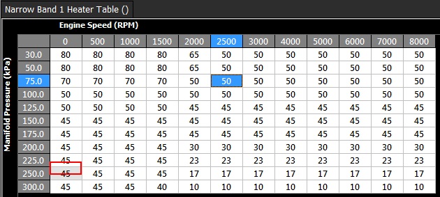
- In the tuning view select Engine Functions -> Narrow Band Heater 1 Table. This table now controls to switching of Auxiliary 4 and in turn controls the Lambda Heater.
** Important Table Rules in switched:**
Table value of 100     = Output ON

Table value of 0        = Output OFF

Any other value         = No change to the Output. This is user defined hysteresis. In the example below 50 is the value selected.
PWM Mode
- Select the required Channel, either Heater 1 and 2 then open the menu.
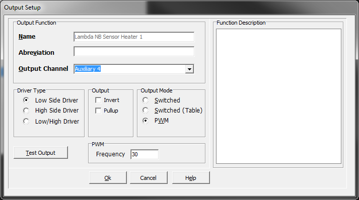
- Select the Output Channel. In this example Sensor Heater 1 has been assigned to Auxiliary 4.
- Select Driver Type (Normally Low Side).
- Select Output Mode = PWM. This puts the heater control in PWM mode and allows a 3D table to control the duty cycle.
- Select the Frequency.
- Select Ok.
- The setup is complete. Now move to the tuning view.
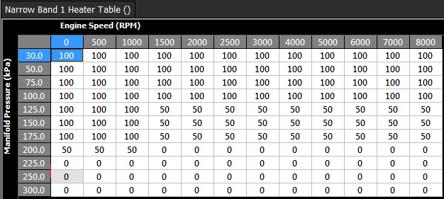
- In the tuning view select Engine Functions -> Narrow Band Heater 1 Table. This table now controls the Duty Cycle applied to Auxiliary 4 and in turn controls the Lambda Heater
** Important Table Rules in PWM mode:**
Table value of 100%     = 100% Duty Cycle

Table value of 0%    = 0% - Output is OFF

Table value of 30%    = 30% Duty Cycle