Subsections of Engine Speed Limits
Engine Speed Limit 1/2/3
Engine Speed Limits/Cuts
The following calculated runtimes are generated by Emtron that are Engine Speed Limit/Cut related (to be further discussed more specifically):
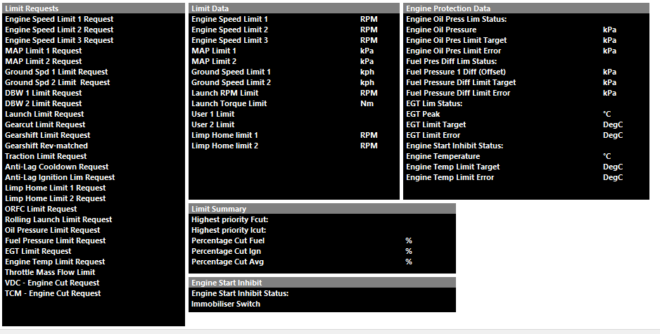
** Highest priority Fcut and Highest priority Icut Runtimes will always show the active limit request. It is highly recommended to always have these channels in the ECU logger.
The Limit with the highest percentage cut ALWAYS get priority over other pending limits. This also means any Ignition or Fuel adjustments associated with the function also get priority.
So ONLY 1 limit can be active at any one time.
Functions that can limit the engine are:
- Engine Speed Limit 1
- Engine Speed Limit 2
- Engine Speed Limit 3
- MAP Limit 1
- MAP Limit 1
- Ground Speed Limit 1
- Ground Speed Limit 2
- Launch Limit
- Gear Cut
- Traction Control Limit
- Anti-Lag Cut
- Anti-Lag cool down
- DBW Safety Limit
- Limp Home Limit 1
- Limp Home Limit 2
Example. RPM limit is currently active.
RPM LImit 1 = 60% Cut
RPM Limit 1 Ignition retard = 15 Deg
Then get a Gear Cut request is generated:
Gear Cut = 90% Cut
Gear Cut Ignition retard = 20 Deg.
The ECU will stop the RPM limit1, remove the 15 degree of retard, activate a 90% cut and apply 20 degrees retard.
RPM Limit Function Setup
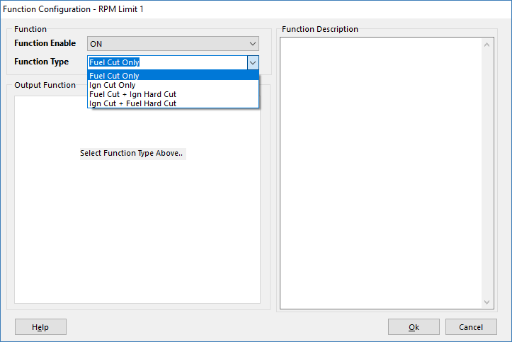
Emtron has three different RPM Limiters and four different methods for each
- Config, Function Setup, Engine Functions, RPM Limit 1/2/3
Select the cut type and order of priority for each RPM limit function
Engine Speed Limiter Setup
Engine Speed Limiter Setup
Cut Pattern
Select the cut pattern type
.
0: Random Pattern 1
1: Random Pattern 2
2: Sequential Pattern 1
3: Sequential Pattern 2
Ign Retard Mode
Applies the Ignition Retard as either an Offset or Percentage of Base Angle (Table value)
Example: Current Ignition Angle = 25.0 BTDC
Offset = 15.0 Deg Retard. Ignition Angle During
Limiting = 25.0 - 15.0 = 10.0 Deg BTDC
Percentage = 50.0 % Retard.
Ignition Base Angle = 20.0 Deg.
Ignition Angle During Limiting = 20 - 50% x 20.0 = 10.0 Deg BTDC
(assuming no other Ignition trims)
Control Range
Control Range (-/+) RPM Units
The Control Range applies to the Min/Max % Cut values
Example :
Min % Cut Clamp 10%
Max % Cut Clamp 90%
Control Range -200rpm
RPM Limit 7000rpm
At 6800rpm the engine will begin its cut routine at the Min % Cut Clamp of 10%
At 7000rpm the engine will finish its cut routine at the Max % Cut Clamp of 90%
Minimum %Cut Clamp
Percentage cut applied to the engine at the start of the control range.
Maximum %Cut Clamp
Percentage cut applied to the engine at the end of the control range.
NOTE: Maximum Cut MUST be > Minimum Cut
Hard Limit Adder
Used in Limit types 2 and 3.
Added to the start on the limit and determines the point at which a 100% cut will be applied.
Example:
Limit Type = 2 (Fuel Cut + Ign Hard Cut)
RPM Limit = 7000
Control Range = -200 RPM
Hard Limit Adder = 180 RPM
Fuel %cut Engine Limiting starts at 6800 at the Minimum %Cut
Fuel %cut Engine Limiting ends at 7000 at the Maximum %Cut
Ign 100% cut occurs at 6980 RPM and above.
dRPM Gain
Compensates for a fast rate of change in engine speed by reducing the limit value.
Used to prevent the engine pushing through the limit.
Locked out when dRPM < 2000 RPM/sec.
A Gain of 100 will reduce the limit by 100 RPM for every dRPM 1000 RPM/sec over the 2000 start threshold.
Example 1:
dRPM Gain = 100
RPM limit = 6500
dRPM = 3000 RPM/sec
New RPM Limit = 6500 - 100 = 6400
Example 2:
dRPM Gain = 100
RPM limit = 6500
dRPM = 4000 RPM/sec
New RPM Limit = 6500 - 200 = 6300
0 = OFF
Ignition Retard
The amount of Ignition Retard applied during limiting.
There are 2 modes :
Offset (Deg)
Percentage (%)
Post Start Lockout
Will prevent the limit operating during crank and for a time after the engine has started.
Useful when channels like oil pressure are assigned to an RPM limiter function.
** Using the Engine Protection Control function is highly recommended instead
RPM Limit - Turn ON Delay Table
RPM Limit - Turn ON Delay Table
Table in which you can set the delay for the RPM limit
Units in Seconds
RPM Limit - User 1/2 Offset Table
RPM Limit - User 1/2 Offset Table
Table in which you can offset the main RPM limit table +/-15000 RPM.
Span this table using any Emtron calculated runtime like Rotary Position, Race Timer, User Timer, etc.
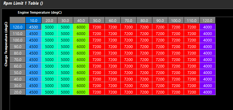
RPM Limit Table
RPM Limit Table