Hints & Tips
ECU Overview/Pinout
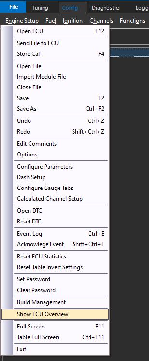
The cal file information such as pin configuration, assignments, and even the FW version can easily be accessed via the file menu under “Show ECU Overview”
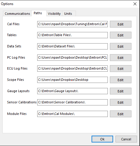
Setting Paths
Paths can be reset under the file menu under “Options”.
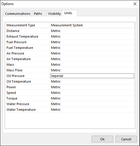
Unit Preferences
Units can be converted under the file menu under “Options”.
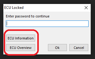
ECU Cal FIle Locking
ECU Cal Files can be locked under the file menu (Password protection).
CautionThe ECU cal file cannot be unlocked by Emtron Support for any reason if it is locked, as this is done in the actual calibration file.The user is free to load in any cal file they please though, including an unlocked cal file (on top of a locked cal file).
Loading in a new cal file will overwrite the cal file loaded into the ECU, so that current cal file will be lost.
If a cal file is locked, Emtune will allow the user to view the “ECU Overview” though to see what the current pinout of the ECU is.
Viewing Runtimes
Pressing “F3” anytime the ECU is open will display all calculated channels in real time. Navigate through the tabs, or “Search” for the channel you are looking to view.
Output Testing
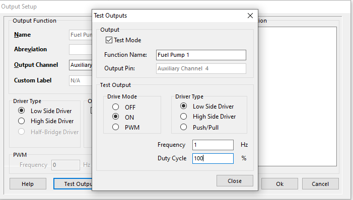
All outputs can be tested in the ECU, and this is a recommended procedure before running the engine and crucial components for the first time.
Outputs controlled by functions, can be tested right from the function output setup. The “Test Output” button brings you to this section, where you can set conditions for the output test :
To test fuel and ignition channels, this is done under Config Fuel/Ignition > Injector/Ignition Test
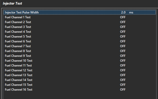
Set the pulse width/dwell for the test, and then turn the channels on to test.
CautionDo not test channels with the engine runningNote: The channels are the actual channel assignments from the ECU, and not the cylinder assignments - IE if you have cylinders assigned on different channels, they will NOT correspond during this test.
Starting Engine/No Start
Once configuration is complete, startability of the engine can be observed (and logged) in Runtimes view (F3) under Triggers/Limits > Engine Decoding Status.
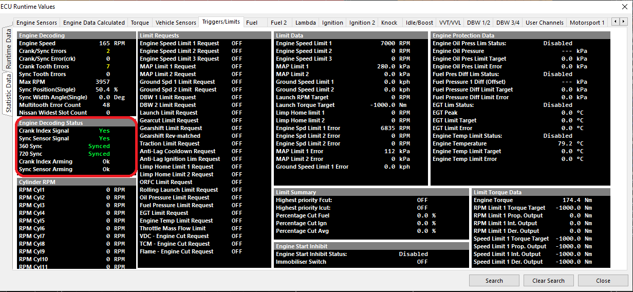
For sequential configuration, Crank, Sync, 360, and 720 sync must all go “Green” in order for the decoding to be satisfied and the engine startability to be achieved.
Tip Engine Speed should be observed cranking as well
On universal configurations such as “Multi-tooth Custom”, if the engine will not start, the stroke for sequential firing may be on the wrong phase.
An easy way to correct this is to add 360 degrees to the Crank Index Offset value.
Engine Limiting Active
The Emtron ECU can perform a number of different limit types. View what limiters are active in Runtime view (F3) under Triggers/Limits.
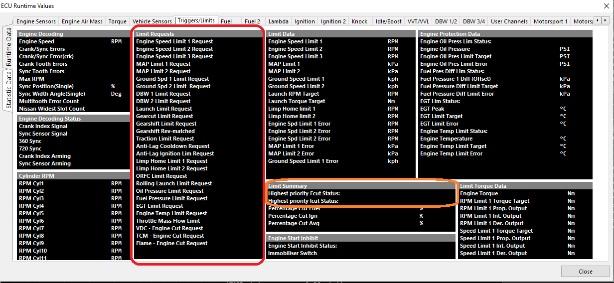
Limit Requests will show the specific limiter active
Under Limit Summary, Highest priority Fcut/Icut Status will also show the current limiter active (by priority of cut %)
Tip: Highest priority cuts are recommended to always be logged.
Trigger Errors
The following Error channels are calculated in the ECU.
Crank/Sync Errors- This is a counter that will register if the ECU sees an issue during an engine cycle where the Crank Tooth and Sync Tooth are not legitimate.Crank/Sync Errors(crk)- This error is the same as Crank/Sync Errors but occurs inside the Cranking Speed entry window (Crank RPM Entry and Crank RPM exit).Crank Tooth Errors- This is a counter that will register if the ECU sees the incorrect number of expected count of crank teeth during an engine cycle.Sync Tooth Errors- This is a counter that will register if the ECU sees the incorrect number expected sync teeth during an engine cycle,
Data Logging/Diagnostic Tips
Crank Tooth, Crank/Sync, Crank/Sync(crk) counting during engine cranking/low battery voltage sometimes can be considered normal depending on the trigger type, tooth count, engine compression ratio, etc.
This is due to the ECU attempting to scrutinize the trigger accurately during cranking, missing teeth, crank index teeth, etc.
Crank Tooth Errorsalone usually mean the main Crank Index Signal has issuesCrank/Sync Errorsalone usually mean there is a Sync Sensor Signal issue.Crank Tooth ErrorsANDCrank/Sync Errorsusually mean there is interference/rouge on one or both of the main trigger inputs. Investigate the Sync Signal first with the ECU Scope.
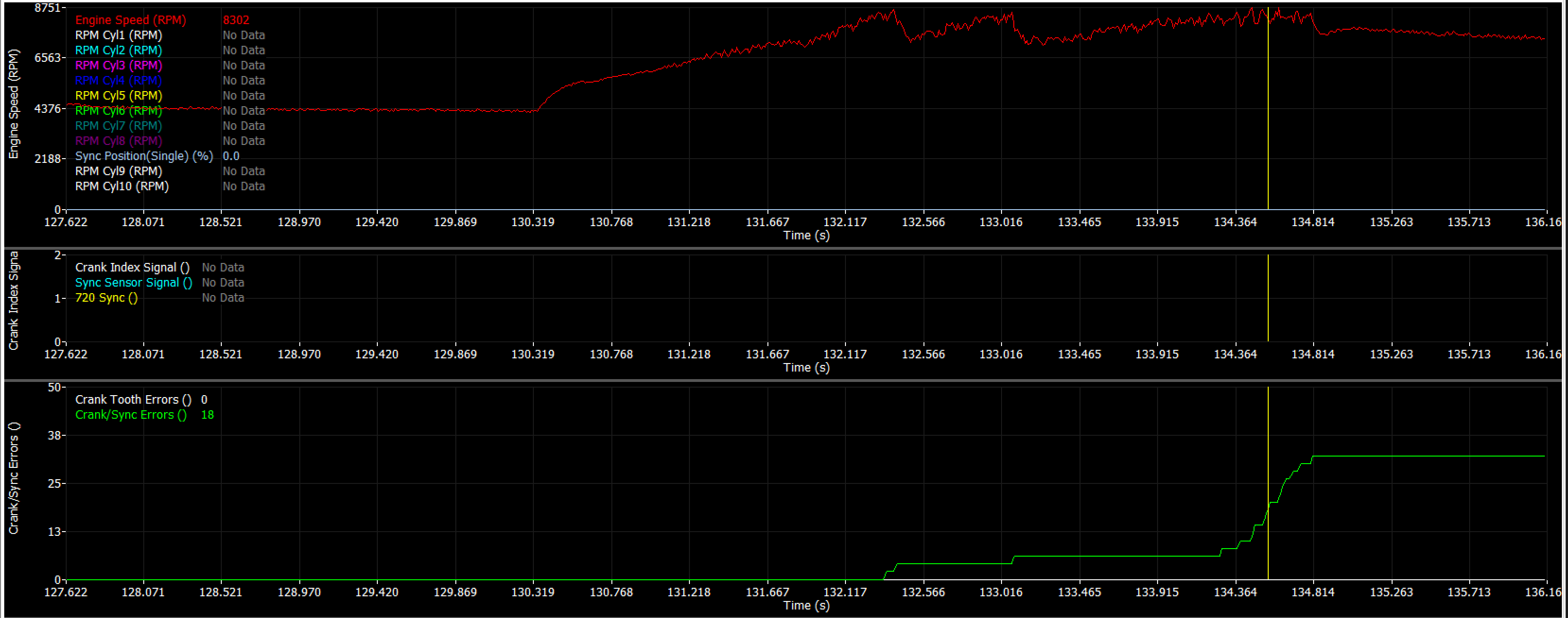
Example of vehicle with failing Sync sensor signal.
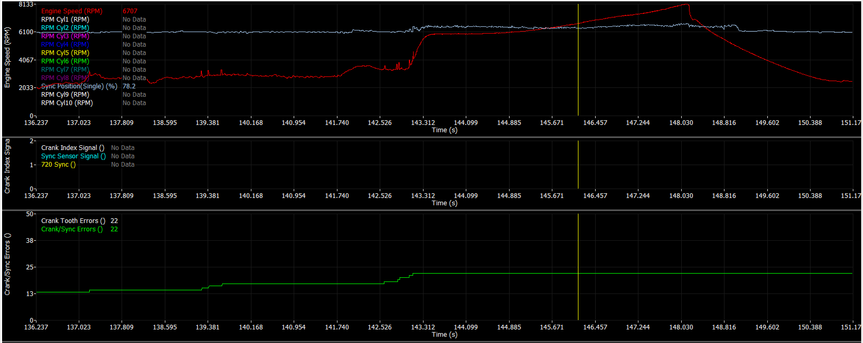
Example of vehicle with rouge sync sensor signals (triggering both crank and crank/sync tooth errors together).