Subsections of Getting Started
First Time Use
If using the ECU for the first time
- Download software - EmNet
- Obtain a Tuning Cable
- Set up Ethernet port - Ethernet Setup Guide. Emtune software will communicate to the ECU over a static IP address which must be configured.
- Read the KV Series Hardware Manual
- Read the particular ECU Data sheet
- Familiarise your self with the Emtron EFI relay control & power distribution
- Read the help, familiarize yourself with the software and don’t be afraid to ask for assistance if you get stuck or are unsure.
Ethernet Connection
Connecting the ECU
Communication Cable
The Emtron proprietary communication cable translates standard high speed Ethernet to a Lemo connector that feeds directly into the ECU header.
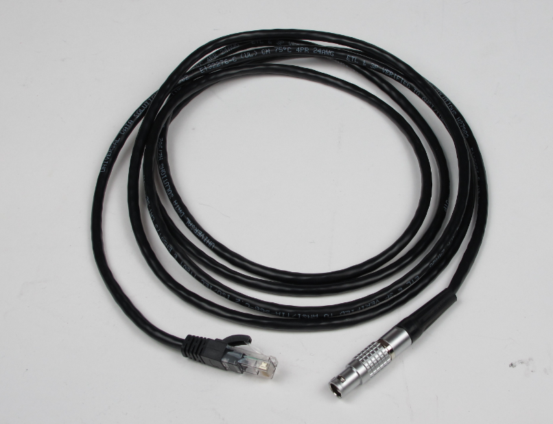
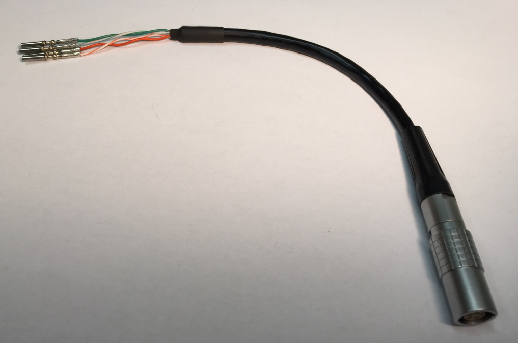
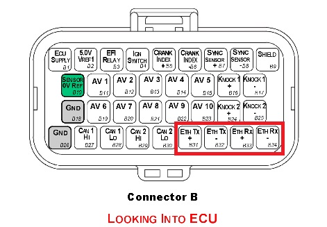
The pin configuration for the Lemo receiver is as follows.
SL series
| Wire | SL Pin |
|---|---|
| Green/White | B31 (TX+) |
| Green | B32 (TX-) |
| Orange/White | B33 (RX+) |
| Orange | B34 (RX-) |
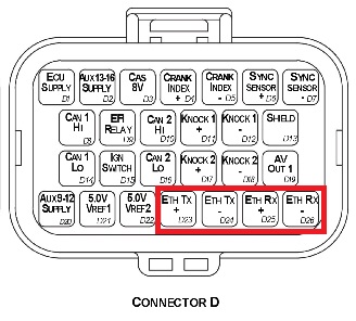
KV series
| Wire | SL Pin |
|---|---|
| Green/White | D23 (TX+) |
| Green | D24 (TX-) |
| Orange/White | D25 (RX+) |
| Orange | D26 (RX-) |
IP Config
The Emtune software will communicate to the ECU over a static IP address.
Set your IP and subnet to the following on the Ethernet port you will be using on your PC.
IP: 192.168.1.50
Subnet: 255.255.255.0
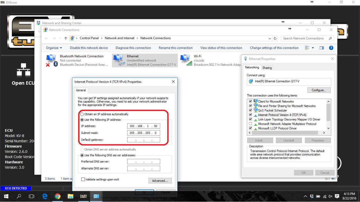
With successful connection, the Emtune Welcome screen will display “ECU DETECTED” in blue in the bottom left corner as can be observed in the background in the above example.
For detailed IP Configuration info click here: IP Configuration
Shortcut Keys
Navigation
| Key | Function |
|---|---|
| V | Toggle View between Tuning and Config |
| Esc | Toggle focus on menu bar |
| Alt + F | Open File Tab |
| F3 | Open/Close ECU runtimes |
| H | Toggle Table Description |
| [ | Scroll between views Left |
| ] | Scroll between views Right |
Table Direct Entry
| Key | Function |
|---|---|
| Pg Up | Increment value by 0.1 |
| Pg Down | Decrement value by 0.1 |
| Shift Pg Up | Increment value by 1.0 |
| Shift Pg Dn | Decrement value by 1.0 |
Table Tools
| Key | Function |
|---|---|
| F5 | Toggle Fuel and Ignition Main Table |
| F6 | Open Lambda Table |
| A | Axis Setup |
| I | Interpolate |
| Ctrl + A | Select Complete Table |
| Ctrl + C | Copy Selection |
| Shift + Crtl + C | Copy Table |
| Ctrl + V | Paste Selection |
| Shift + Ctrl +V | Paste Table |
| Ctrl + Alt + C | Save Table |
| Ctrl + Alt + V | Load Table |
| Ctrl + Alt + I | Import Table |
| Ctrl + Space Bar | Active Cell Tracking |
| Z | Restore last stored cell/s value \ |
| G | Toggle Graph |
| S | Smoothing Function |
| H | View Table Description |
| D | Display Differences from ECU last stored value |
| ; | Table Color Gradient Toggle |
| L | Auto Lambda Correction |
| M | Manual Entry Lambda Correction |
| Y | Invert Y-Axis |
| O | Toggle Logger Position (Yellow Box) |
| Q | Copy programmable Live Runtime into active cell |
File Management
| Key | Function |
|---|---|
| F2 | Save File |
| Crtl + F2 | Save As |
| Crtl + Z | Undo Last Change |
| Shift + Crtl + Z | Redo Last Change |
Logging
| Key | Function |
|---|---|
| F8 | Start/Stop Logging |
| F9 | Pause Logging |
| F7 | Open Manage Log Files Window |
| O | Toggle Overlay |
| Y | Overlay Offset Left |
| Crtl+Y | Overlay Offset Left Fast |
| I | Overlay Offset Right |
| Crtl+I | Overlay Offset Right Fast |
| U | Set Overlay Offset |
| W | Zoom Reset |
| D | Dual Cursor Mode |
| S | Swap Active Cursor |
| B | Bring Cursors Together |
Display Settings
| Key | Function |
|---|---|
| F11 | Maximize View Area |
| Crtl+F11 | Table Full screen |
Hints & Tips
ECU Overview/Pinout
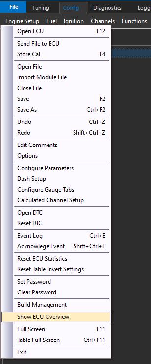
The cal file information such as pin configuration, assignments, and even the FW version can easily be accessed via the file menu under “Show ECU Overview”
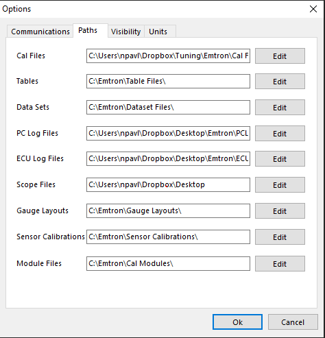
Setting Paths
Paths can be reset under the file menu under “Options”.
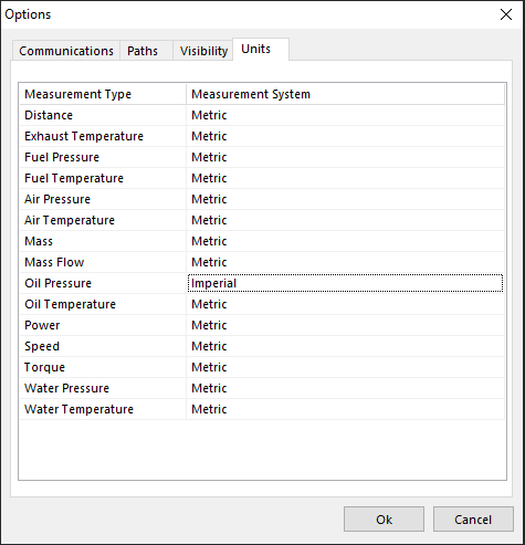
Unit Preferences
Units can be converted under the file menu under “Options”.
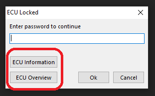
ECU Cal FIle Locking
ECU Cal Files can be locked under the file menu (Password protection).
CautionThe ECU cal file cannot be unlocked by Emtron Support for any reason if it is locked, as this is done in the actual calibration file.The user is free to load in any cal file they please though, including an unlocked cal file (on top of a locked cal file).
Loading in a new cal file will overwrite the cal file loaded into the ECU, so that current cal file will be lost.
If a cal file is locked, Emtune will allow the user to view the “ECU Overview” though to see what the current pinout of the ECU is.
Viewing Runtimes
Pressing “F3” anytime the ECU is open will display all calculated channels in real time. Navigate through the tabs, or “Search” for the channel you are looking to view.
Output Testing
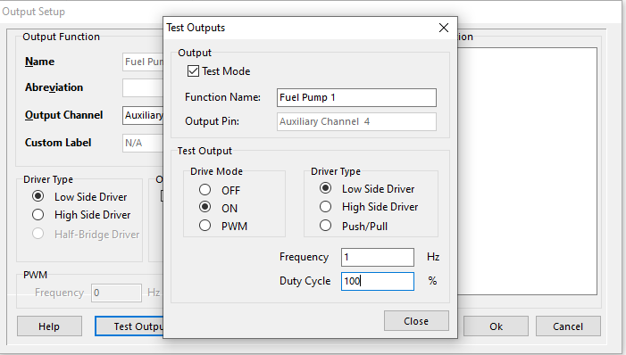
All outputs can be tested in the ECU, and this is a recommended procedure before running the engine and crucial components for the first time.
Outputs controlled by functions, can be tested right from the function output setup. The “Test Output” button brings you to this section, where you can set conditions for the output test :
To test fuel and ignition channels, this is done under Config Fuel/Ignition > Injector/Ignition Test
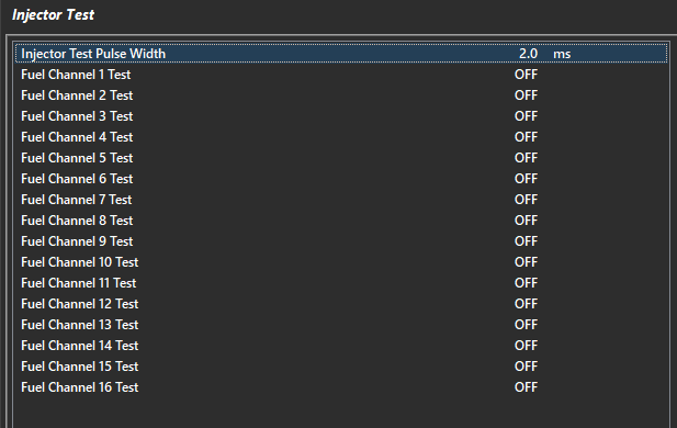
Set the pulse width/dwell for the test, and then turn the channels on to test.
CautionDo not test channels with the engine runningNote: The channels are the actual channel assignments from the ECU, and not the cylinder assignments - IE if you have cylinders assigned on different channels, they will NOT correspond during this test.
Starting Engine/No Start
Once configuration is complete, startability of the engine can be observed (and logged) in Runtimes view (F3) under Triggers/Limits > Engine Decoding Status.
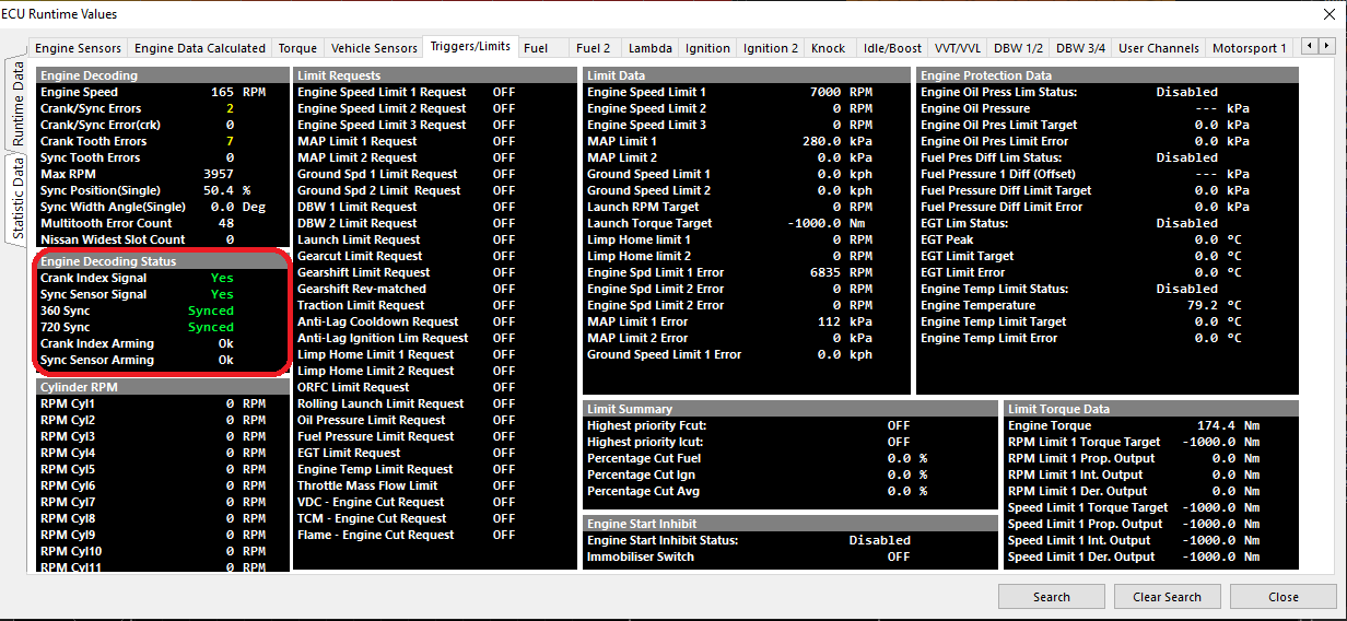
For sequential configuration, Crank, Sync, 360, and 720 sync must all go “Green” in order for the decoding to be satisfied and the engine startability to be achieved.
Tip Engine Speed should be observed cranking as well
On universal configurations such as “Multi-tooth Custom”, if the engine will not start, the stroke for sequential firing may be on the wrong phase.
An easy way to correct this is to add 360 degrees to the Crank Index Offset value.
Engine Limiting Active
The Emtron ECU can perform a number of different limit types. View what limiters are active in Runtime view (F3) under Triggers/Limits.

Limit Requests will show the specific limiter active
Under Limit Summary, Highest priority Fcut/Icut Status will also show the current limiter active (by priority of cut %)
Tip: Highest priority cuts are recommended to always be logged.
Trigger Errors
The following Error channels are calculated in the ECU.
Crank/Sync Errors- This is a counter that will register if the ECU sees an issue during an engine cycle where the Crank Tooth and Sync Tooth are not legitimate.Crank/Sync Errors(crk)- This error is the same as Crank/Sync Errors but occurs inside the Cranking Speed entry window (Crank RPM Entry and Crank RPM exit).Crank Tooth Errors- This is a counter that will register if the ECU sees the incorrect number of expected count of crank teeth during an engine cycle.Sync Tooth Errors- This is a counter that will register if the ECU sees the incorrect number expected sync teeth during an engine cycle,
Data Logging/Diagnostic Tips
Crank Tooth, Crank/Sync, Crank/Sync(crk) counting during engine cranking/low battery voltage sometimes can be considered normal depending on the trigger type, tooth count, engine compression ratio, etc.
This is due to the ECU attempting to scrutinize the trigger accurately during cranking, missing teeth, crank index teeth, etc.
Crank Tooth Errorsalone usually mean the main Crank Index Signal has issuesCrank/Sync Errorsalone usually mean there is a Sync Sensor Signal issue.Crank Tooth ErrorsANDCrank/Sync Errorsusually mean there is interference/rouge on one or both of the main trigger inputs. Investigate the Sync Signal first with the ECU Scope.
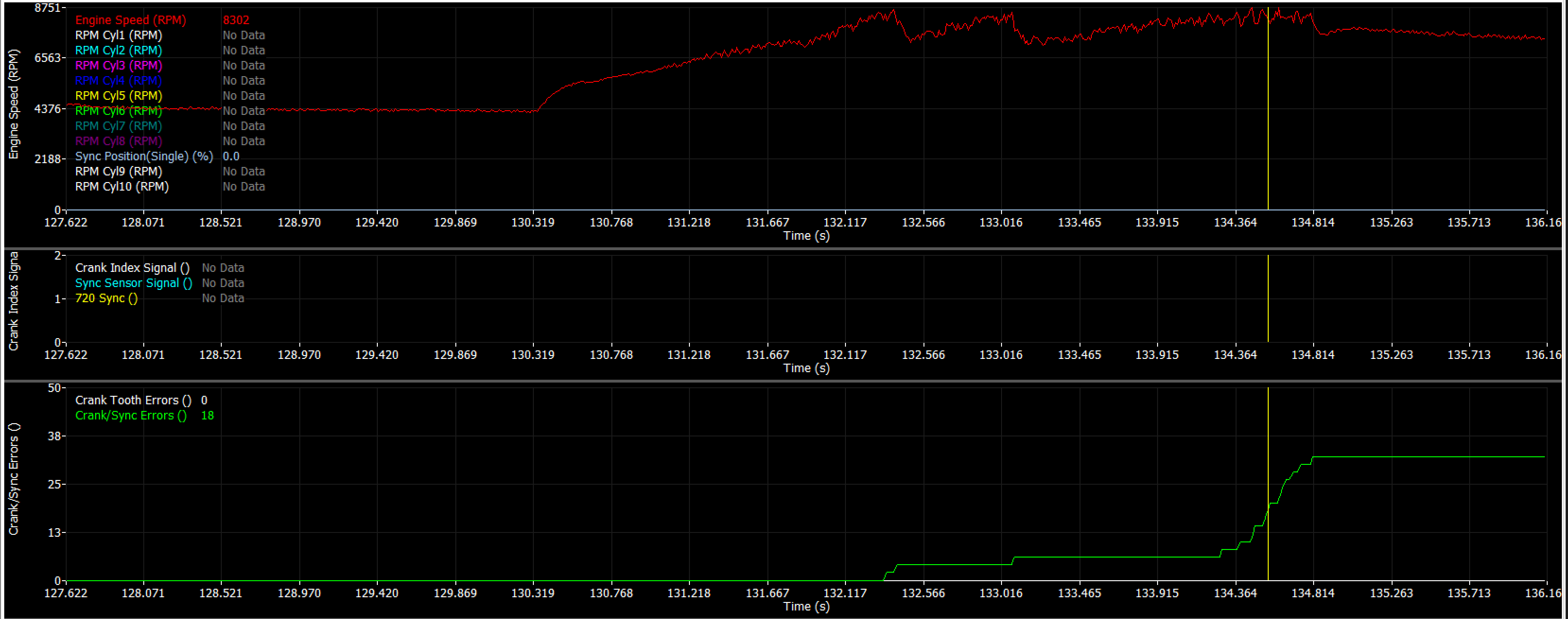
Example of vehicle with failing Sync sensor signal.
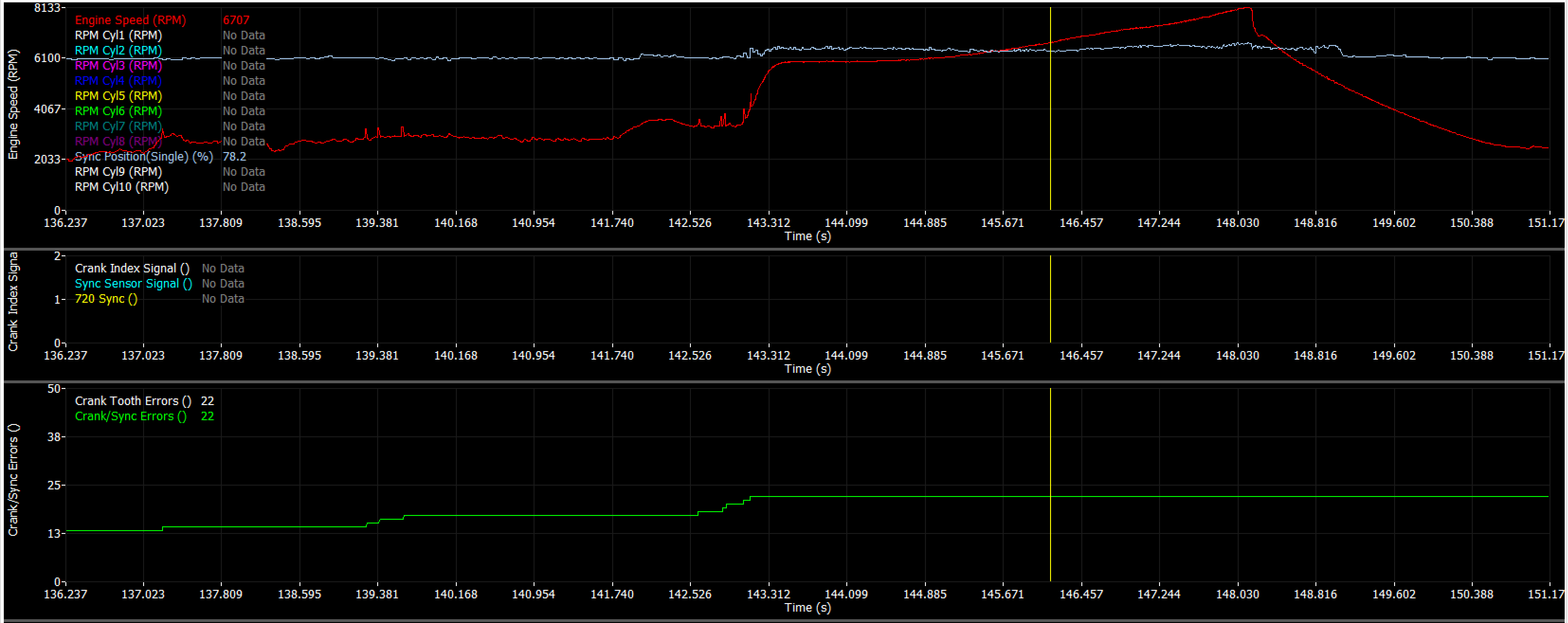
Example of vehicle with rouge sync sensor signals (triggering both crank and crank/sync tooth errors together).
Support
What is included, and what kind of support should be expected from Emtron?
Emtron provides worldwide technical support to our dealers and customers, with support staff located around the globe for fast response regardless of your time zone. Our team includes expert calibrators, who have worked on countless applications and engine configurations, and have a comprehensive understanding of the Emtron hardware and software product line to help answer your questions and troubleshoot issues.
While our support staff are absolutely here to answer questions, support hardware issues, and help point you in the right direction - for a wide variety of reasons, unfortunately our staff cannot tune customer vehicles, provide more than basic base/start up maps, or teach fundamentals of engine tuning or even basic fundamentals of the software. Emtron software and hardware is incredibly capable and sophisticated, but deserves some dedication and time to learn and understand full functionality.
Emtron support is here to guide experienced tuners in the use of the hardware and software, as well as to ensure there are no problems with the hardware or software. Emtron provides training sessions around the world annually and we encourage all dealers and self-tuning end-customers to sign up for these events. In addition Emtron recommends EFI University’s series of classes particularly those focused on the use of Emtune software. Furthermore, Emtron’s dealer network consists of some of the best tuners in the world - for end-customers seeking one-on-one support and training in the product, we strongly suggest you contact Emtron dealers in your geography to see how they can help you achieve your goals.
How to contact support?
All support requests are fed into a ticket system, and requests should be made simply by emailing support@emtronaustralia.com.au
Phone Support
Australia: +61 9679 8979
USA: +1978 364 3510
What to include in your support requests
Cal File and Logs: 9 out of 10 times, support staff will need to review the working calibration file and any log file of the conditions in question.
PC logging is the best way to capture the log, as it will record all channels for the staff to review.
Locked Cal Files
If calibration files are locked, our support staff will NOT be able to unlock them. Please provide the password for the cal file in the request, or send unlocked versions of the cal file.
Our support staff do not further record, database, or share any users cal files, passwords, etc.