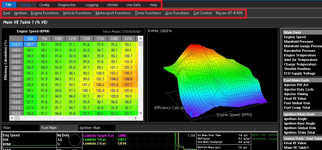
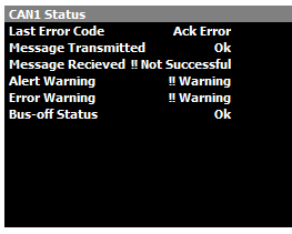
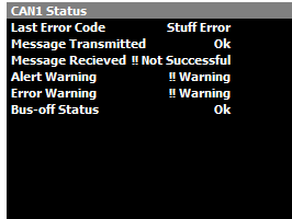
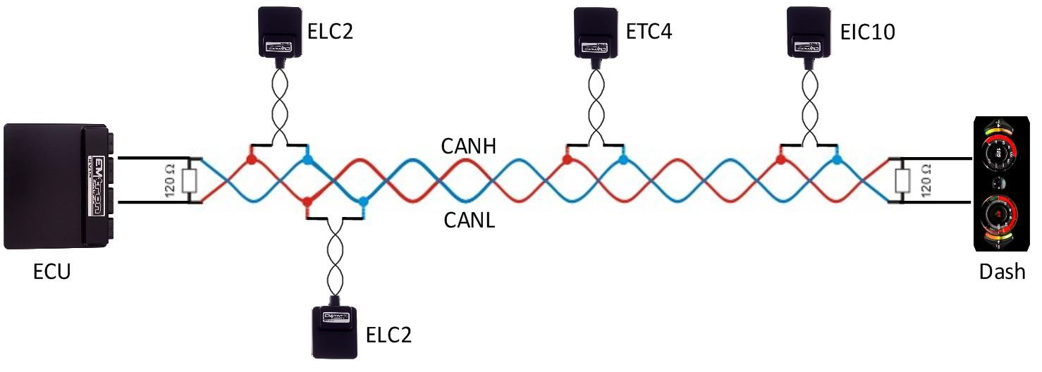
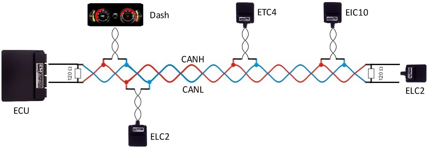
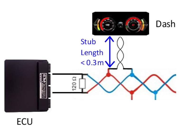
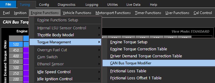
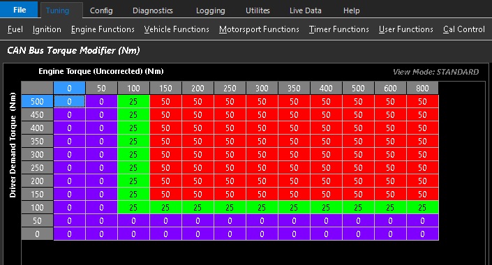
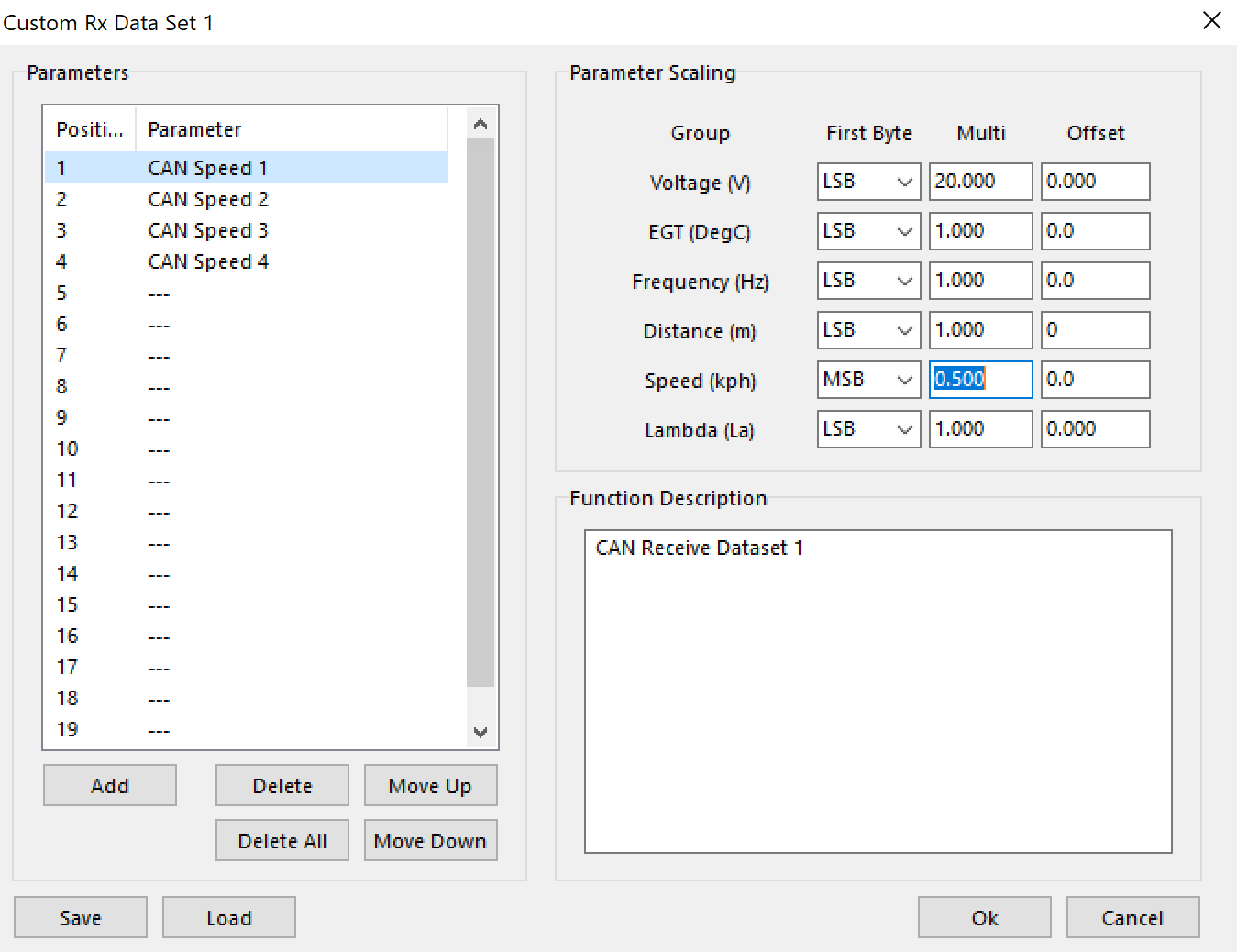
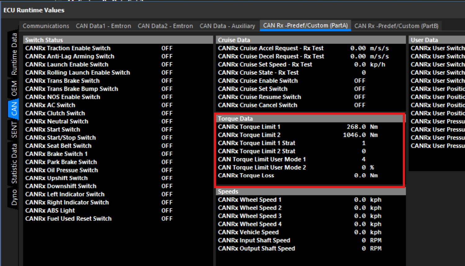
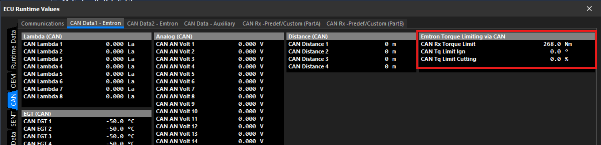
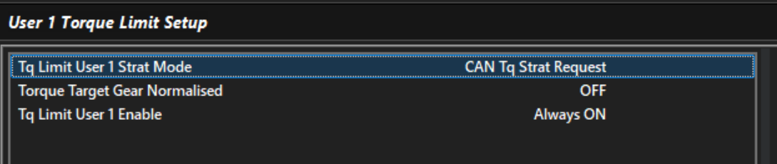
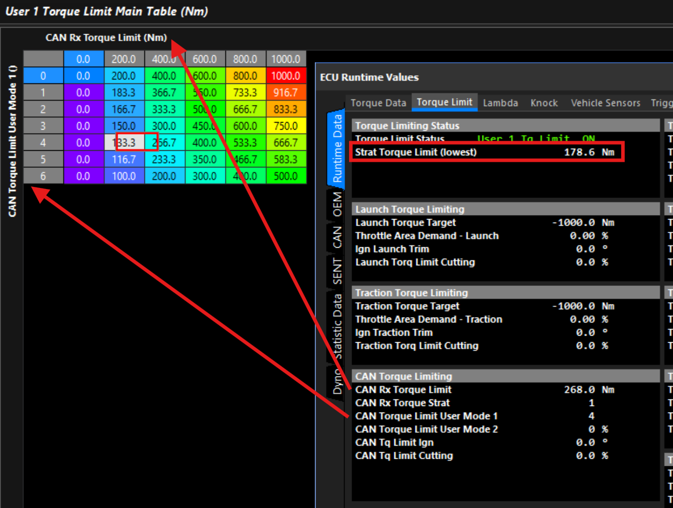
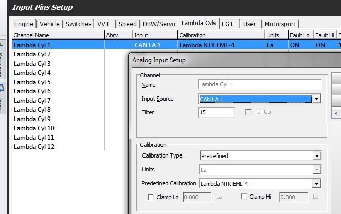
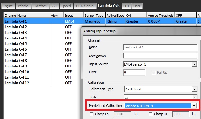
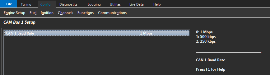
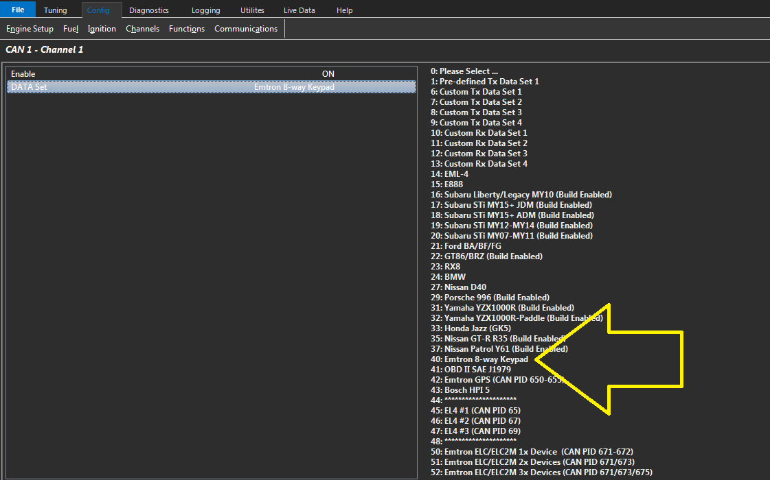
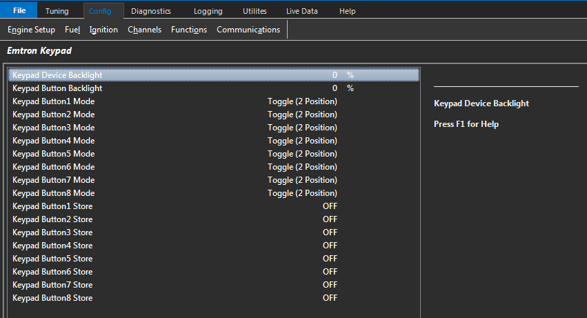
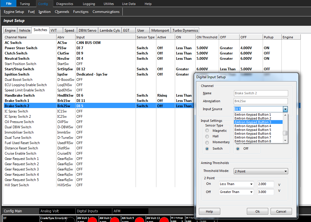
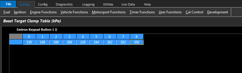
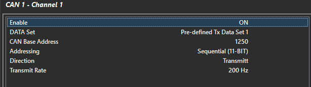
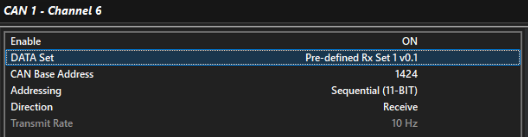
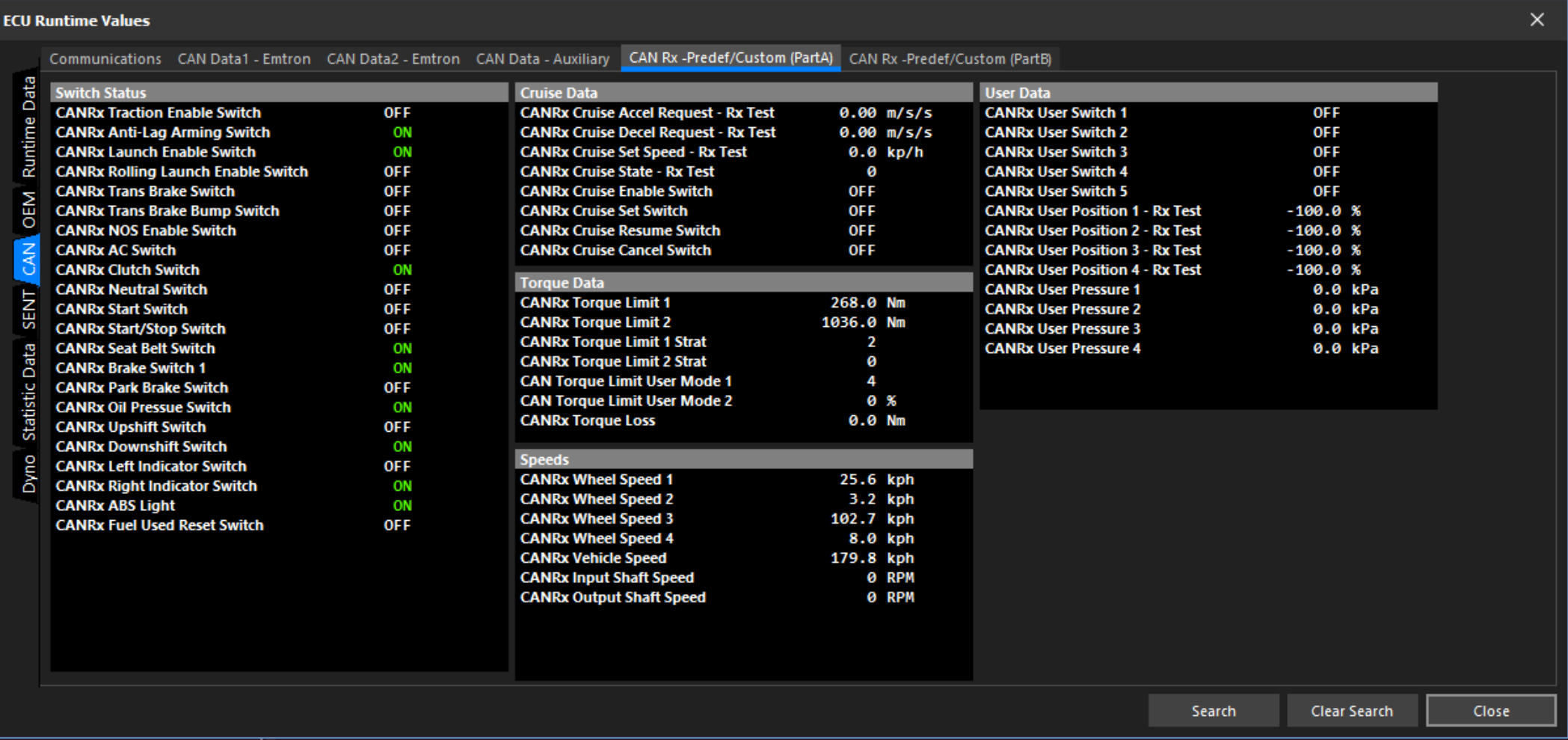
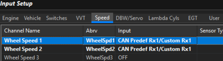
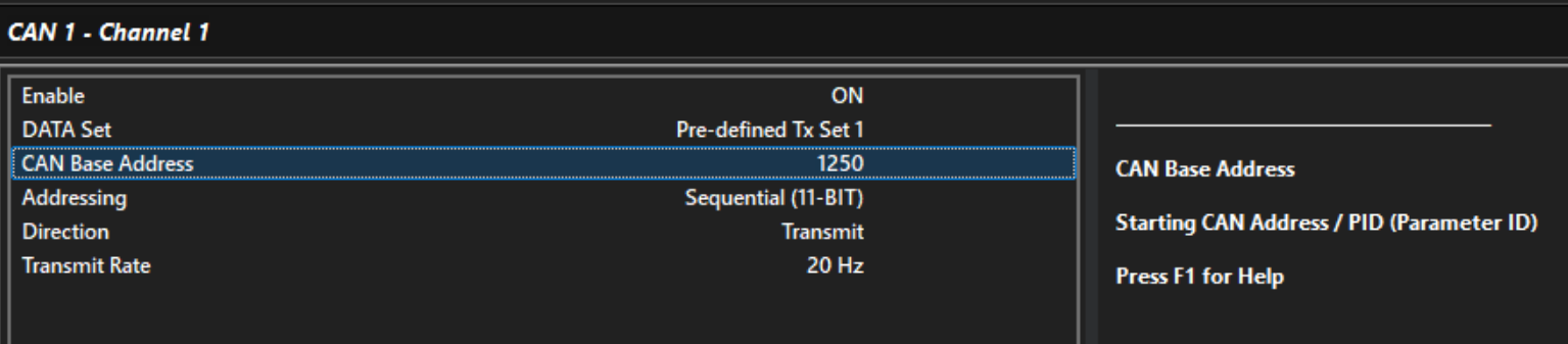
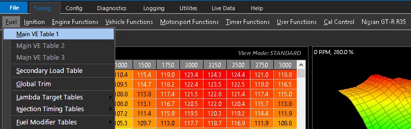
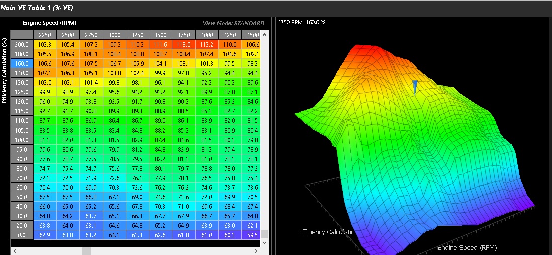
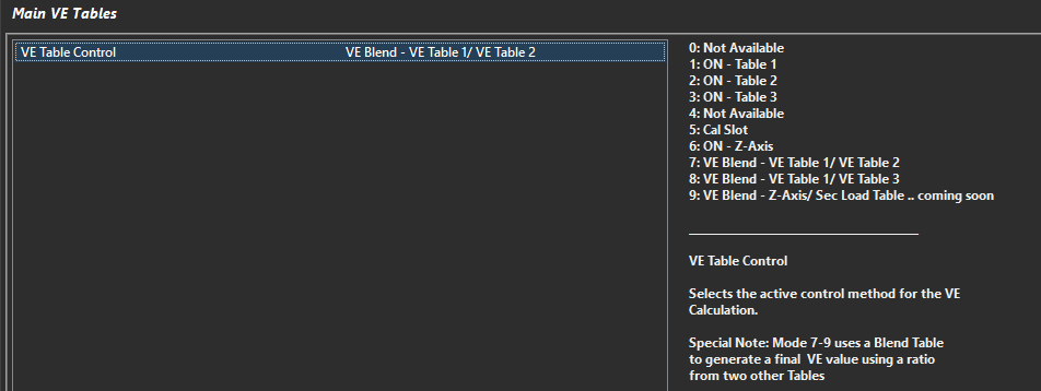
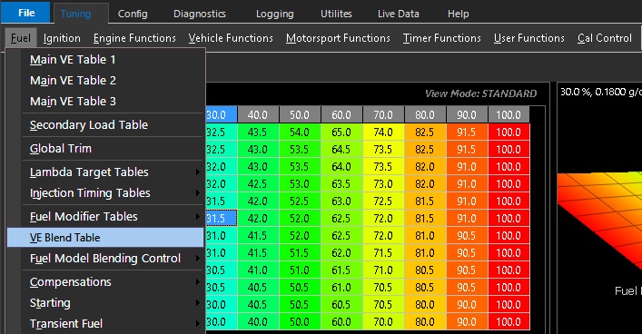
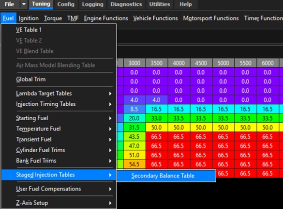
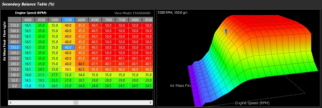
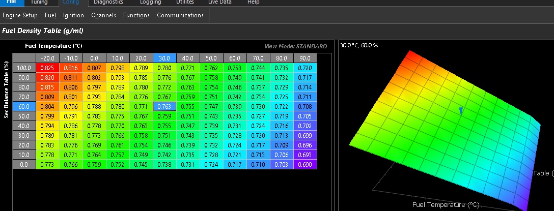
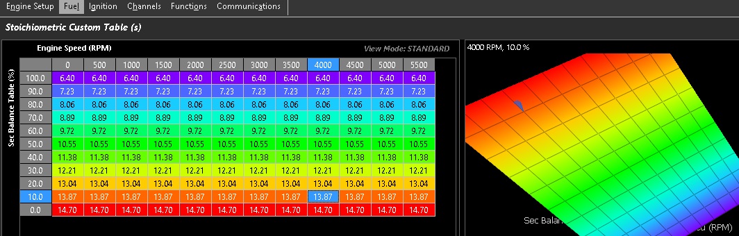
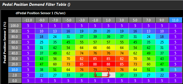
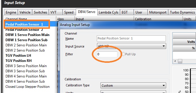
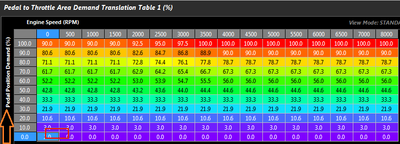
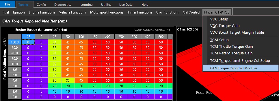
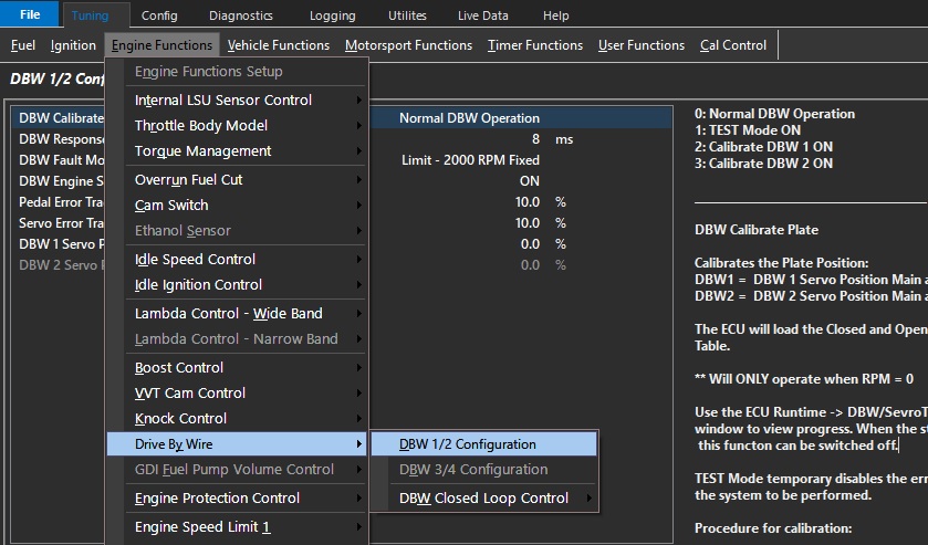
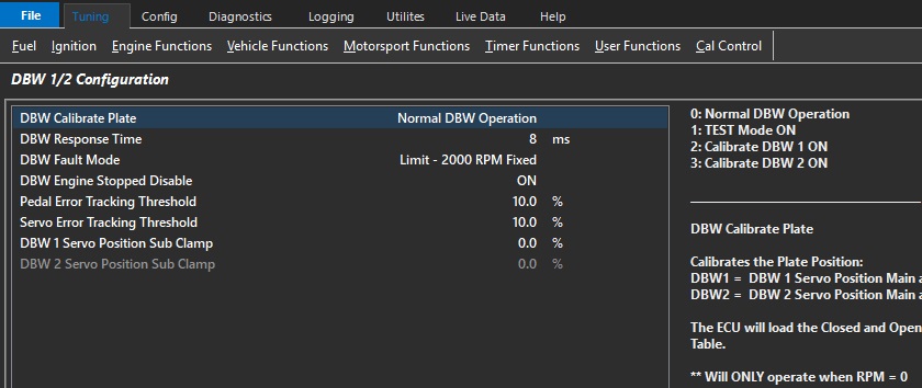
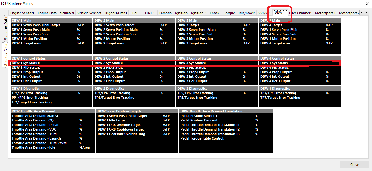
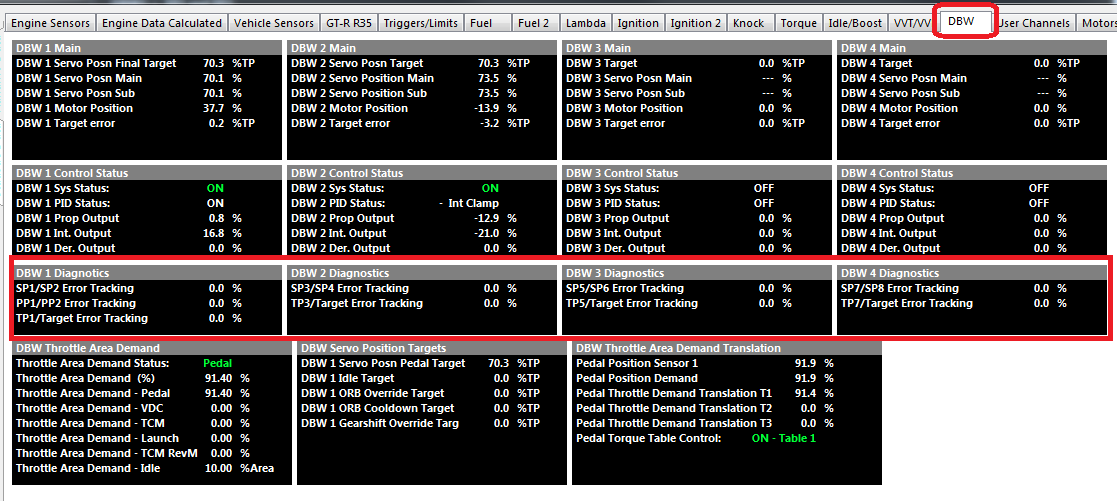
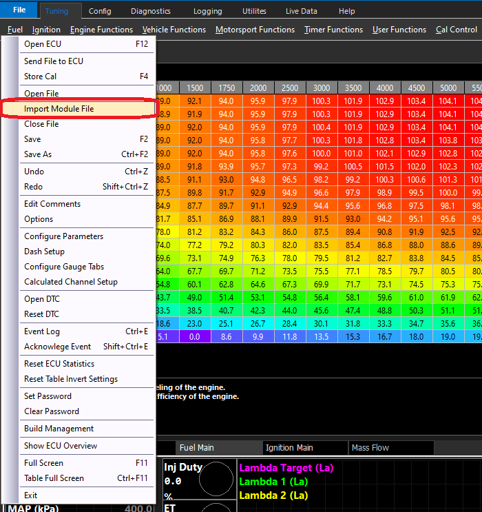
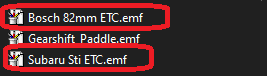
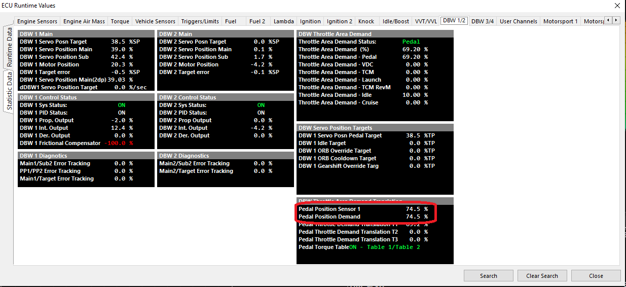
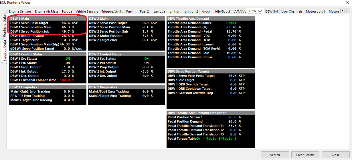
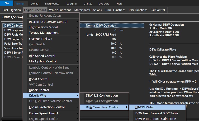
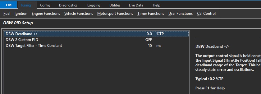
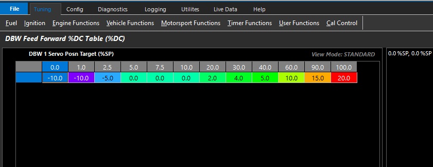
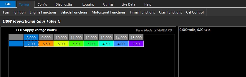
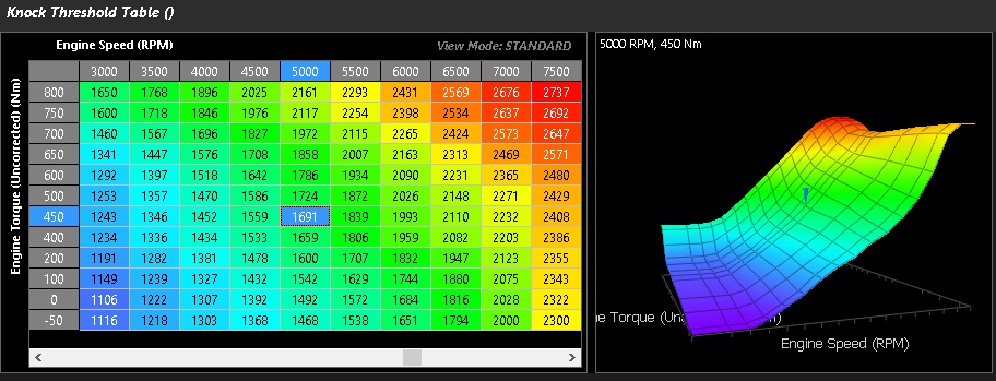
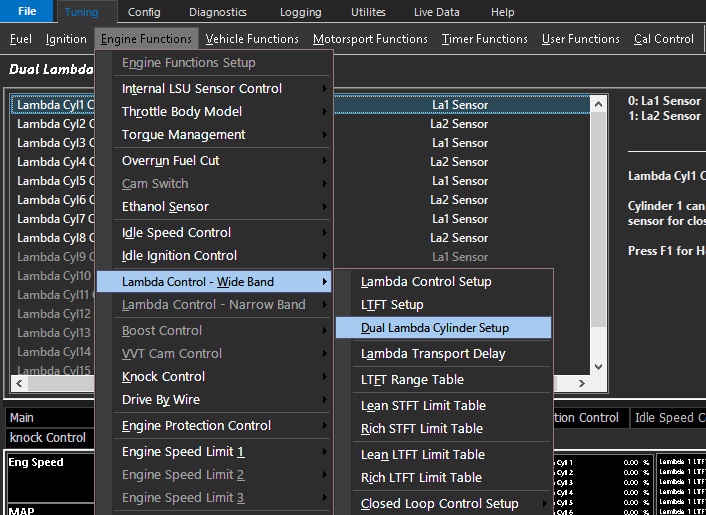
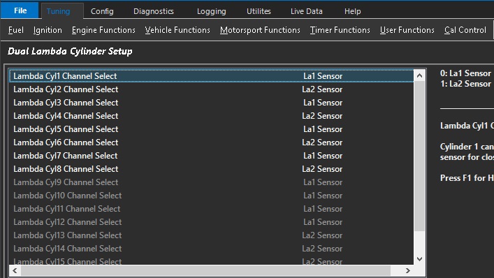
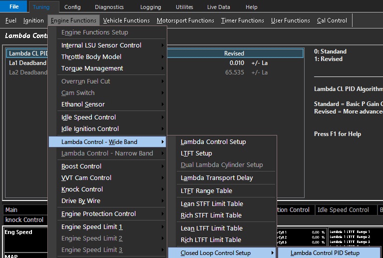
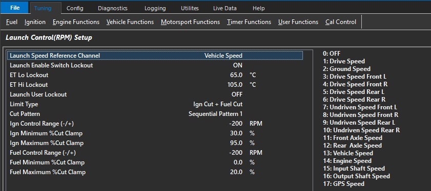
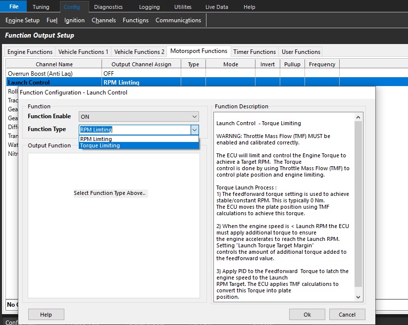
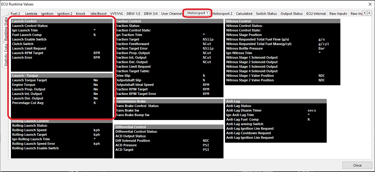
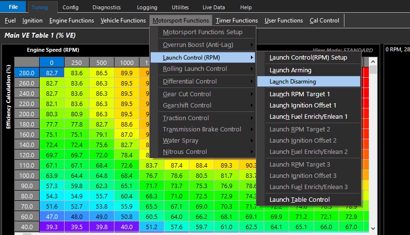
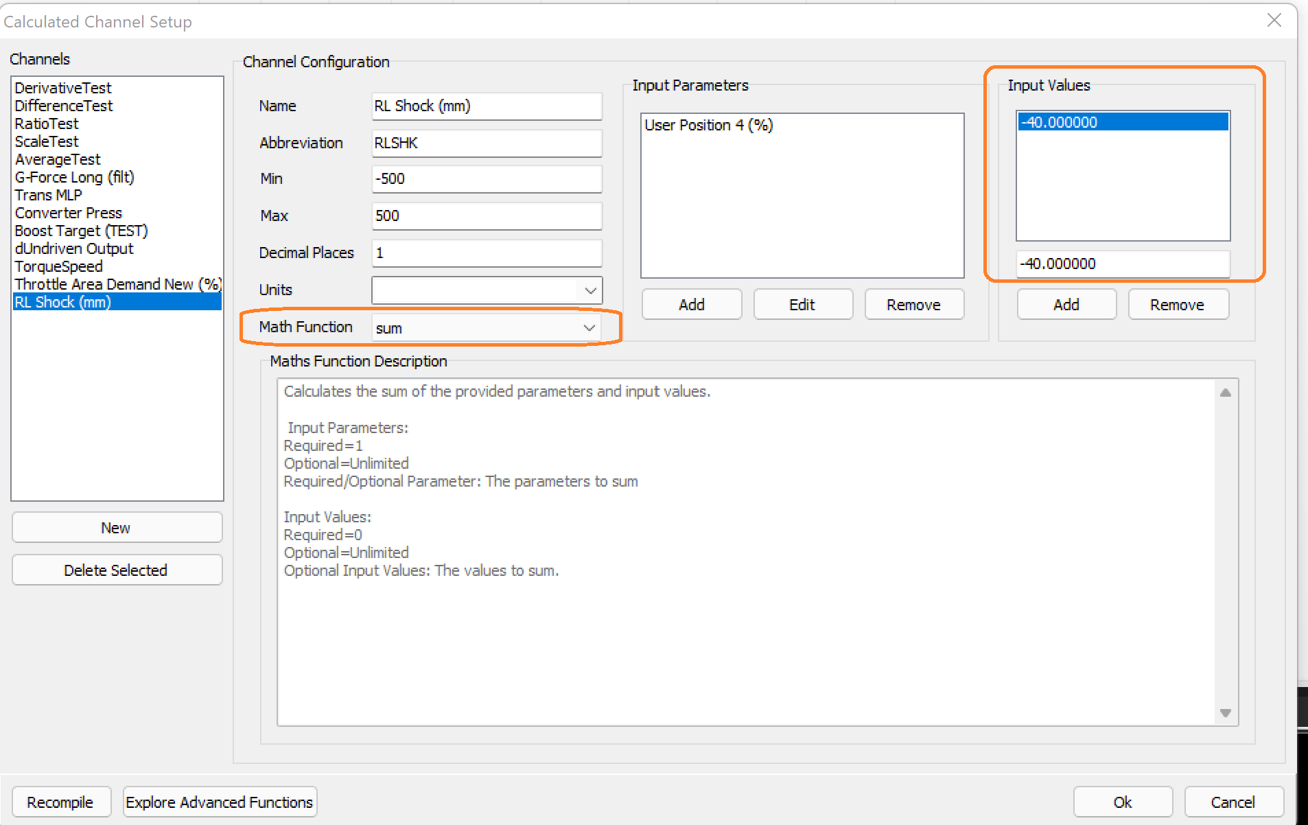
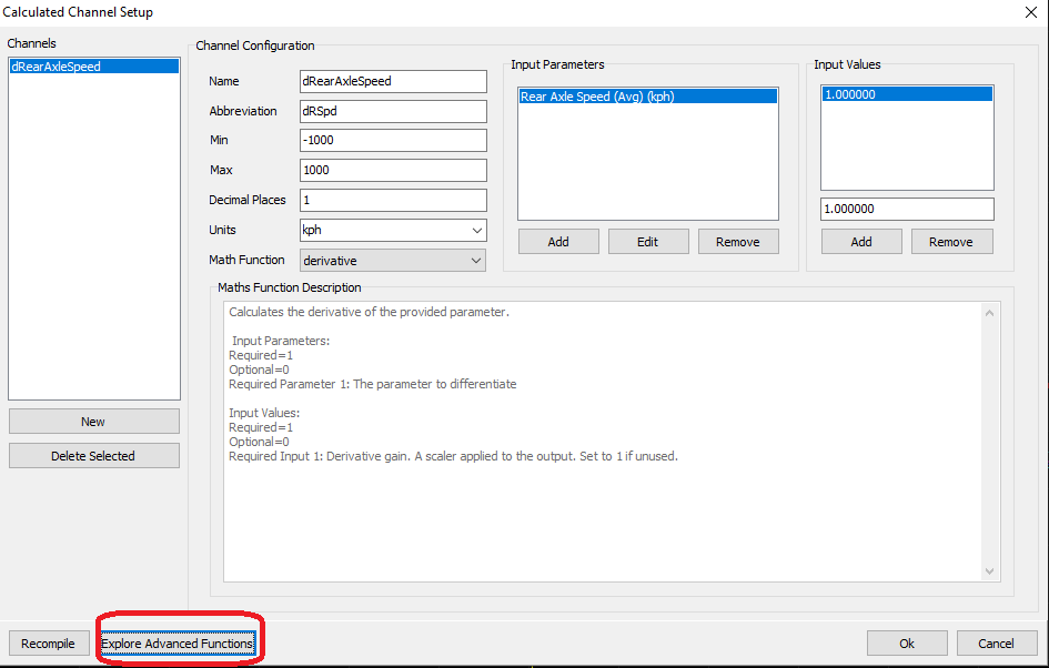
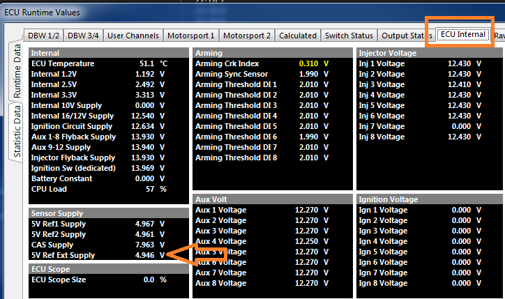
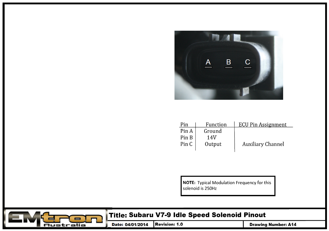
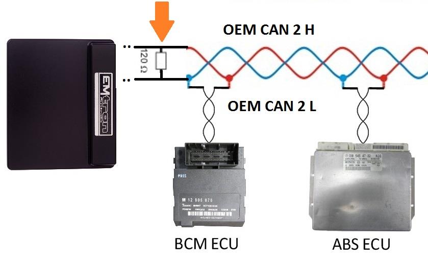
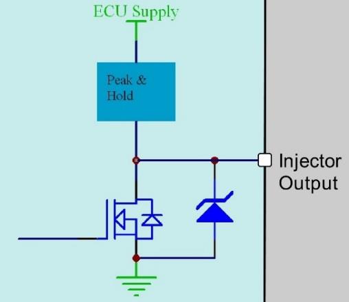
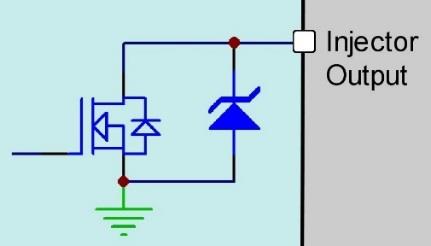
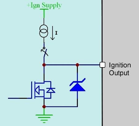
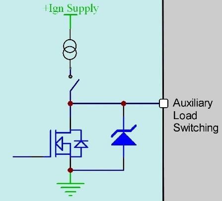
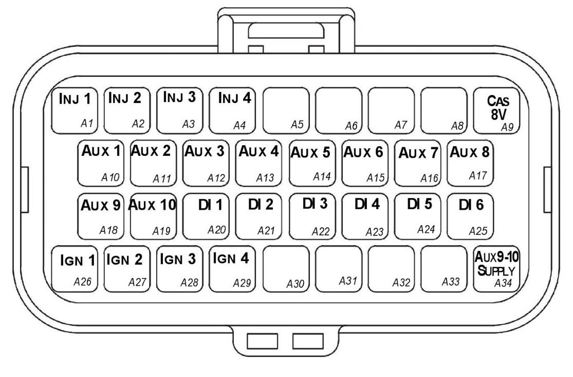
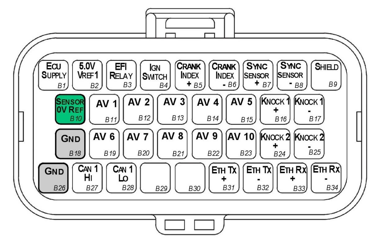
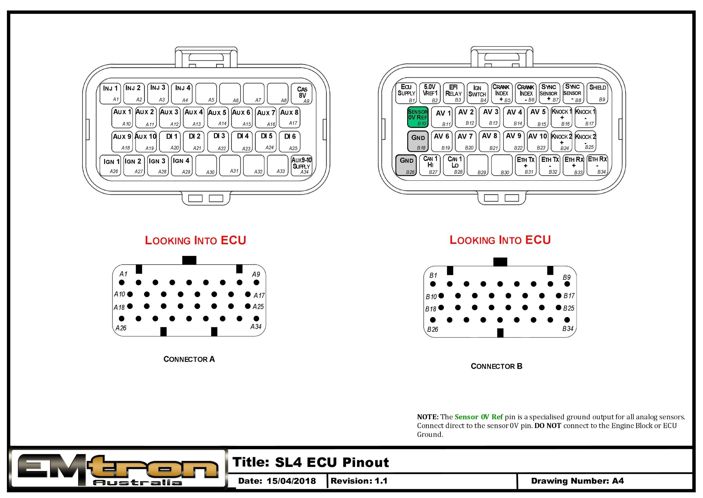
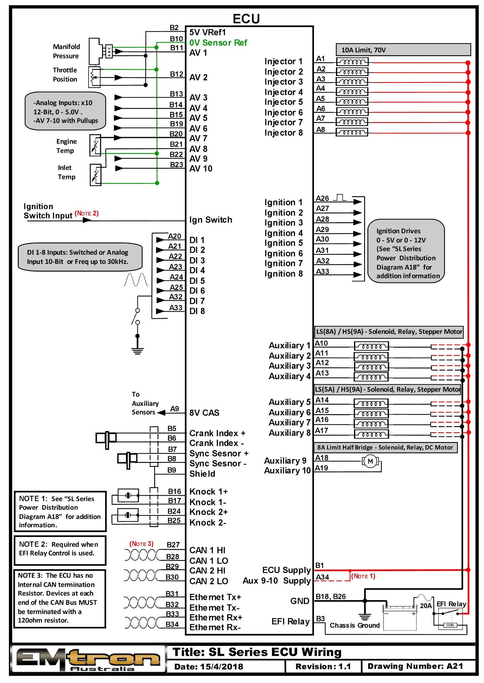
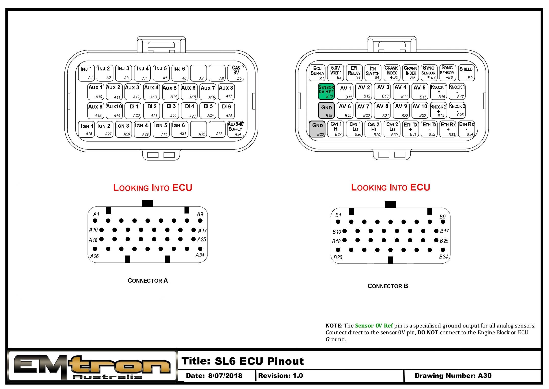
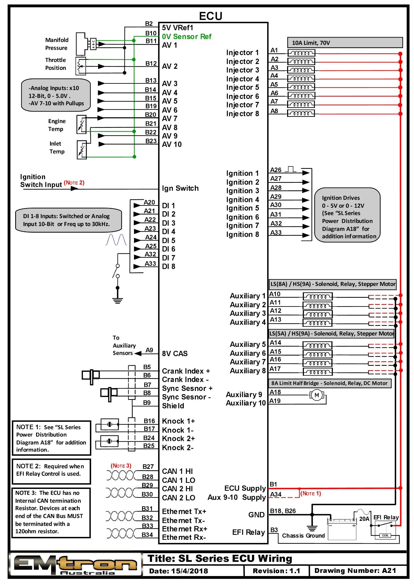
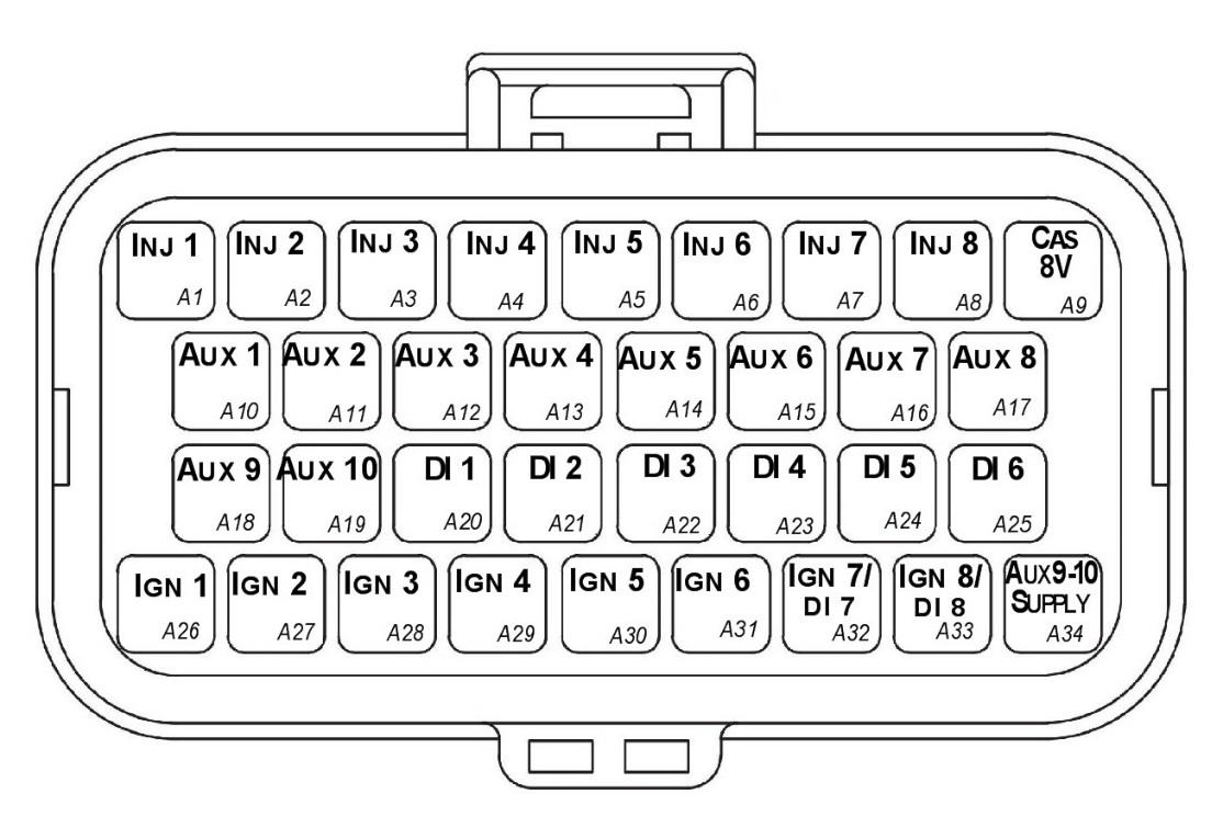
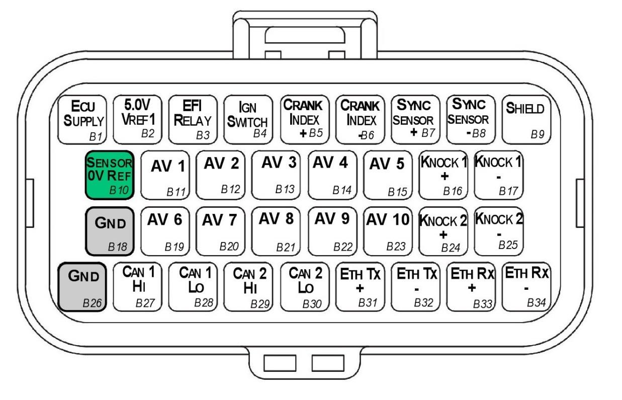
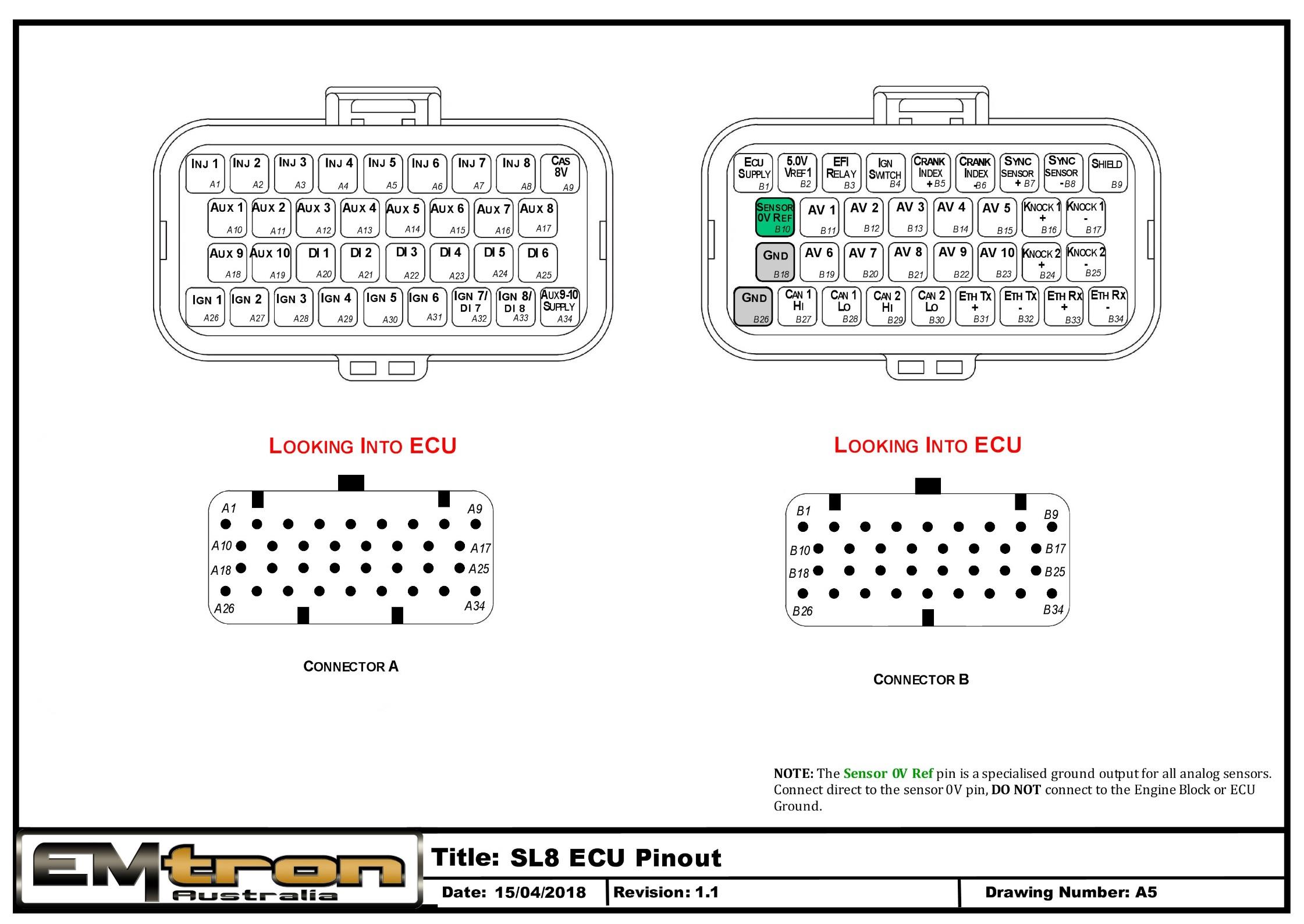
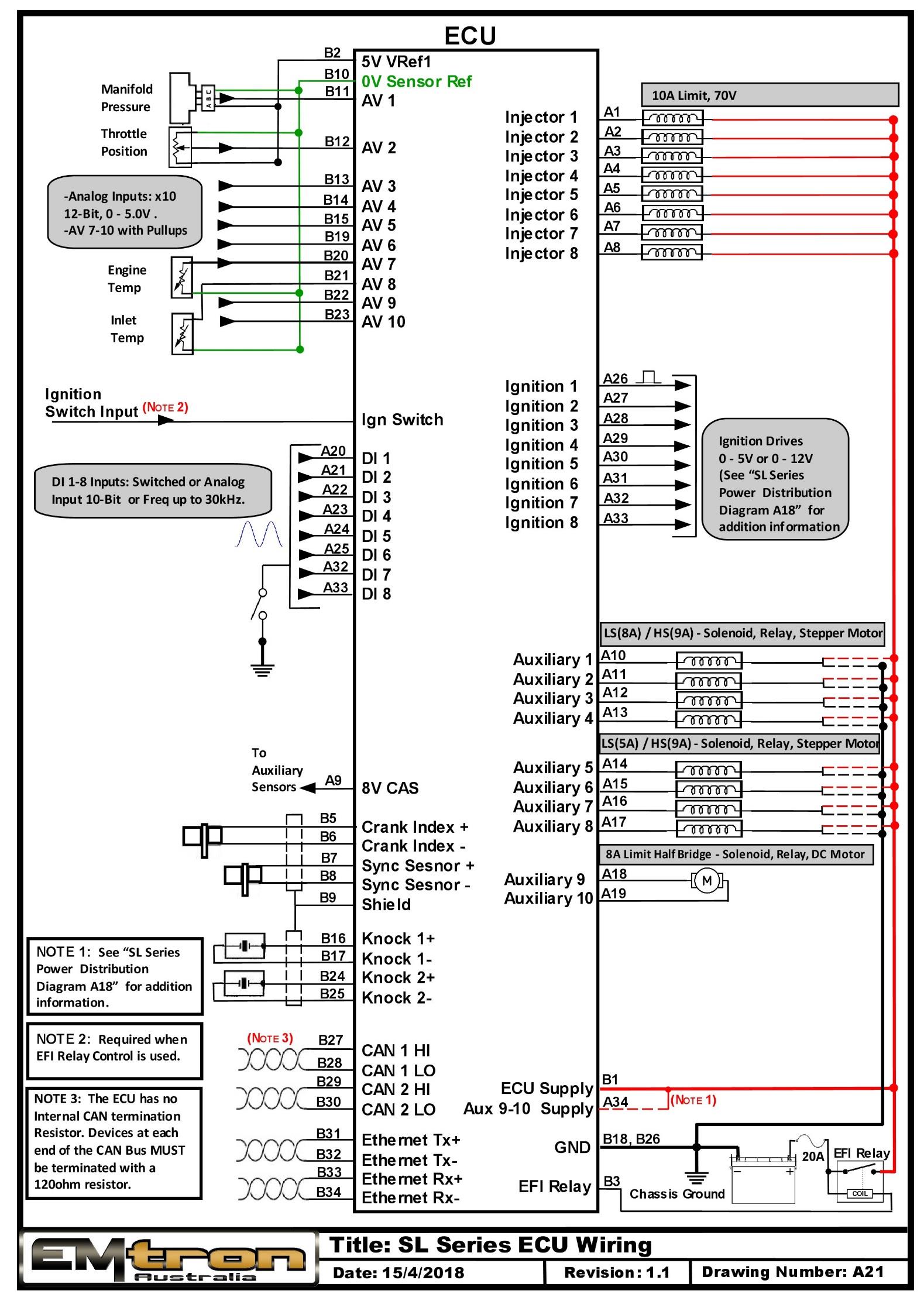
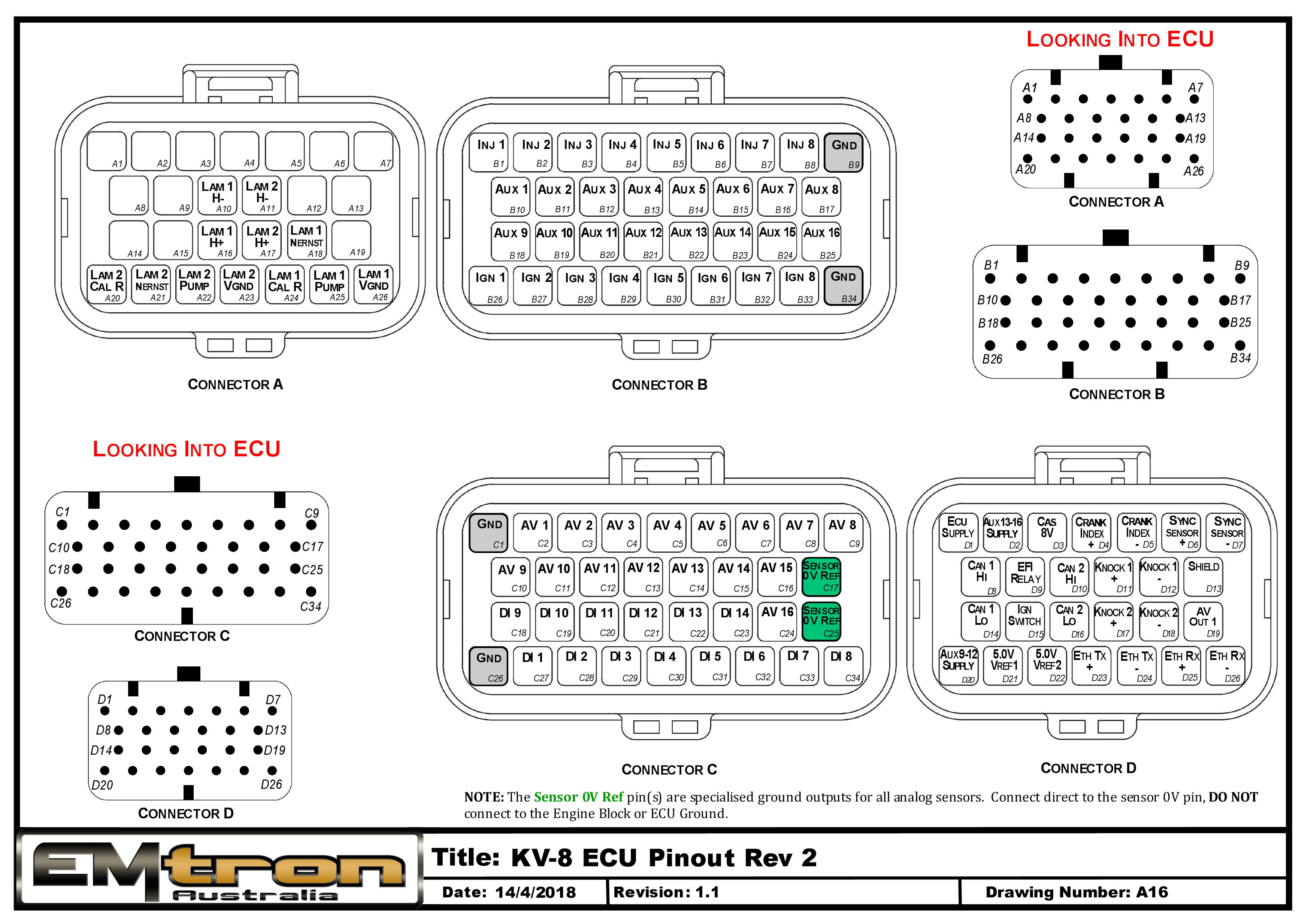
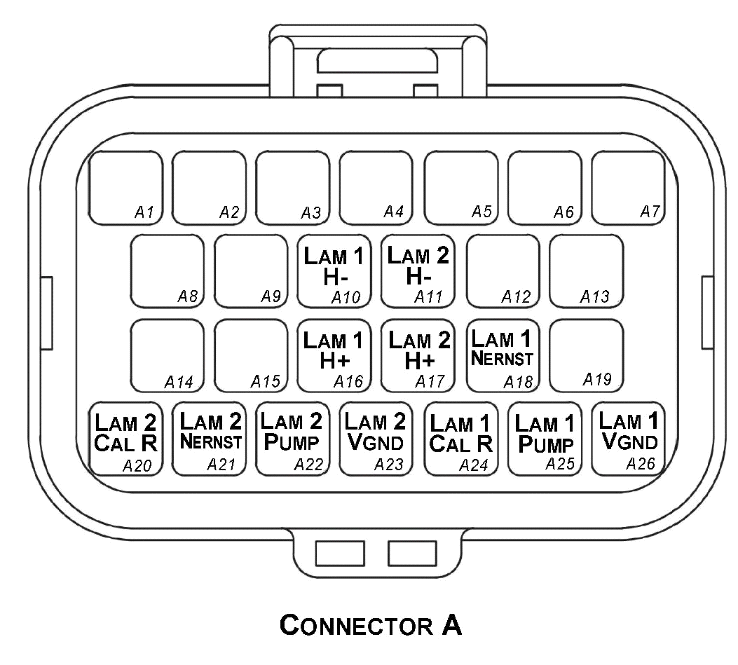
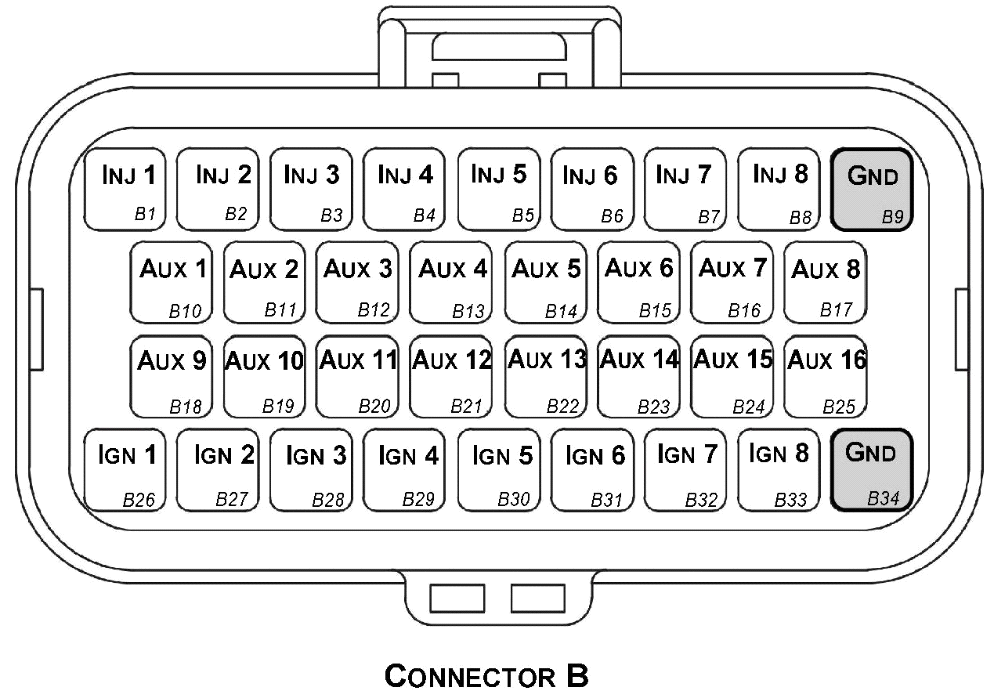
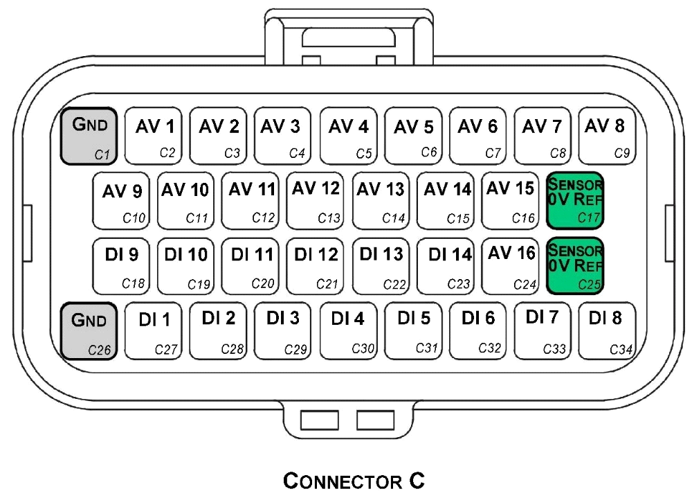
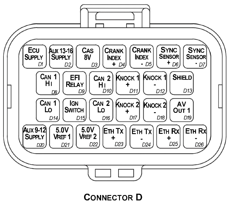
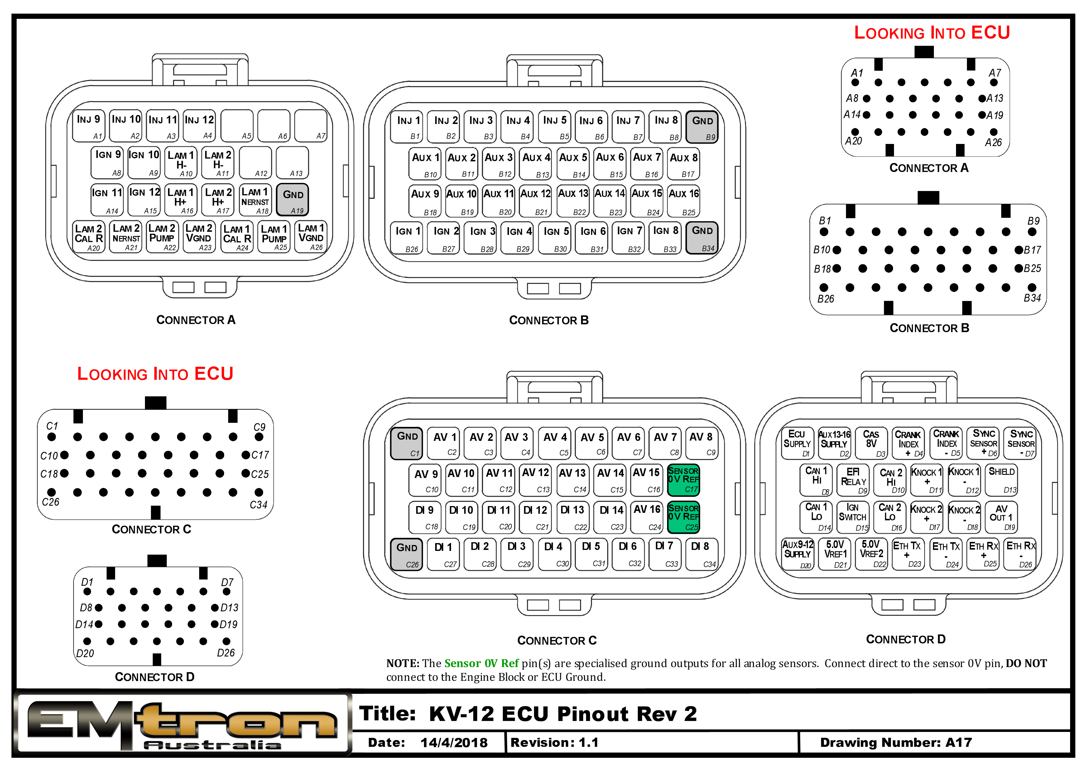
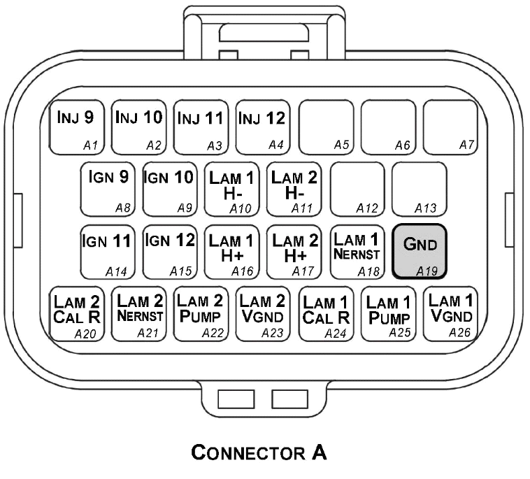
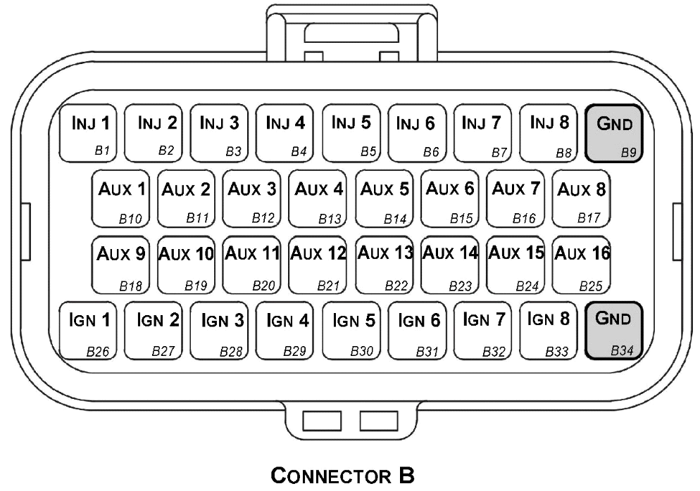
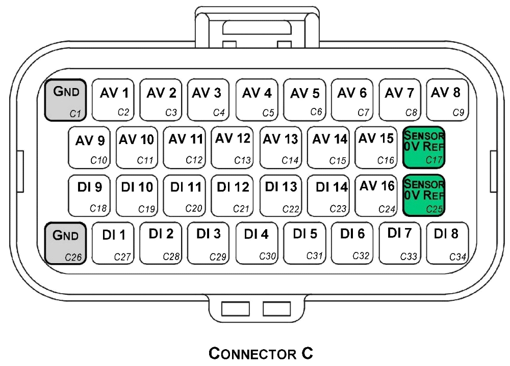
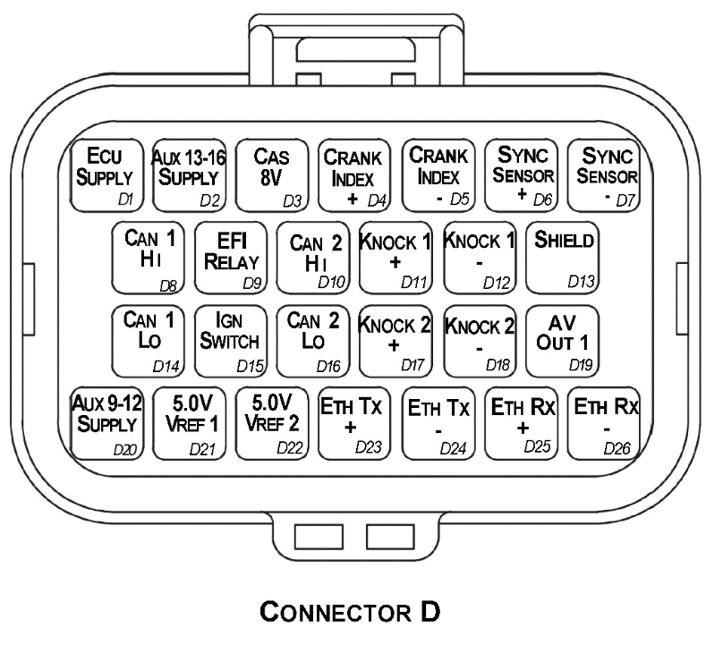
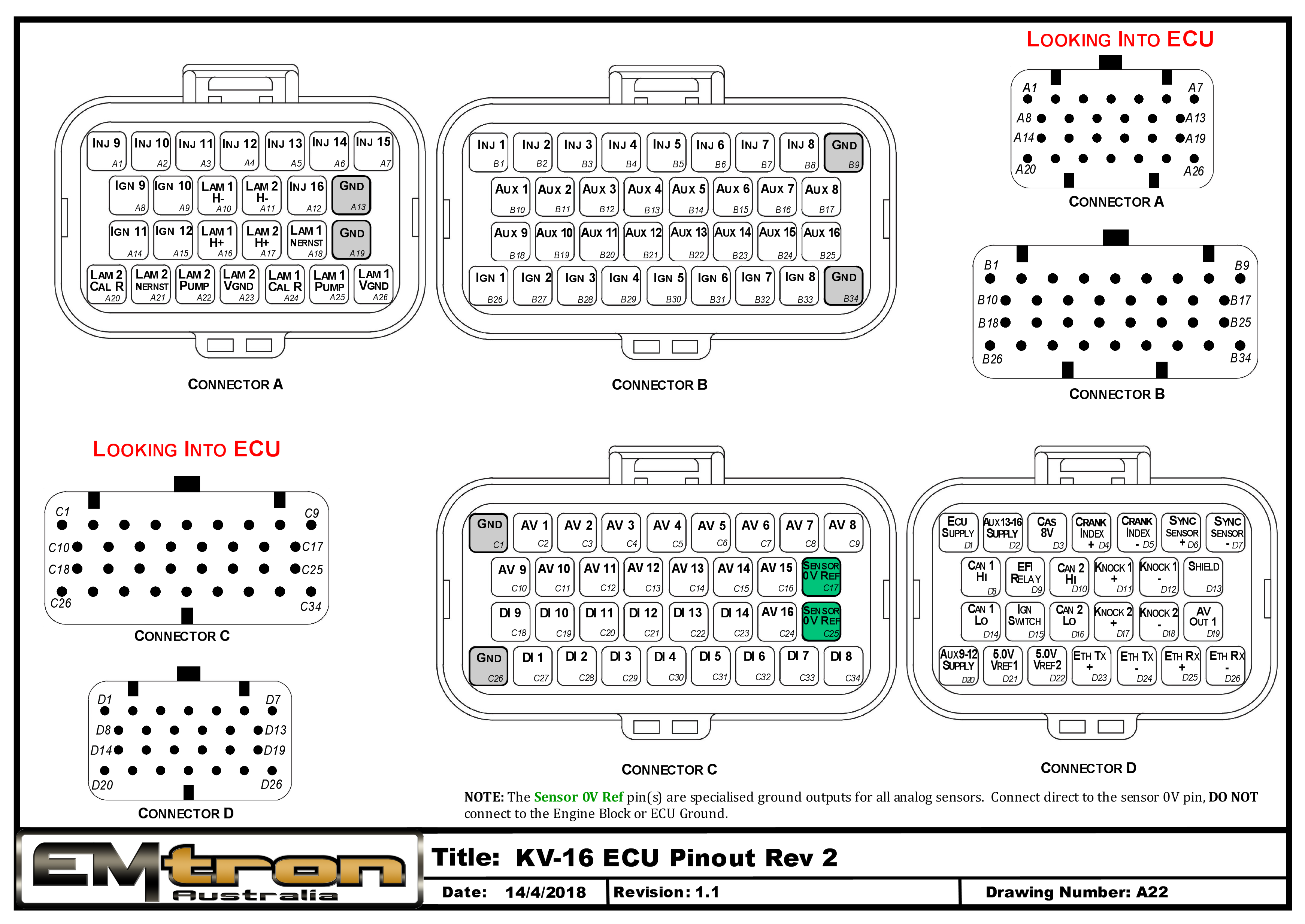
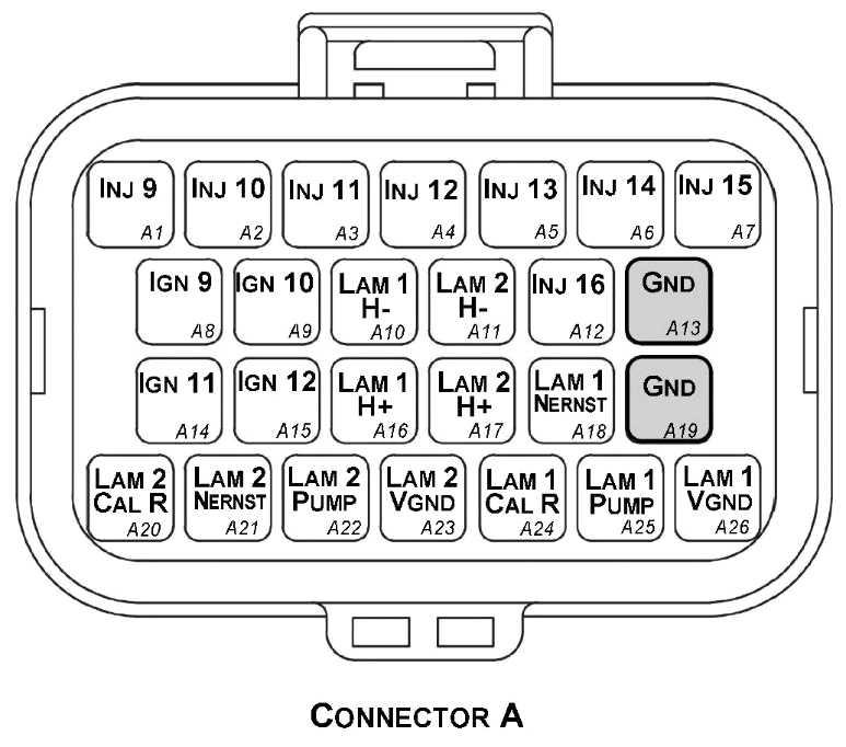
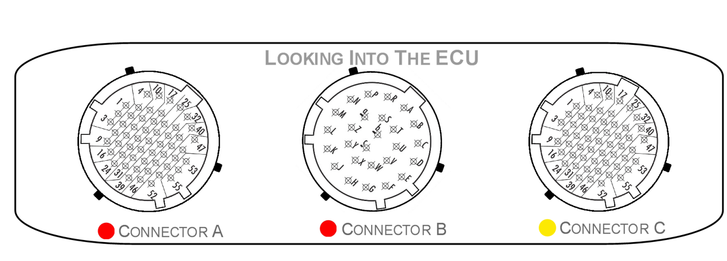
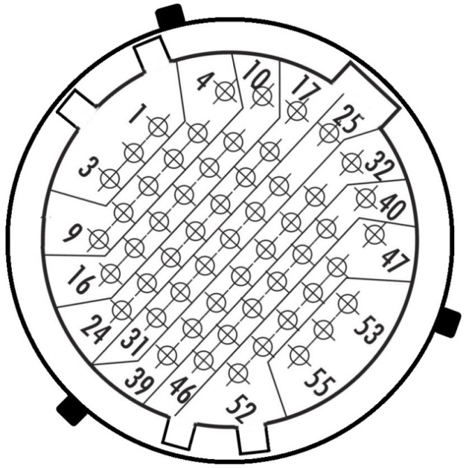
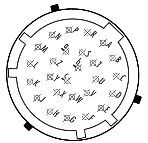
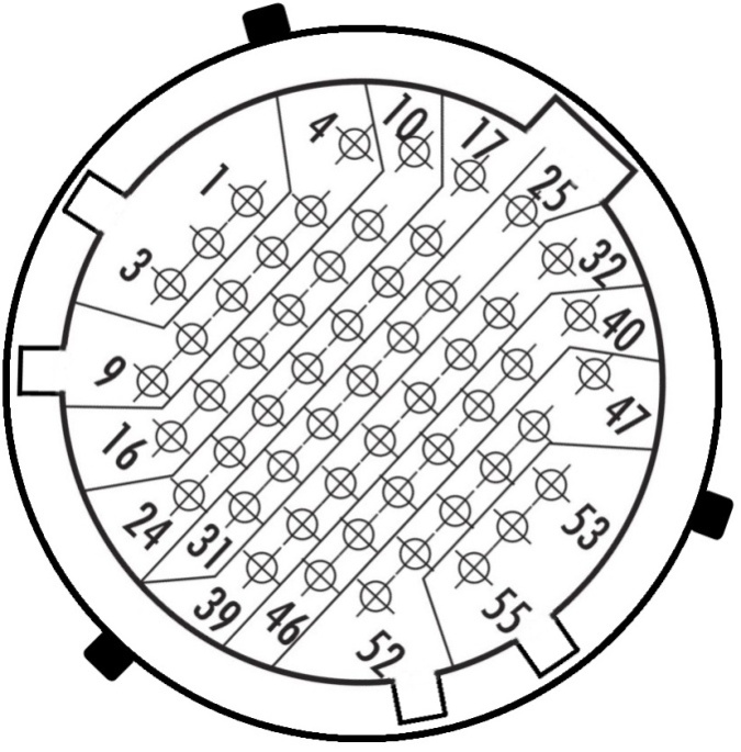
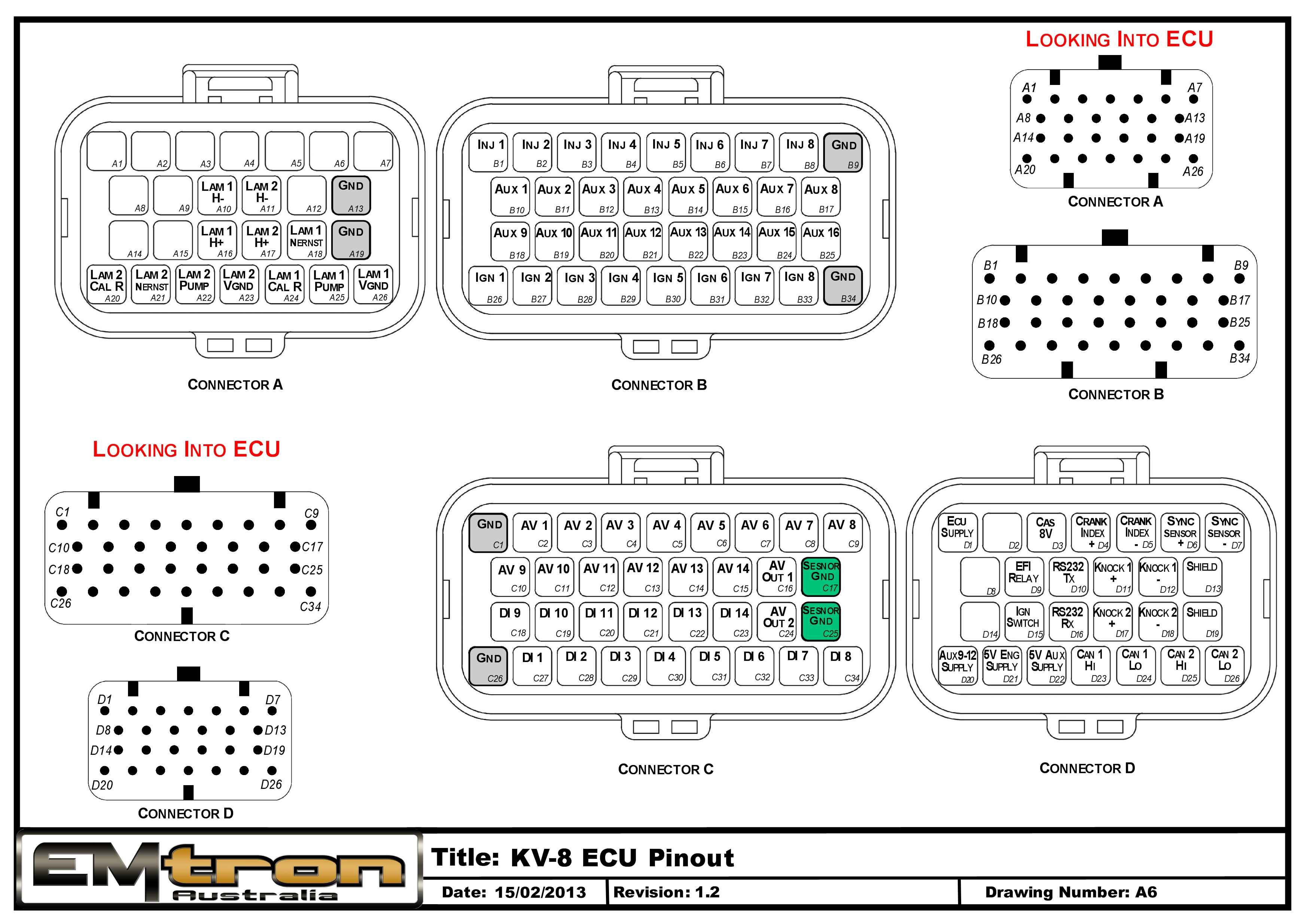
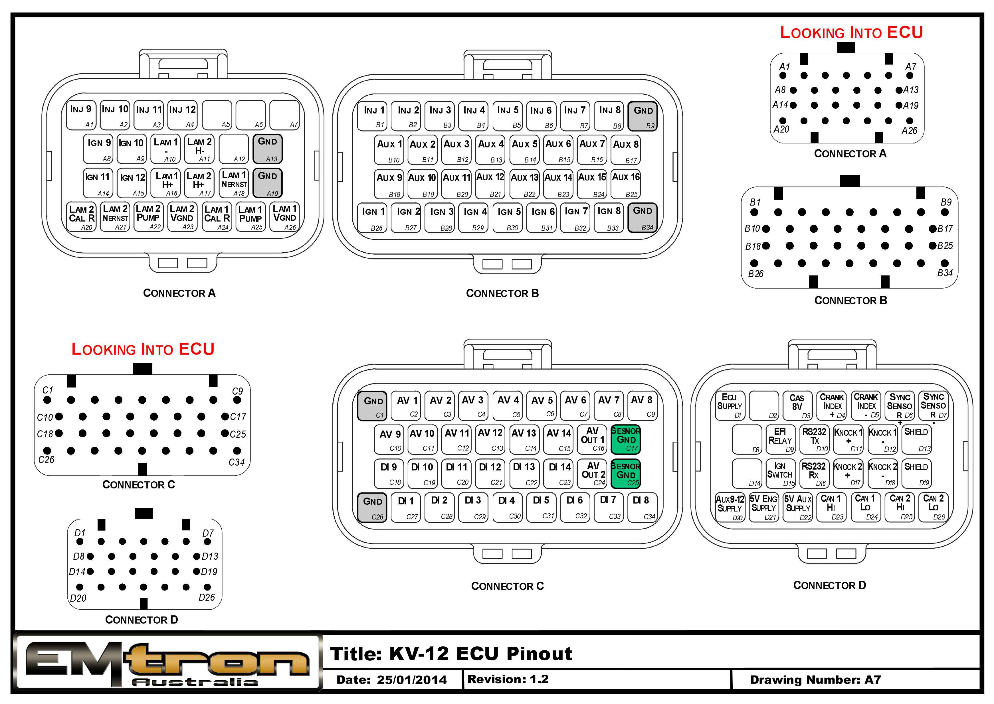
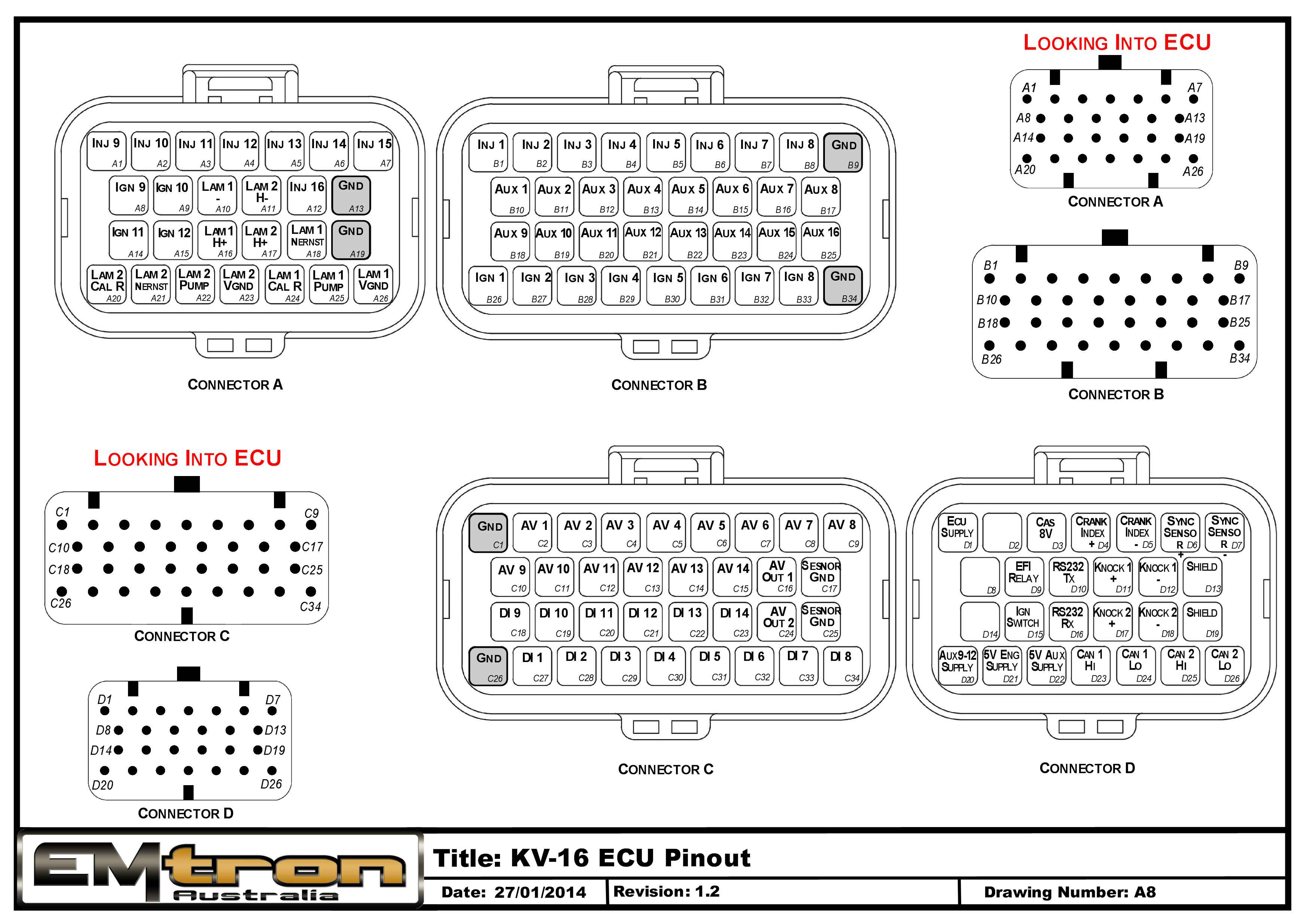
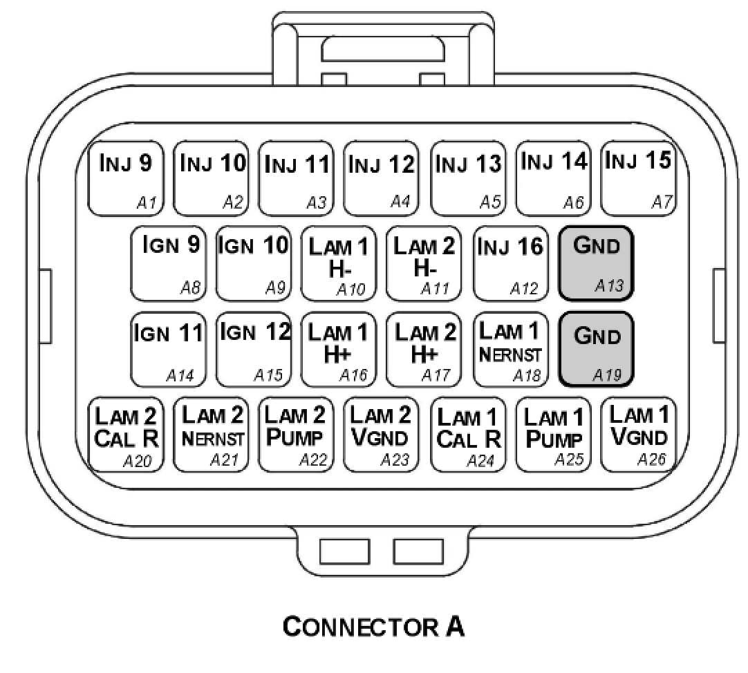
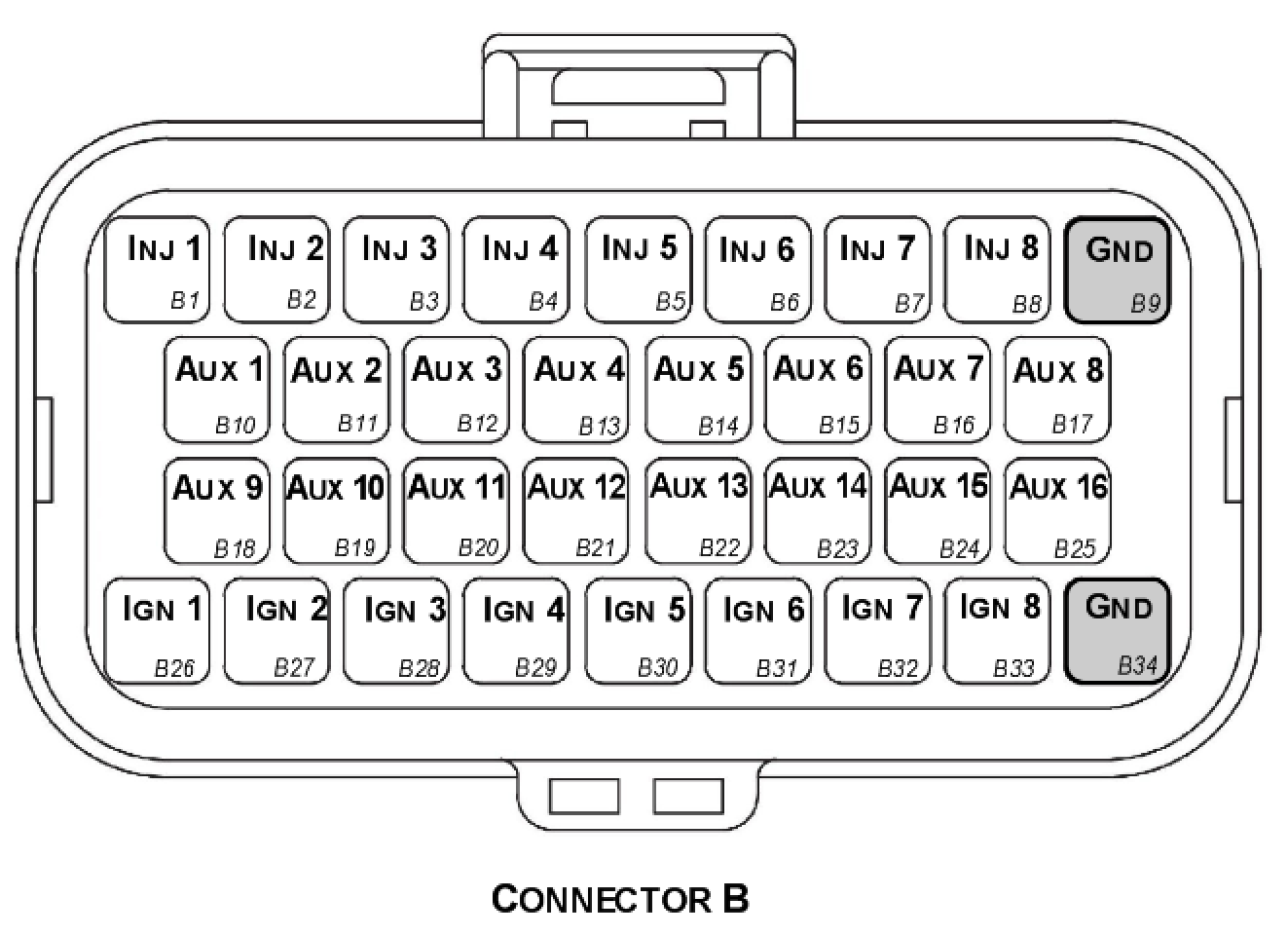
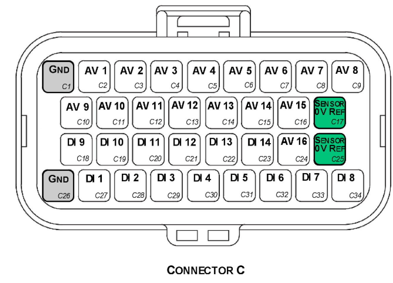
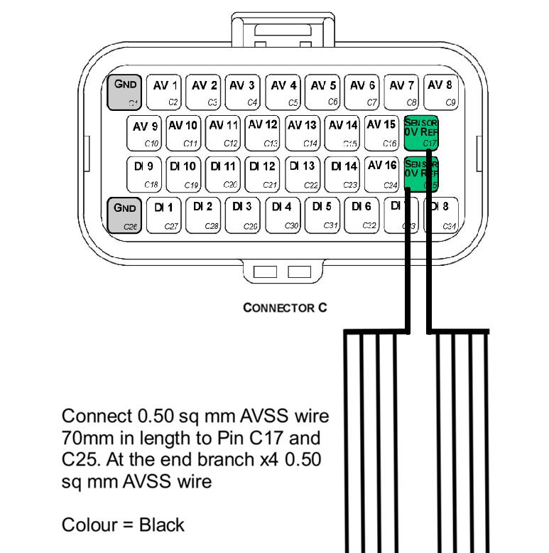
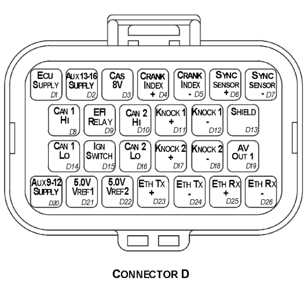
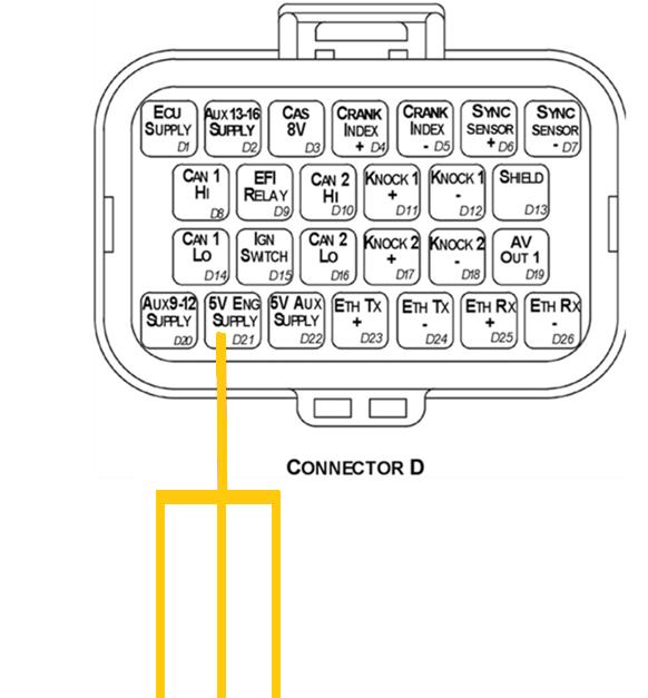
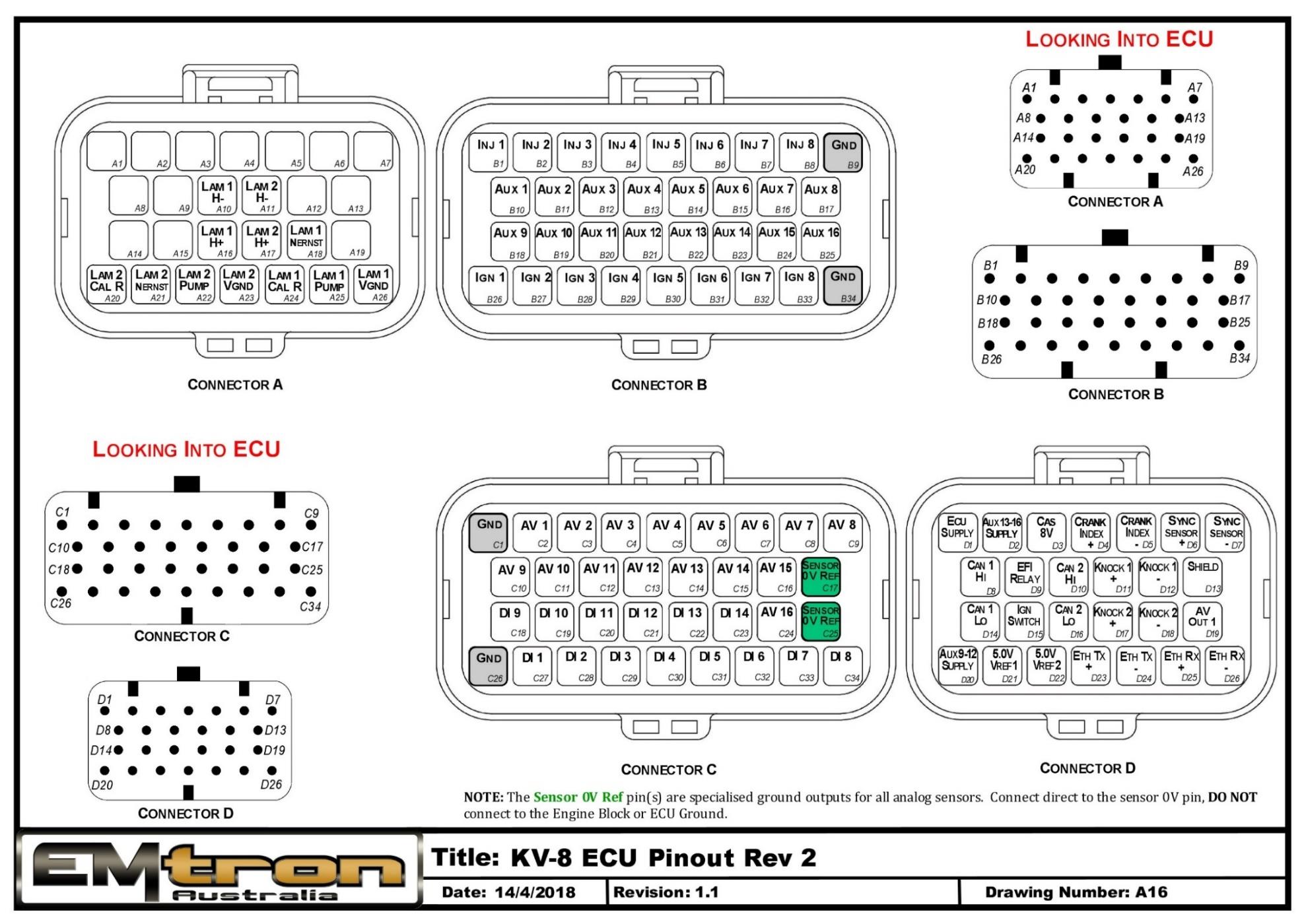
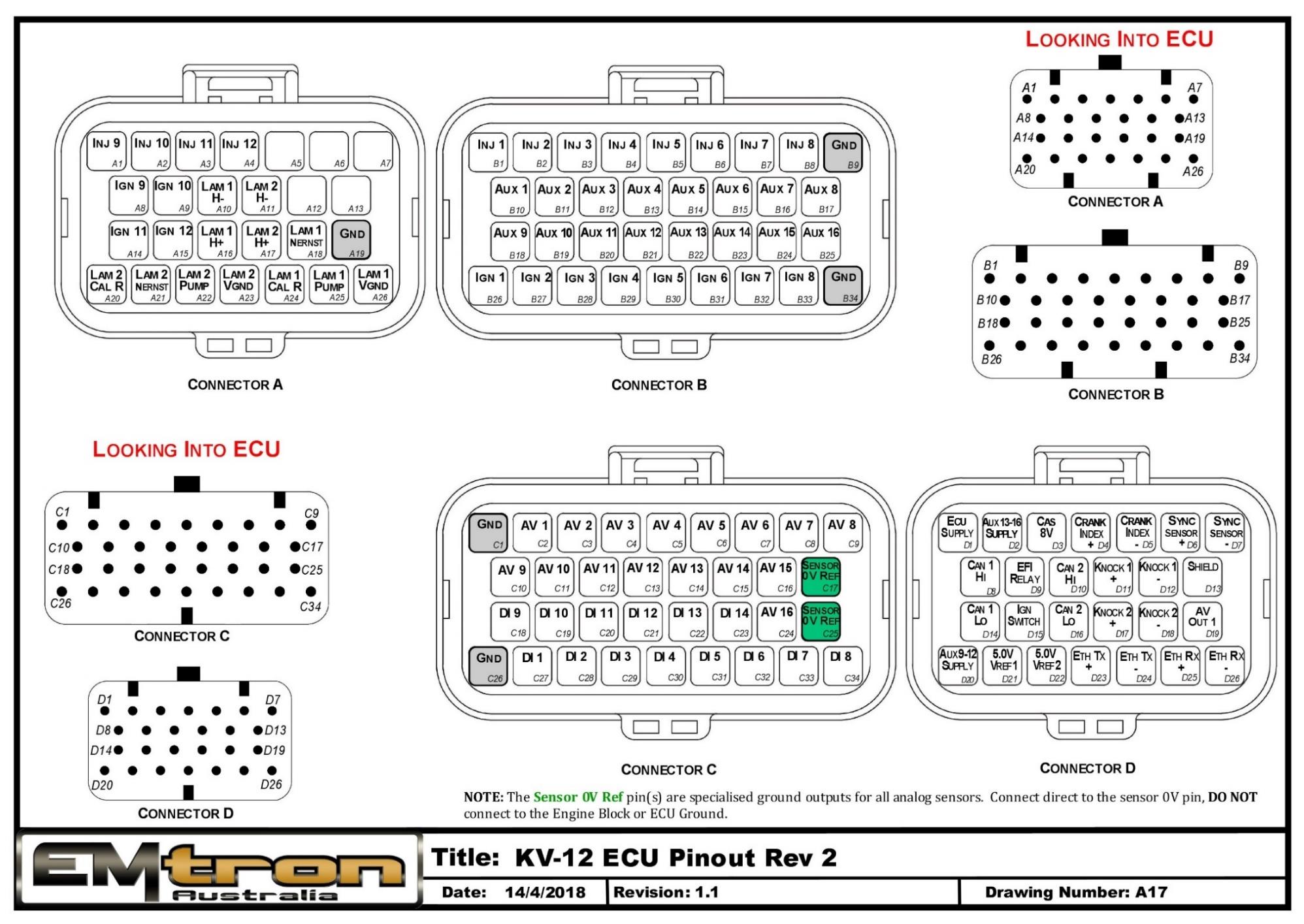
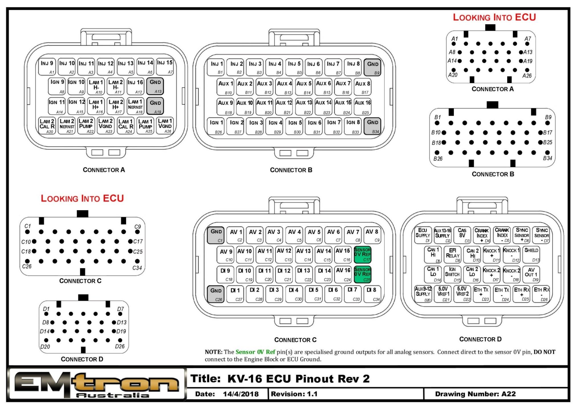
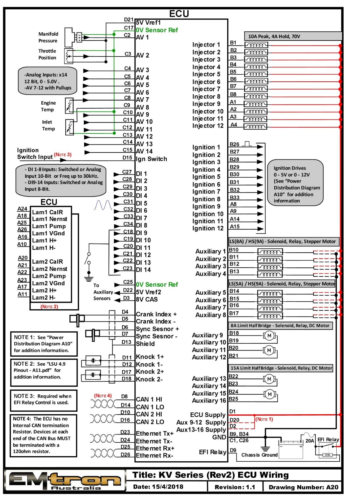
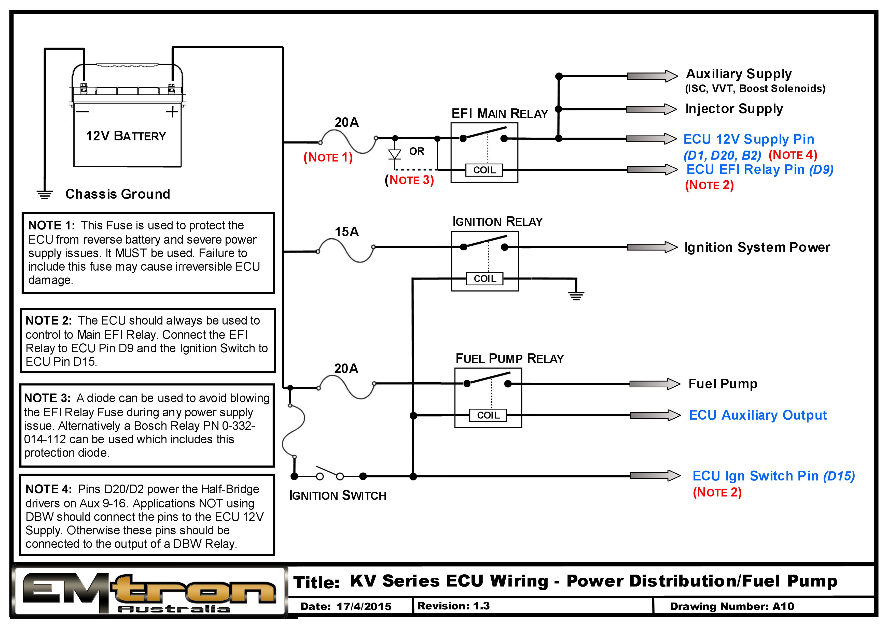
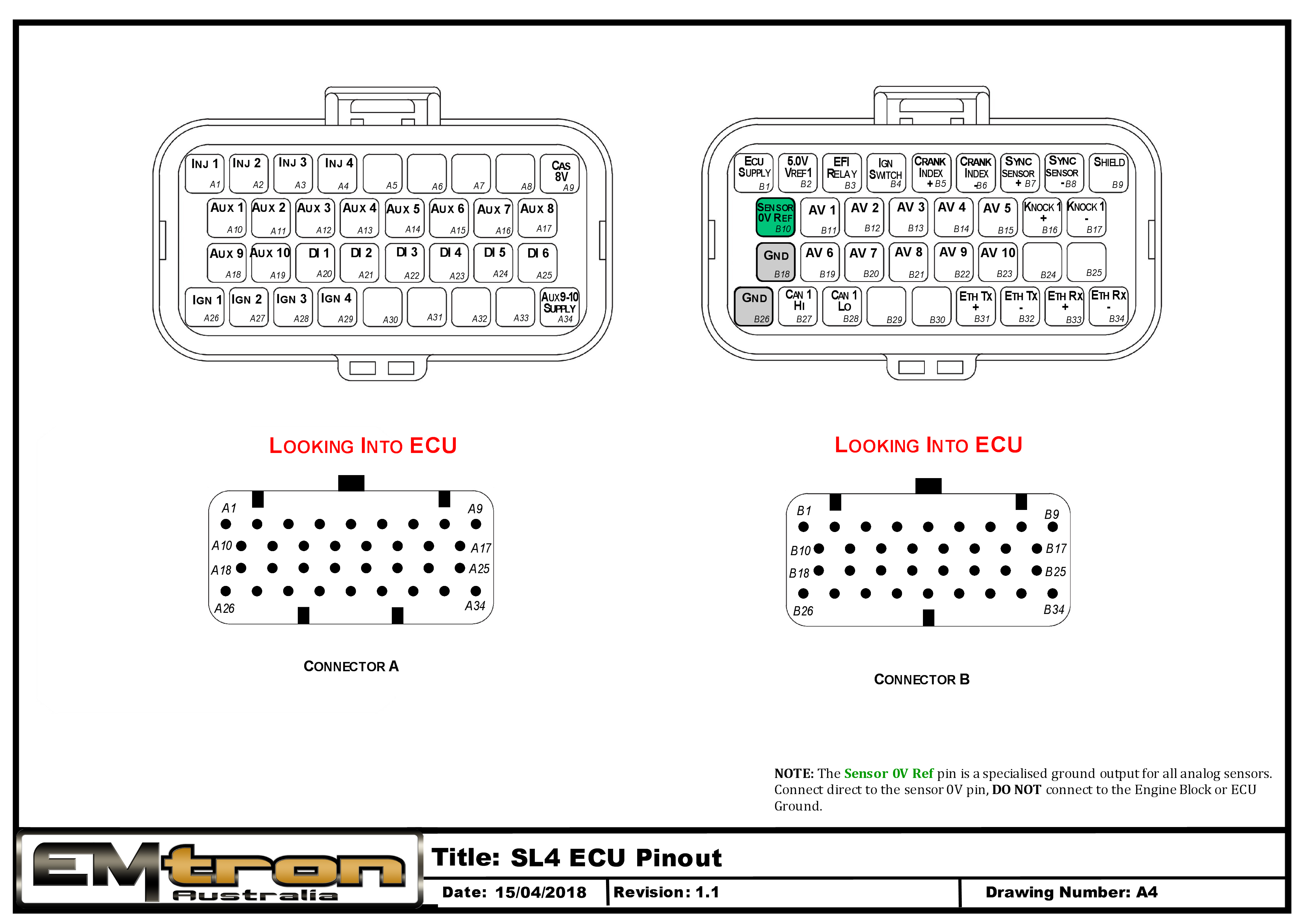
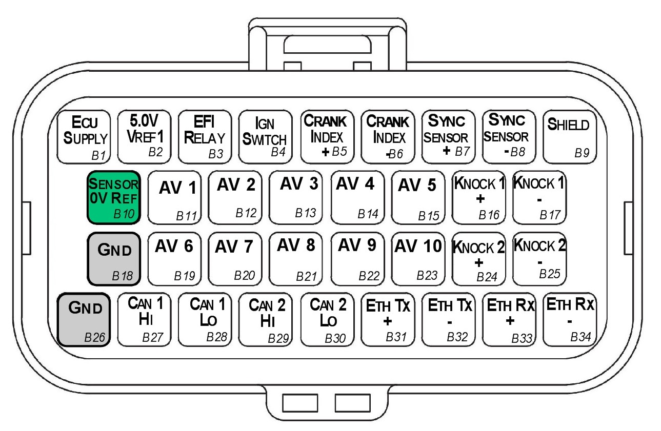
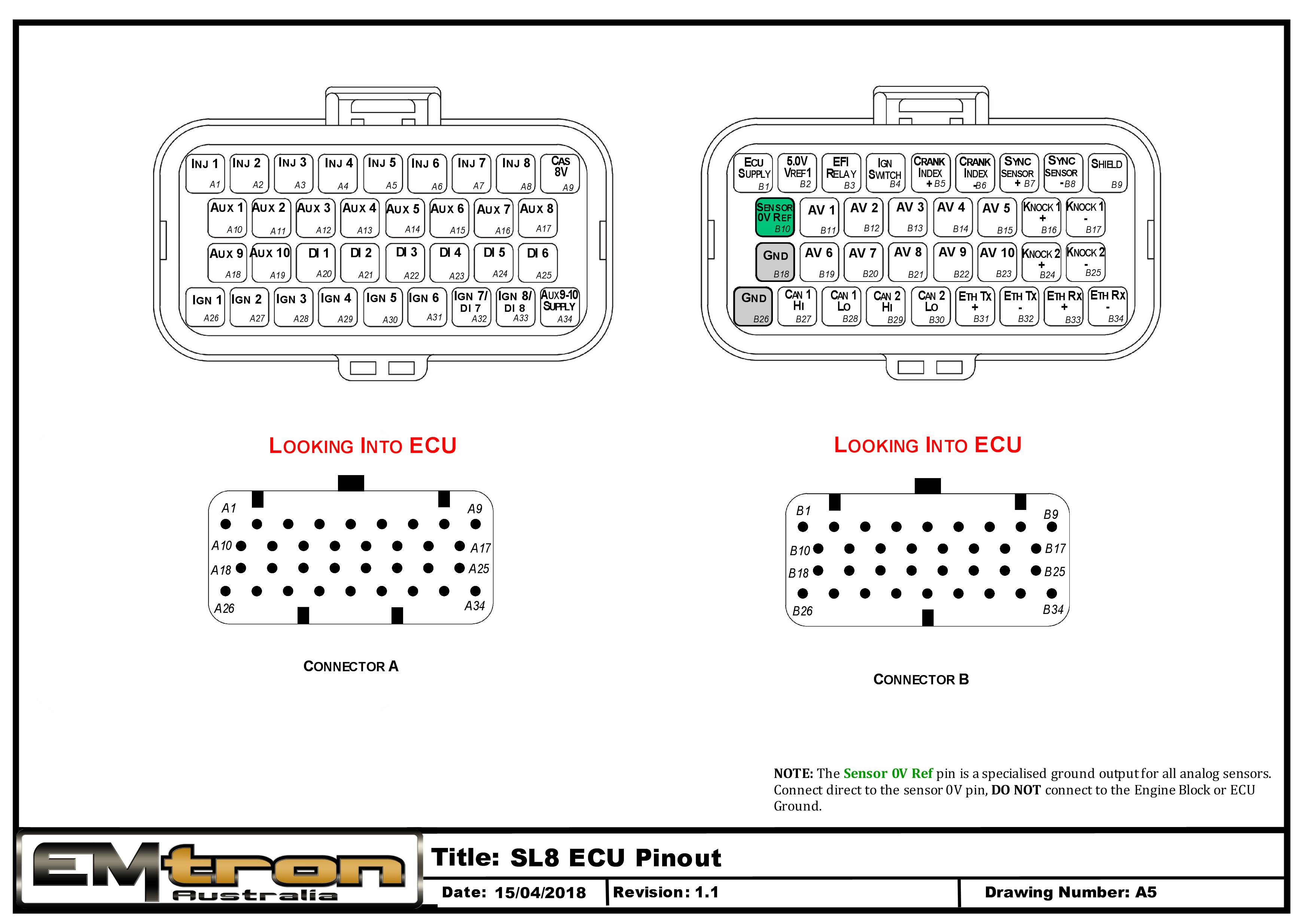
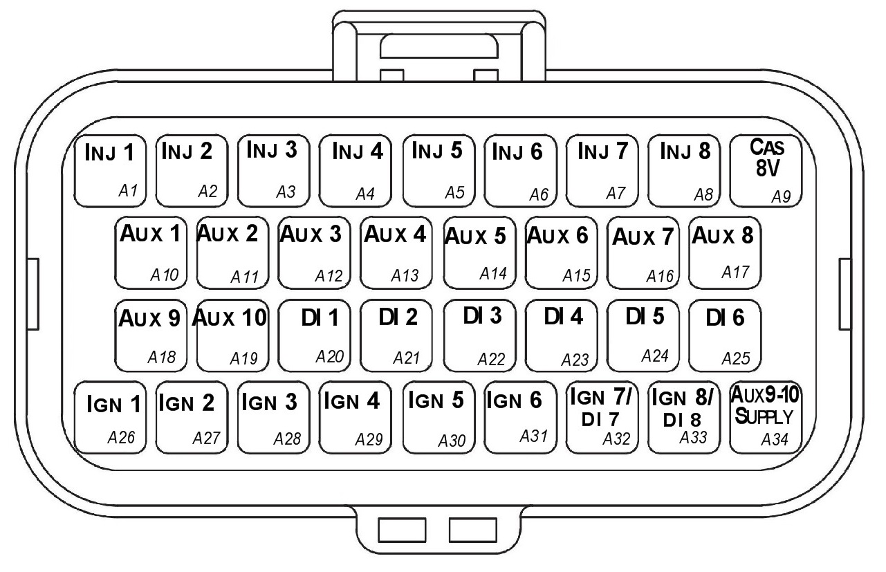
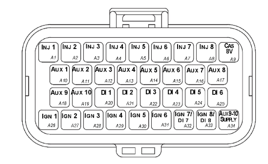
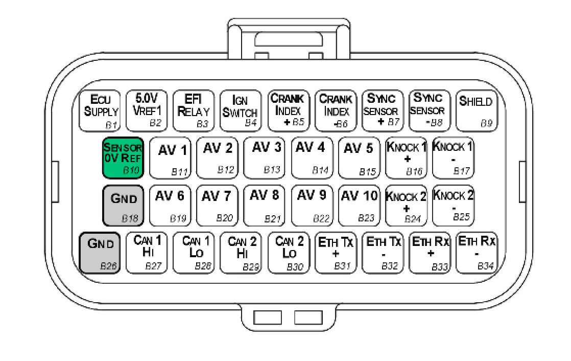
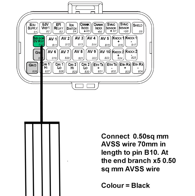
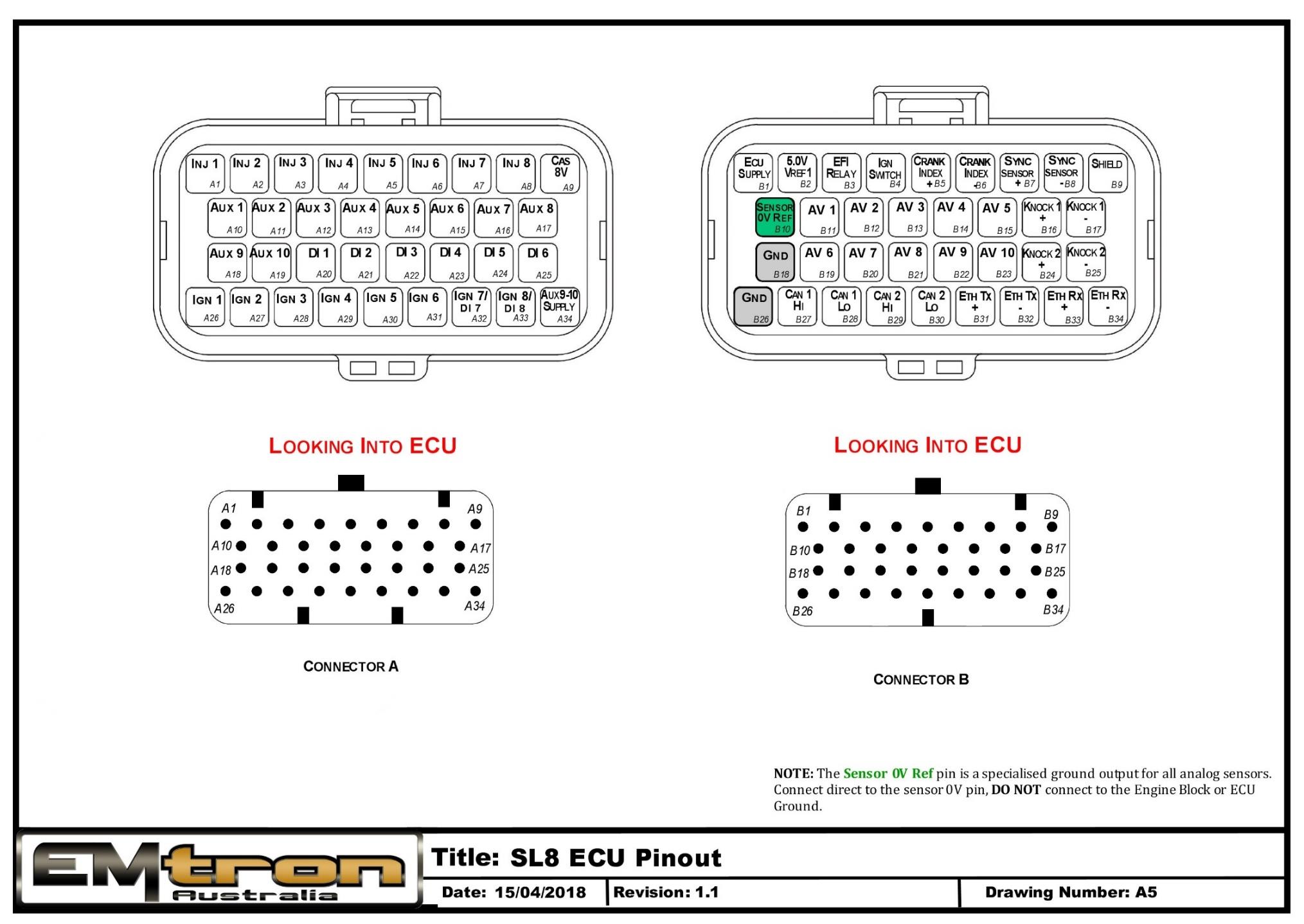
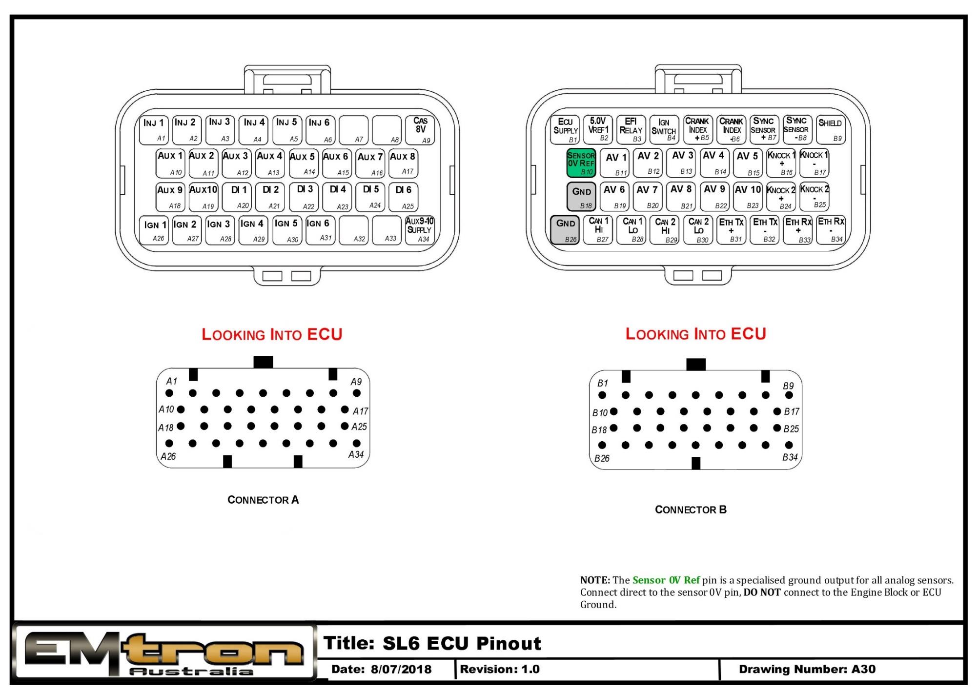
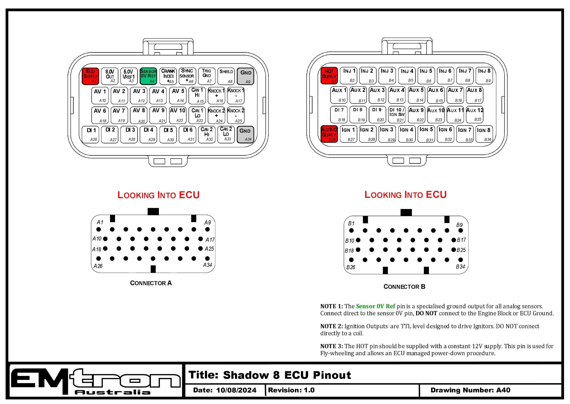
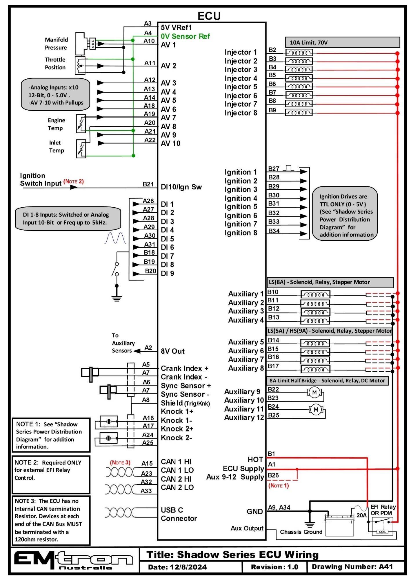
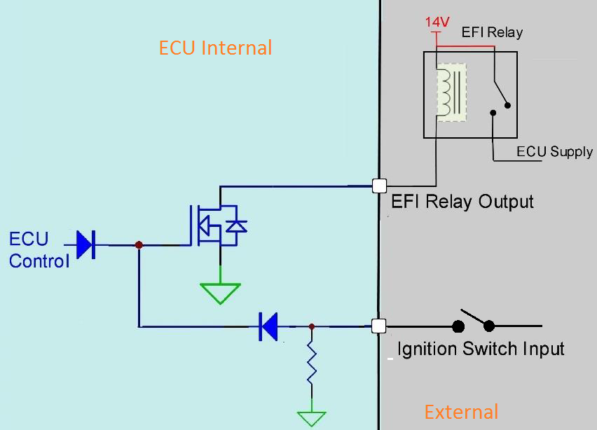
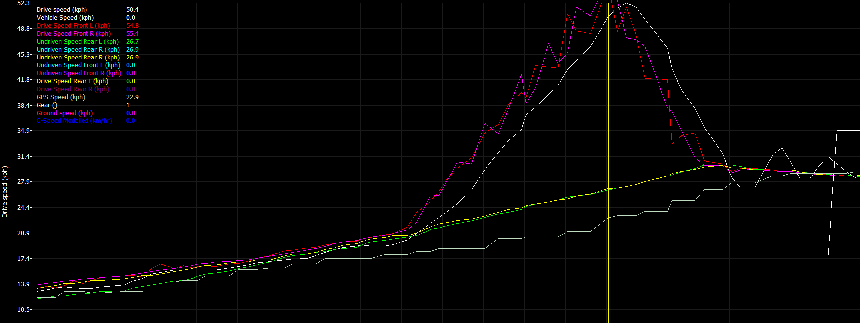
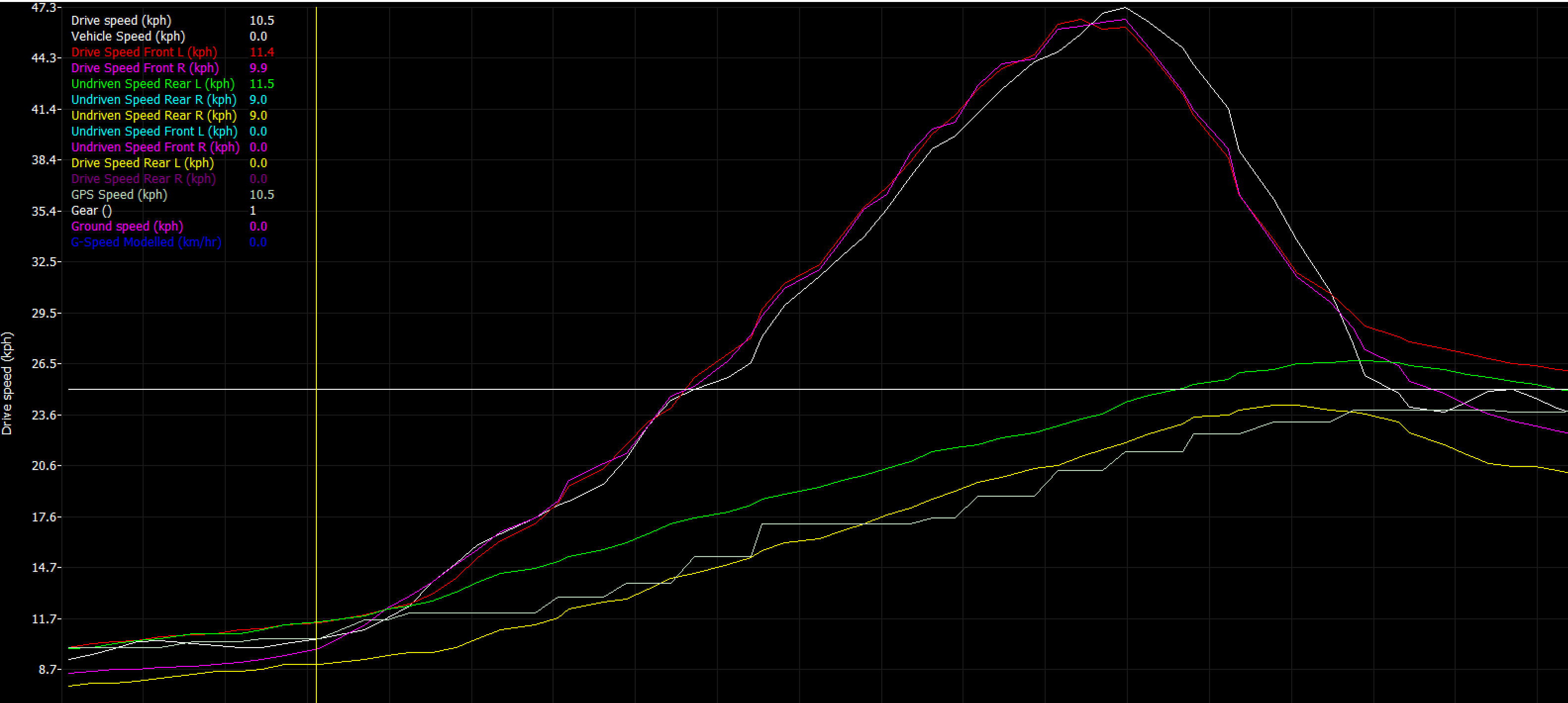
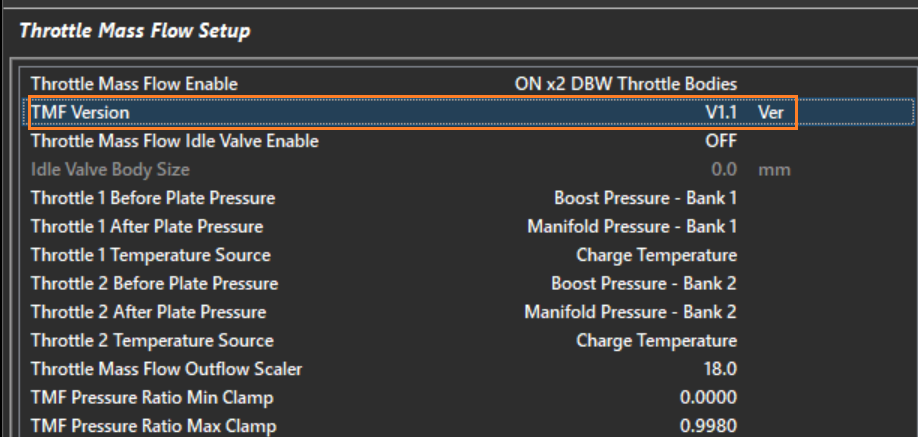
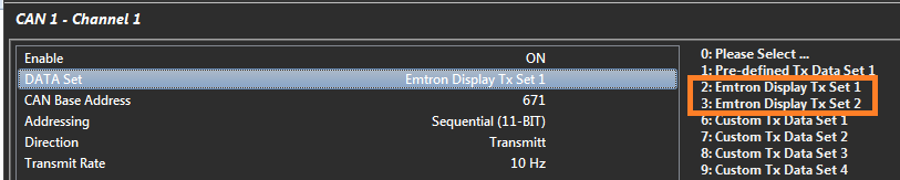
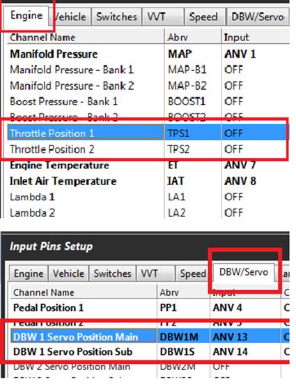
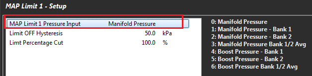
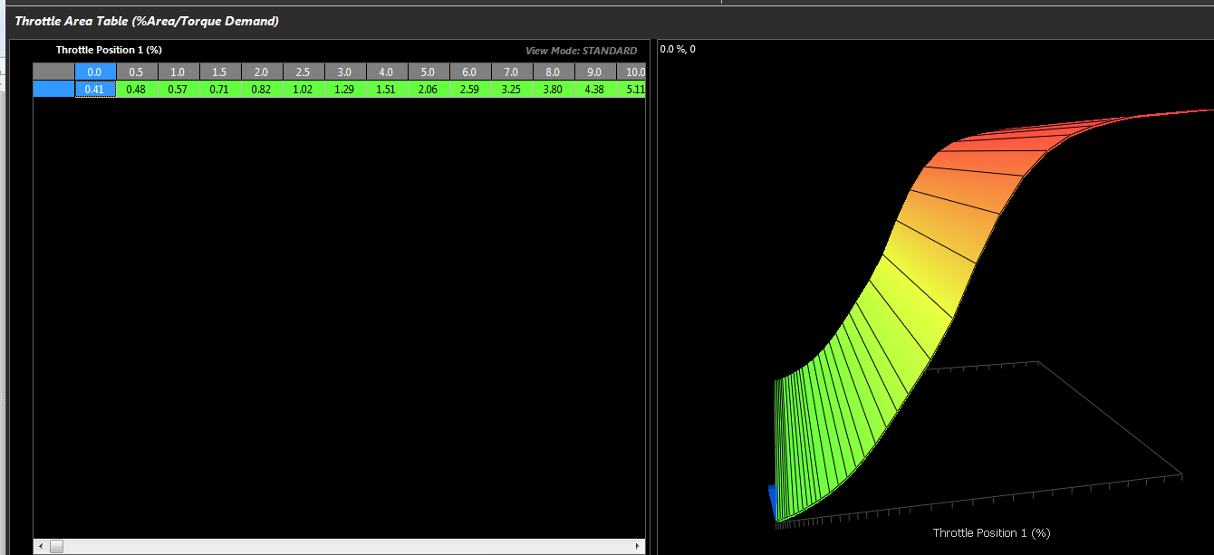
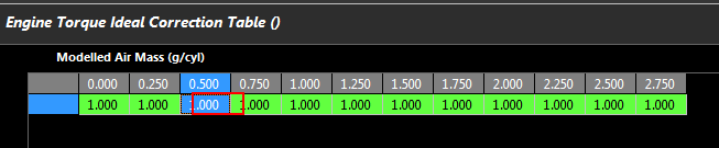
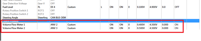
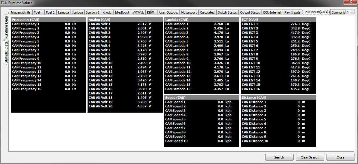
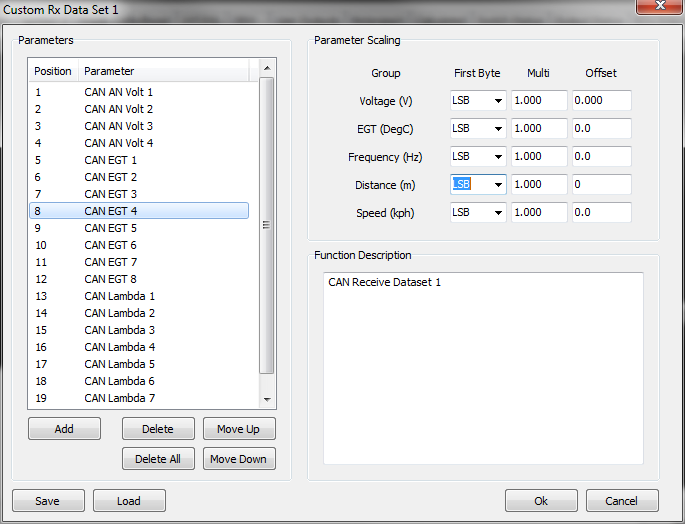
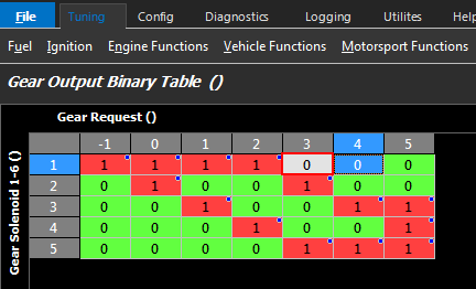
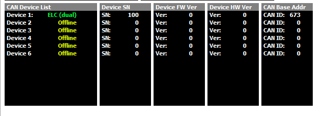
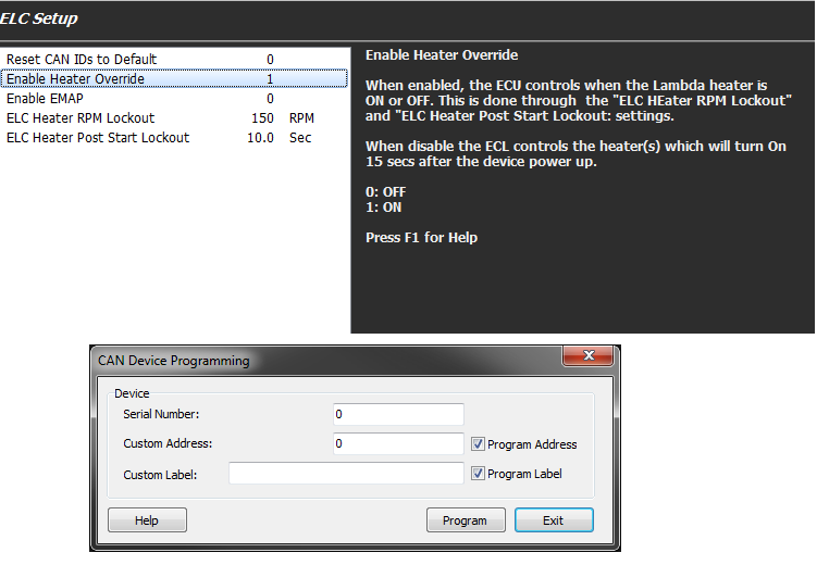
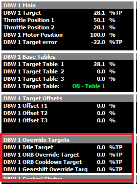
For detailed CAN bus information refer to the Communications documentation.
Start files or Base Maps
Some base cal files are included with Emtune and can be found in: C:\Emtron\Cal Files\.
For application specific examples please contact Support.
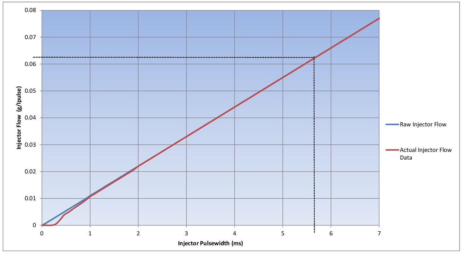
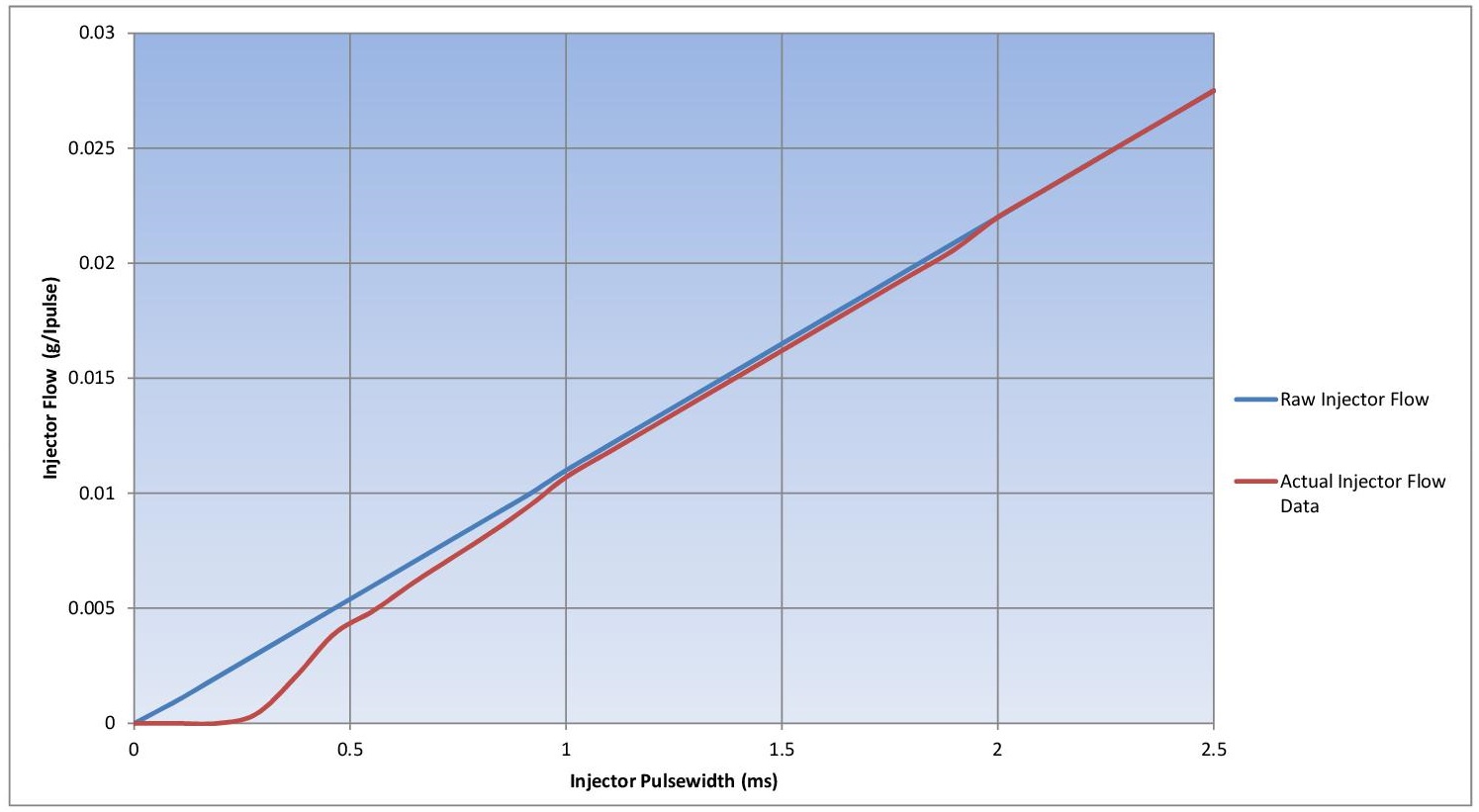
Injector Data
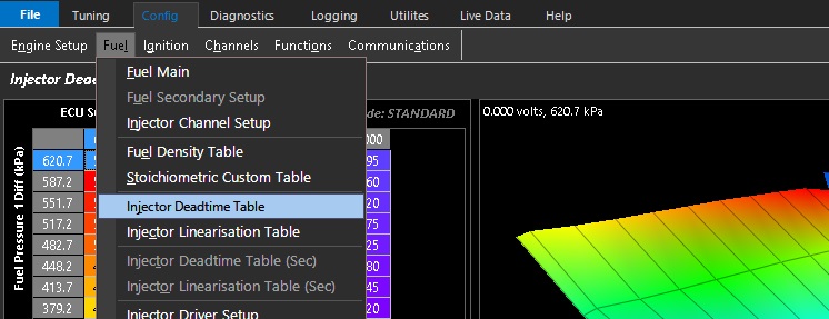
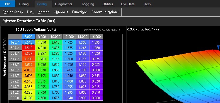
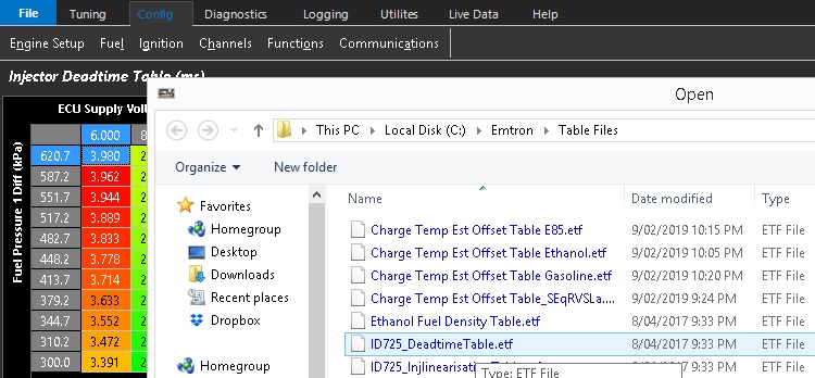
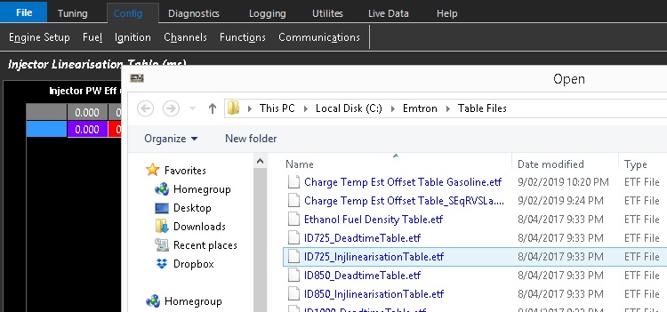
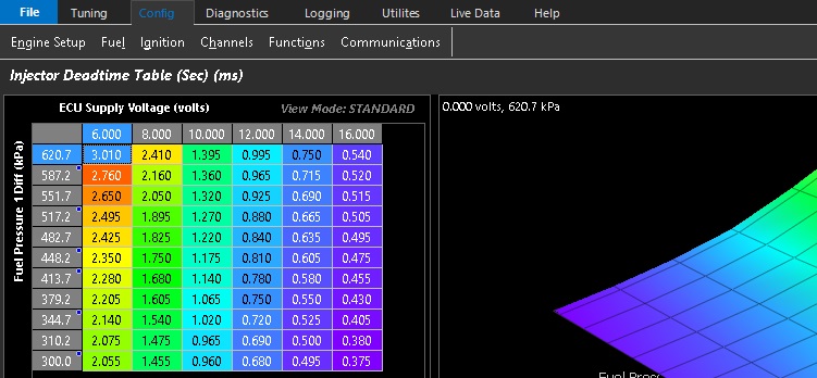
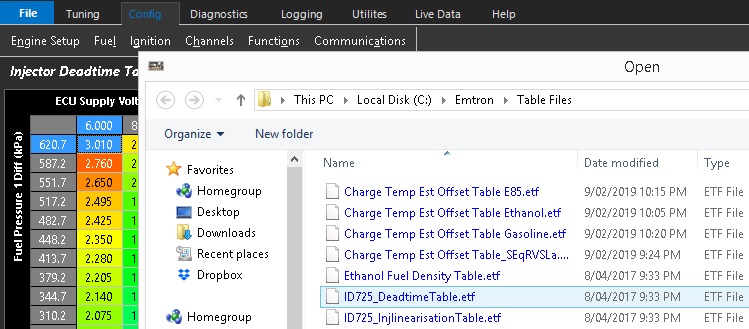
Many common injector deadtime and linearisation tables are included with Emtrun and can be found in: C:\Emtron\Table Files\Injector Data Tables.
Subsections of FAQ
Emtron ECU Features
There’s no shortage of engine management platforms on the market today. It’s not much of a leap to say that most of them can achieve similar results when operated by someone familiar with them. So, what makes Emtron different? Extreme flexibility coupled with advanced engine modelling not typically found in aftermarket engine management. This includes the Emtron mathematical torque model, which is a true paradigm shift in the way we approach torque management, motorsport functions, and engine management in general. This is made possible by the Emtron’s advanced air mass modelling.
Air Mass Modelling
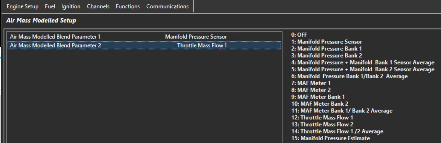
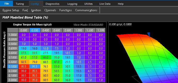
Emtron ECU’s feature a sophisticated air mass model not usually found outside the OE market. The air mass entering the engine is accurately calculated from a variety of sources to allow maximum flexibility of engine tuning. Numerous air mass calculations can be blended in almost any way, giving the tuner maximum flexibility to account for any situation or edge case. Tuning in terms of air mass instead of raw manifold pressure gives a far greater insight into the dynamic operational conditions of an engine. Tuning in terms of Air Mass Flow can greatly simplify many engine systems, reducing complexity and reducing guess work.
Bank or Engine MAP Air Mass
Bank or Engine MAF Air Mass
Bank or Engine Throttle Air Mass
Driver Demand Air Mass
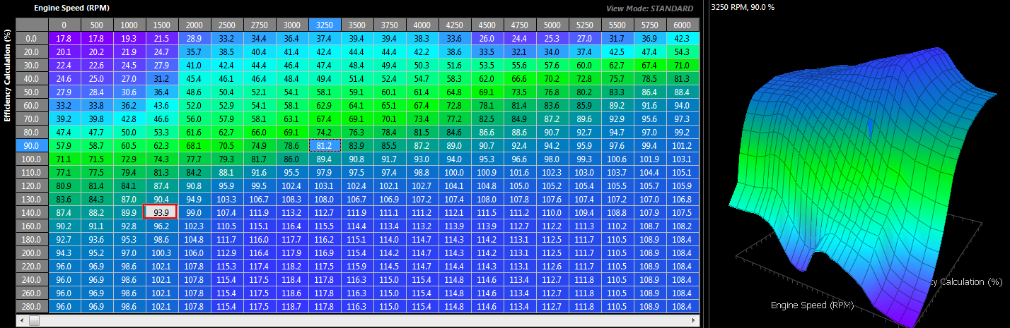
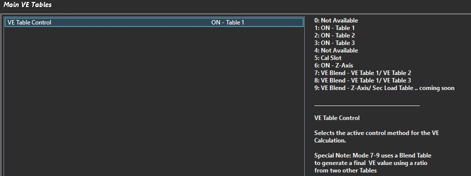
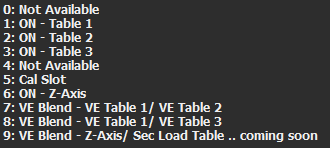
2x Volumetric Efficiency tables, freely configurable, switchable and Z-axis blendable
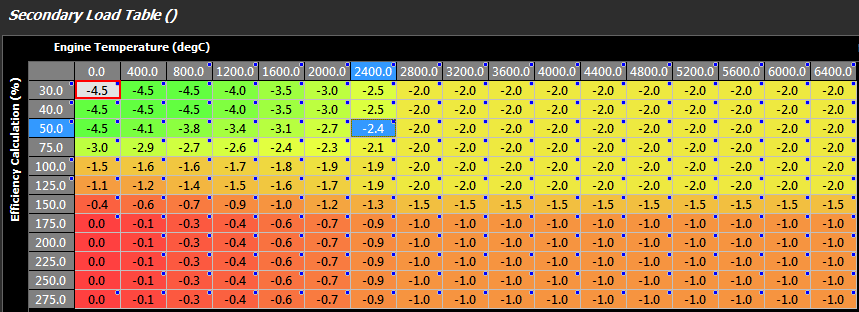
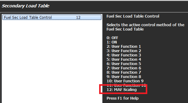
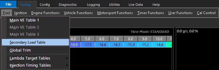
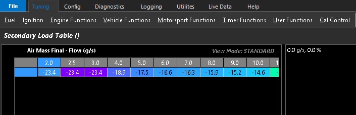
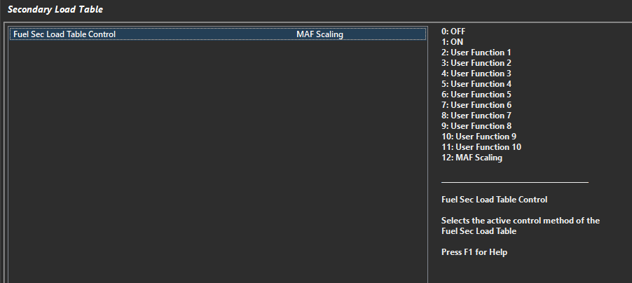
Secondary Load Table
Charge Temperature Estimation and offset tables
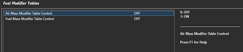
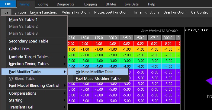
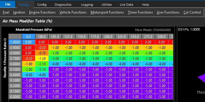
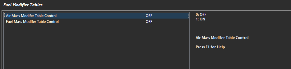
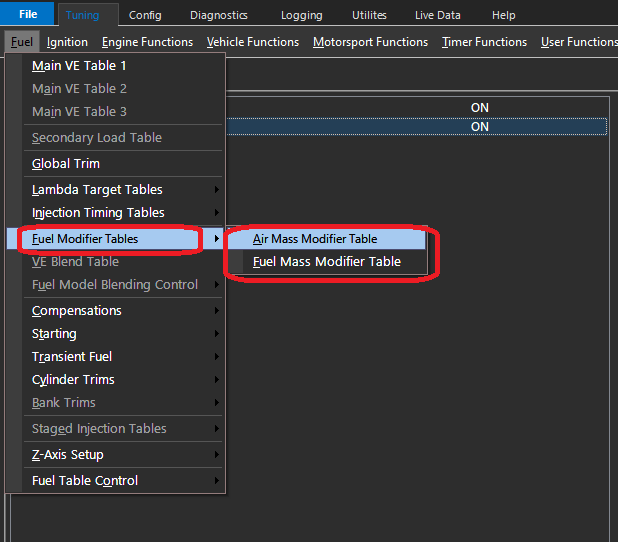
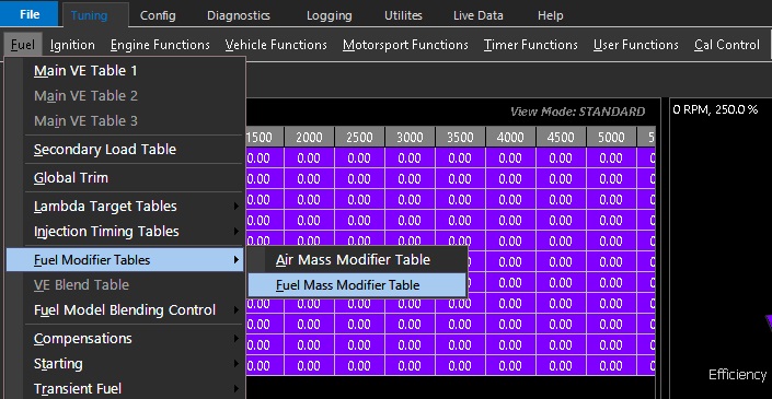
Air Mass Modifier table
Throttle Mass Flow
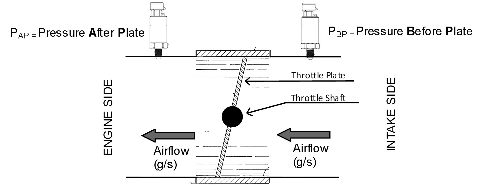
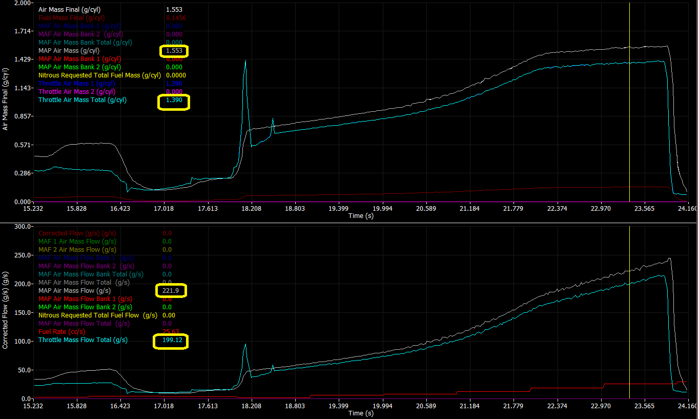
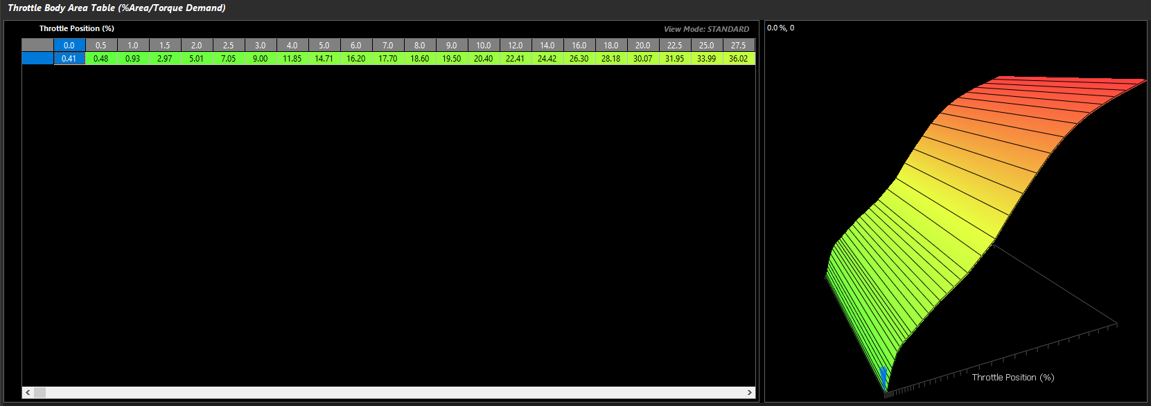
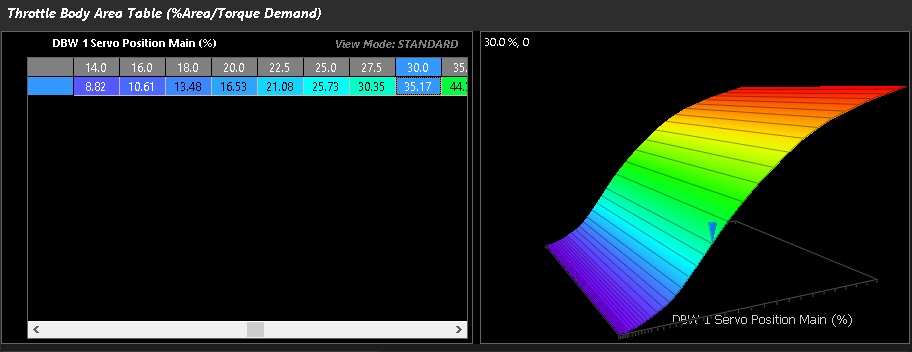
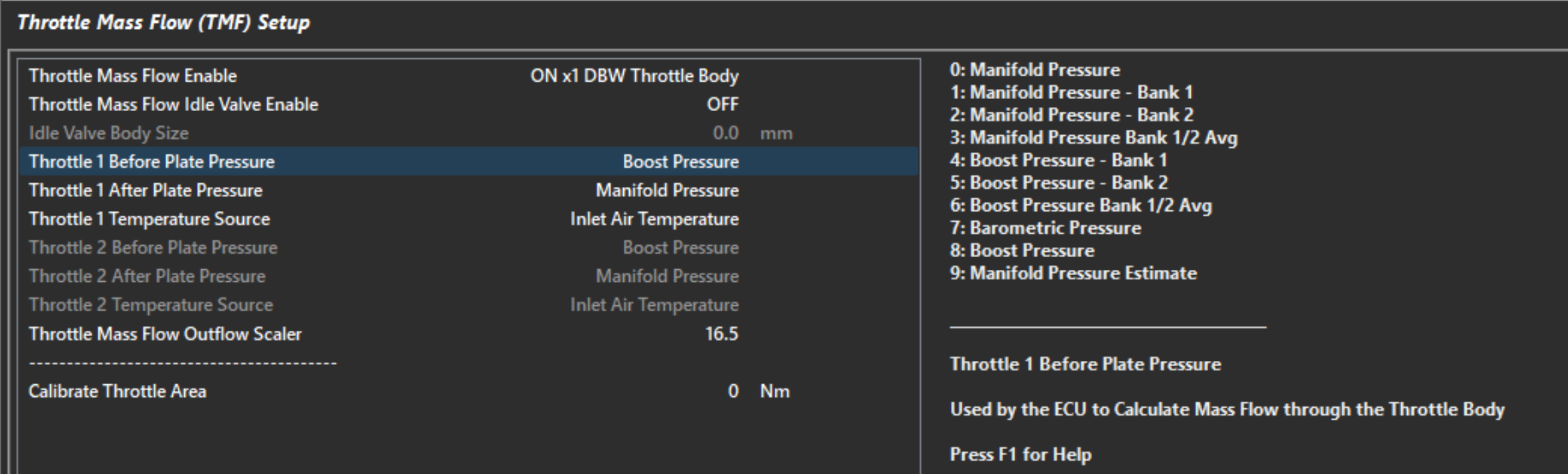
By measuring the pressure before and after a throttle body, Emtron’s TMF model essentially converts a throttle body into a mass air flow meter, providing a very dynamic and fast air mass calculation that’s perfect for accurately adhering to torque targets without the need for estimate tables or open loop guess work. Throttle Mass Flow modelling also opens up a huge variety of approaches to engine tuning and the ability to easily account for dynamics such as changes in cam timing without compensation tables.
Expansion Ratio
Emtron’s air mass model can account for changes in engine efficiency based on the engine’s expansion ratio. This means the difference between the inlet manifold pressure and the exhaust manifold pressure. This can be achieved by Installing an Exhaust Manifold Absolute Pressure sensor or using the EMAP Estimation table.
Fuel Mass Modelling
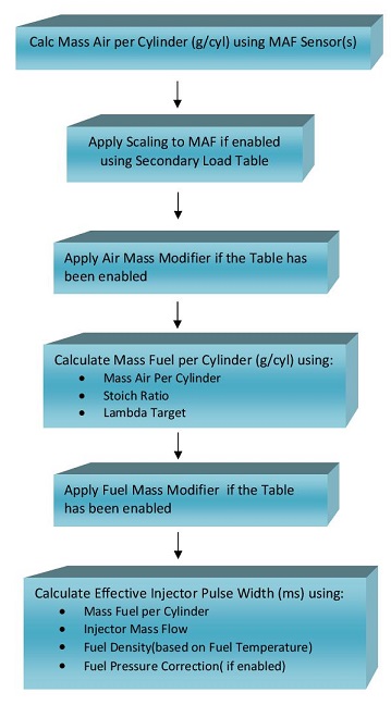
The primary job of the Air Mass Model is to inform the Emtron Fuel Mass Model. The air mass model, coupled with accurate fuel system and injector data allows the ECU to accurately calculate exactly how to operate the fuel injectors to achieve the desired lambda target, even in the most dynamic environments.
Primary and Secondary Injector characterisation with freely customisable 3D Deadtime and Linearisation tables
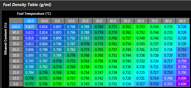
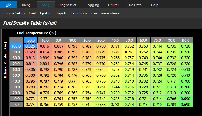
Fuel density modelling, preset based on selected fuel type or custom table
Differential fuel pressure correction – Dynamically recalculates the injector flow based on changes in real-time fuel pressure
2x Lambda Target tables
2x Lambda Target Offset tables
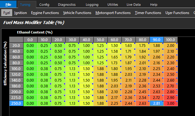
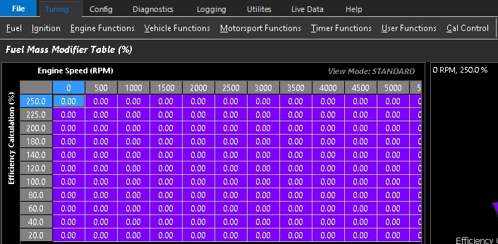
Fuel Mass Modifier Table
Individual Cylinder Trim tables
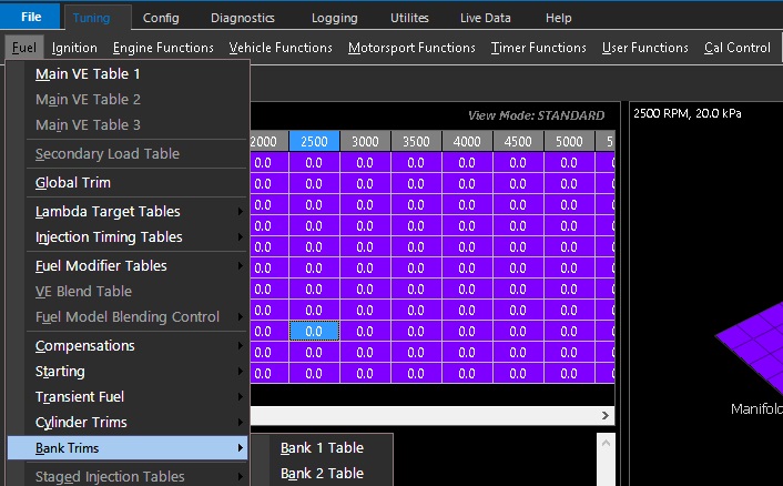
Bank Trim tables
Seamless staged injection blending
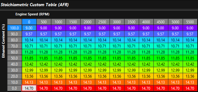
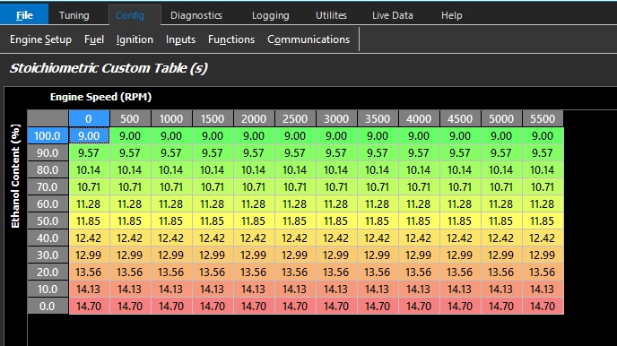
Custom stoichiometric ratio table
Z Axis blending on most tables
Torque Management
Having an accurate picture of air and fuel mass allows the Emtron ECU to accurately calculate real-time engine torque data. There’s no need for lookup tables, torque is mathematically modelled.
Using Throttle Mass Flow, the Emtron ECU can calculate the required air mass for a given torque target, allowing for the kind of advanced torque management required by modern transmissions, as well as a highly refined approach to motorsport functions that are usually achieved with crude cuts and ignition retards.
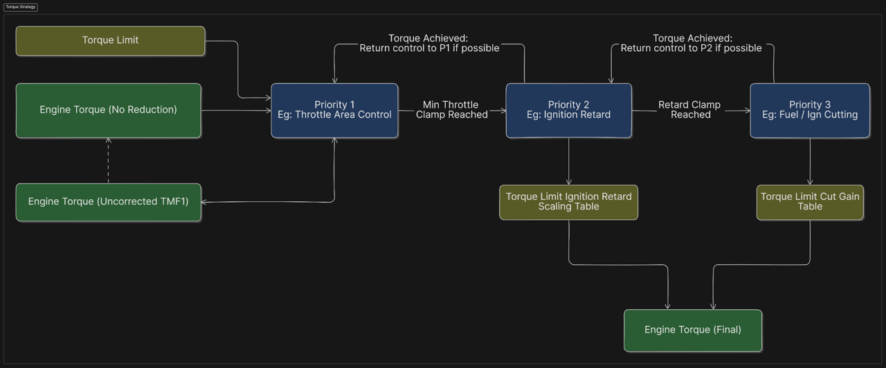
Emtron torque management uses a priority-based combination of throttle control, ignition retard and cutting to achieve and hold a torque target, all parameters of which can be configured. There’s no need to fill in big tables of cut levels or ignition offsets, the torque model will work out what’s required on the fly.
The result is real torque management that is smoother, faster, and better for engine reliability.
Torque based gearshift control for modern transmissions such as the Nissan GR6.
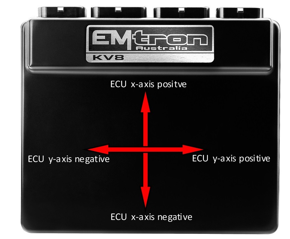
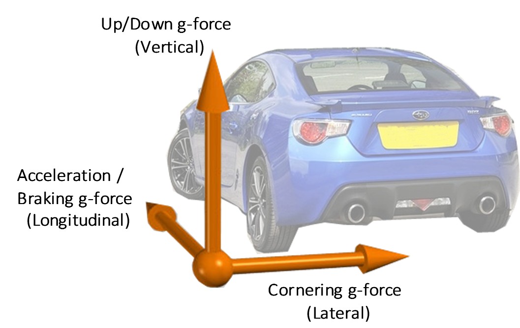
G-Speed (Accelerometer based speed channel for AWD traction control)
Torque Management
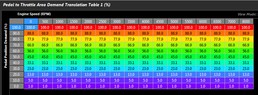
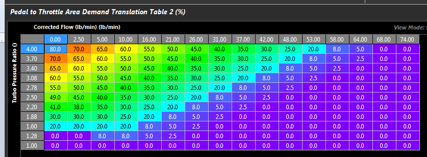
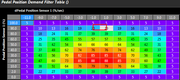
3x Driver Demand Translation tables
Driver Demand Translation Clamp table
Frictional Loss compensation
5x Independent Torque Control Strategies (used by all torque control functions)
Retard Gain
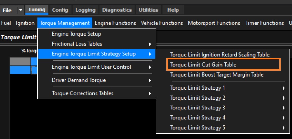
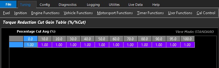
Cut Gain
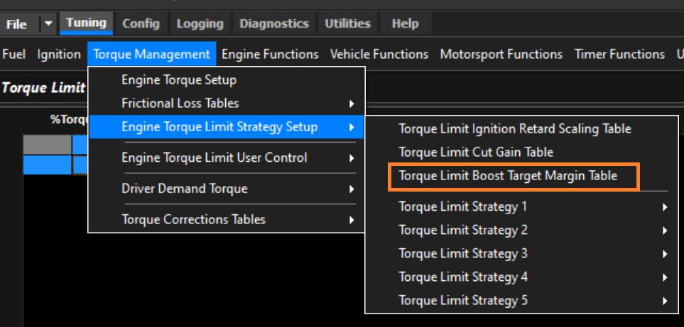
Boost Target Margin Offset
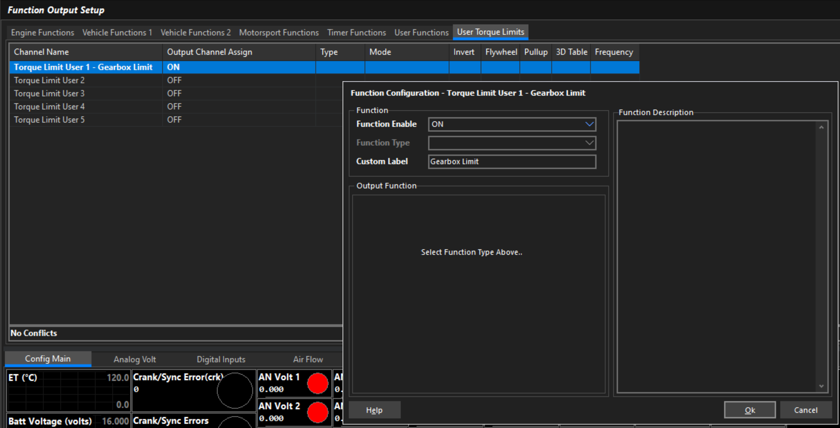
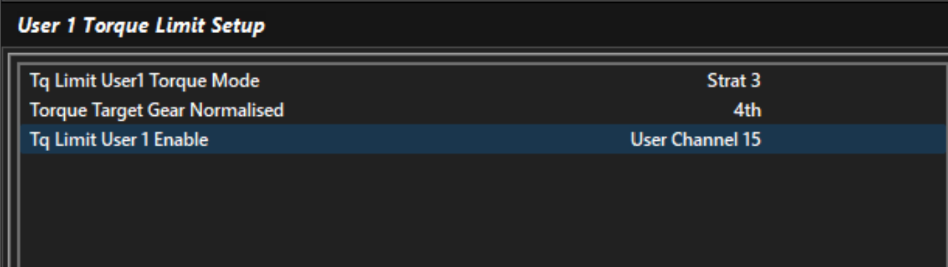
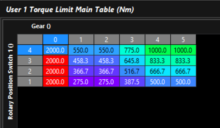
5x User Torque Limits
Selectable Control Strategy
User Channel Enable
Main Limit table
Limit Offset table
Communications
2x CAN 2.0B bus nodes
6x Channels per node
4x User Rx data sets
4x User Tx data sets
70x Preset data sets
Logging
1500+ channels available
Up to 500 Hz
32Mb memory, circular or single shot
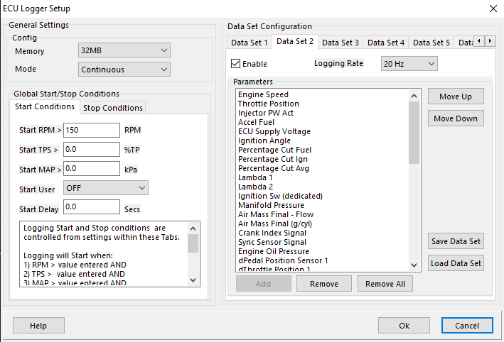
Configurable start/stop conditions
Tune and review data in one place. All logging managed and reviewed inside Emtune, no exporting to other software required.
Trigger Requests
While Emtron supports a high number of trigger types, there is occasionally the need to add new engine types.
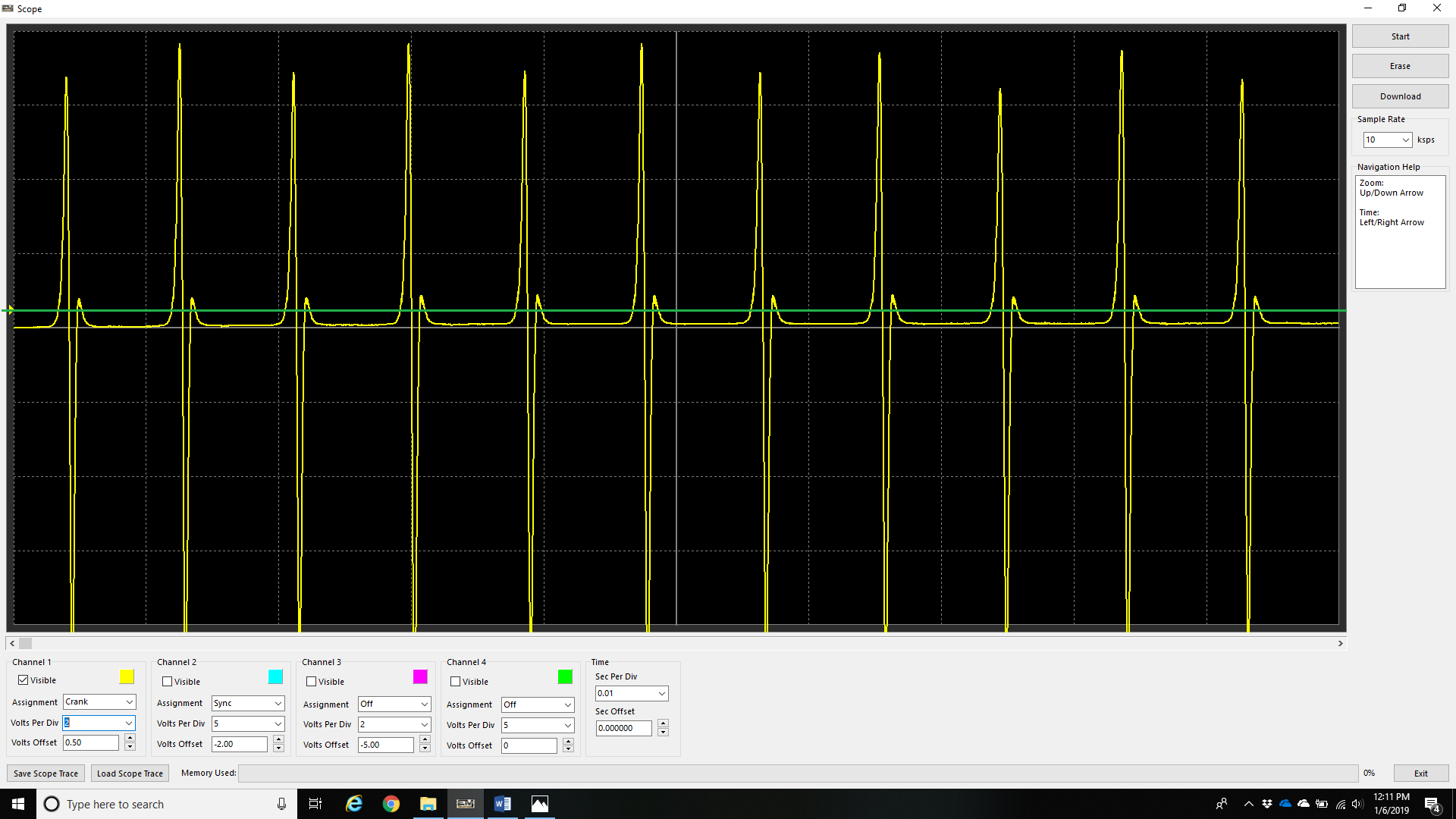
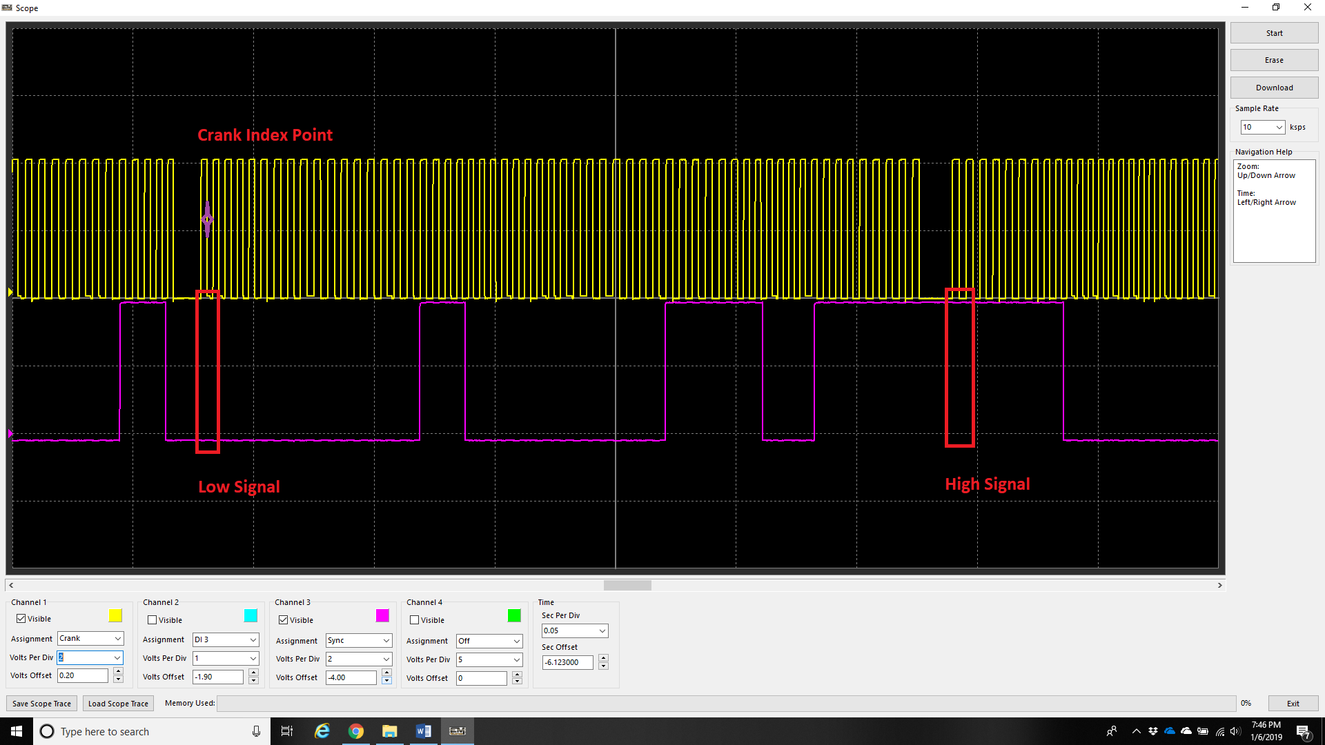
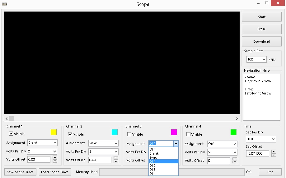
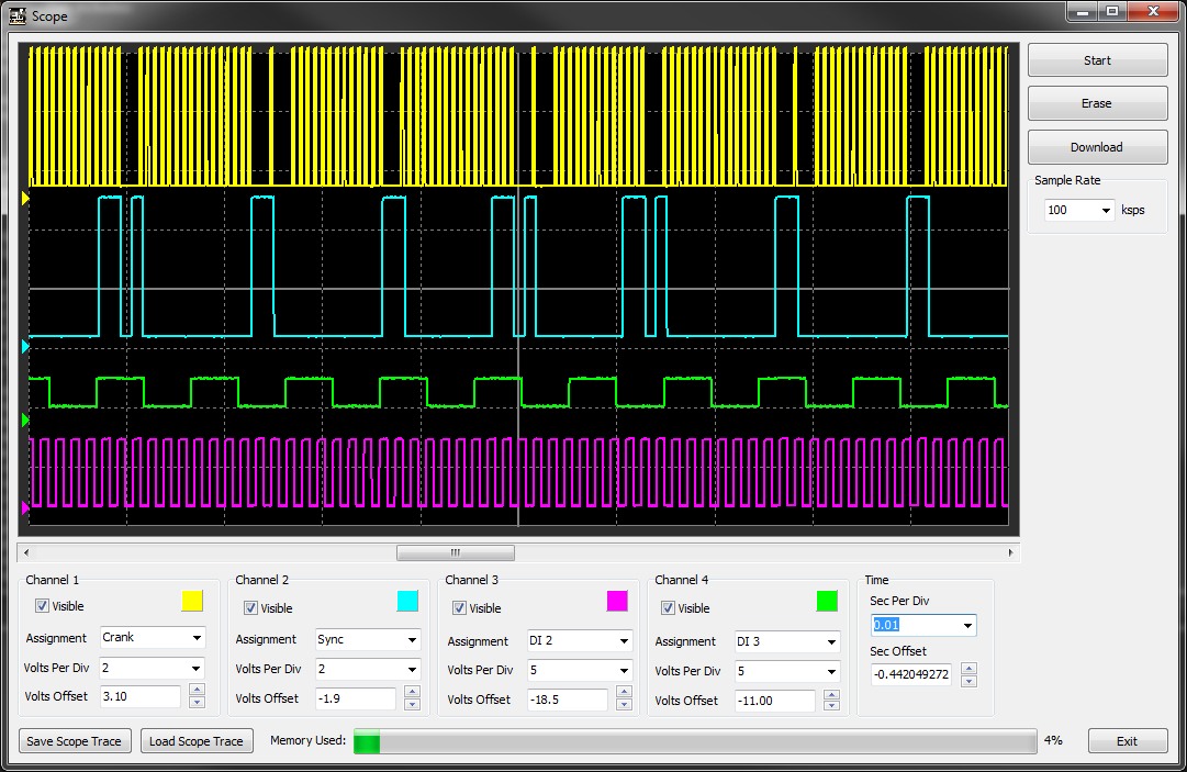
The fastest way to get support for a new engine type is to provide Emtron directly with scope file directly from the Emtune software (exported from the Scope Utility as a *.esf file).
If the vehicle has VVT (variable valve timing), please contact support for any special instructions.
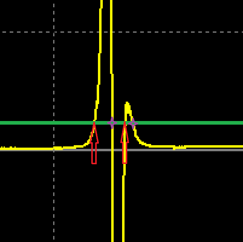
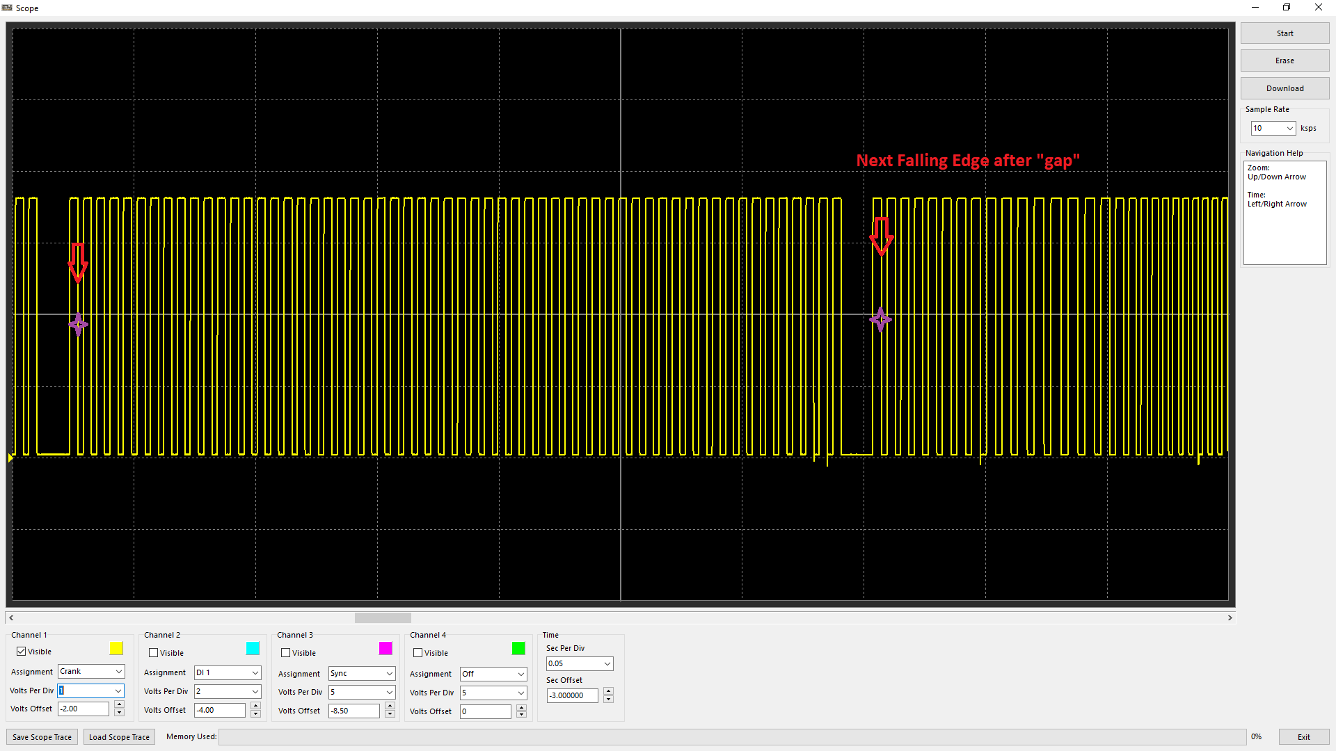
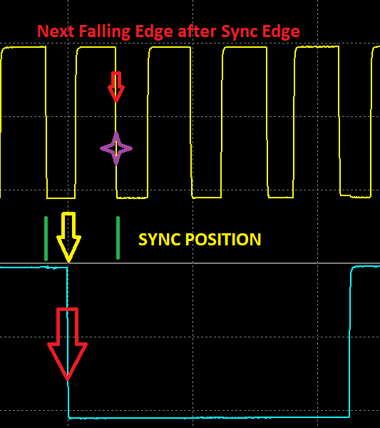
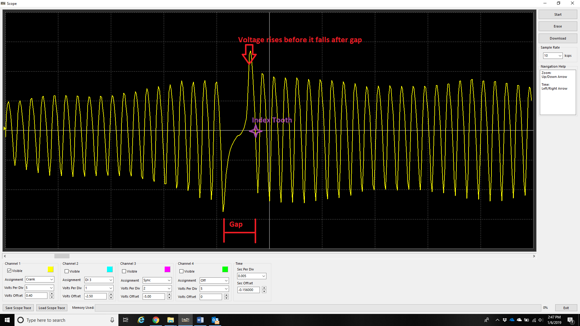
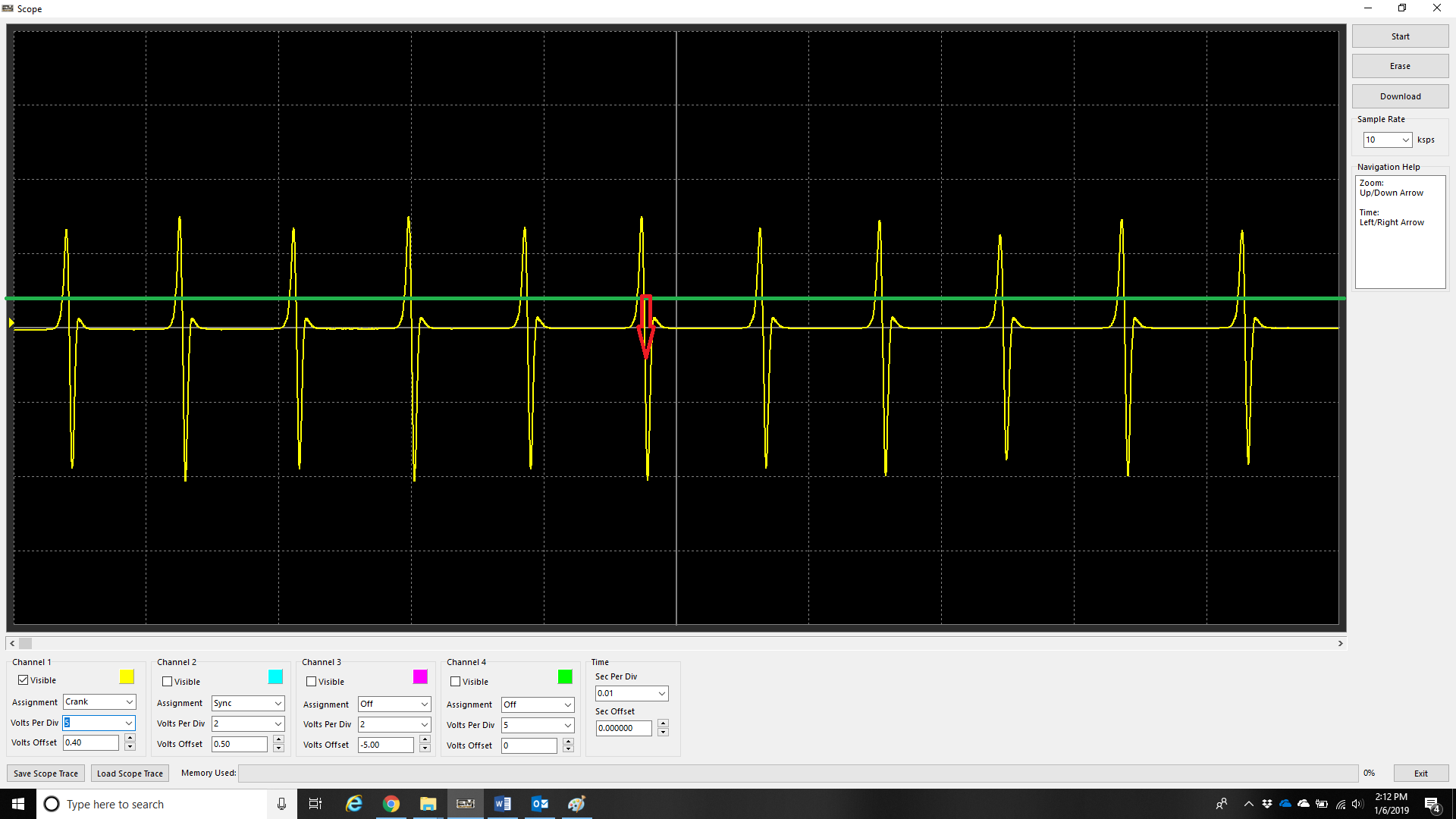
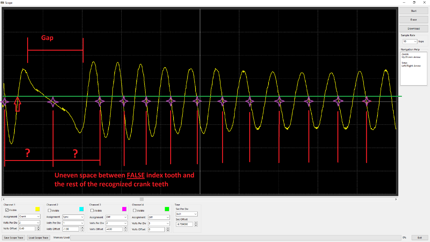
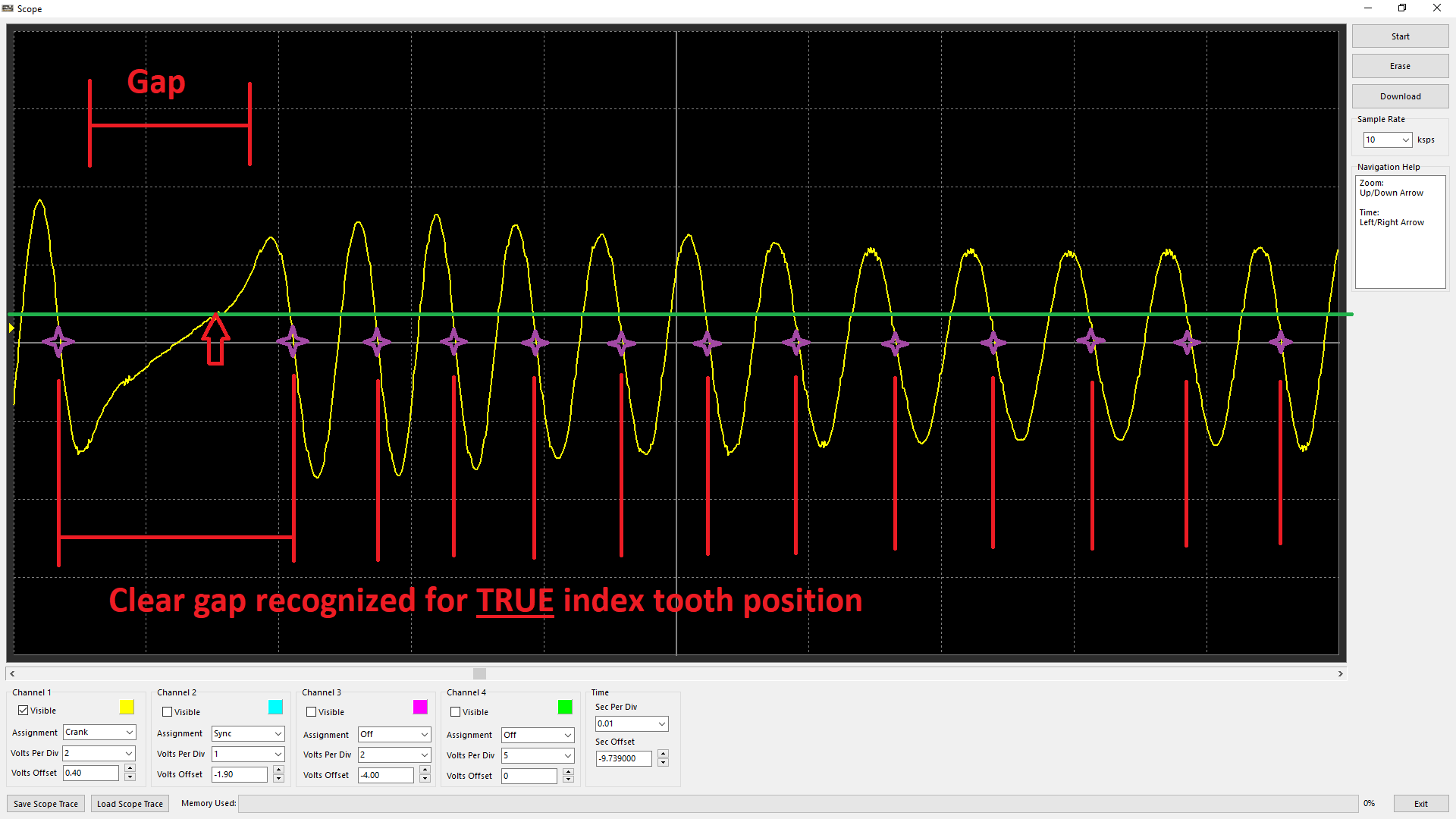
A cranking scope trace with cylinder 1 spark plug removed (or only cylinder 1 spark plug installed) can be helpful in identifying an approximation of crank index offset position. The cranking speed will speed up/slow down at the point of compression.
Read the help, familiarize yourself with the software and don’t be afraid to ask for assistance if you get stuck or are unsure.
Ethernet Connection
Connecting the ECU
Communication Cable
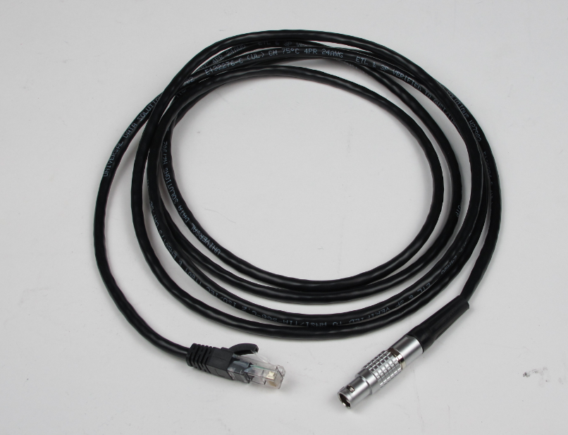
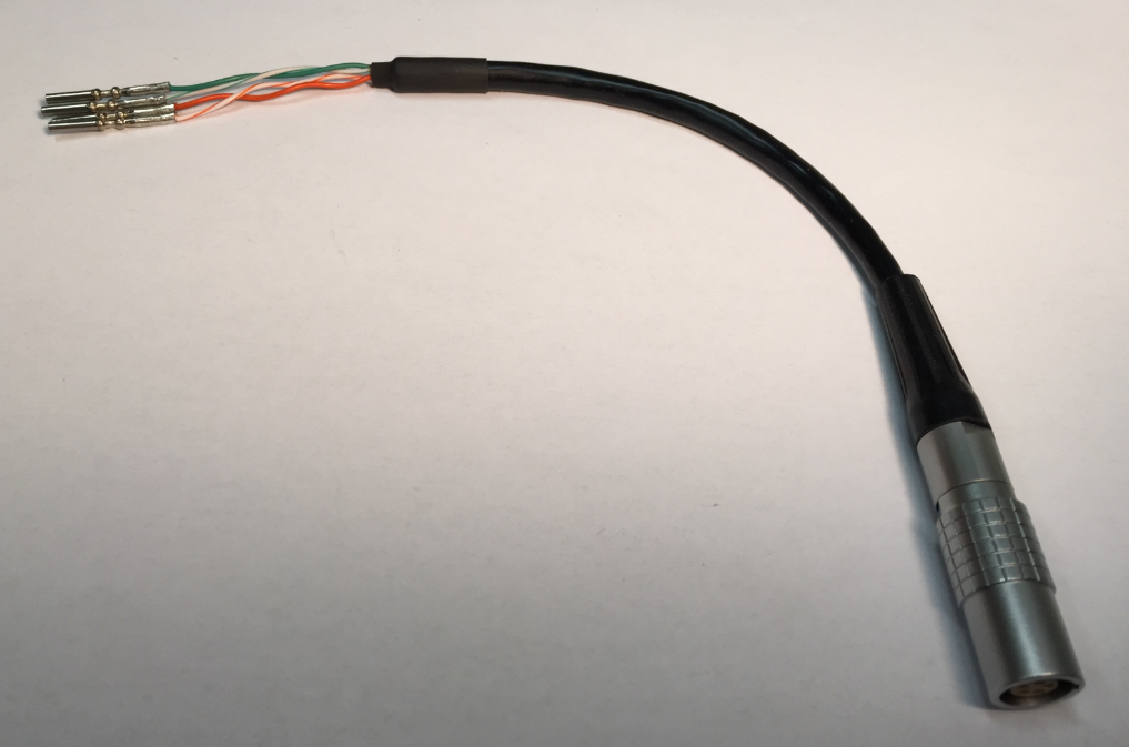
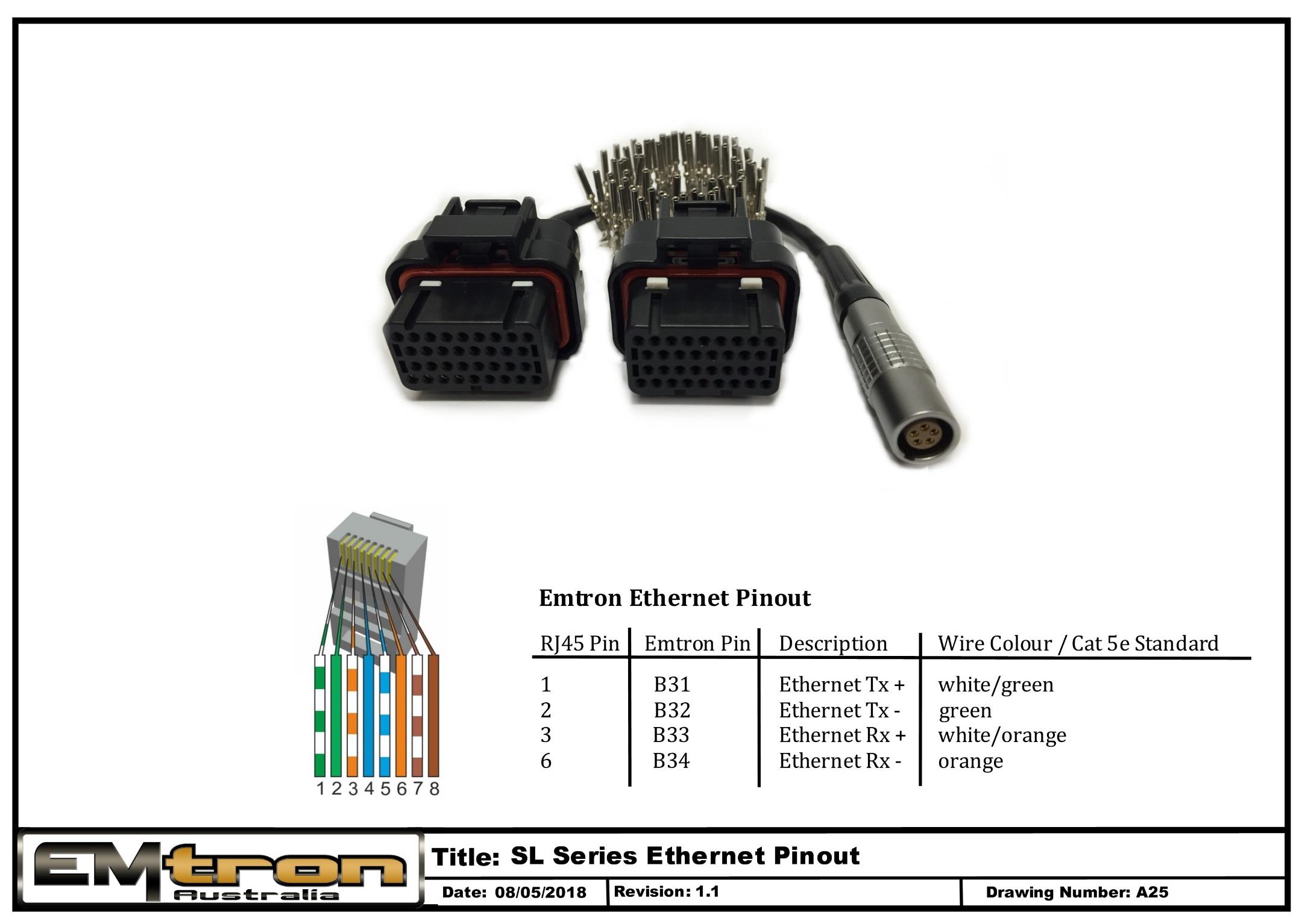
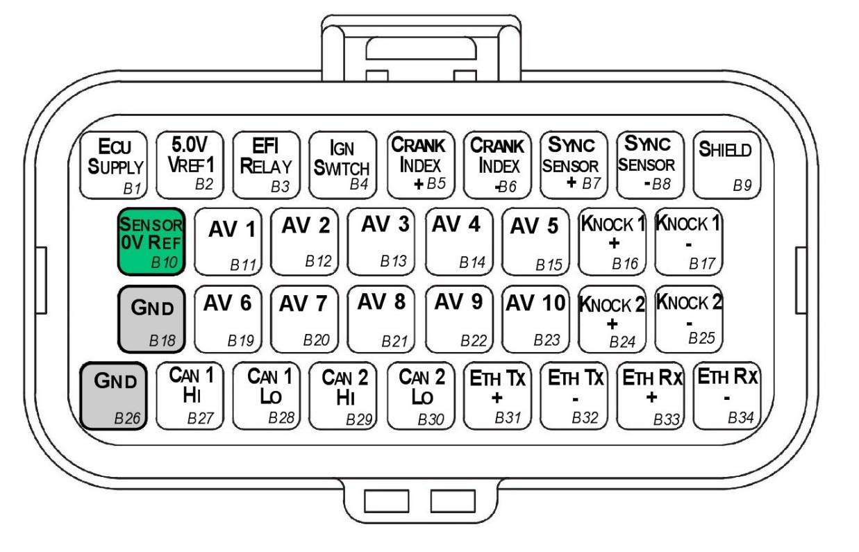
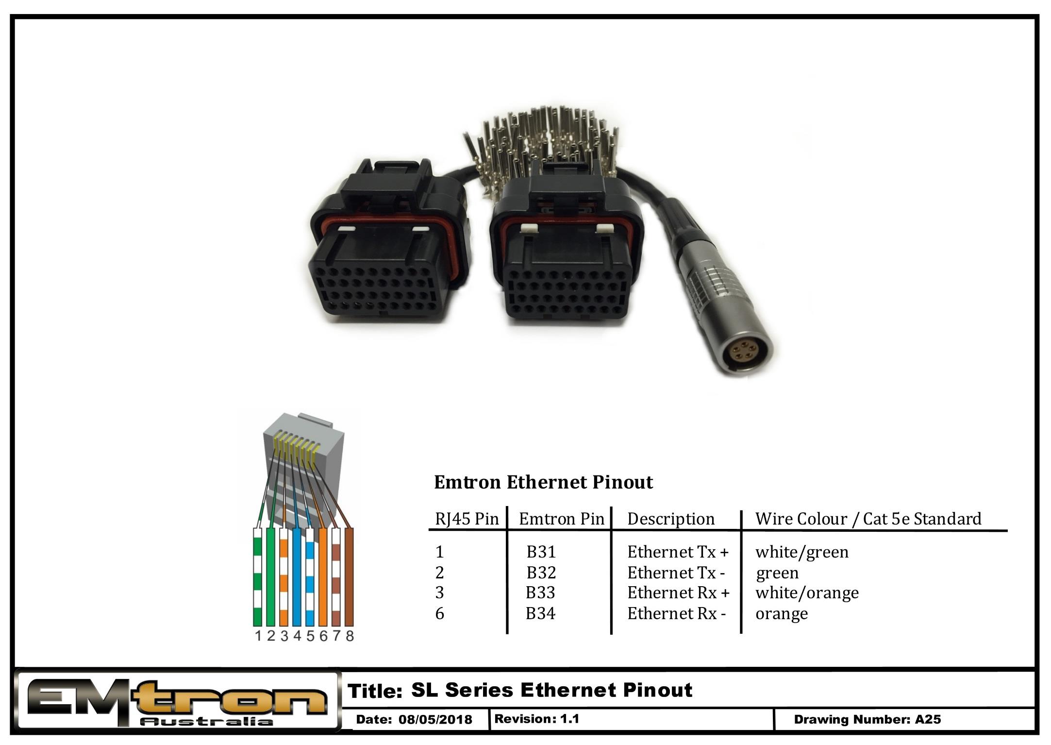
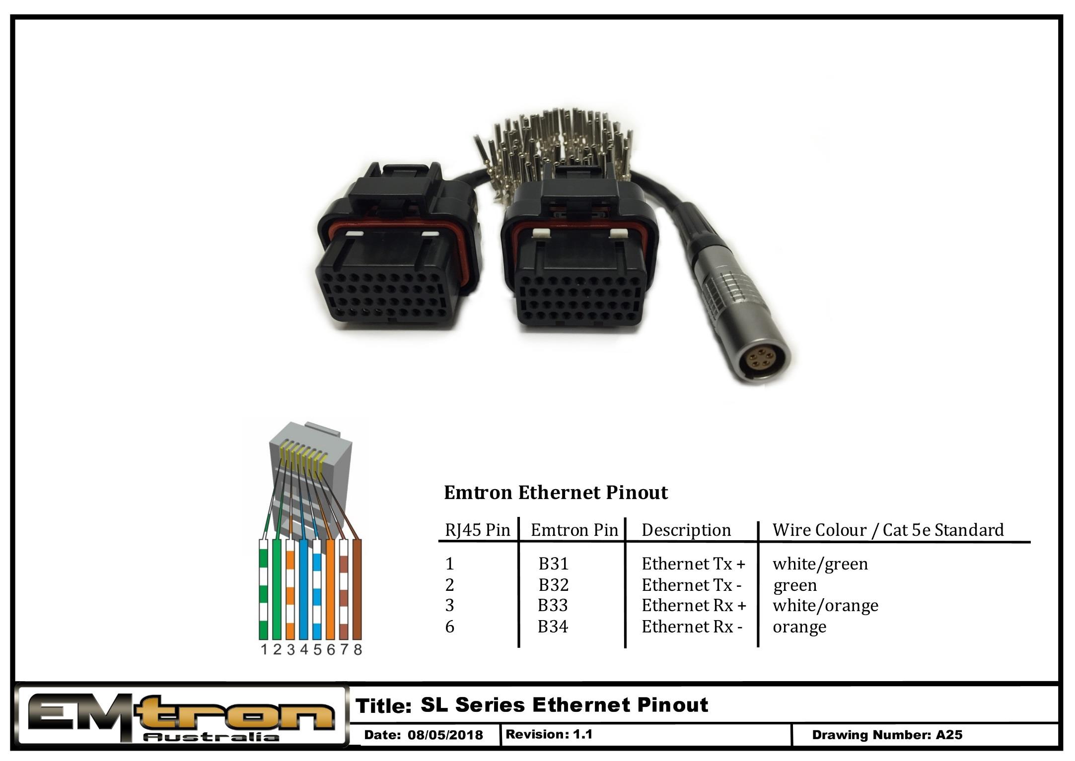
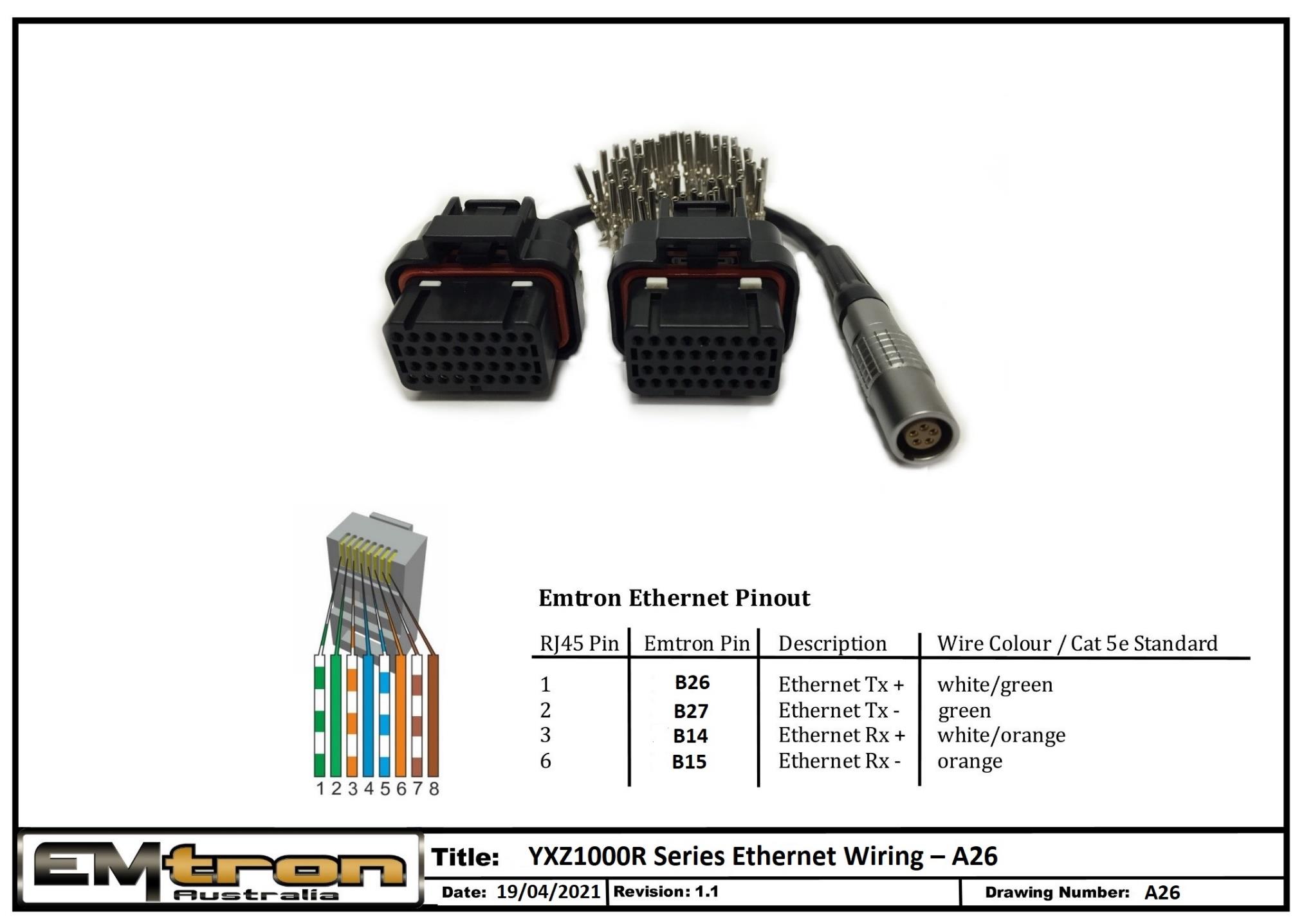
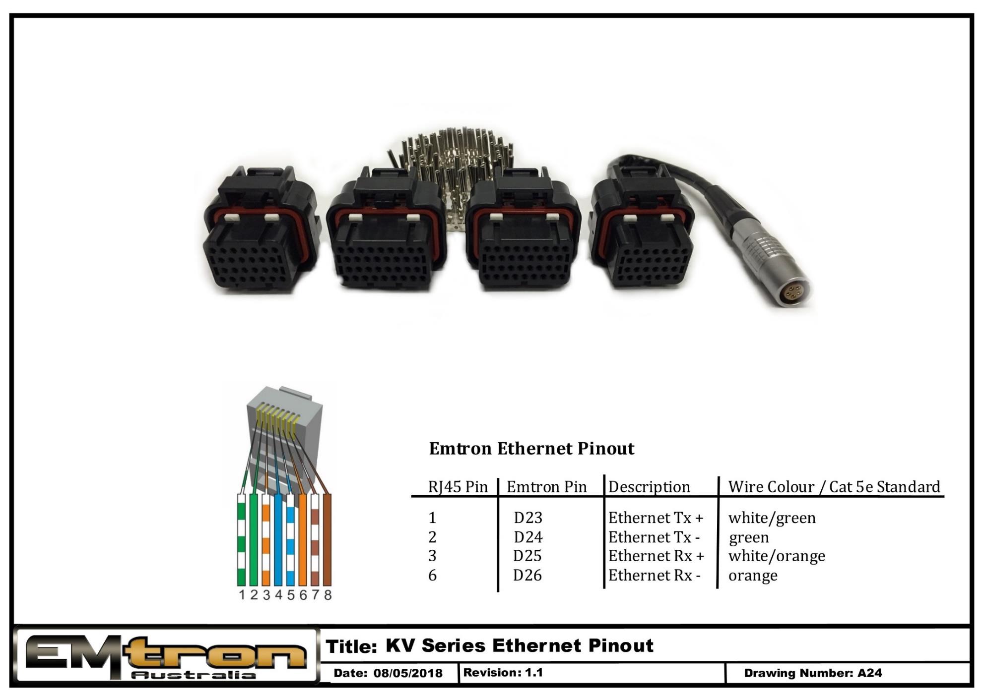
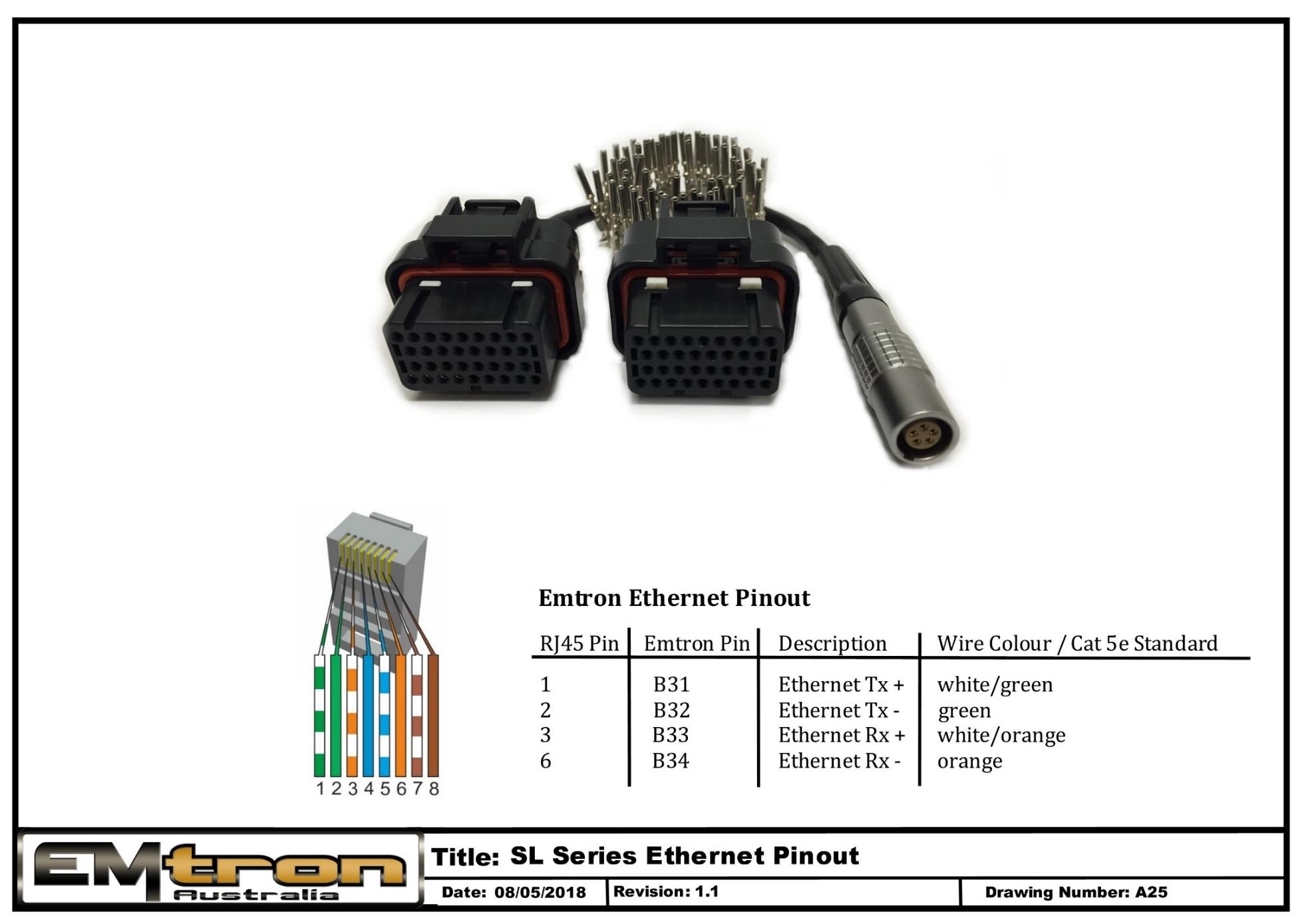
The Emtron proprietary communication cable translates standard high speed Ethernet to a Lemo connector that feeds directly into the ECU header.
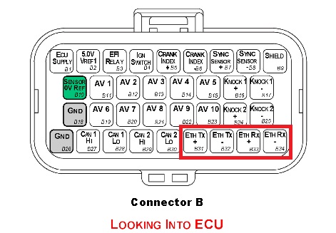
The pin configuration for the Lemo receiver is as follows.
SL series
Wire
SL Pin
Green/White
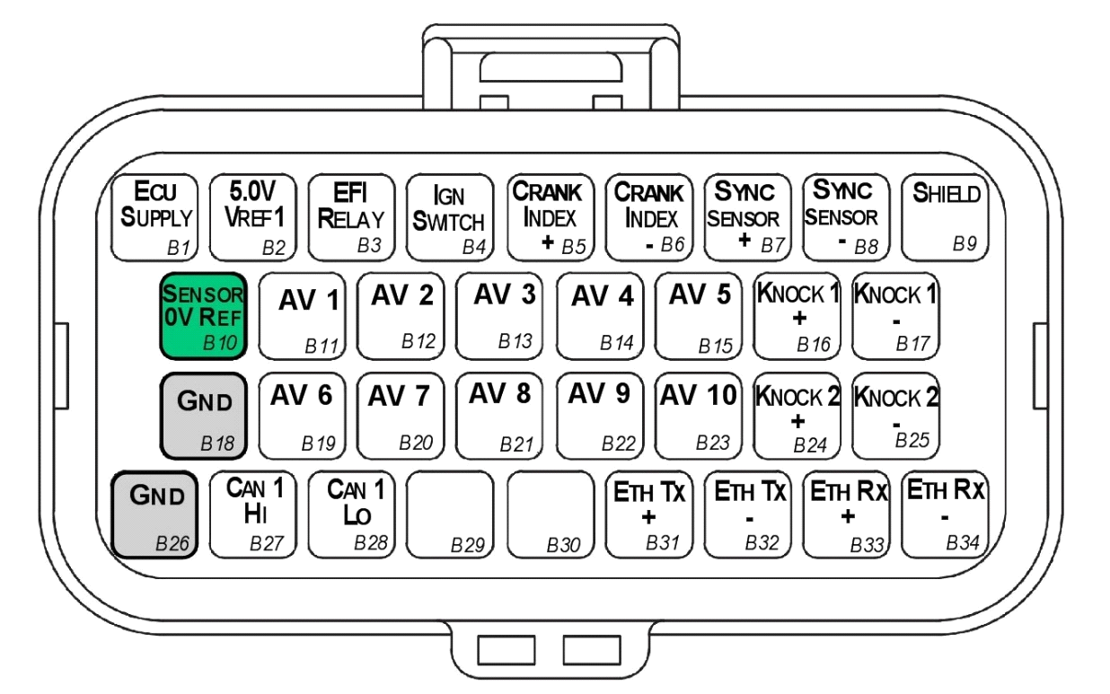
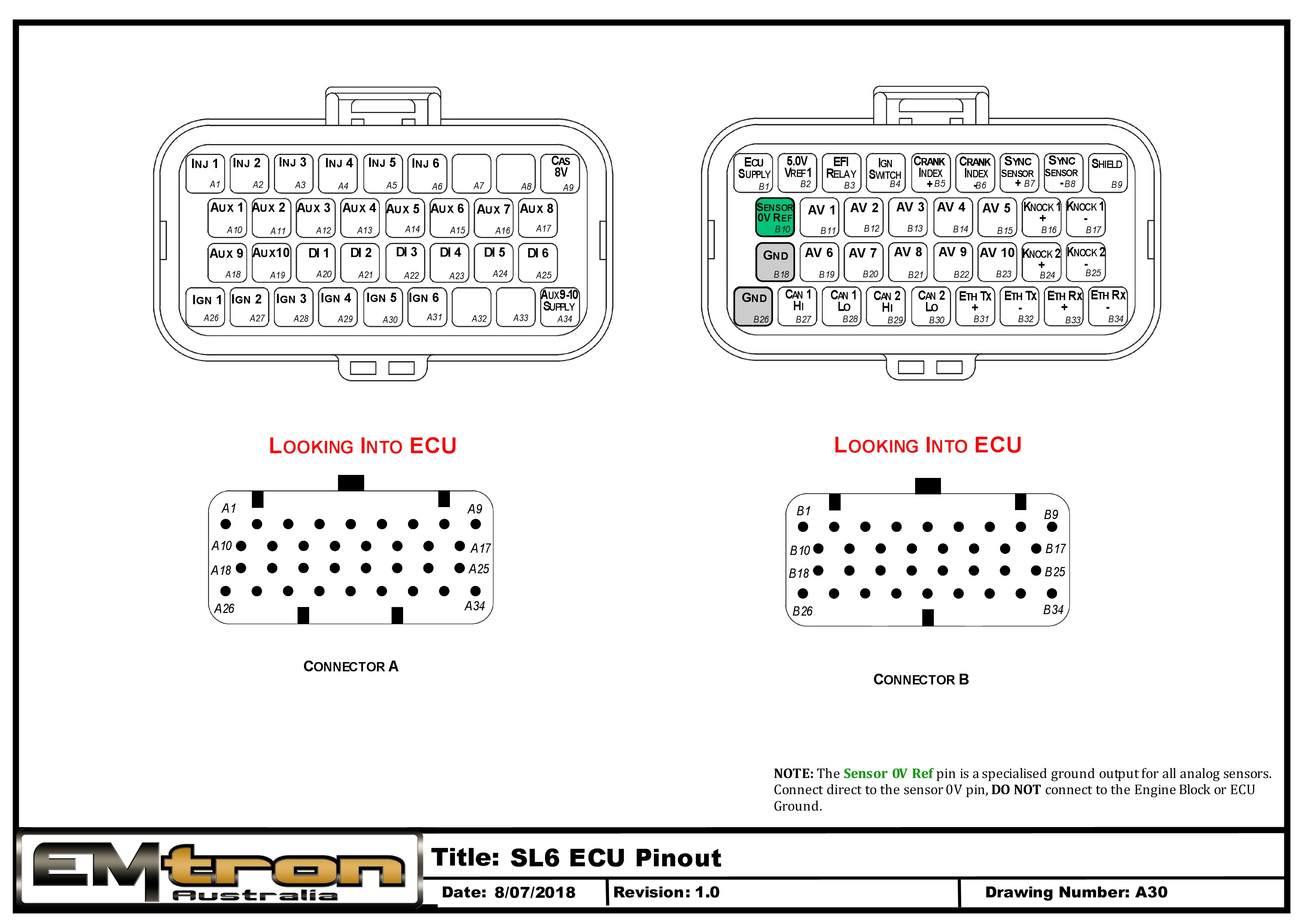
B31 (TX+)
Green
B32 (TX-)
Orange/White
B33 (RX+)
Orange
B34 (RX-)
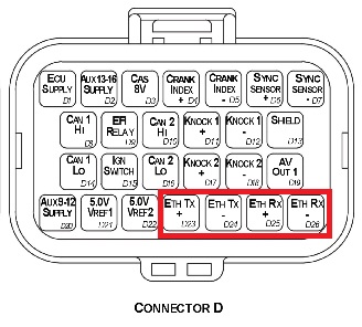
KV series
Wire
SL Pin
Green/White
D23 (TX+)
Green
D24 (TX-)
Orange/White
D25 (RX+)
Orange
D26 (RX-)
IP Config
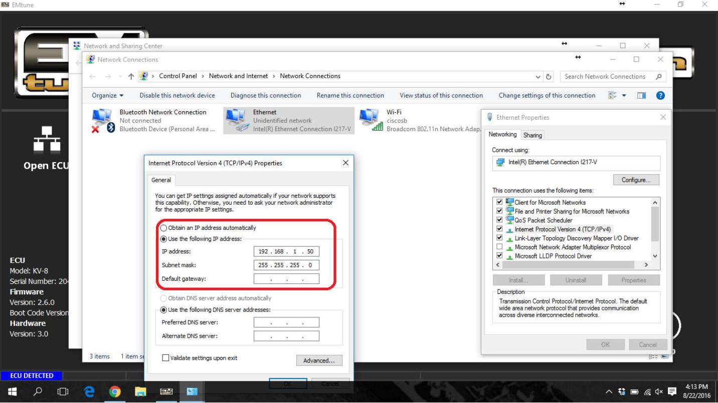
The Emtune software will communicate to the ECU over a static IP address.
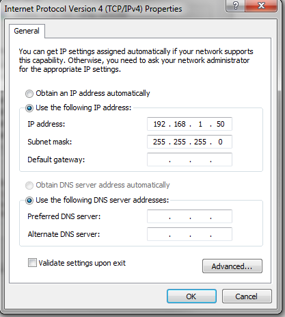
Set your IP and subnet to the following on the Ethernet port you will be using on your PC.
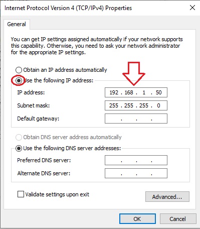
IP: 192.168.1.50
Subnet: 255.255.255.0
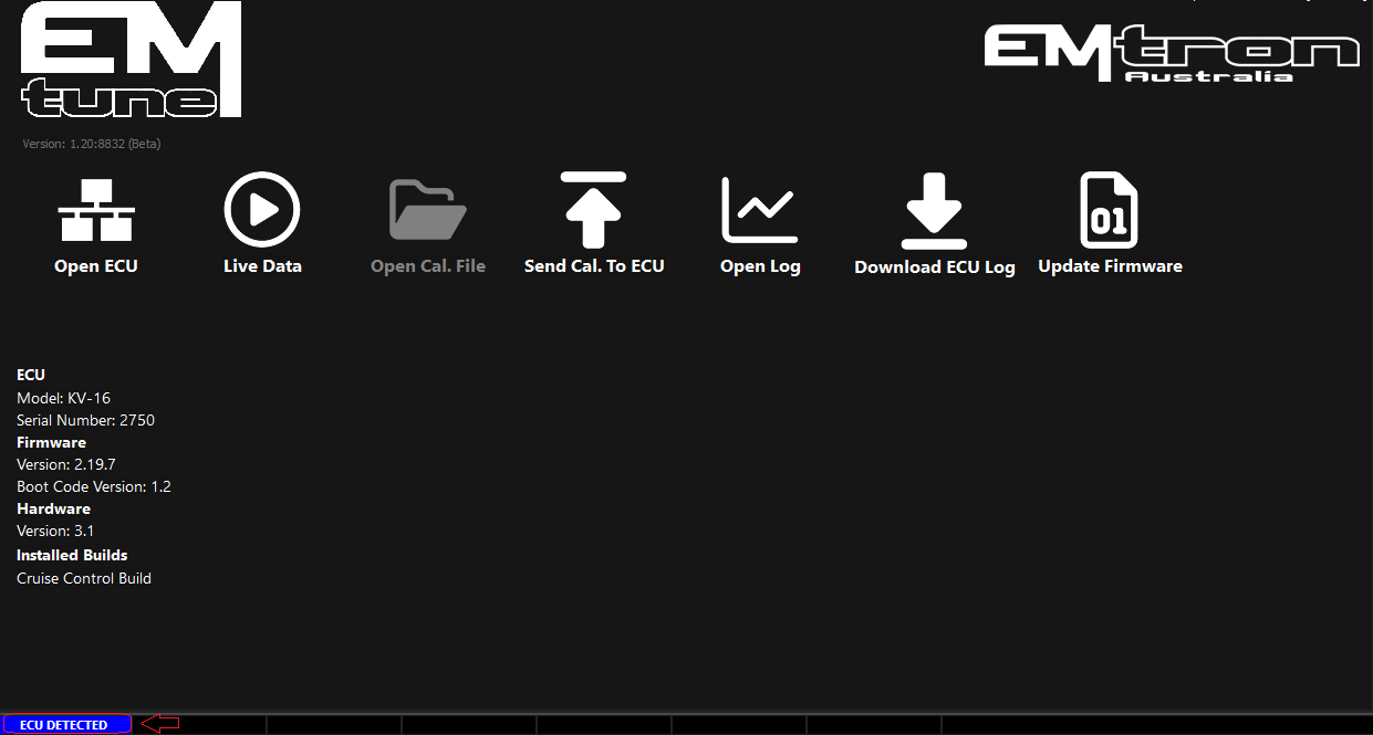
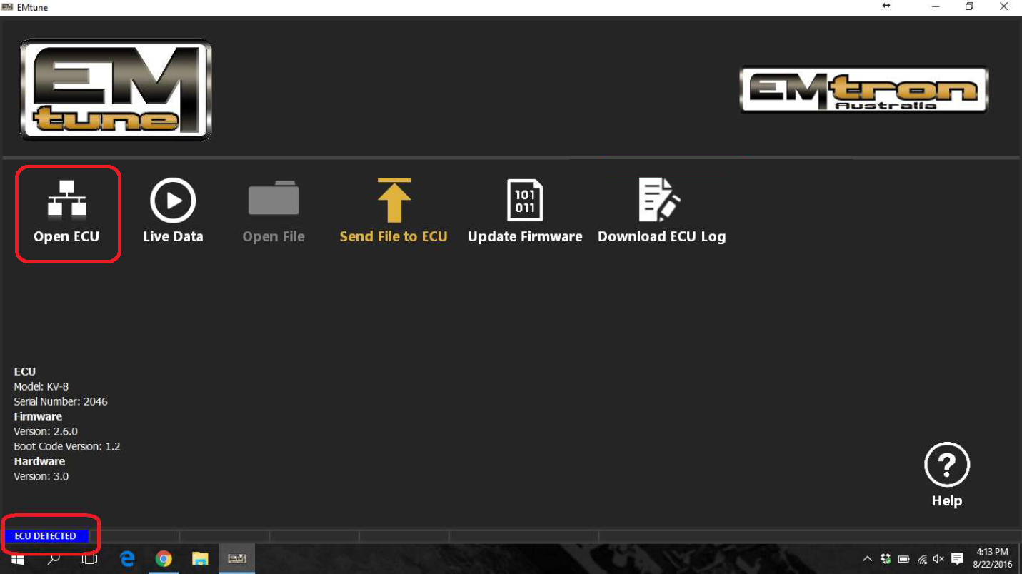
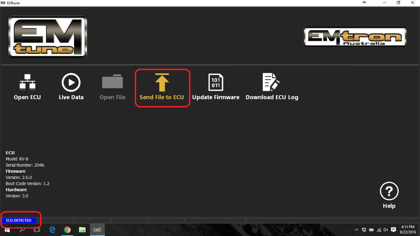
With successful connection, the Emtune Welcome screen will display “ECU DETECTED” in blue in the bottom left corner as can be observed in the background in the above example.
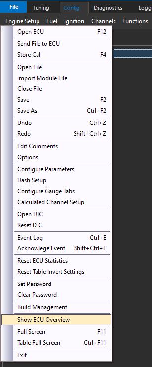
The cal file information such as pin configuration, assignments, and even the FW version can easily be accessed via the file menu under “Show ECU Overview”
Setting Paths
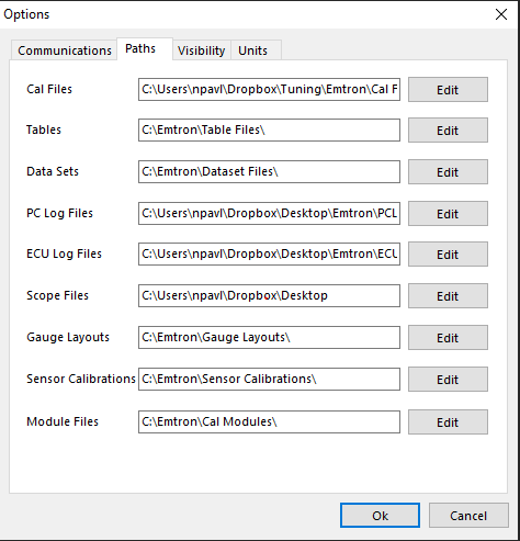
Paths can be reset under the file menu under “Options”.
Unit Preferences
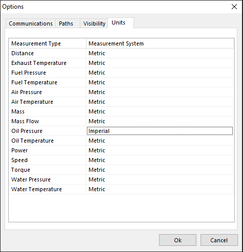
Units can be converted under the file menu under “Options”.
ECU Cal FIle Locking
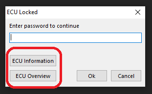
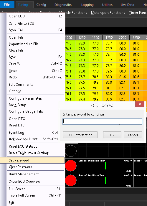
ECU Cal Files can be locked under the file menu (Password protection).
CautionThe ECU cal file cannot be unlocked by Emtron Support for any reason if it is locked, as this is done in the actual calibration file.
The user is free to load in any cal file they please though, including an unlocked cal file (on top of a locked cal file).
Loading in a new cal file will overwrite the cal file loaded into the ECU, so that current cal file will be lost.
If a cal file is locked, Emtune will allow the user to view the “ECU Overview” though to see what the current pinout of the ECU is.
Viewing Runtimes
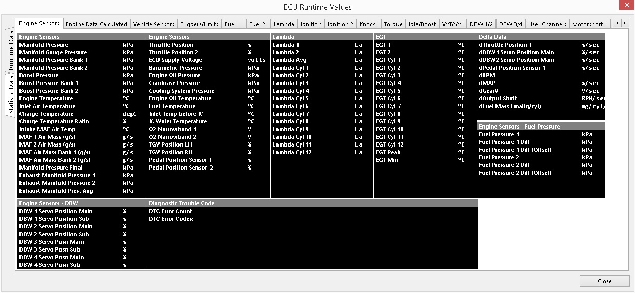
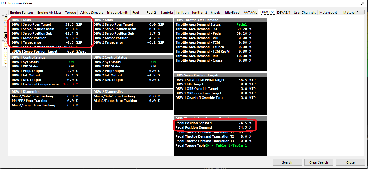
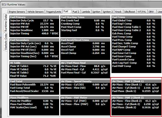
Pressing “F3” anytime the ECU is open will display all calculated channels in real time.
Navigate through the tabs, or “Search” for the channel you are looking to view.
Output Testing
All outputs can be tested in the ECU, and this is a recommended procedure before running the engine and crucial components for the first time.
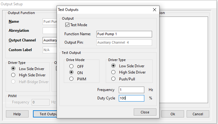
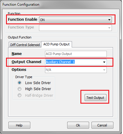
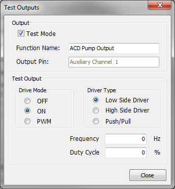
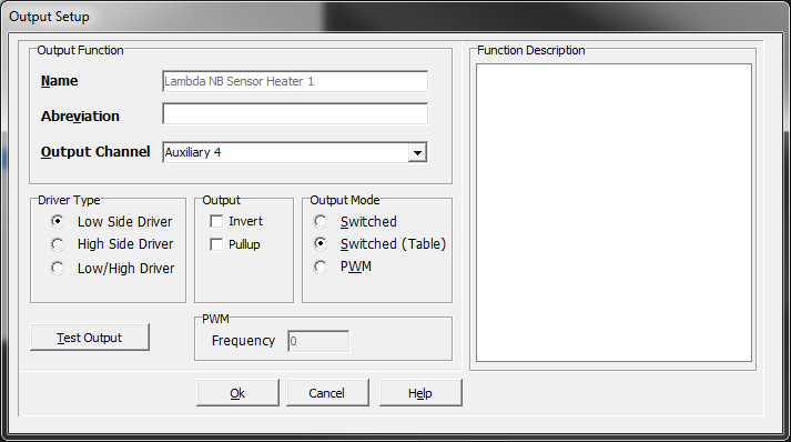
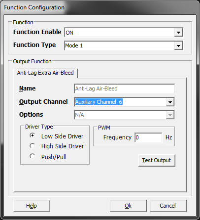
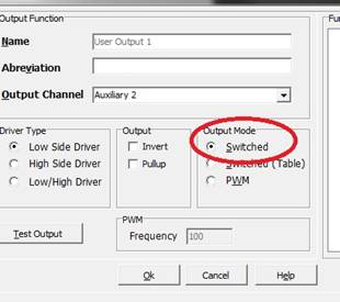
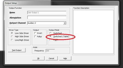
Outputs controlled by functions, can be tested right from the function output setup. The “Test Output” button brings you to this section, where you can set conditions for the output test :
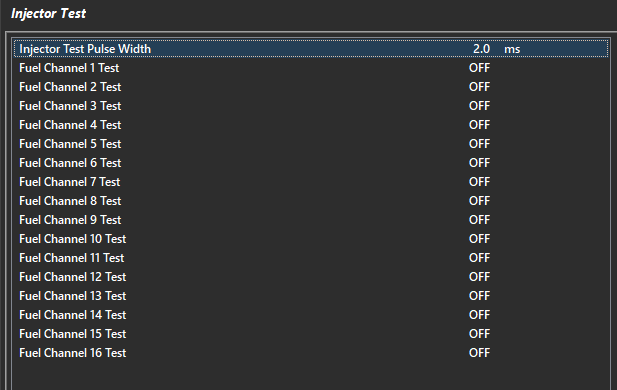
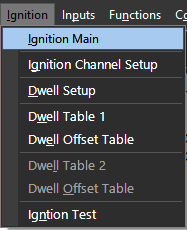
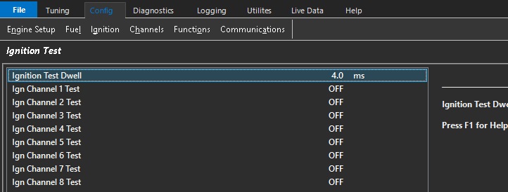
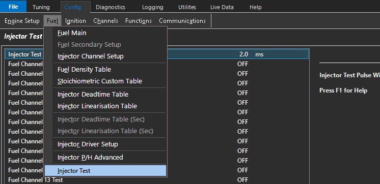
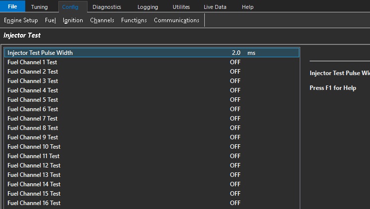
To test fuel and ignition channels, this is done under Config Fuel/Ignition > Injector/Ignition Test
Set the pulse width/dwell for the test, and then turn the channels on to test.
CautionDo not test channels with the engine running
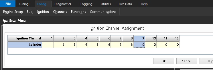
Note: The channels are the actual channel assignments from the ECU, and not the cylinder assignments - IE if you have cylinders assigned on different channels, they will NOT correspond during this test.
Starting Engine/No Start
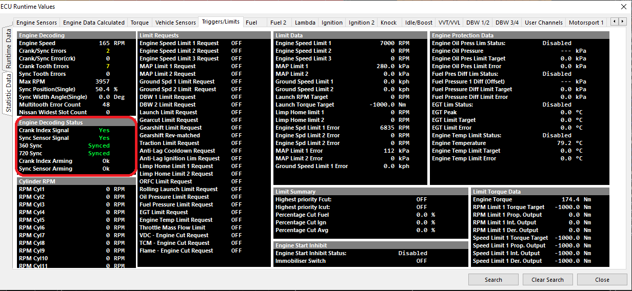
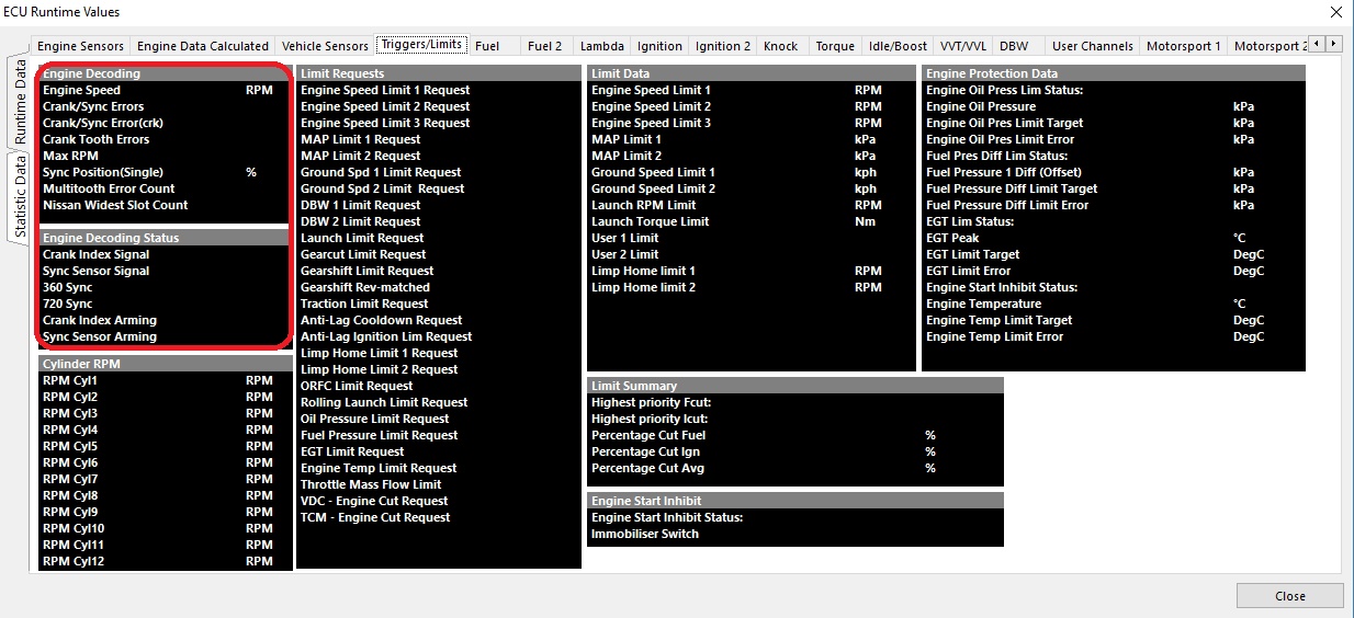
Once configuration is complete, startability of the engine can be observed (and logged) in Runtimes view (F3) under Triggers/Limits > Engine Decoding Status.
For sequential configuration, Crank, Sync, 360, and 720 sync must all go “Green” in order for the decoding to be satisfied and the engine startability to be achieved.
Tip Engine Speed should be observed cranking as well
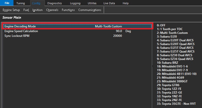
On universal configurations such as “Multi-tooth Custom”, if the engine will not start, the stroke for sequential firing may be on the wrong phase.
An easy way to correct this is to add 360 degrees to the Crank Index Offset value.
Engine Limiting Active
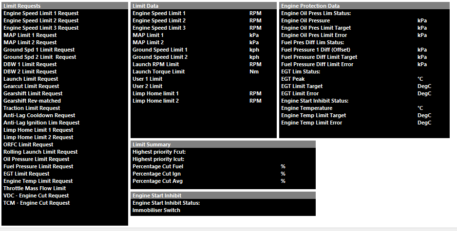
The Emtron ECU can perform a number of different limit types. View what limiters are active in Runtime view (F3) under Triggers/Limits.
Limit Requests will show the specific limiter active
Under Limit Summary, Highest priority Fcut/Icut Status will also show the current limiter active (by priority of cut %)
Tip: Highest priority cuts are recommended to always be logged.
Trigger Errors
The following Error channels are calculated in the ECU.
Crank/Sync Errors - This is a counter that will register if the ECU sees an issue during an engine cycle where the Crank Tooth and Sync Tooth are not legitimate.
Crank/Sync Errors(crk) - This error is the same as Crank/Sync Errors but occurs inside the Cranking Speed entry window (Crank RPM Entry and Crank RPM exit).
Crank Tooth Errors - This is a counter that will register if the ECU sees the incorrect number of expected count of crank teeth during an engine cycle.
Sync Tooth Errors - This is a counter that will register if the ECU sees the incorrect number expected sync teeth during an engine cycle,
InfoAll trigger errors when they register will result in engine misfire as the ECU will attempt to abort running the engine for that cycle (cut). This is to prevent the engine from running improper timing or improper cycle.
Data Logging/Diagnostic Tips
Crank Tooth, Crank/Sync, Crank/Sync(crk) counting during engine cranking/low battery voltage sometimes can be considered normal depending on the trigger type, tooth count, engine compression ratio, etc.
This is due to the ECU attempting to scrutinize the trigger accurately during cranking, missing teeth, crank index teeth, etc.
Crank Tooth Errors alone usually mean the main Crank Index Signal has issues
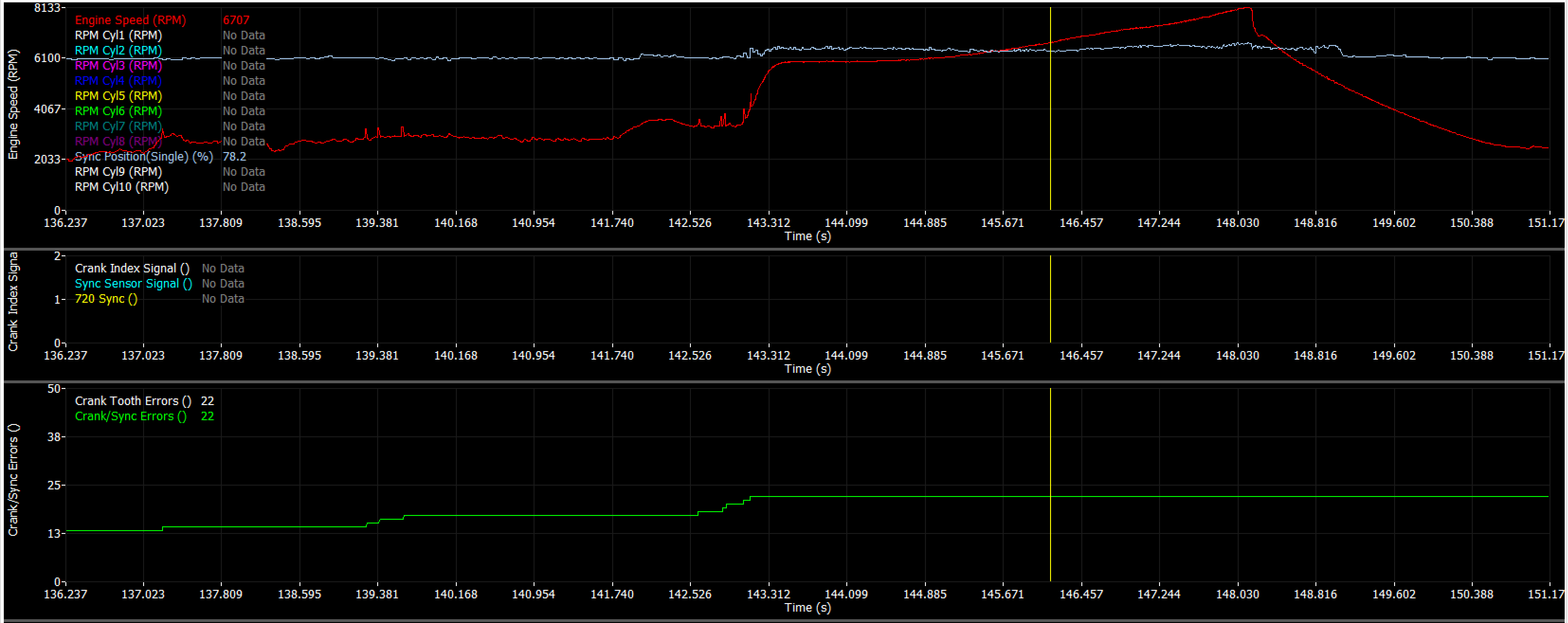
Crank/Sync Errors alone usually mean there is a Sync Sensor Signal issue.
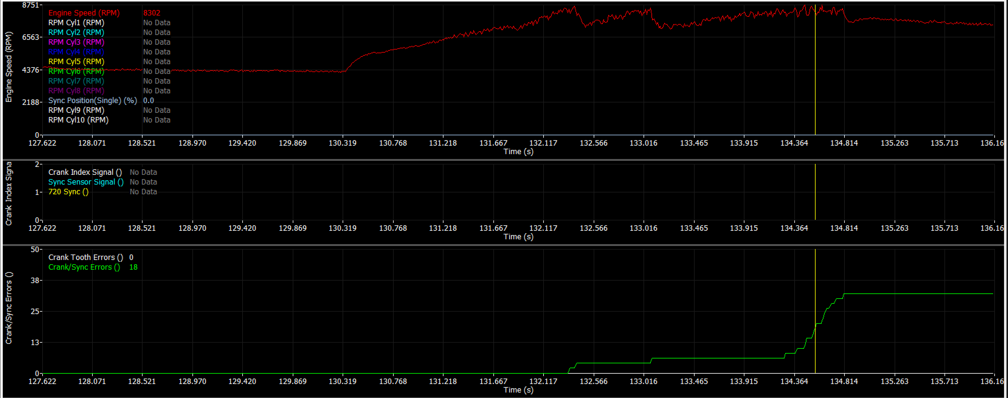
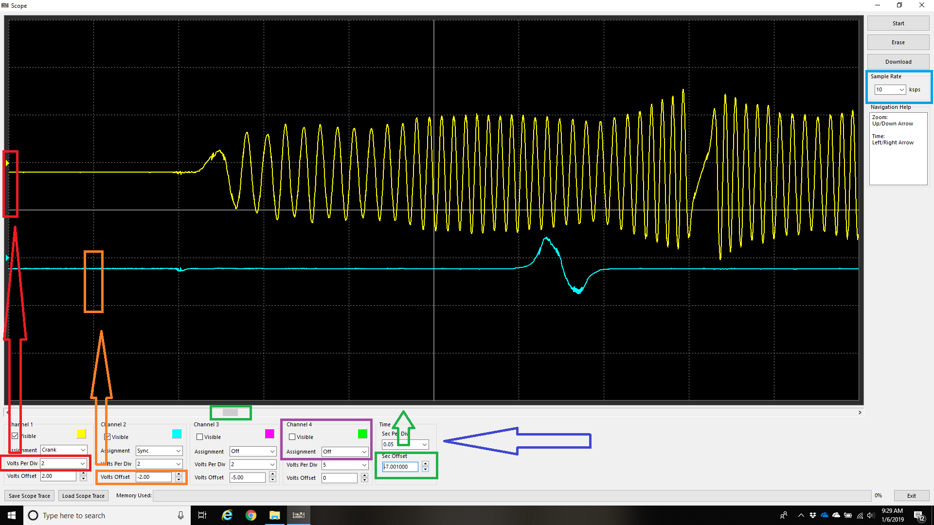
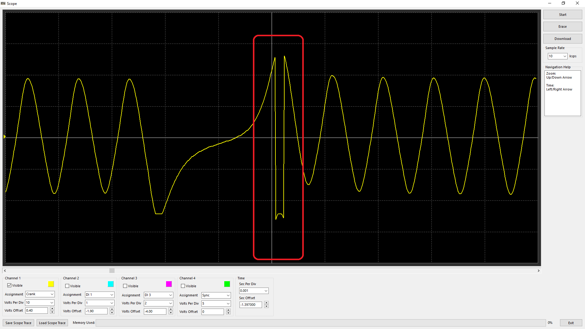
Crank Tooth Errors AND Crank/Sync Errors usually mean there is interference/rouge on one or both of the main trigger inputs. Investigate the Sync Signal first with the ECU Scope.
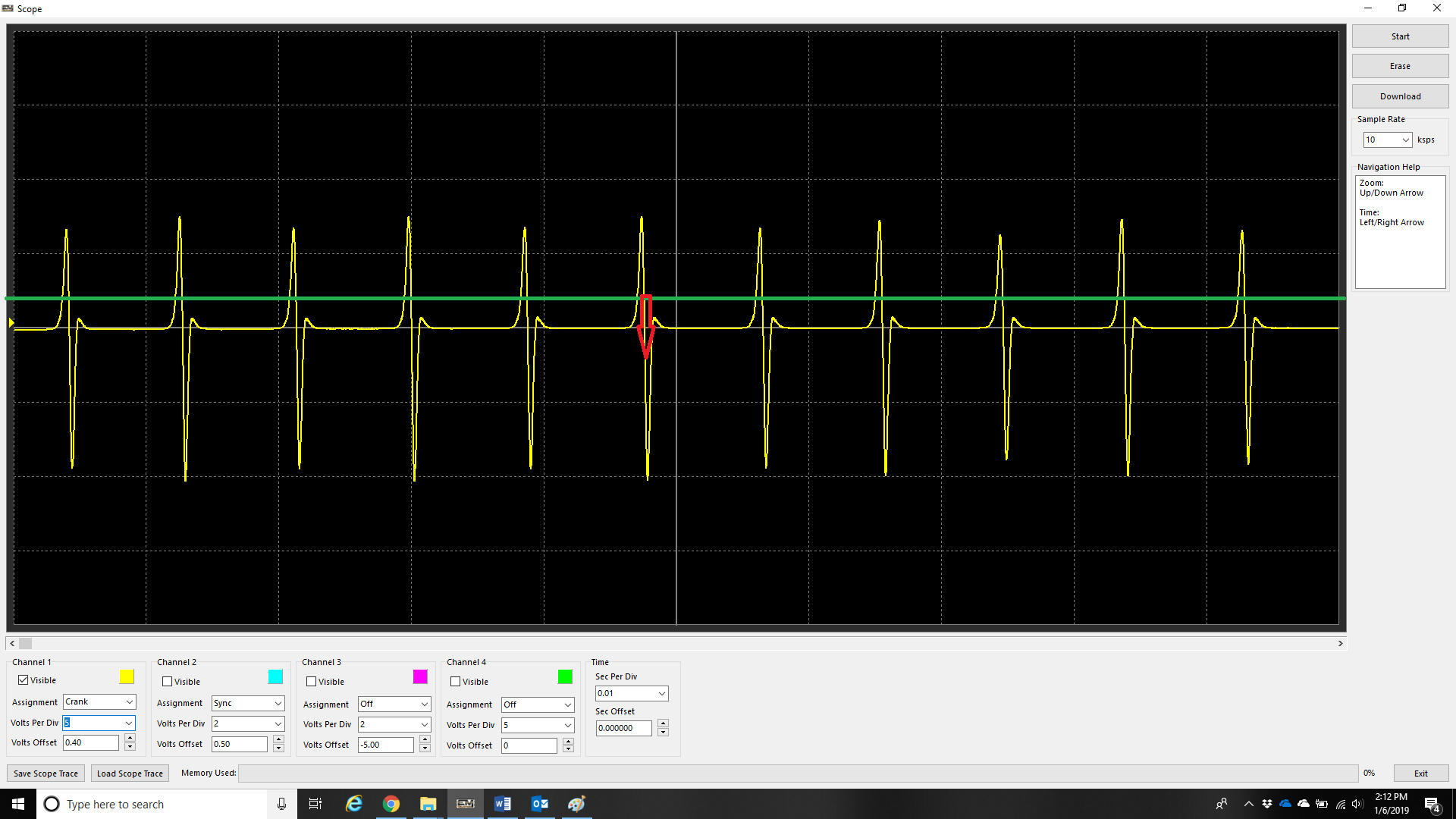
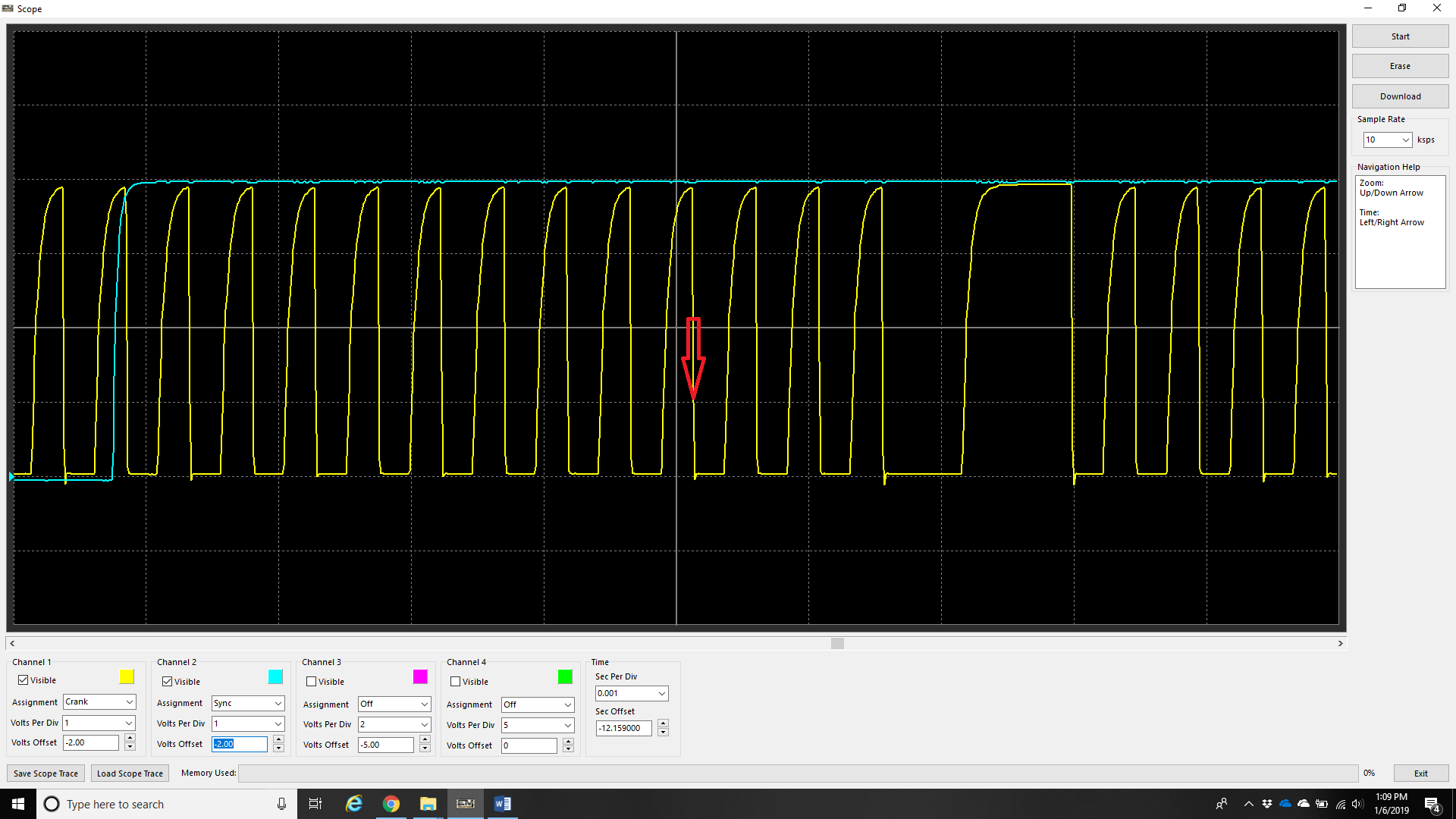
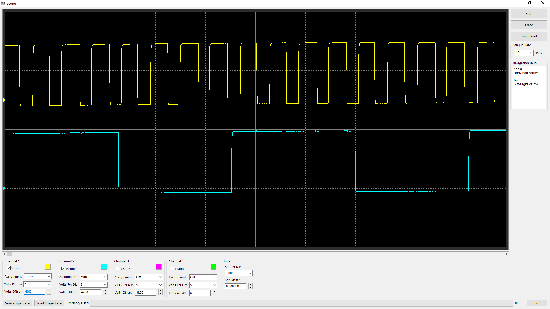
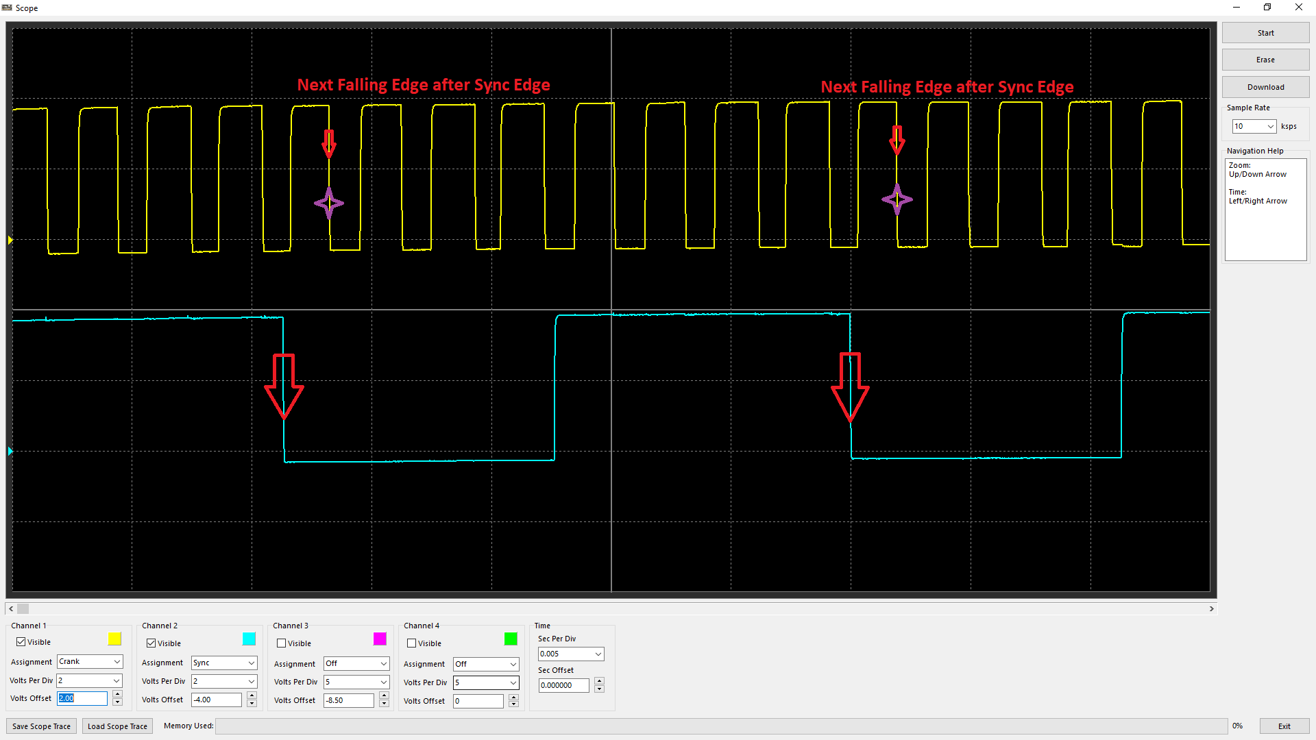
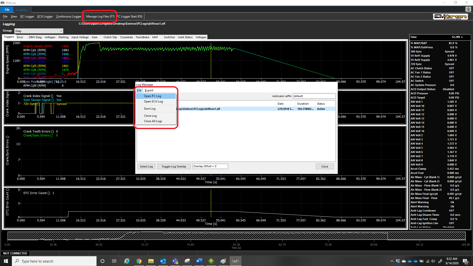
Example of vehicle with failing Sync sensor signal.
Example of vehicle with rouge sync sensor signals (triggering both crank and crank/sync tooth errors together).
Support
What is included, and what kind of support should be expected from Emtron?
Emtron provides worldwide technical support to our dealers and customers, with support staff located around the globe for fast response regardless of your time zone. Our team includes expert calibrators, who have worked on countless applications and engine configurations, and have a comprehensive understanding of the Emtron hardware and software product line to help answer your questions and troubleshoot issues.
While our support staff are absolutely here to answer questions, support hardware issues, and help point you in the right direction - for a wide variety of reasons, unfortunately our staff cannot tune customer vehicles, provide more than basic base/start up maps, or teach fundamentals of engine tuning or even basic fundamentals of the software. Emtron software and hardware is incredibly capable and sophisticated, but deserves some dedication and time to learn and understand full functionality.
Emtron support is here to guide experienced tuners in the use of the hardware and software, as well as to ensure there are no problems with the hardware or software. Emtron provides training sessions around the world annually and we encourage all dealers and self-tuning end-customers to sign up for these events. In addition Emtron recommends EFI University’s series of classes particularly those focused on the use of Emtune software. Furthermore, Emtron’s dealer network consists of some of the best tuners in the world - for end-customers seeking one-on-one support and training in the product, we strongly suggest you contact Emtron dealers in your geography to see how they can help you achieve your goals.
How to contact support?
All support requests are fed into a ticket system, and requests should be made simply by emailing support@emtronaustralia.com.au
Phone Support
Australia: +61 9679 8979
USA: +1978 364 3510
What to include in your support requests
Cal File and Logs: 9 out of 10 times, support staff will need to review the working calibration file and any log file of the conditions in question.
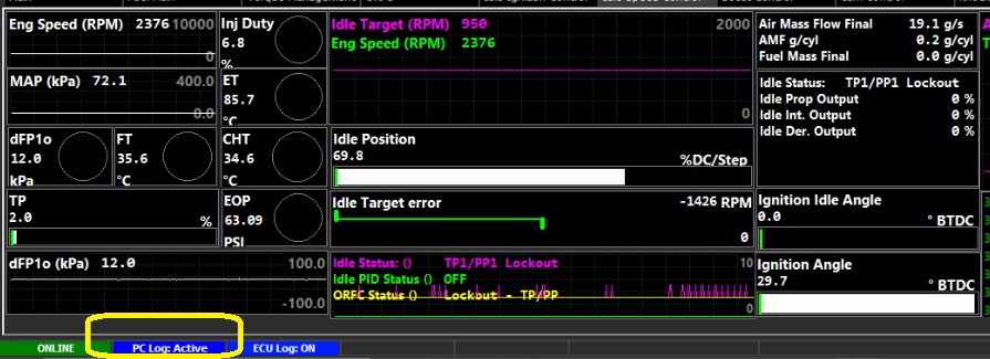
PC logging is the best way to capture the log, as it will record all channels for the staff to review.
Locked Cal Files
If calibration files are locked, our support staff will NOT be able to unlock them. Please provide the password for the cal file in the request, or send unlocked versions of the cal file.
Our support staff do not further record, database, or share any users cal files, passwords, etc.
Emtune
Requirements
The following are the minimum requirements to be able to utilise Emtune software
Laptop or Desktop
Windows 7/8/10/11 (32 or 64 bit) in English as native language
Ethernet Port (Recommended) or USB to Ethernet adapter
The Emtune software will communicate to the ECU over a static IP address.
Set your IP and subnet to the following on the Ethernet port you will be using on your PC.
IP: 192.168.1.50
Subnet: 255.255.255.0
With successful connection, the Emtune Welcome screen will display “ECU DETECTED” in blue in the bottom left corner as can be observed in the background in the above example.
Auto IP Config
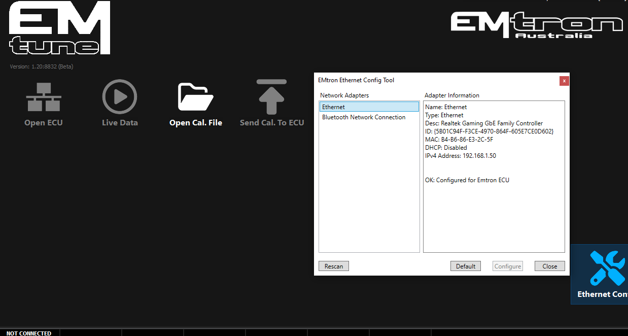
Emtune 1.20.0 and onwards includes a wizard to help configure the ethernet connection (Bottom right of the splash screen)
The wizard may fail to configure the adapter if a previously used adapter was set to the same IP address. Windows can be very finicky about this.
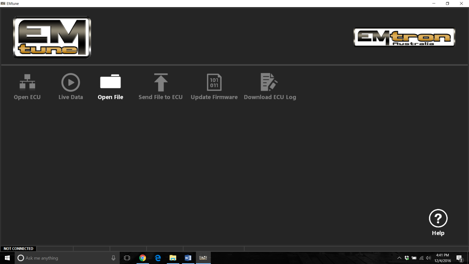
This will be visible when an ECU is no connected / detected.
When the ECU is connected & the IP address correctly configure, the software will acknowledge this in the bottom left corner.
The process to manually configure windows 11+ is as follows:
Manual IP Config
Info on configuring the IP address for different windows version can be found here:
When a correctly configured Ethernet port is in use together with a known good communication cable and you remain unable to establish a connection.
Power supply to the ECU must be verified. That is, the next step is to determine if the ECU is powering up.
Without voltage to the ECU supply pin.
The ECU will fail to power up thereby making communication impossible.
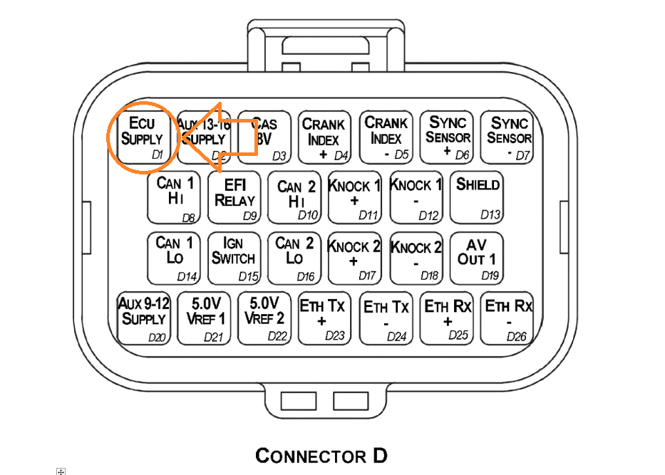
For the KV Series ECU’s this is pin D1
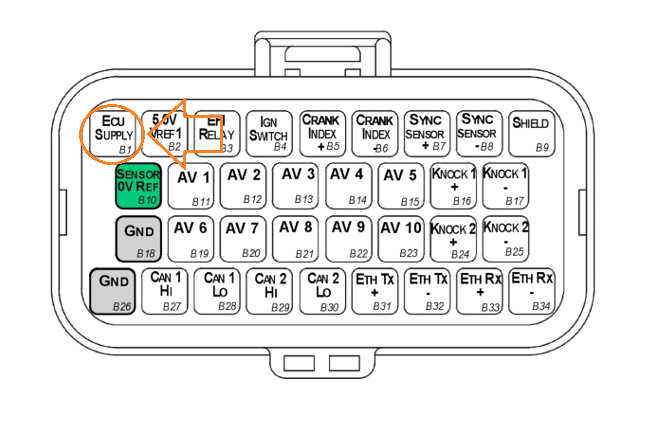
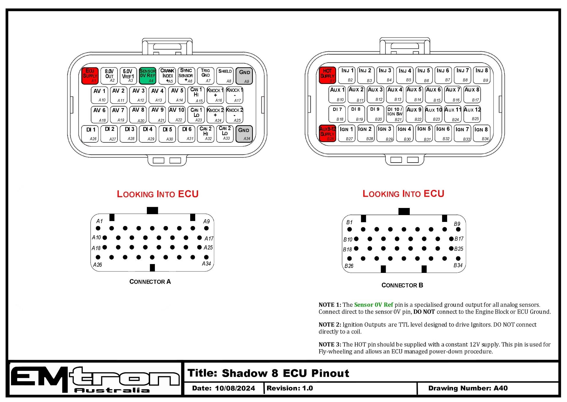
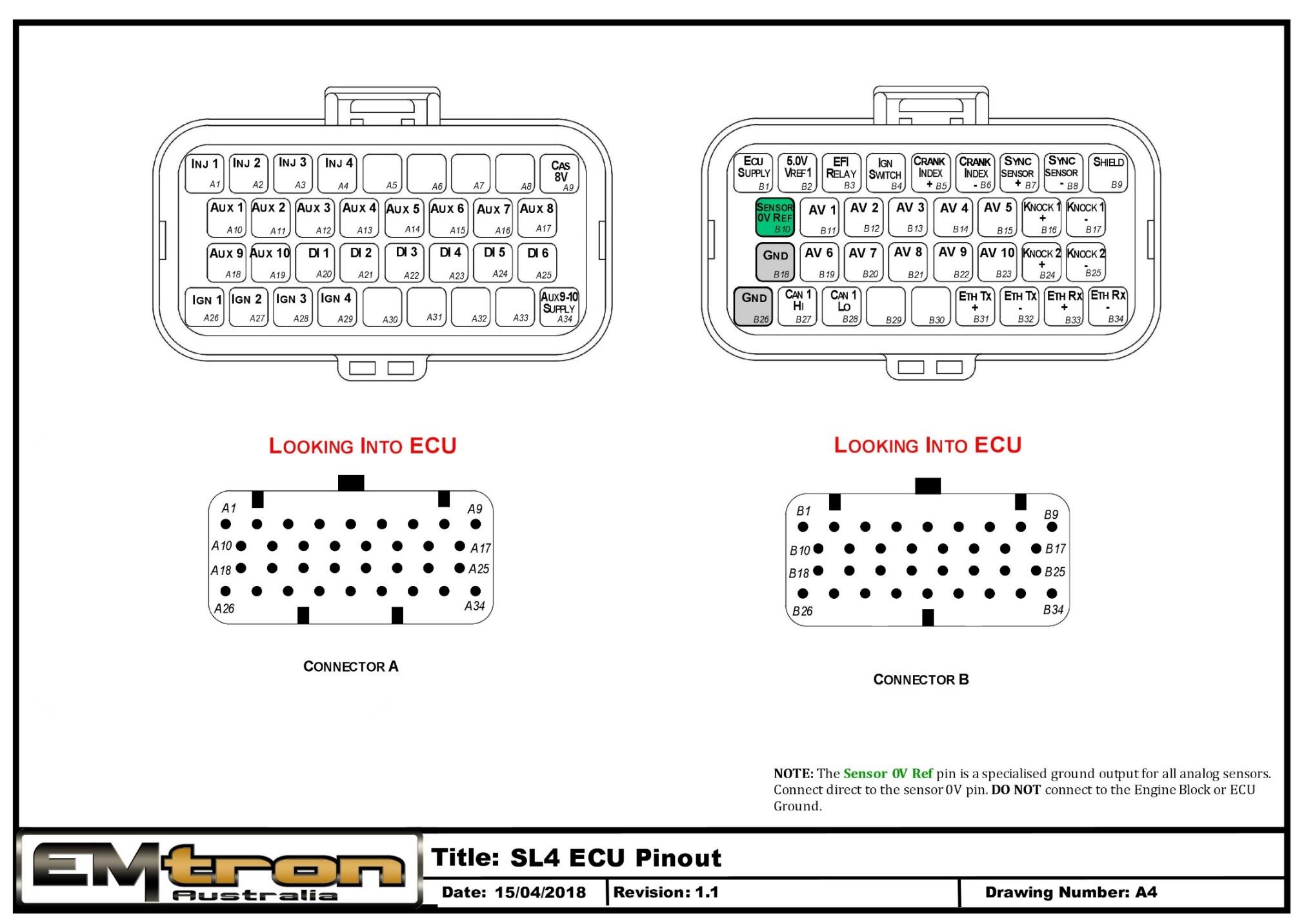
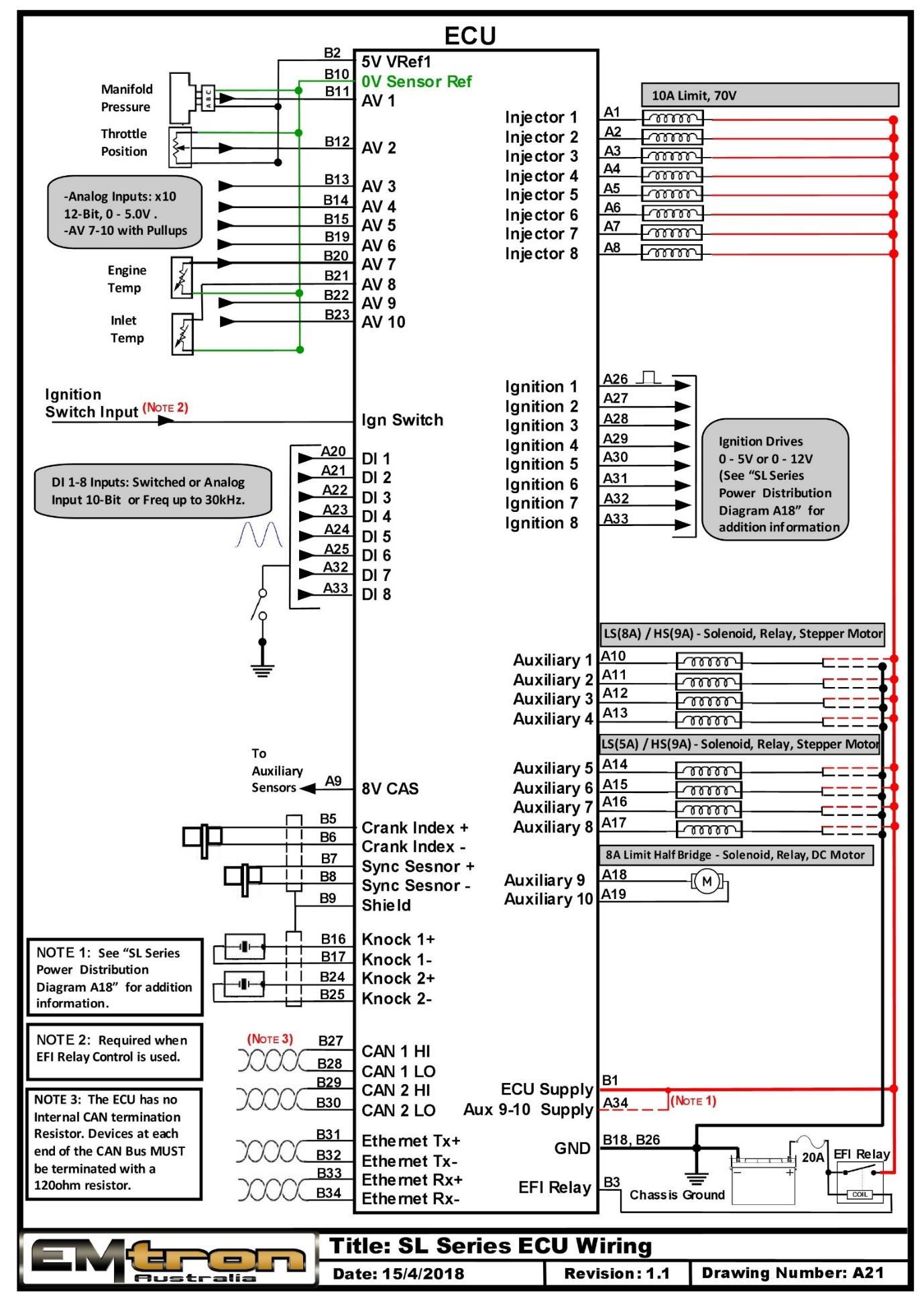
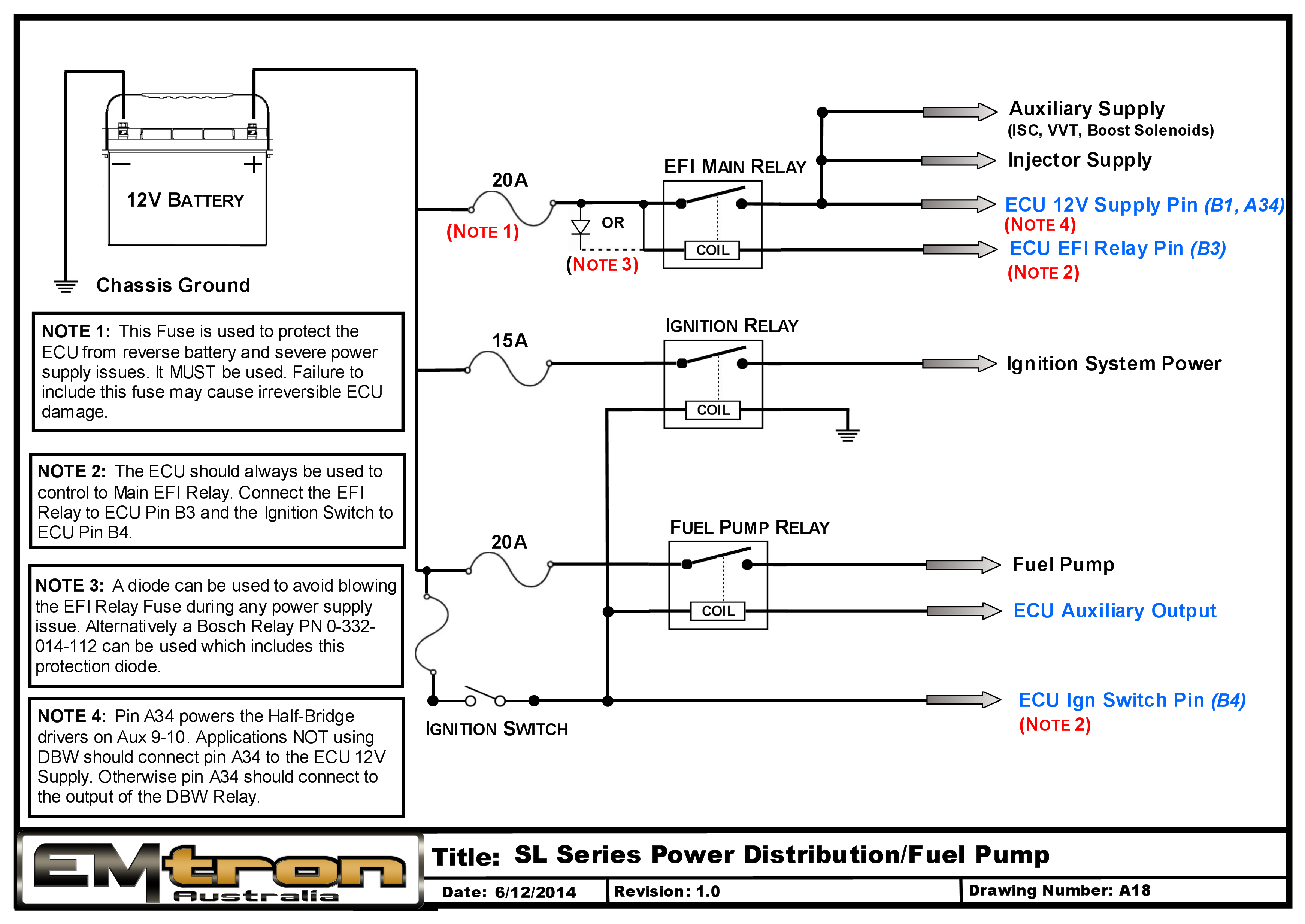
For the SL series ECU’s, this is pin B1
If 12V is not present at D1/B1 with ignition ON, you will need to determine the power supply fault.
Subsections of Ethernet
Windows 11
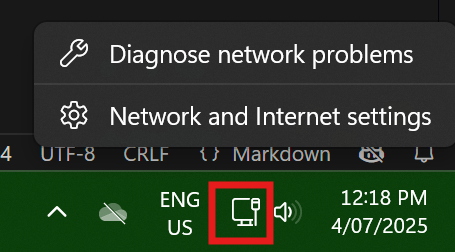
Right click on the Network Connection icon in the system tray. It may appear as a wired connection or a wifi icon.
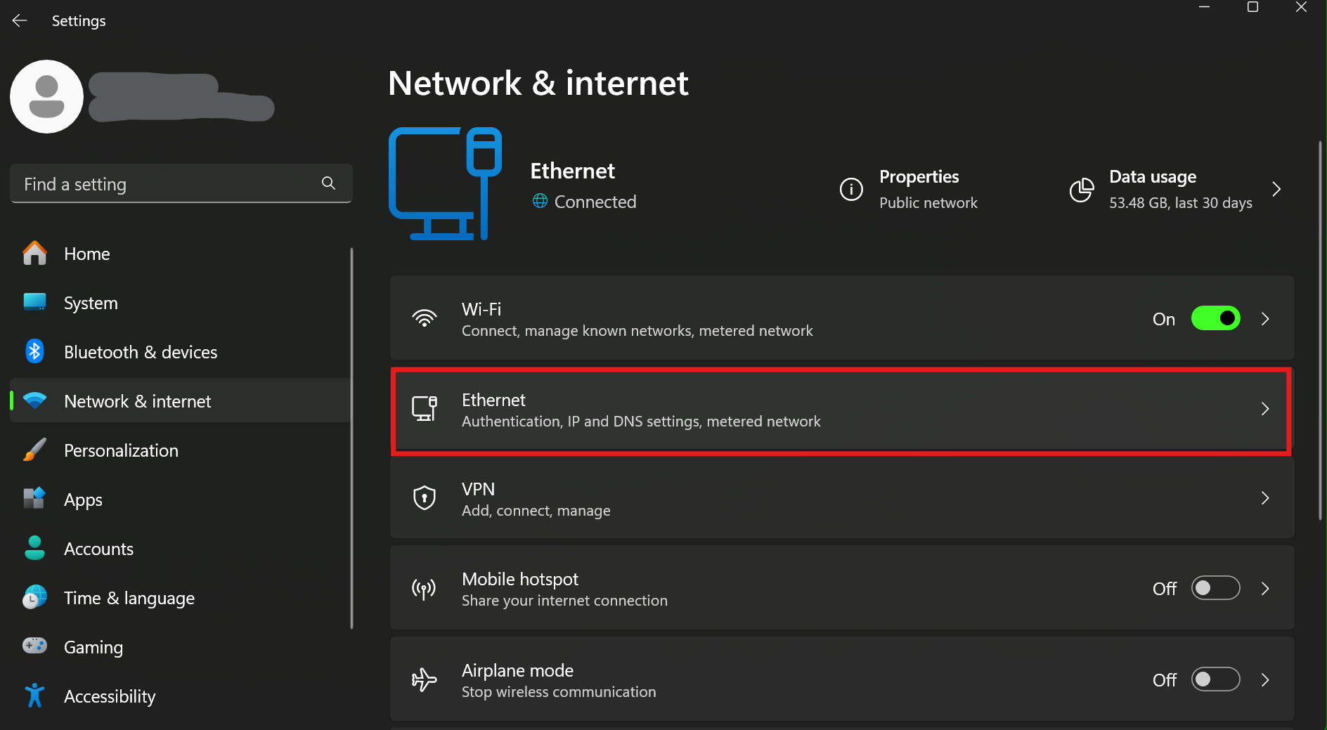
Click on Ethernet
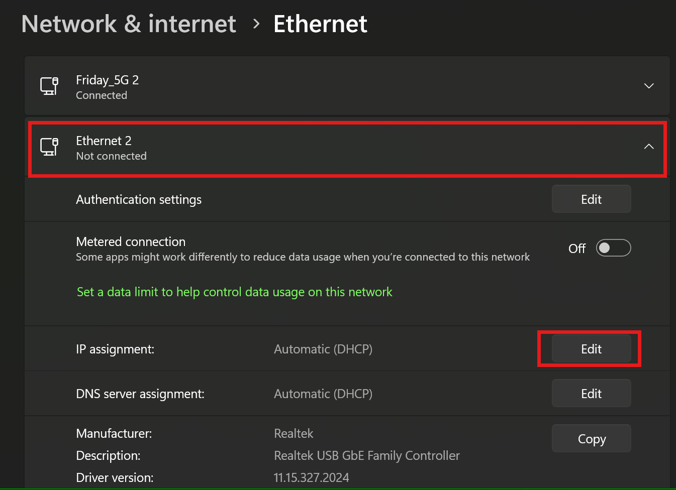
Expand the settings for your ethernet adapter and click on the Edit button for IP Assignment.
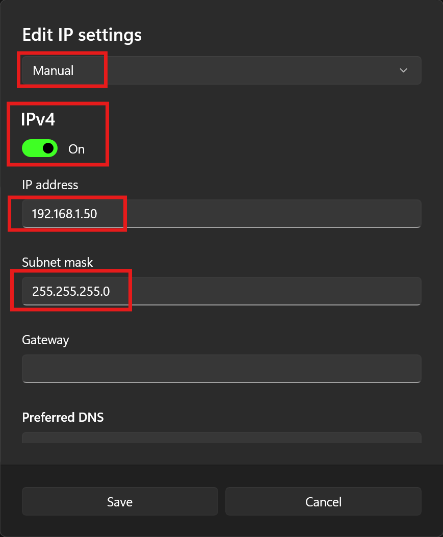
Set it to Manual, turn on IPv4, and enter the emtron IP Address and Subnet mask.
Click Save.
Done. Connect the Emtron Ethernet cable.
Windows 10
To setup the Ethernet on Windows 10 ready for the ECU connection use the following steps.
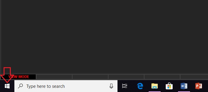
Left Click Windows Icon - Bottom Left corner
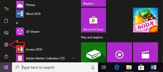
Left Click Settings Icon - 2nd from bottom on Left
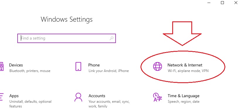
Left Click “Network & Internet” - Top Right
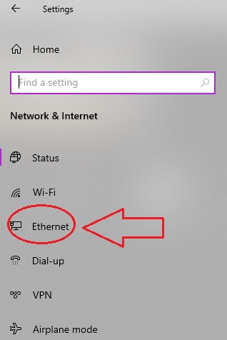
Left Click “Ethernet” - 4th from Top on the Left
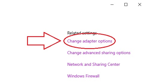
Left Click “Change Adapter Options” - Top Right
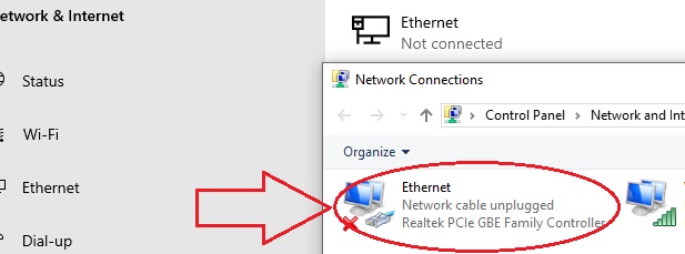
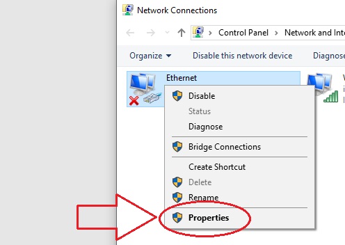
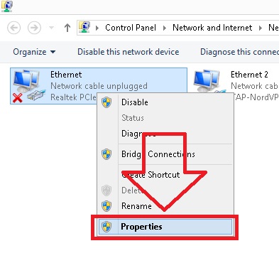
Right Click “Ethernet”
Left Click “Properties”
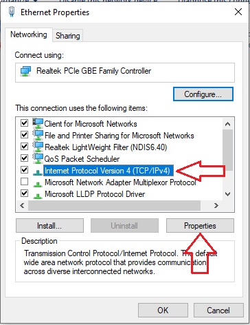
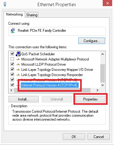
Select “Internet Protocol Version 4 (TCP/IPv4) and Left Click “Properties”
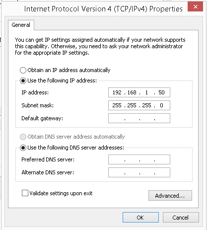
Use the following IP address
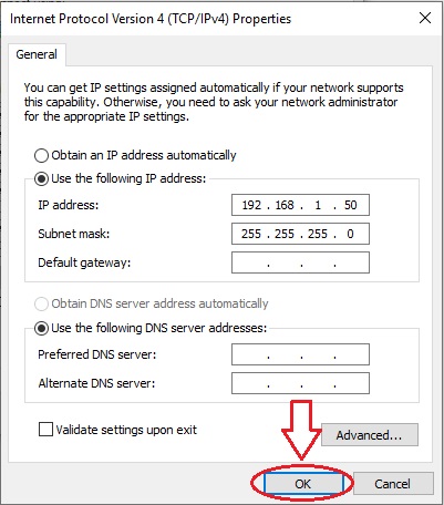
Left Click “OK” and exit, the process is complete
Done. Connect the Emtron Ethernet cable.
Windows 8.1
To setup the Ethernet on Windows 8.1 ready for the ECU connection use the following steps.
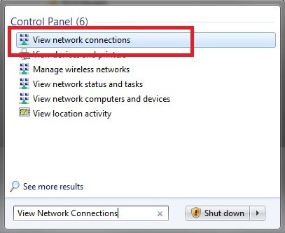
Type “View Network Connections” into the search window, accessed from the start menu. Windows should provide a list of results. Select View Network Connections.
Or alternatively if the search function doesn’t provide this:
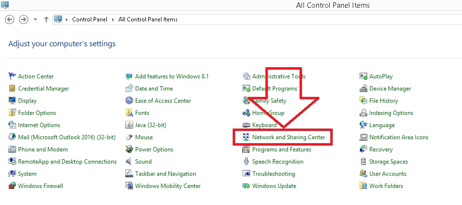
Start > Control Panel > Network and Sharing Center.
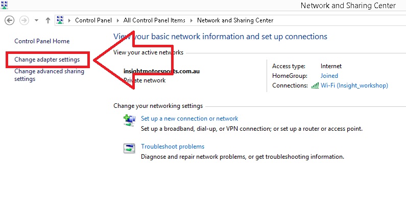
Once in this menu select “Change Adapter Settings”
Once in this menu select “Change Adapter Settings”
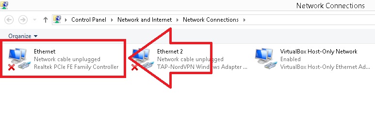
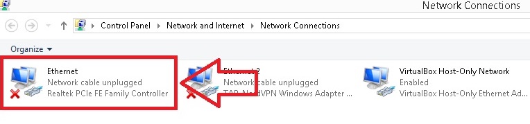
The below menu should be visible. Select “Ethernet”
Right click to Access Properties
Select TCP/IPv4 then click Properties
Select “Use the following IP address” and enter in the address 192.168.1.50. The Subnet should automatically default to 255.255.255.0. Click OK.
Done. Connect the Emtron Ethernet cable.
Windows 7
To setup the Ethernet on Windows 7 ready for the ECU connection use the following steps.
Type “View Network Connections” into the search window, accessed from the start menu. Windows should provide a list of results. Select View Network Connections.
or alternatively if the search function doesn’t provide this:
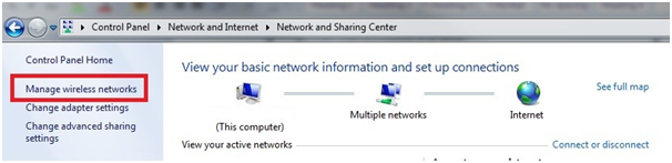
Start > Control Panel > Network and Internet > Network and Sharing Center.
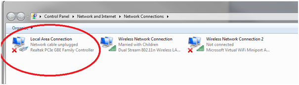
Once in this menu select “Change Adapter Settings”
The below menu should be visible. Select “Local Area Connection”
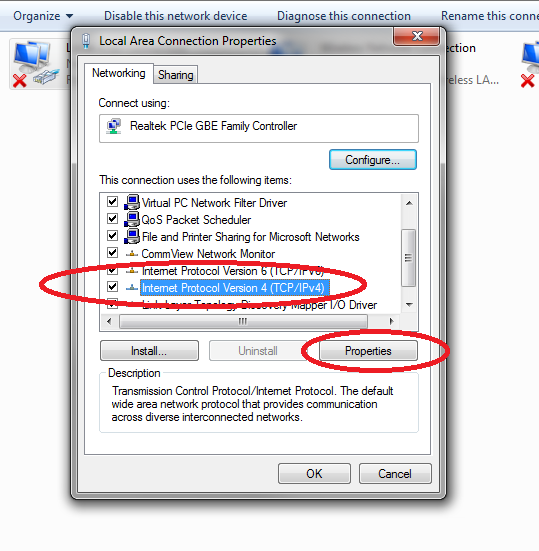
Select TCP/IPv4 then click Properties
Select “Use the following IP address” and enter in the address 192.168.1.50. The Subnet should automatically default to 255.255.255.0. Click OK.
Done. Connect the Emtron Ethernet cable.
Windows XP
Emtune is no longer developed to offer Windows XP compatibility.
Basic Configuration Guide
Software Navigation
From the Welcome Screen, selecting Open File, or Open ECU (ECU Detected is required) the calibration file will be opened.
From here, you can navigate through a number of menus, tabs, sub tabs, etc.
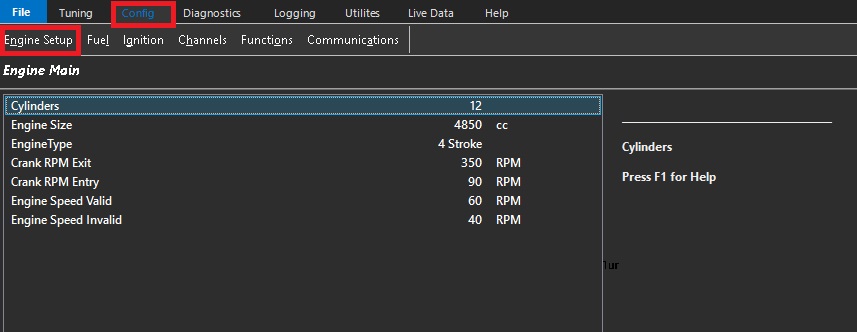
For configuration, clicking the config tab at the top is where to start.
The Emtune software has a very systematical approach to configuration.
Start on the left side “Engine Setup”, and work your way over from left to right.
Do not skip sections. Following this practice as accurately as possible will ensure tuning process will move smoothly in the future.
Improper entry in any part of the setup could be detrimental to the electronics AND the hardware!
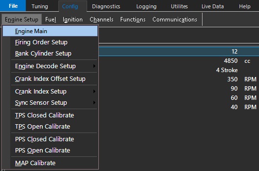
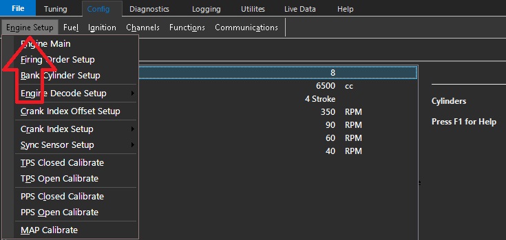
Engine Setup
Setup each tab from top to bottom. See help file for explanation of each individual function, as well as help text in the respective configuration screens.
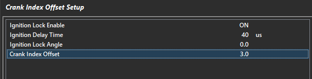
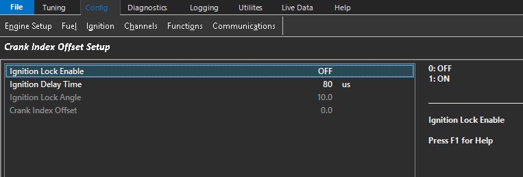
Crank Index Offset Setup
This section synchronizes the engine timing.
**Crank index offset MUST always be checked regardless of trigger pre-configuration.
1)Always check crank index position at ignition lock angle 0.0 (especially when running waste spark).
2) Ignition delay time should be validated at this time and adjusted.
3) As RPM is increased, timing should stay at the ignition lock angle.
If this does not occur - Adjust the ignition delay time until this is achieved.
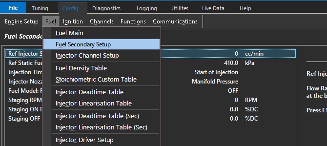
Define all your fuel setting under the Fuel heading.
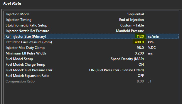
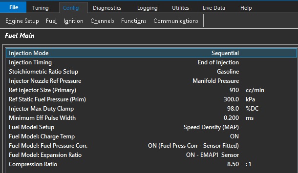
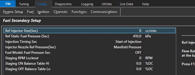
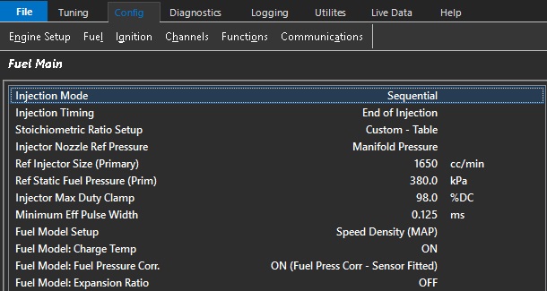
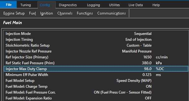
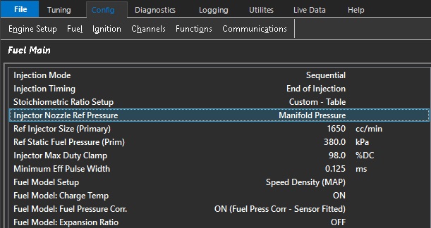
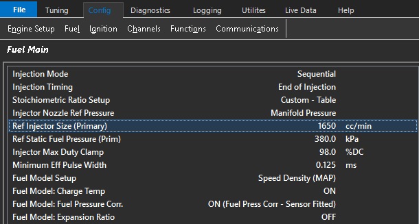
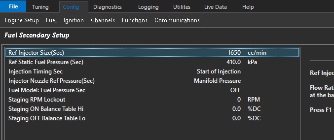
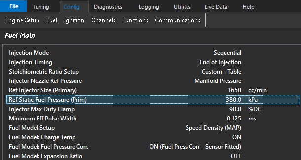
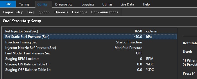
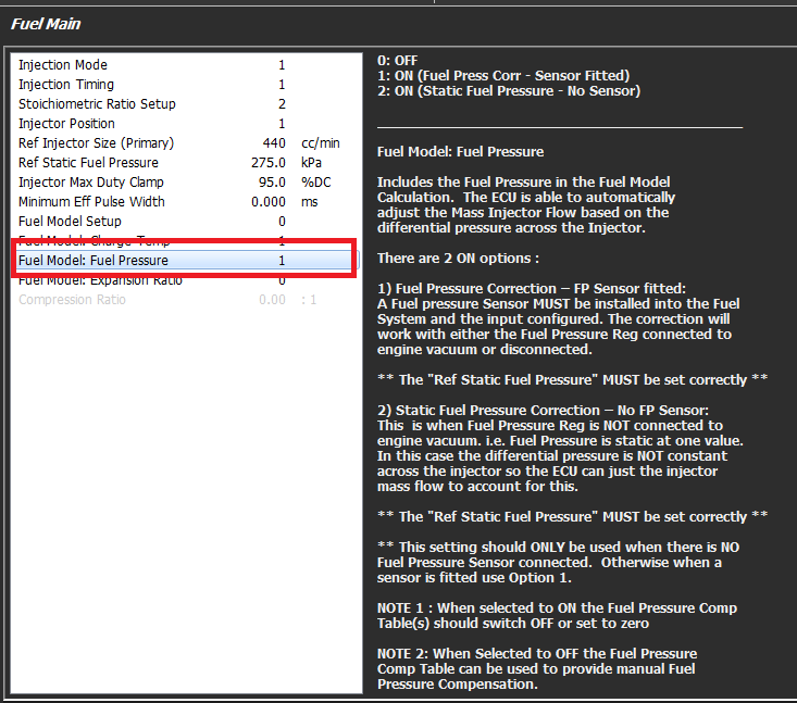
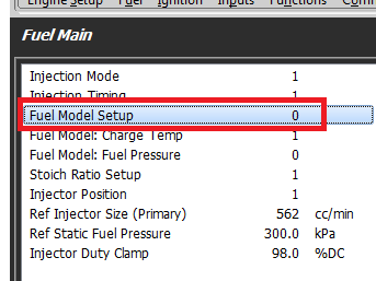
Fuel Flow Rate/Ref Injector Size
The Ref Injector Size flow rate must match the Ref Static Fuel Pressure value
The Ref Static Pressure Value is pressure value that differential/relative fuel pressure at the injector for this injector flow rate value.
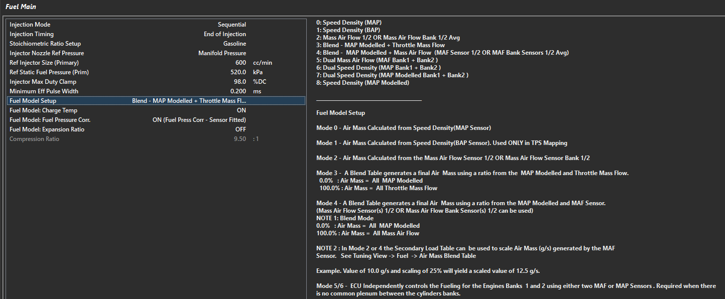
** If Fuel Model: Fuel Pressure Corr. Is “On (Fuel Press Corr – Sensor Fitted)”, then this Ref Static Fuel Pressure value is used as the base Fuel Pressure Differential.
The following runtimes will be generated from this information:
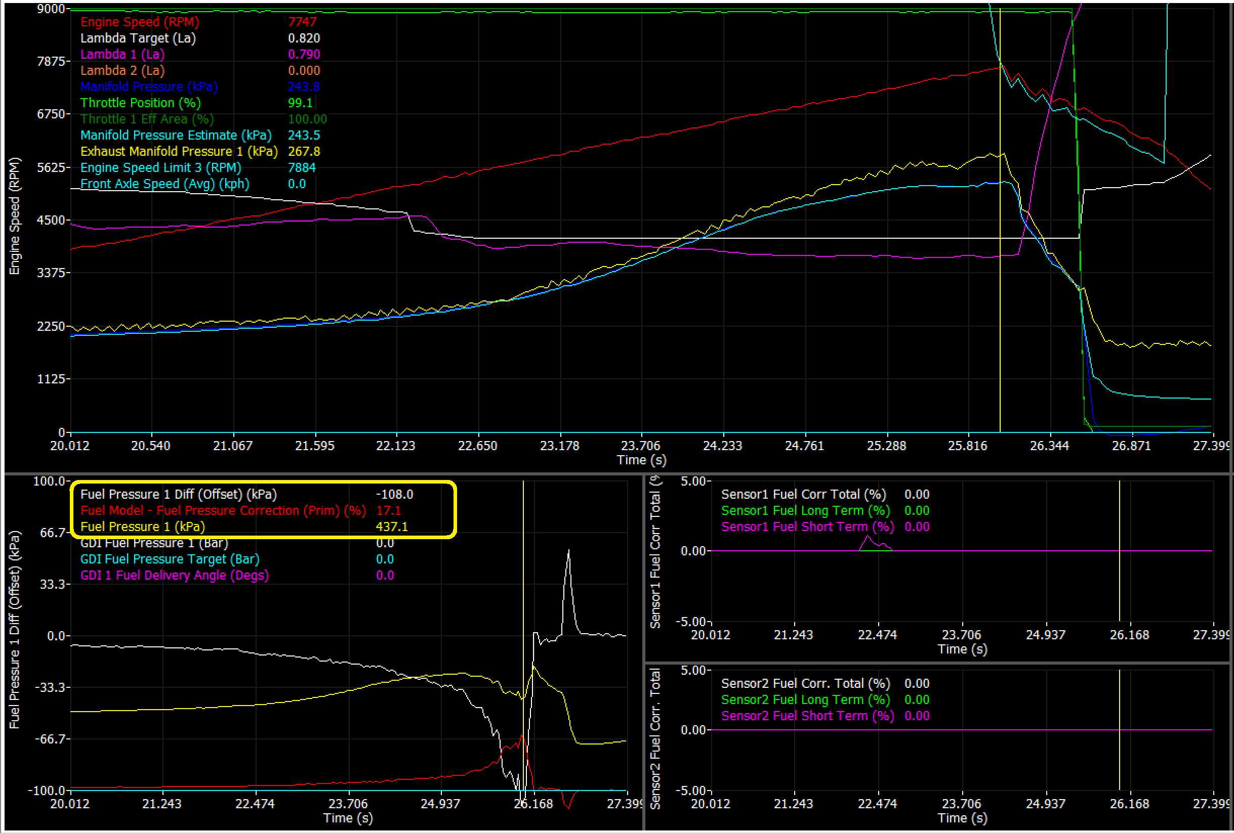
Fuel Pressure Diff – This is the effective pressure at the injector
Fuel Pressure Diff Offset – This is the deviation from the differential pressure target (or the reference static pressure entered commonly
Fuel Model Pressure Correction – The percentage of compensation added/subtracted based on differential pressure offset
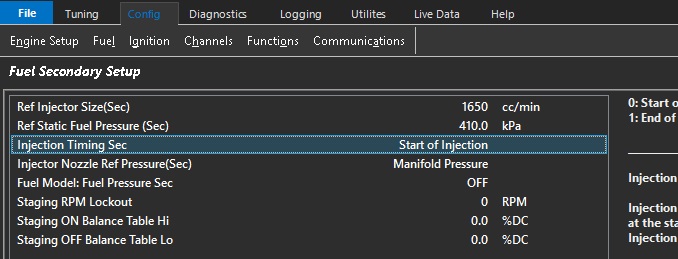
** If Secondary Injection is used, Fuel Pressure 2 channel MUST be used, and all runtimes above (2) are available and act independently.
These channels can be used all over the ECU calibration, for compensation for deadtime, engine protection, etc.
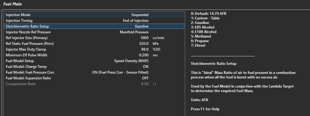
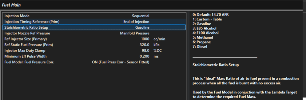
Stoichiometric Ratio Setup
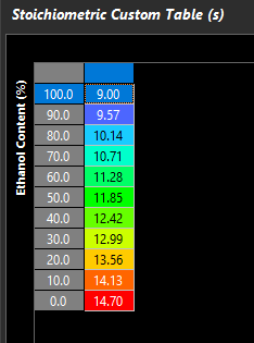
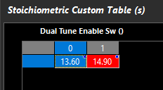
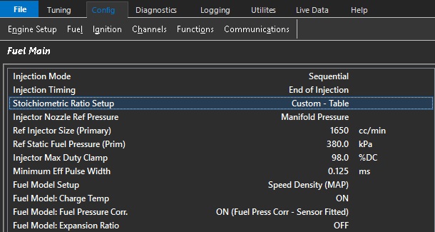
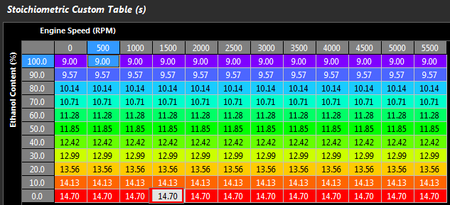
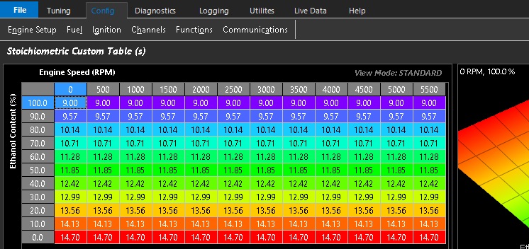
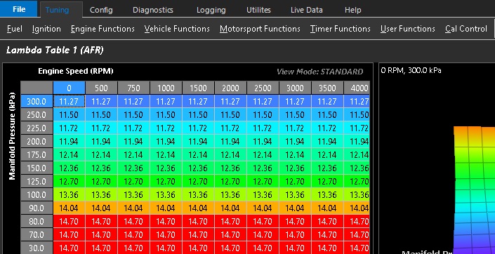
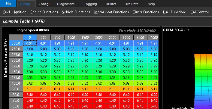
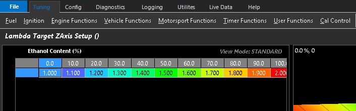
The airflow model will determine air mass flowing through engine a number of ways, then reference the stoich setup to determine how the “Lambda Target” table quantifies the fuel mass needed in the model. There are a number of pre-defined fuel types to choose from, but also a “Custom - Table” selection for pump fuel with ethanol, flex fuel vehicles, etc. See the ECU sample file (Custom - Table), or build your own table if using a odd fuel.
**** Not having the correct Stoich Ratio will bake large error into the entire model and compensations**
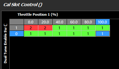
Above is showing how two fuel types can be used with different Stoich values with a “Dual Tune Enable Sw”
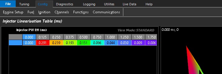
Injector Deadtime and Linearsation
It is very important to have your Injector Size (cc/min) as accurate as possible, as well as the Ref Static Fuel Pressure.
If using any fuel pressure compensation in the model (which you can turn on and off), the Ref Static Pressure is what is used to compensate injection quantity vs effective fuel pressure (differential fuel pressure).
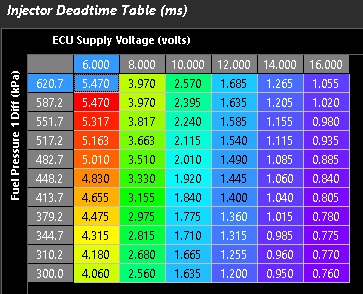
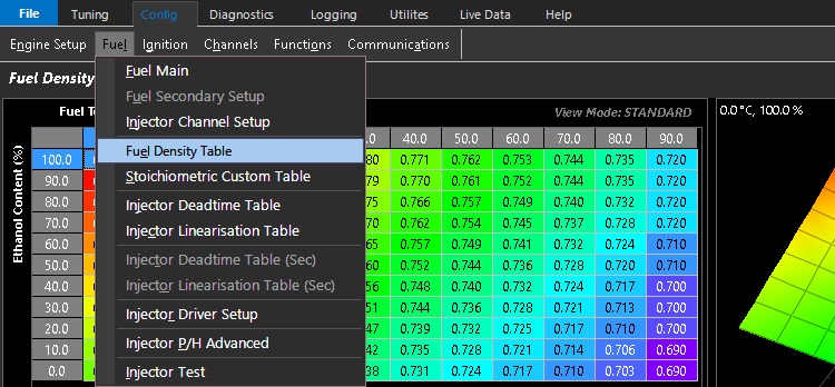
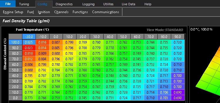
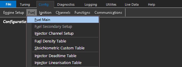
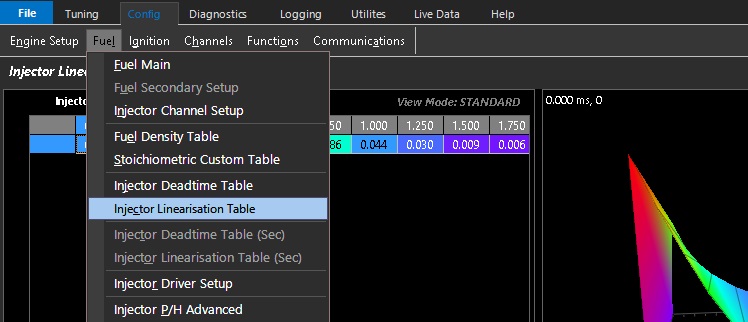
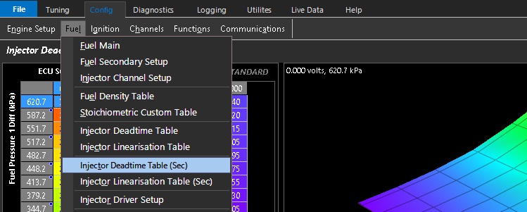
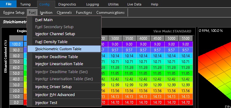
There are 3D table functions for Fuel Density, Custom Stoichiometric (commonly used for flex fuel function), Deadtime, and Linearizion.
**** Injector deadtime accuracy is critical.****
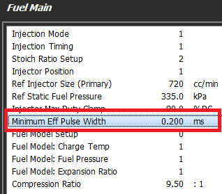
Correct deadtimes ensure the proper amount of pulse width is added to the effective pulse width (as calculated by the fuel model).
Improper time entry usually results in exaggerating VE entries, especially in engine load ranges when the pulse width is small.
It should be taken into consideration that effective fuel pressure affects injector deadtime, so using injectors with good data sheets is the best idea. Most good injectors have a latency multiplier vs fuel pressure, or a complete table available.
These values should be translated and entered into the tables as accurately as possible.
Tuning Tip:
Injector Dead times can be validated using the Emtune Software by using the Wideband Lambda control. If you add 10% to your VE table (@ 3000rpm / 80kpa load for example), you should see a corresponding negative 10% trim applied via the Wideband lambda control. If you don’t, then you know your dead times need some attention.
By utilizing a dead time table available in your Emtune software that is close. The correct dead time for your injector can be quickly arrived at by simply globally moving the table up & down. The voltage slop of the dead times can be further validated by removing the alternator charge and allowing the supply voltage to drop away. Correct dead times allow the engine to operate correctly over a wide range of variable conditions
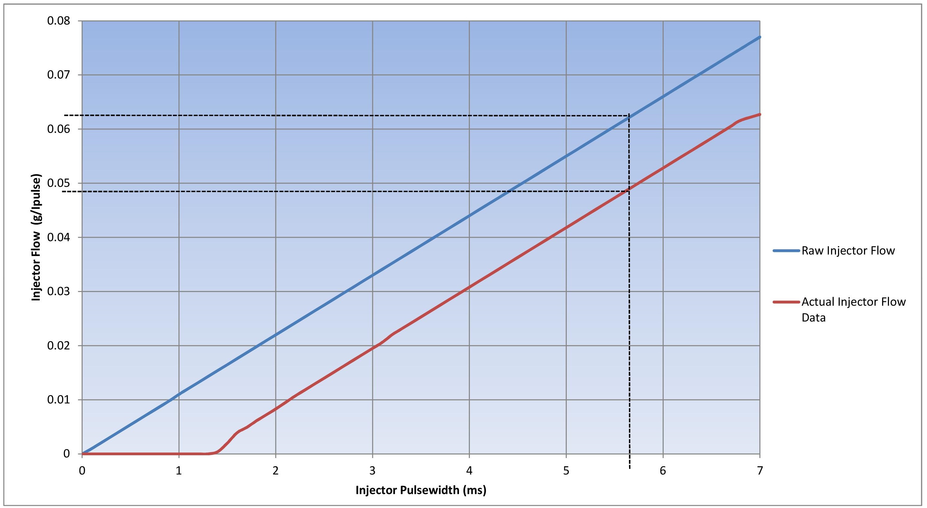
** Injector Linearization is considered a raw pulse width correction factor to correct the fuel flow at different pulse widths
(generally more sensitive at low pulse widths). These numbers can be positive or negative.
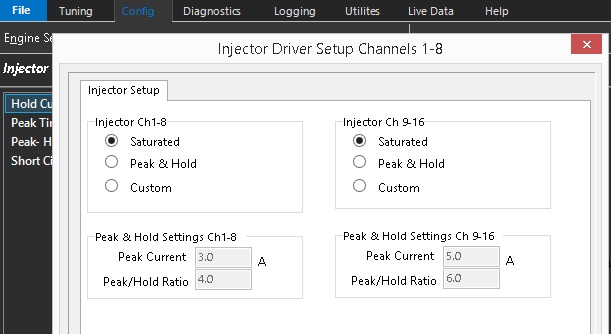
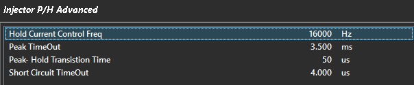
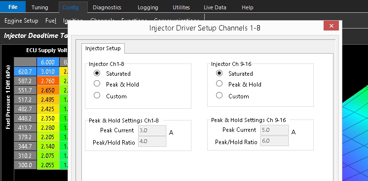
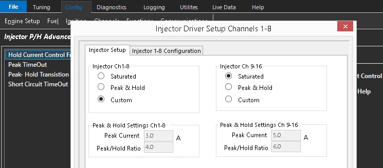
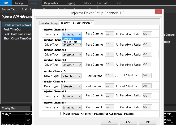
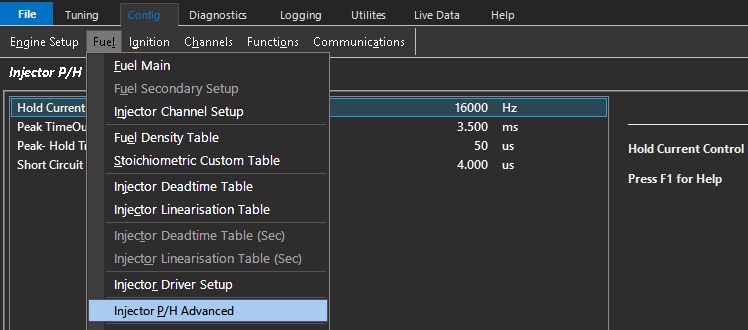
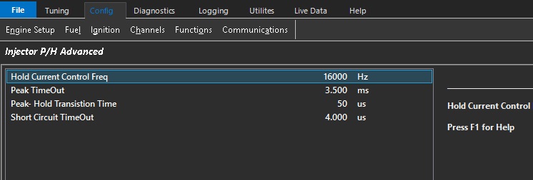
There is a full configuration function for peak and hold injection where you can define the injector type (saturated vs peak and hold), and define opening and hold currents.
The injector test function also allows you to pulse each injector anytime the engine is off.
Ignition
Define all your ignition setting under the Ignition heading.
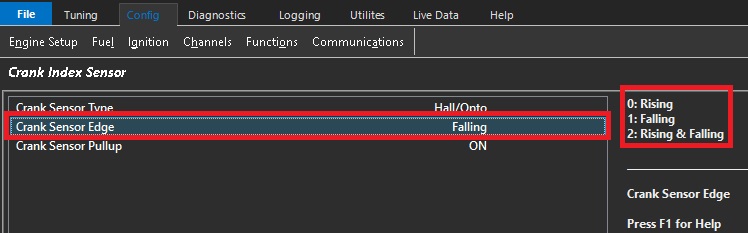
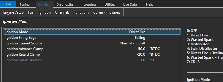
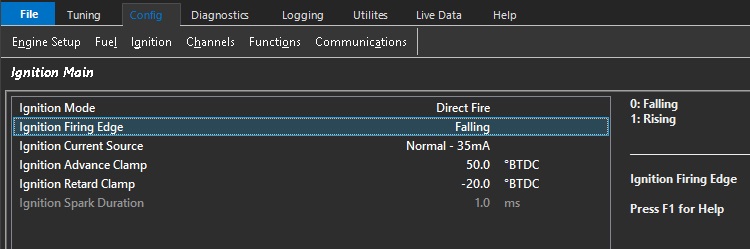
**Ignition firing edge synchronizes the calculated ignition timing with the physically ignition system itself.
In most cases where the ignition system has ECU controlled dwell (following the dwell table entry), the firing edge will be falling as this is when the coil will inductively transfer spark energy to the spark plug.
Mapped dwell time affects coil charge before this event.
Ignition systems that require the opposite signal (dwell period reversed) generally have a rising firing edge.
Ignition systems that control their own dwell period separately also generally require rising firing edge.
Ignition Timing should be validated with a timing light ALWAYS.
A good test for correct firing edge configuration is to change the dwell time and observe the ignition timing does not change.
Improper set up here can cause false ignition timing, weak spark and even DAMAGE to the ECU or the vehicle Ignition system.
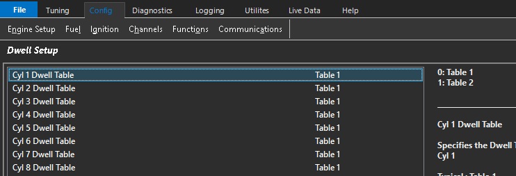
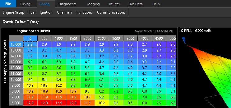
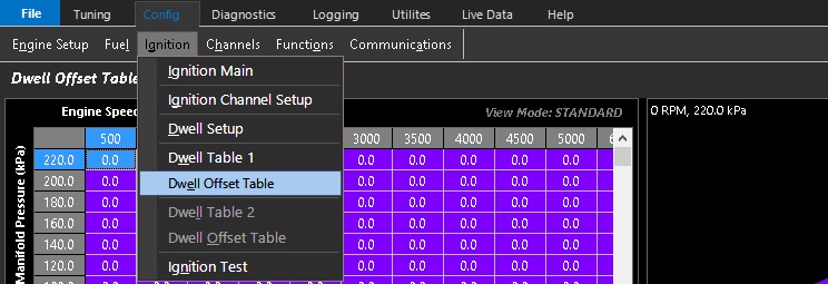
Each cylinder can be assigned two different dwell tables. Each dwell table can be offset by a secondary table as well.
The ignition test function also allows you to pulse each injector anytime the engine is off.
Inputs
This comprehensive setup will specify all Inputs to the Emtron ECU system.
It has a tab structure which has a similar function to the configuration setup.
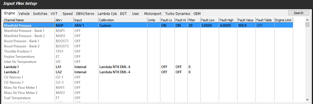
Input Pins
Inputs can be configured using select analog and digital inputs.
The hardware configuration for different ECU types is listed below.
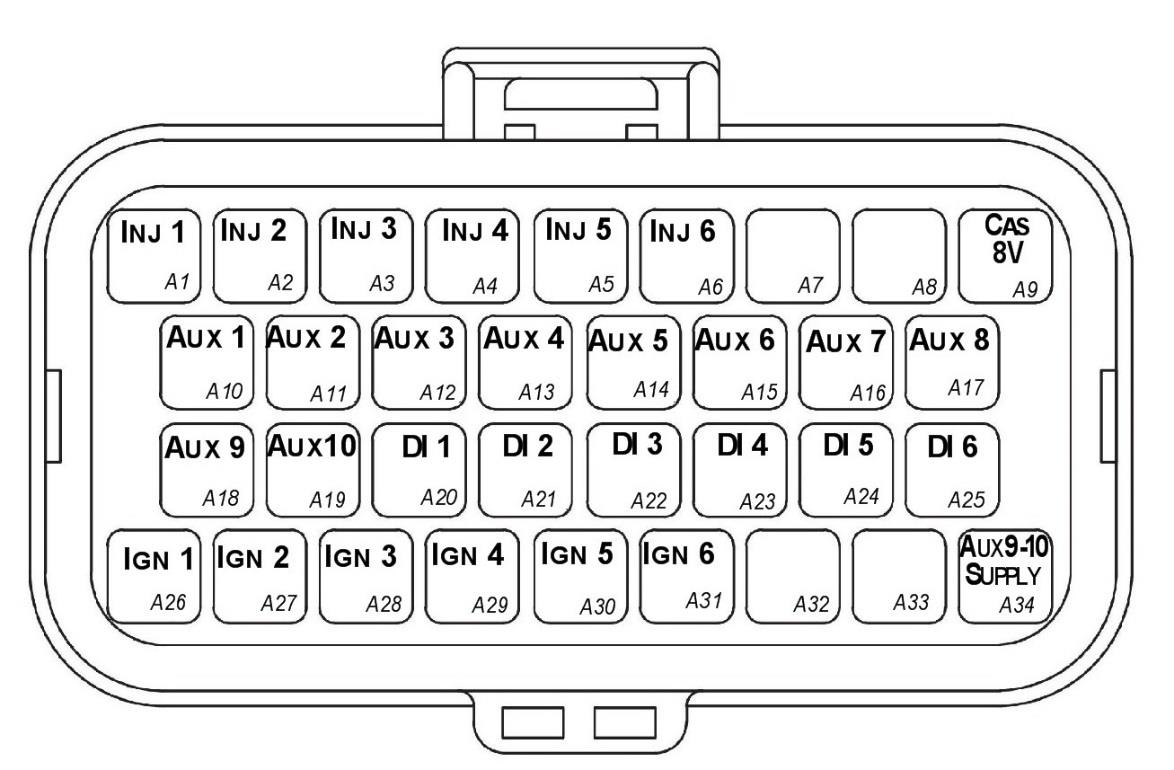
SL Series ECU –
ANV 1-10 12 bit resolution 0-5v analog voltage inputs
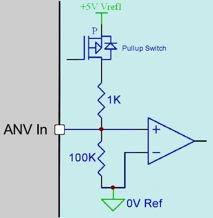
ANV 7-10 have switchable pull up to 5v through 1k ohm (temperature)
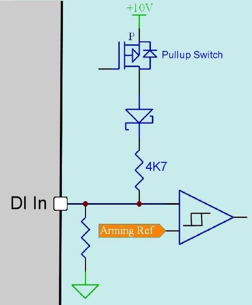
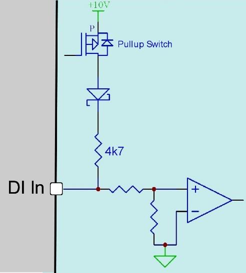
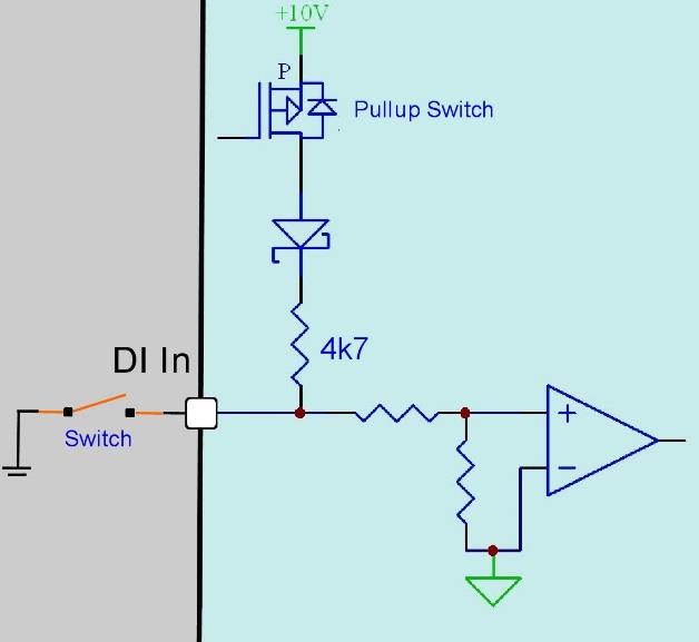
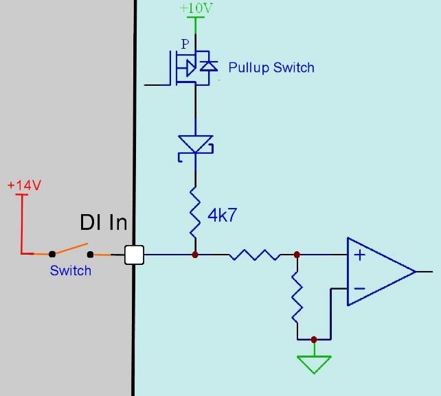
DI 1-8 0-30khz input frequency range with switchable pull up to 9v through 4.7k ohms
DI 1-8 10 bit resolution 0-20v analog voltage input mode
**KV Series ECU –**
ANV 1-16 12 bit resolution 0-5v analog voltage inputs
ANV 7-12 have switchable pull up to 5v through 1k ohm (temperature)
DI 1-8 0-30khz input frequency range with switchable pull up to 9v through 4.7k ohms
DI 9-14 Standard switch input (low frequency) switchable pull up to 9v
DI 1-8 10 bit resolution 0-20v analog voltage input mode
DI 9-14 Low resolution 0-20v analog voltage input mode
Starting on the left to right and moving through all required and optional inputs and setup.
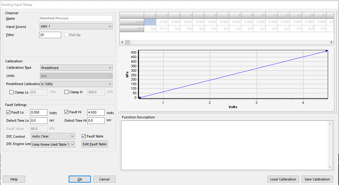
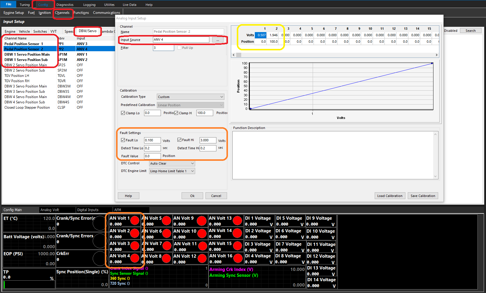
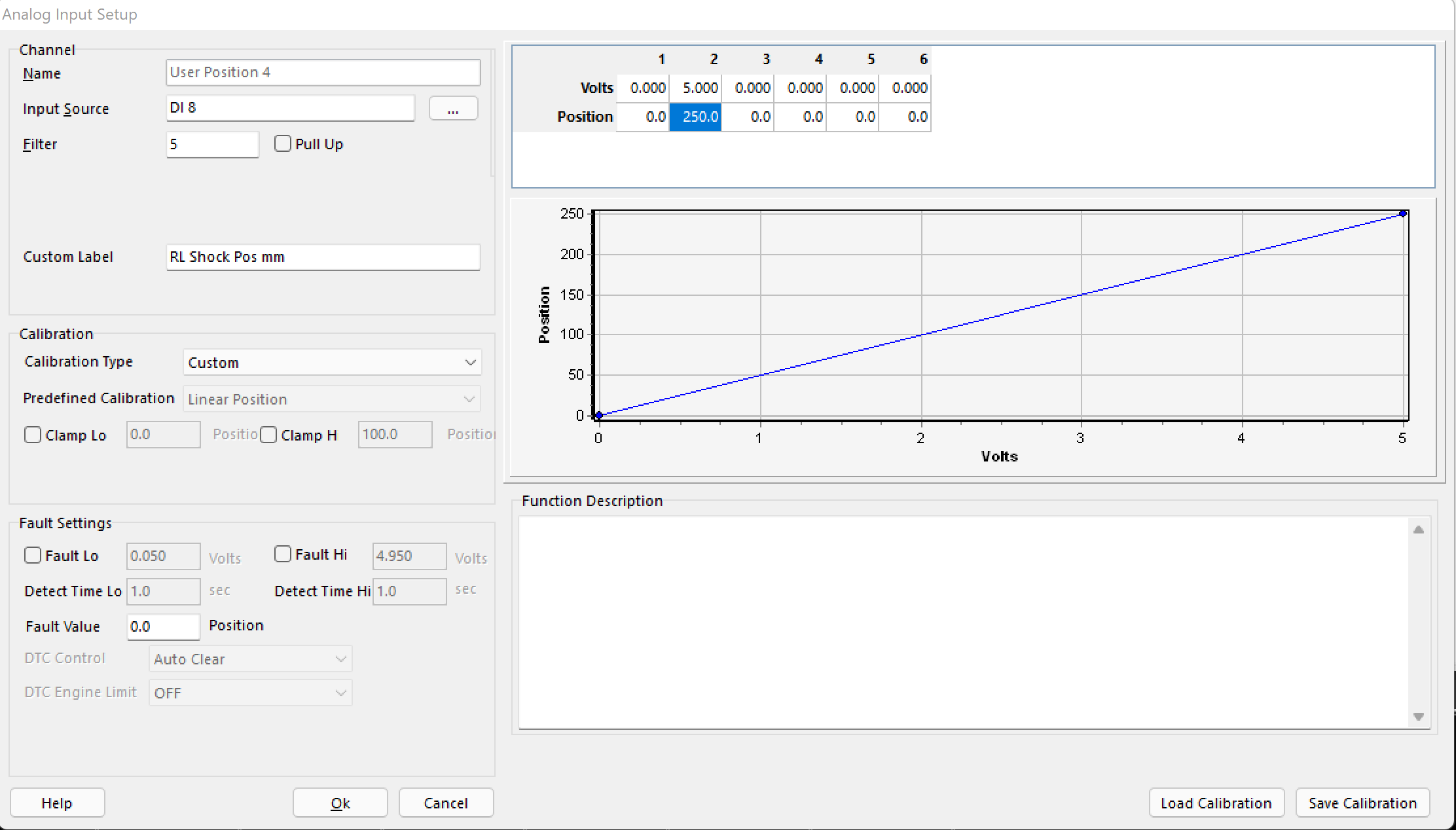
Analog voltage config window:
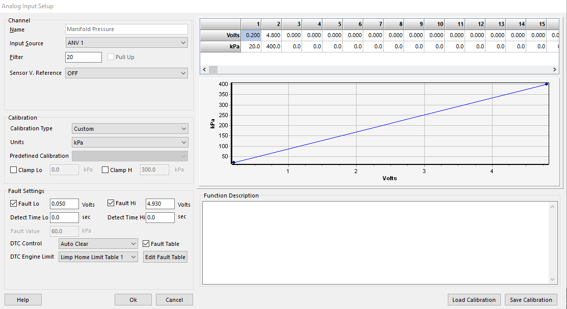
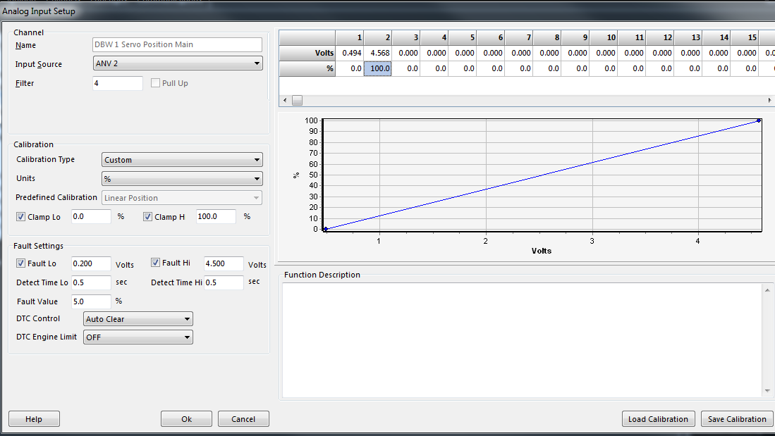
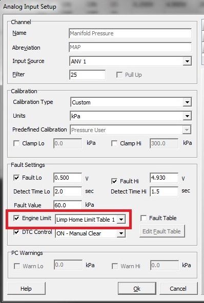
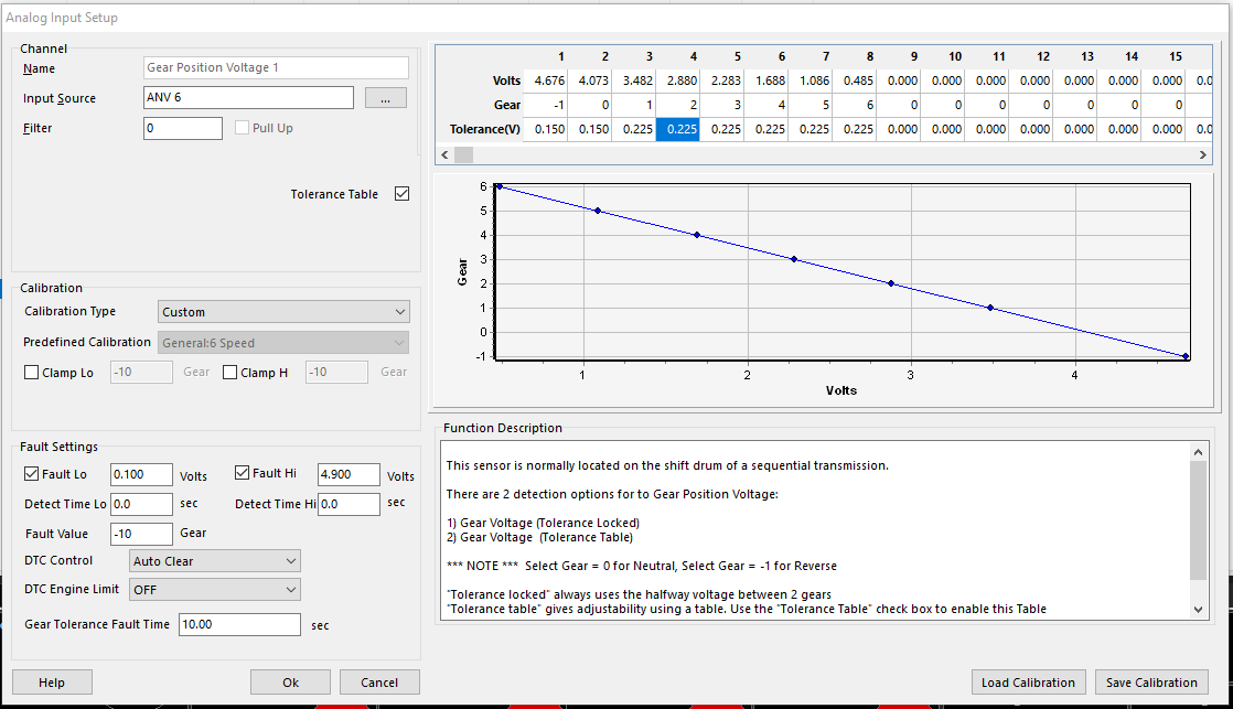
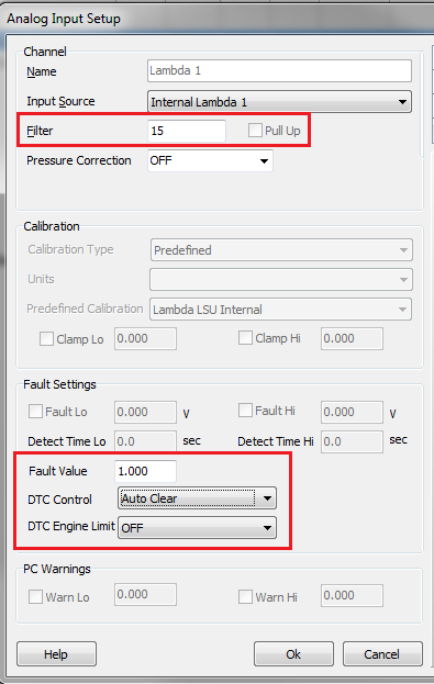
Sensor input source, filter, calibration, clamp, fault settings, fault value (substitute value), DTC control, and DTC engine limit control are all configured here. There are a number of popular “pre-configured” sensor styles.
If using thermistors, “pull up” must be switched on (only available on ANV 7-10/12).
**Digital inputs can all be pulled up, but they cannot be used for thermistors as the pull up voltage is 9.0V
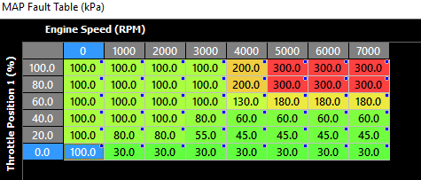
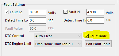
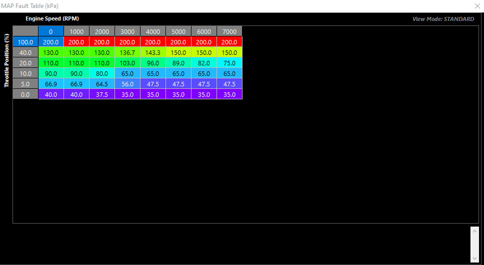
**Major sensors have the ability to enable “fault table” which allows the user to create an active look up table for substitute values.
Example below is for MAP sensor failure, using TP and engine speed to populate active substitute.
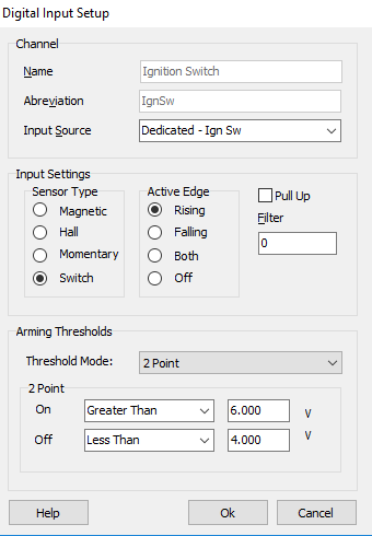
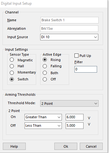
A simple switch configuration for digital input (ignition switch dedicated input):
Input can be configured as a regular toggle switch, magnetic, hall, or momentary switch.
Edge configuration should be appropriately selected based on switch configuration.
Pull up can be used for ground switch inputs (2 point config would be opposite, falling edge trigger).
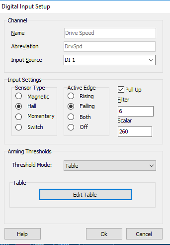
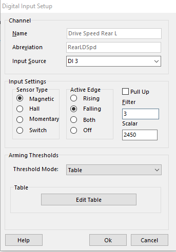
For high speed inputs, configuration is similar:
High speed inputs (DI 1-8 only) should have “table” as threshold mode, as this will specify the cross over voltage point.
This is similar to “arming thresholds” when configuring triggers
“Scaler” will facilitate the input frequency to unit conversion.
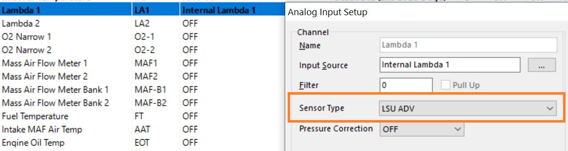
If using KV series internal Lambda sensors, select “Internal” under Input Source
If using CAN bus OEM inputs, select “CANBUS OEM” under Input Source
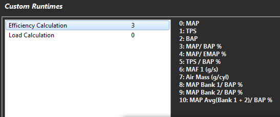
Custom Runtimes
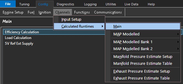
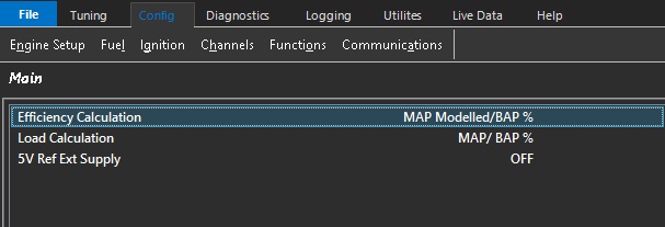
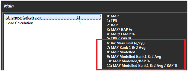
Efficiency calculation is a runtime commonly used as a load point for fuel tables.
You can select from a number of Emtron calculated runtimes.
Load calculation is a runtime commonly used as a load point for ignition tables and lambda target tables.
You can select from a number of Emtron calculated runtimes.
DI Arming Thresholds
These are the tables generated by high frequency inputs when using the “table” threshold mode.
Lambda Pressure Correction
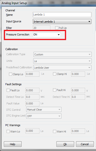
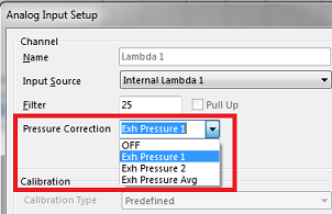
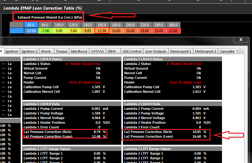
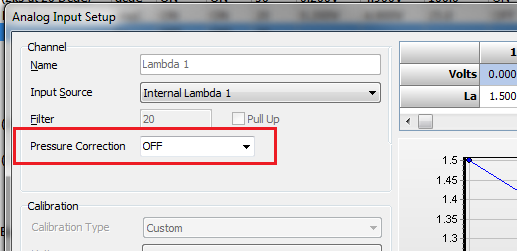
If using Lambda sensors in situations where exhaust back pressure becomes a factor (Lambda sensor installed before turbocharger or other exhaust restriction), using an exhaust manifold back pressure sensor input allows for correction of the lambda measurement.
Functions
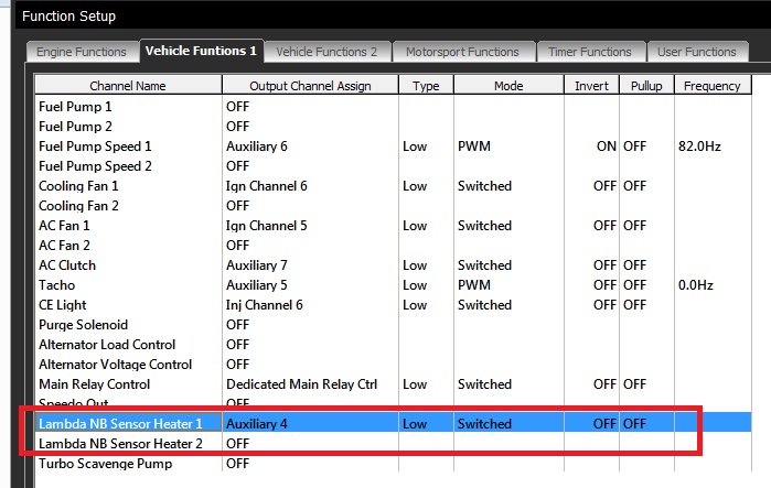
Like Input Pins, this is a comprehensive setup that will specify all outputs to the Emtron ECU system. It has a tab structure which has a similar function to the configuration setup.
Each function that is being used can be enabled here. If there is a required output, then an appropriate output channels can be selected.
An overview of output channel functions from Emtron (see help for more details):
SL Series ECU –
AUX 1-4 Low side
AUX 5-8 Low/High side
AUX 9-10 H-Bridge (One DBW)
Spare fuel and ignition channels can be driven low side
**KV Series ECU –**
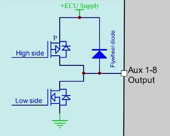
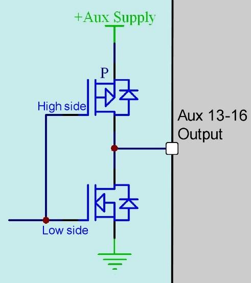
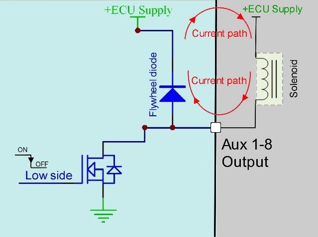
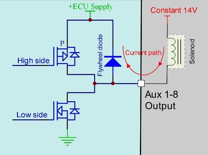
AUX 1-8 Low side/high side
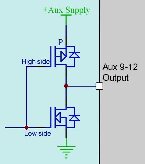
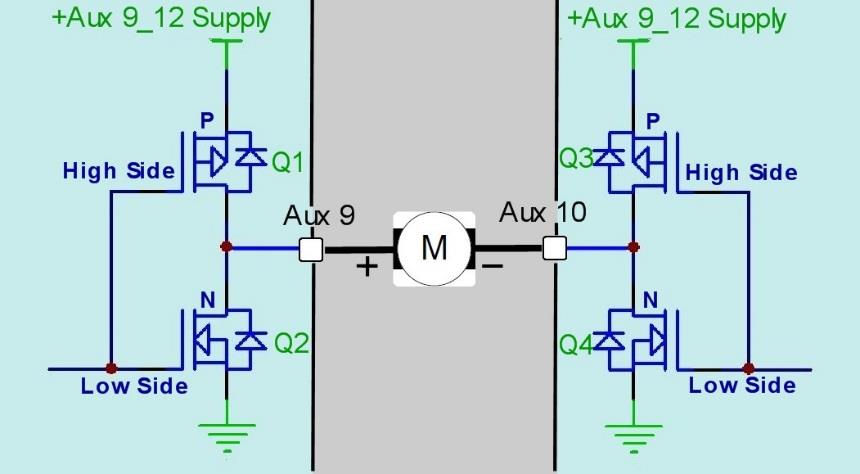
AUX 9-12 H-Bridge (Two DBW)
AUX 13-16 Low side/high side
AUX 13-16 H-Bridge (KV12+ - Two DBW)
Spare fuel and ignition channels can be driven low side
**High side drivers and H-Bridge often need control of supply voltage to specified pin locations – see help document
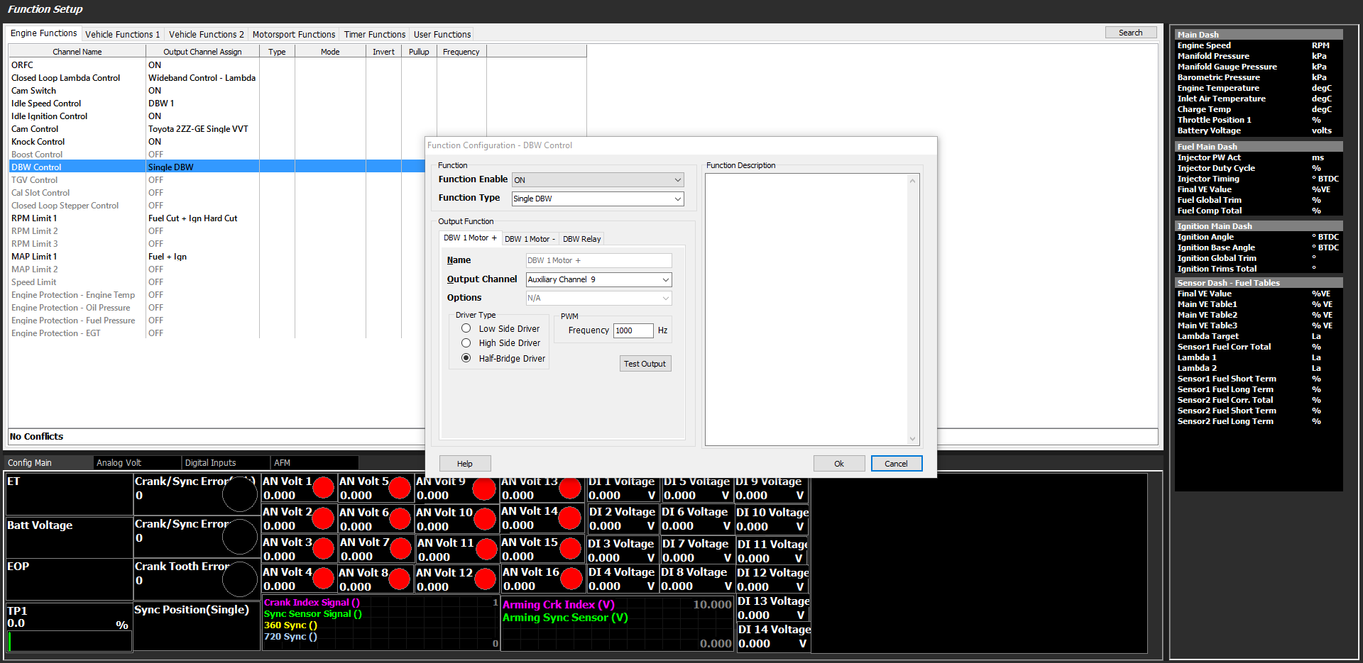
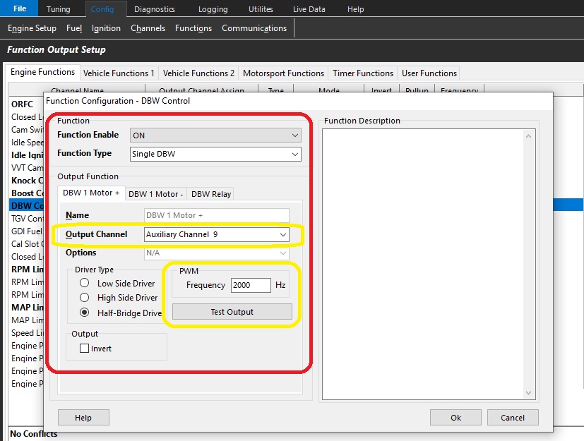
Below is an example of DBW function config.
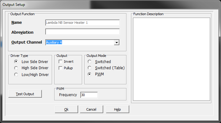
The mode for DBW is selected, the appropriate output channels, driver type (half bridge), and output frequency.
The same setup is required for any other functions that require outputs.
**See help file for specific functional setup
Communication
This section allows for setup using the Emtron CAN bus channels (2) regarding communication between auxuiliary devices such as dash systems, loggers, EGT devices, as well as Emtron CAN devices (ELC – Emtron Lambda controller).
Besides simple pre-configurations for standard logging sets, advanced setup of this system should be overseen by dealers/Emtron support. Contact your dealer or Emtron support for more assistance.
Continuous Logger
Continuous Logger
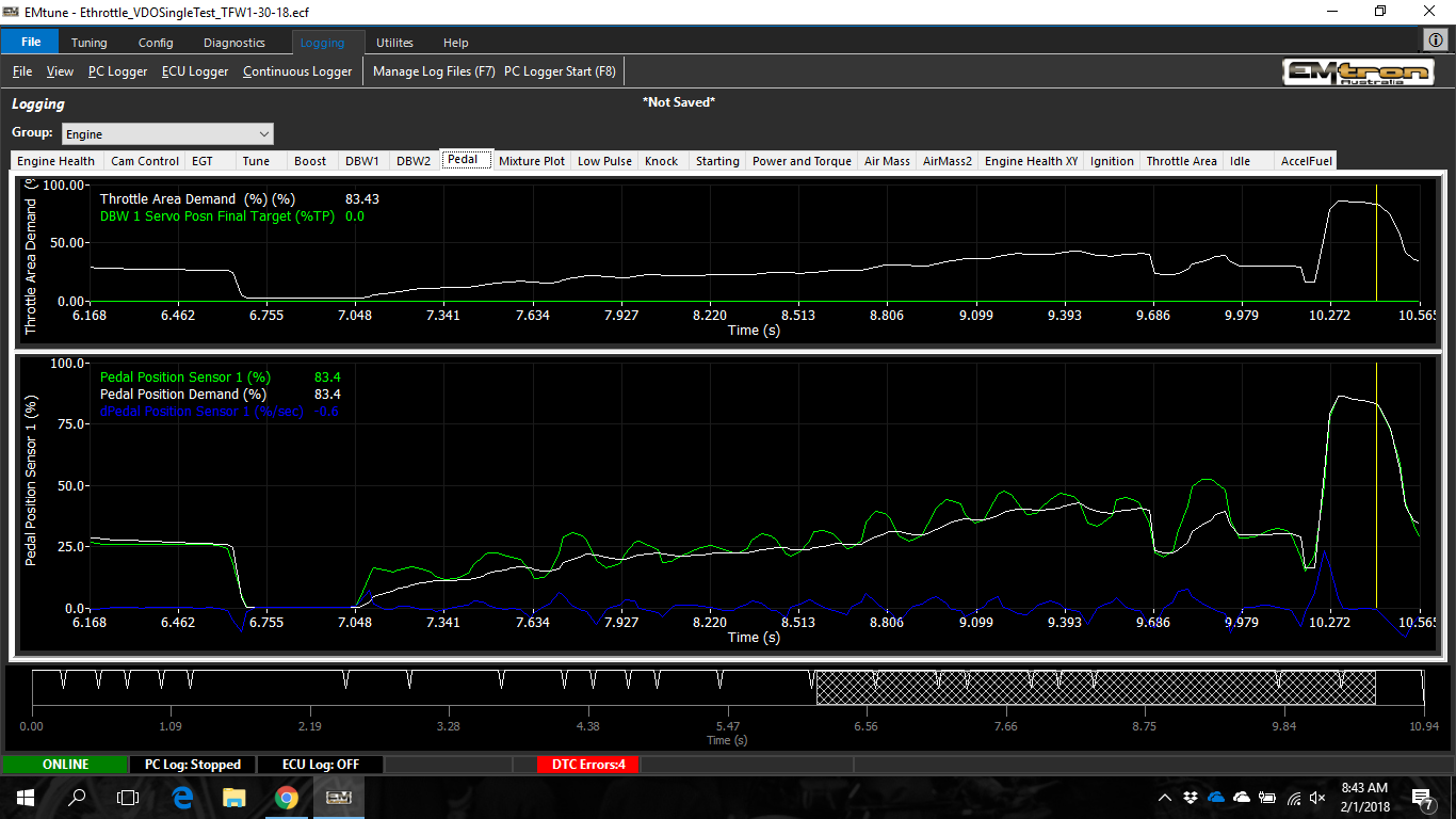
When connected to the ECU live, using the “P” key will “Pause” the software completely, and allow the user to navigate back a number of seconds using any line plots on the screen and see exactly where they were in the ECU software.
This mode acts as if they were live tuning the ECU in that very instant.
All hot keys such as “L”, “M”, or any other changes to the calibration are active during this mode, using the paused channel information available at that time.
ECU Password Protection
ECU Password Protection
All Emtron ECU’s have the ability to be locked to prevent access from others
This function is access through the main file menu
The Password Protected File cannot be viewed or recovered unless the correct password is known.
Removing Password Protection
If the password is known, this can be done through the main file menu using the Clear Password function
If the password is not know and cannot be retrieved and the ECU must be accessed; the following steps apply.
Sending a Calibration (Cal) File to a Password Protected (Locked) ECU
Any Cal file can be sent to a locked ECU.
Sending a file will load the new Cal file settings into the ECU.
Sending an alternative file will result in the removal of all current ECU settings including the existing password
(when enabled).
There are 2 possible conditions:
The Cal file being sent is Locked. The Cal file will be sent immediately to the ECU overwriting the current ECU file. After the download is complete and the ECU powered cycled the ECU will be locked and you will need the correct password to open the ECU.
The Cal file being sent is Unlocked. The Cal file will be sent immediately to the ECU overwriting the current ECU file. After the download is complete and the ECU powered cycled the ECU will be unlocked.
ECU Runtimes
ECU Runtimes
The ECU Runtimes can be accessed by pressed the F3 key or selecting the following menu item:
Emtune Dash Panel Configuration
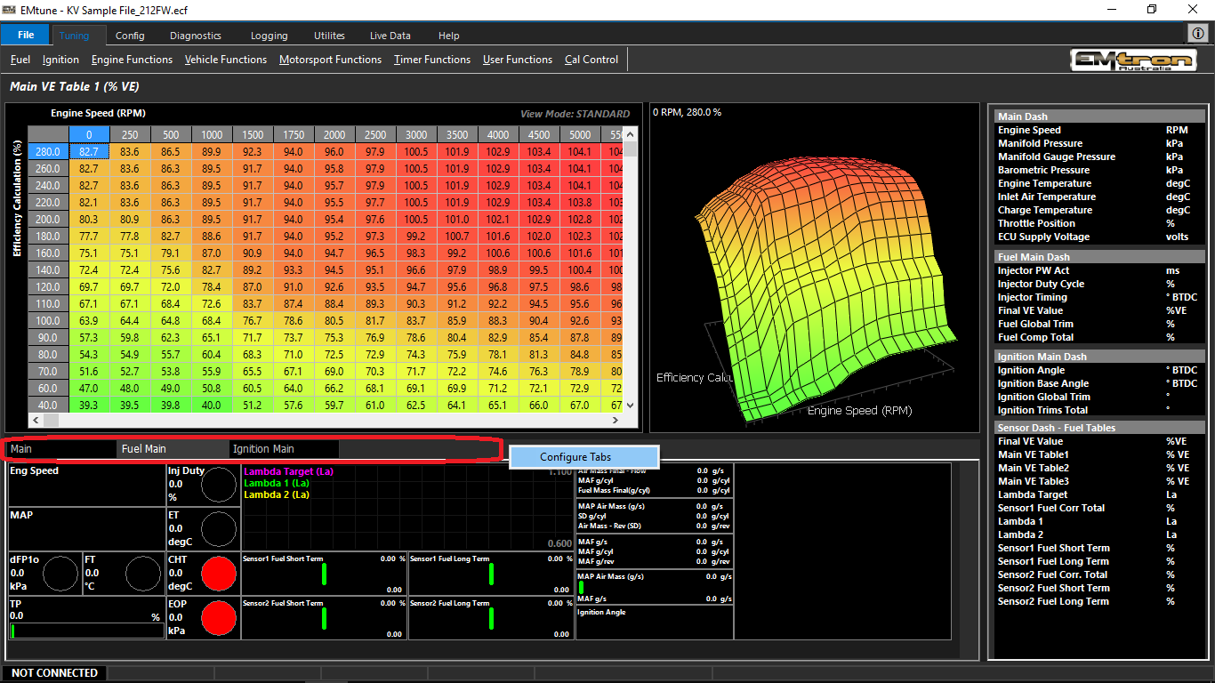
Emtune allows the user to customize the dash panel screens to suit their needs accordingly.
When opening Emtune for the first time (also when updating software versions), Emtune will ask if you want to overwrite the existing layouts for both the dash panels and the logger with new default configurations. Select accordingly.
Right Click the Tab section to select Configure Tabs to edit tabs and visibility:
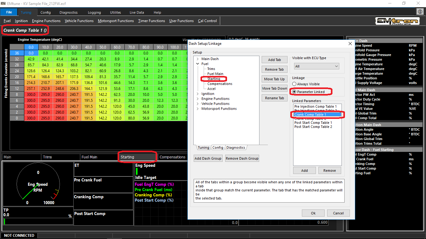
The dash panels are organized by Dash Groups located in the Setup section
** If a function in the software does not have linked view (see below), Main Dash, Main panel will be displayed.
In each dash group, tabs can be created which then can point a software function to that panel. To connect the software to that particular display panel, select Parameter Linked, then add the table to the list. The ECU will then always select that display tab when in the table being viewed (in the case below, Starting, Cranking Comp Table 1).
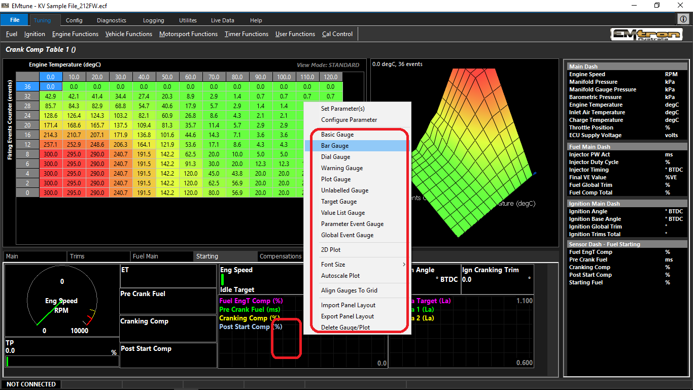
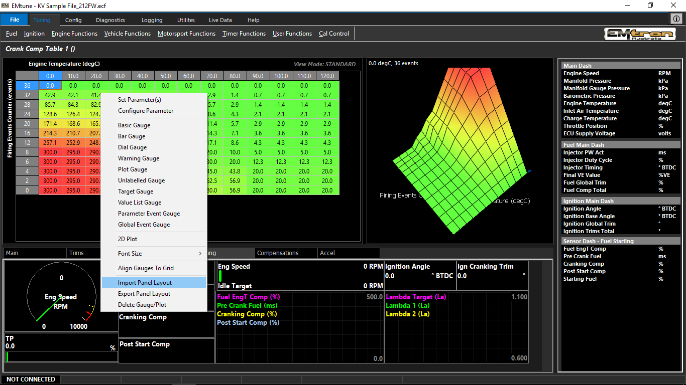
Right click the panel to change, edit, add, replace gauges in the active panel.
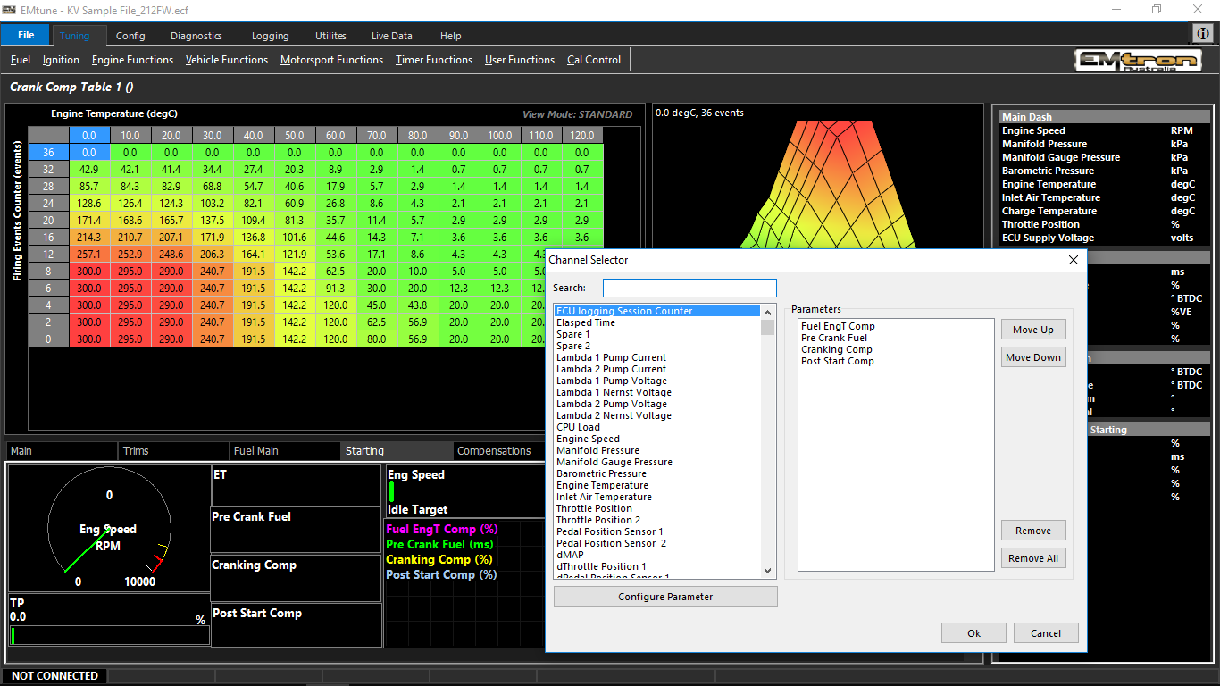
Set parameter allows you to define what runtime you want to display. In the case where the display gauge/plot can display more than one runtime, you can add multiple to the list
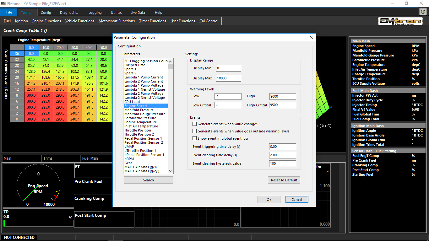
Configure parameter allows you to define the min/max scales for gauges, bar graphs, warning gauges, etc.
Each panel can individually be imported/exported at the bottom of the list when right clicking the panel
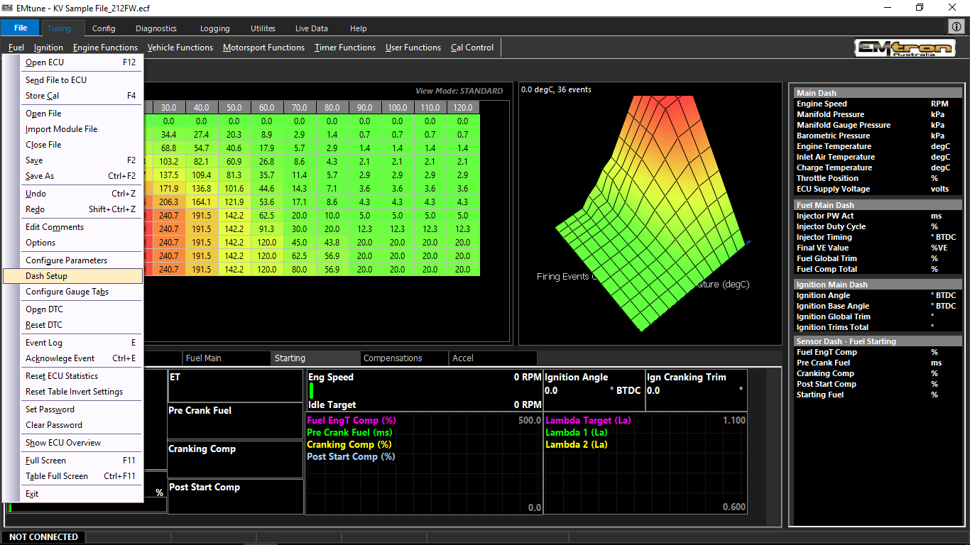
The entire dash layout can be imported and exported via that “Dash Setup” selection under the file menu.
** Periodically save your dash setup
Emtune Welcome Screen
Welcome Screen
When first opening Emtune software a Welcome Screen is displayed.
From here the user has several options in which they would want to use the connection to their PC.
This is one of the unique features to Emtron/Emtune as it eliminates many of the anxieties of connecting to ECU systems.
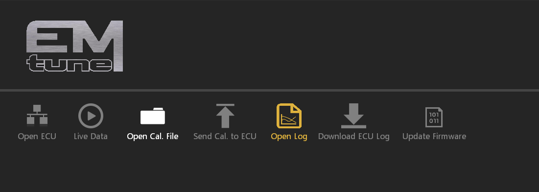
An end user can easily download an ECU log, or look at one way Live Data communication without actually opening the calibration file.
Open ECU
Only available when ECU is connected
Use this option to connect to the ECU to perform configuration, calibration, live PC data logging, scope functions, and more.
This is the main mode for live calibrating.
Tuning Tip: The Hot key to achieve connection / disconnection lieu of using the mouse is F12
Live Data
Only available when ECU is connected
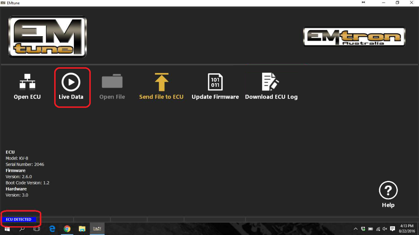
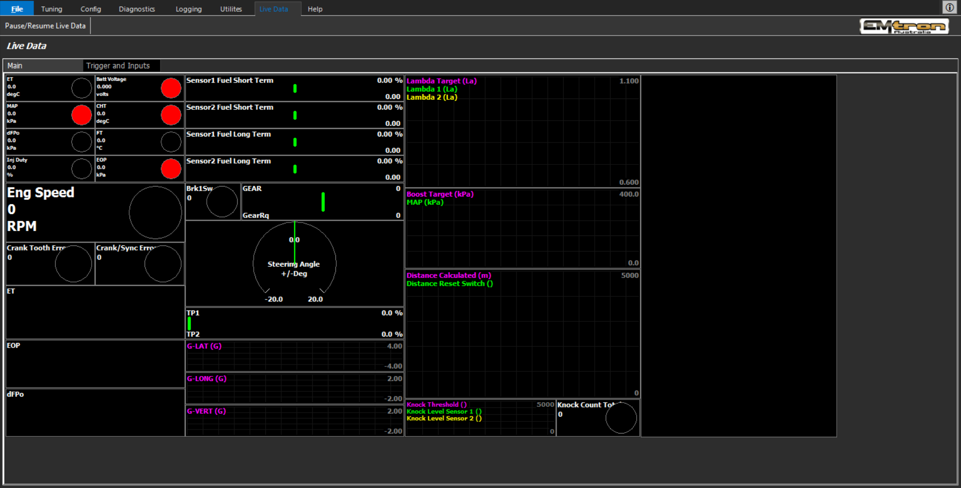
This option allows the user to connect to the ECU in a “one way” communication mode. The mode does not allow transmitting of any user settings that can change the calibration in any way. The live data display dashboards, runtime plots, gauges, pages, tabs, and more must be configured in the Open ECU/Open File modes. Generally this is performed by the dealer/installer/calibrator of the ECU as depending on the application the display changes may change. All runtime data is also available in the Live Data mode as well.
Open File
Available anytime the software is opened
This mode allows offline calibration editing, as well as configuration of the Live Data page.
Send File to ECU
Only available when ECU is connected
A previously saved calibration file (either from live calibrating, or offline editing) can be sent and stored to the ECU with this option. This allows the user to update the calibration file without having to open the ECU.
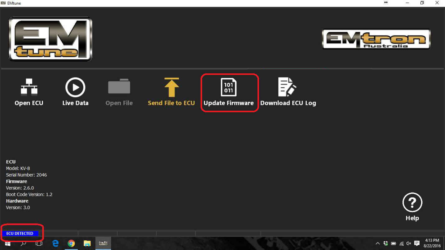
Update Firmware
Only available when ECU is connected
Use this function to update the ECU Firmware.
CautionThis procedure should only be done by authorized dealers unless under strict instruction to do so otherwise. The ECU should have a stable power source during updating as it takes up to 25 min to complete.
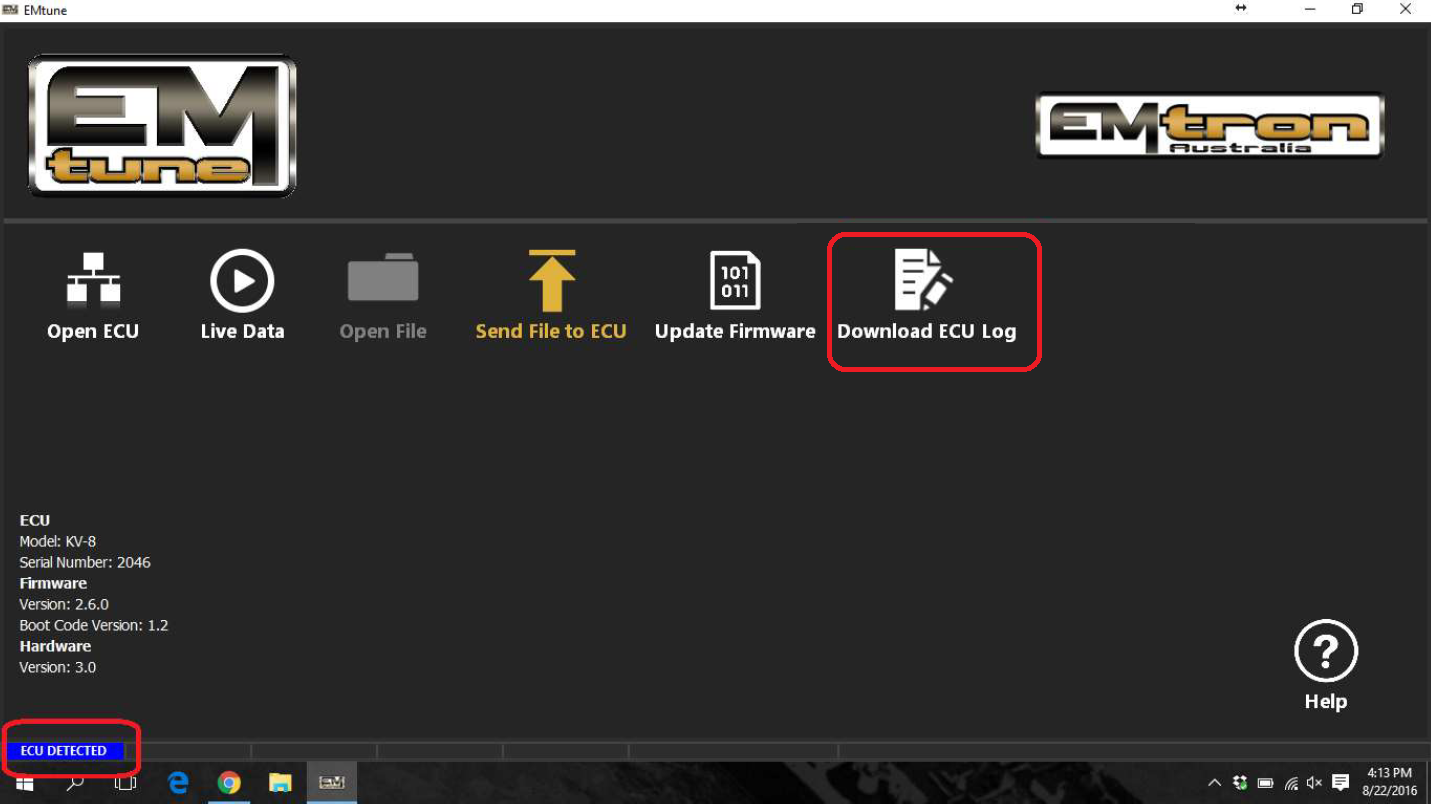
Download ECU Log
Only available when ECU is connected
This function downloads the ECU log. The ECU logging function is configured in the Open ECU/Open File mode inside the calibration file.
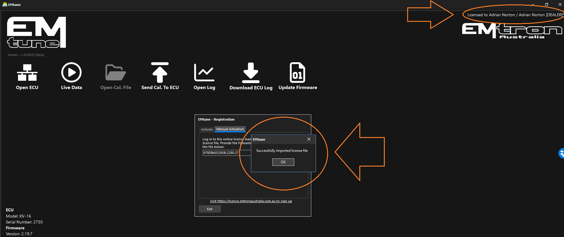
Licence Expired
Licence Expired
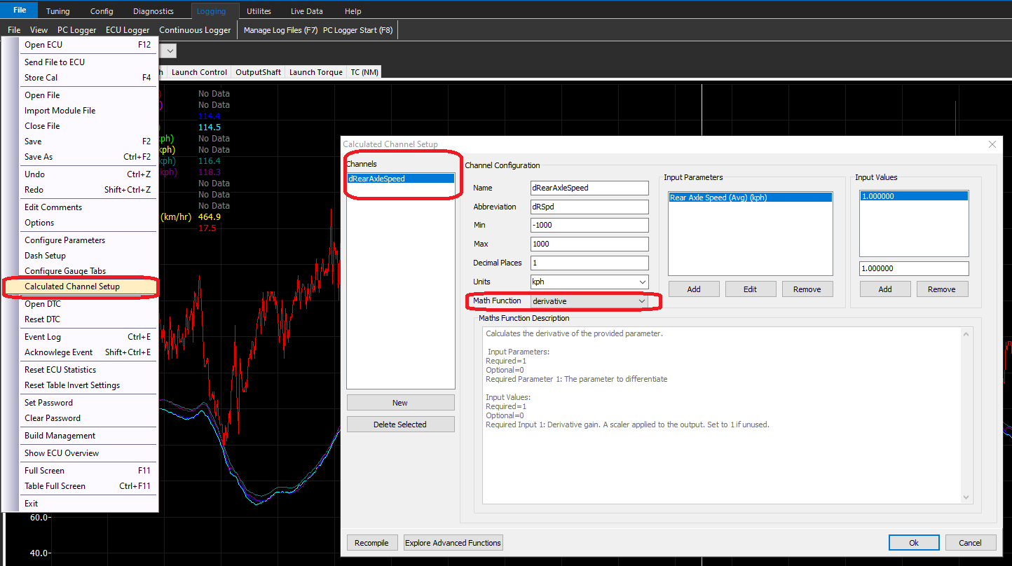
Math Expressions
A user definable mathematical equation that allows the user to generate channels for data analysis or to aid in rapidly validation tuning data. The expression is defined by a single line of text that can include most common mathematical operations and many advanced functions.
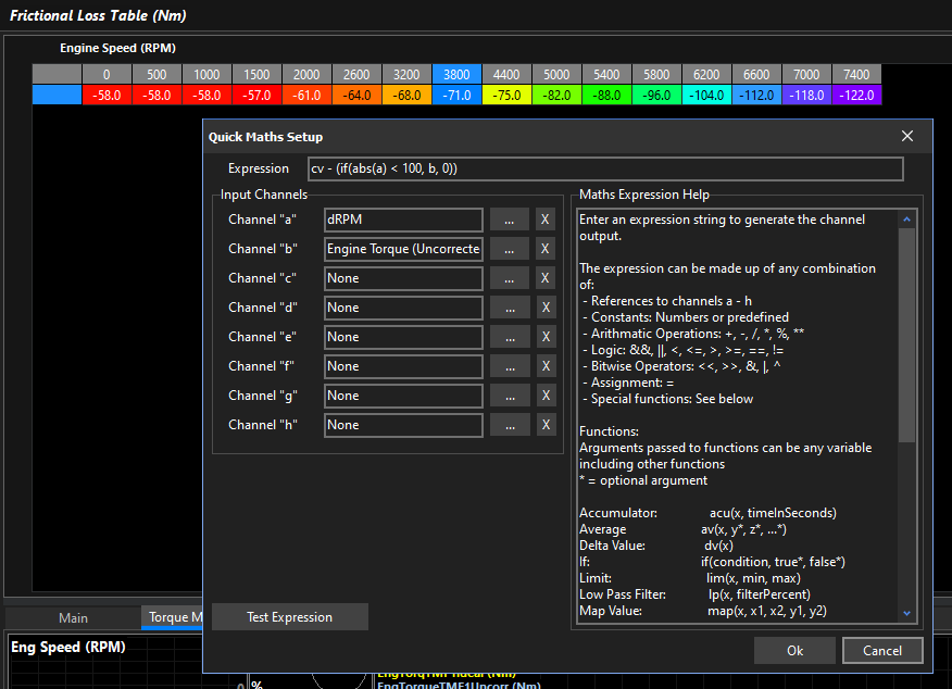
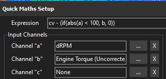
In the above example, the expression cv - (if(abs(a) < 100, b, 0)) is used.
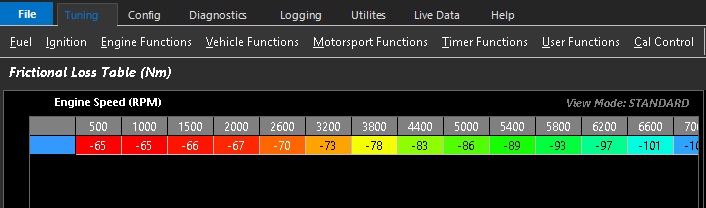
When the Q key is pressed, the expression takes the current table cell value cv and subtracts Engine Torque (Uncorrected) b, but only if the absolute Derivative Engine Speed a is less than 100 RPM/s, otherwise it subtracts nothing. This means it will automatically fill in the frictional loss table for you but it makes sure the engine speed is stable.
Syntax
Spaces are ignored by the compiler and can be omitted or included to improve readability. There is no difference to the result.
Operator / Character
Description
Usage
Example
Result
Arithmetic
+
Add
x + y
12 + 3
15
-
Subtract
x - y
12 - 3
9
*****
Multiply
x * y
12 * 3
36
/
Divide
x / y
12 / 3
4
%
Modulus / Remainder
x % y
12 % 3 12 % 10
0 2
******
Power
x ** y
12 ** 3
1728
Logical
<
Less Than
x < y
12 < 3 12 < 34
0 (false) 1 (true)
>
Greater Than
x > y
12 > 3 12 > 34
1 (true) 0 (false)
==
Equal To
x == y
12 == 3 12 == 12
0 (false) 1 (true)
!=
Not Equal To
x != y
12 != 3 12 != 12
1 (true) 0 (false)
<=
Less Than or Equal To
x <= y
12 <= 3 12 <= 34
0 (false) 1 (true)
>=
Greater Than or Equal To
x >= y
12 >= 3 12 >= 34
1 (true) 0 (false)
&&
And
x && y
12 && 3 1 && 0 0 && 0
1 (true) Both sides are non zero 0 (false) 0 (false)
**
**
Or
x
!
Negation
x = !y
x = !1 x = !0
x = 0 x = 1
Bitwise
«
Shift Left
x « y
56 « 2
224
»
Shift Right
x » y
56 » 2
14
&
Bitwise And
x & y
56 & 15
8
**
**
Bitwise Or
x
y
^
Bitwise XOR Bitwise Not (32 bit signed integer)
x ^ y ^x
56 ^ 15 ^56
55 -57
Other
=
Assignment
x = y
x = 5
Assigns value of 5 to variable “x”
,
Comma. Separates expressions or function arguments
x = y, x * z min(x, y)
x = 5, x * 2 min(12, 3)
10 3
Variables
The letters a through h can be user assigned to any loggable ECU runtime parameter. These variables can then be used anywhere in the expression. The user assigned variables are updated with the current parameter value every time the expression is evaluated.
Some other variables such as “pi” are pre-assigned for use in the expression.
Variable
Type
Note
User Variables
a
Assignable Input Parameter
b
Assignable Input Parameter
b
Assignable Input Parameter
c
Assignable Input Parameter
d
Assignable Input Parameter
e
Assignable Input Parameter
f
Assignable Input Parameter
g
Assignable Input Parameter
h
Assignable Input Parameter
Time
t
Time (seconds)
Calculated Channels Only
dt
Delta Time (seconds)
Calculated Channels Only
Constants
pi
Constant
Special
cv
Cell Value
Table Math Only. Represents the value of the table cell before any math operation is performed.
It’s possible to create and assign variables within the expression. This can be useful for breaking up the expression to make it more readable.
For example these two expressions are functionally equivalent:
cv *max(a, b, c, d)
m =max(a, b, c, d), cv * m
Here two separate operations are created and separated by the comma character. First a variable called m is created and assigned the result of the max() function. Secondly the table cell cell value cv is multiplied by m. As there is no more work to do the expression returns the result of the second operation which then gets passed to the table to be used.
Variables can remember their value between iterations:
x = x +1
The variable x is created and incremented by 1 every time the expression is evaluated.
y =5, x = x + y
The variable y is created and assigned the constant value of 5. With every evaluation, x is increased by the value of y which in this case is 5.
NOTE: The iterative nature of variables should be considered when writing expressions that may use them.
Functions
Functions are purpose built computational blocks that take input arguments to output a result. Functions are called by their name followed by brackets containing a list of arguments separated by commas. For example:
result =func(arg1, arg2, arg3)
Some functions take a single input argument, some take more. Arguments can be any other valid syntax type such as constants, variables, other functions or logic expressions.
See the table below for a list of the available functions and their usage.
*Optional Argument
Function Abbreviation
Full Name
Description
Arguments
Example
abs(x)
Absolute
Returns the absolute (positive) value of the input. Turns a negative value into a positive. Makes no change to a value that is already positive.
1. x Input value
abs(123) = 123 abs(-123) = 123
acu(x, t)
Accumulator
Time based average of 100 evenly spaced samples taken over the given time ’t’ in seconds.
1. x Input value 2. t Time (seconds)
acu(a, 10) Returns the average of the last 10 seconds worth of the variable ‘a’. Can be used to generate accumulated load values from parameters such as Manifold Pressure or Throttle Area Demand.
av(x, y, z, *…)*
Average
Averages the values of all given inputs. Requires 2 or more inputs.
1. x Input Value 1 2. y Input Value 2 3. zOptional. Input Value 3 And so on…
av(a, b) Returns the average of inputs ‘a’ and ‘b’. av(a, b, c, d, e, f) Returns the average of inputs ‘a’, ‘b’, ‘c’, ’d’, ’e’, ‘f’. av(123, 45, 67) Returns 78.333
dv(x, ti)
Delta Value
Calculates the rate of change in the input value over per second. Samples are taken at the specified time interval. The output is expressed in units per second.
1. x Input Value 2. ti Time Interval (seconds)
dv(a, 0.2) Suppose ‘a’ was 10 at the previous sample. Now, 0.2 seconds later the value of a is 15. ‘a’ has changed by +5 over 0.2 seconds. The result will be 5 / 0.2 = 25 or 25 units per second.
if(cond, true, false)**
If
Performs Logical evaluation and either outputs a boolean (0 or 1) result or it outputs the optionally provided true/false values. The function checks the value of the first argument (cond). If the value is greater than 0 then it will either return the value passed in to the second argument (true) or 1. If the cond value is 0, then it will either return the value passed in to the third argument (false) or 0.
1. cond Input condition. Can be any variable, function or logic expression. 2. true Optional#8202;.* This value is returned by the if() function when the input condition evaluates to greater than 0. If a true argument is not provided, the true result defaults to 1. 3. false* Optional. This value is returned by the if() function when the input condition evaluates to zero. If a false argument is not provided, the false result defaults to 0.
if(a > b) Only argument 1 provided. If the value of channel ‘a’ is greater than the value of the channel ‘b’ then the function will output 1, else it will output 0. if (a, b) Arguments 1 & 2 provided. If the value of channel ‘a’ is greater than 0, then the result will be the value of channel ‘b’, else 0 (as no 3rd argument for false is given). if(a ** 2 == 9, 10, b + 1) Arguments 1, 2, & 3 provided. If the value of the channel ‘a’ squared is equal to 9, then the result is 10, else the result is the value of channel ‘b’ plus 1.
lim(x, min, max)
Limit
Clamps the input value to the given range limits.
1. x Input Value 2. min Minimum allowed output 3. max Maximum allowed output
lim(a, 10, 90) If ‘a’ is less than 10, the output will be 10. If ‘a’ is greater than 90, the output will be 90. If ‘a’ is within the range of 10 to 90, the output will be ‘a’ unchanged.
lp(x, α)
Low Pass Filter
A simple low pass filter. Output = (α % of the filtered value) + (100 - α % of the new value)
1. x Input Value 2.α Alpha (%)
lp(a, 85) Suppose ‘a’ has a current filtered result of 95. Now the filter is given the new value of 100. The new filtered result = (95 * 0.85) + (100 * 0.15) = 80.75 + 15 = 95.75. The filter will now store 95.75 as the previous result and return 95.75 as the output. If the input was to stay at 100, after several iterations the output will arrive at 100 also.
map(x, x1, x2, y1, y2)
Map / Interpolate
Linearly Maps/Interpolates the input value to a new range of output values. For example if x values are voltage and y values are percentages, the function would interpolate the input voltage to the spanned output percentage.
1. x Input Value 2. x1 Input Range Position 1 3. x2 Input Range Position 2 4. y1 Output Range Position 1 5. y2 Output Range Position 2
map(a, 0.5. 4.5, 0, 100) If ‘a’ is 0.5, the output will be 0. If ‘a’ is 4.5 the output will be 100. If ‘a’ is 2.0, the output will be 37.5. If ‘a’ is 0.2 the output will be -7.5. If ‘a’ is 4.8 the output will be 107.5.
mapl(x, x1, x2, y1, y2)
Map / Interpolate (Limited)
Similar to map() however the output result is clamped to the y1, y2 range limits.
1. x Input Value 2. x1 Input Range Position 1 3. x2 Input Range Position 2 4. y1 Output Range/Limit Position 1 5. y2 Output Range/Limit Position 2
mapl(a, 0.5. 4.5, 0, 100) If ‘a’ is 0.5, the output will be 0. If ‘a’ is 4.5 the output will be 100. If ‘a’ is 2.0, the output will be 37.5. If ‘a’ is 0.2 the output will be 0. If ‘a’ is 4.8 the output will be 100.
max(x, y, z, …*)*
Max Value
Returns the highest of any of the given input values. Requires 2 or more inputs.
1. x Input Value 1 2. y Input Value 2 3. zOptional. Input Value 3 And so on…
max(a, b) Returns the maximum of inputs ‘a’ or ‘b’. max(a, b, c, d, e, f) Returns the maximum of inputs ‘a’, ‘b’, ‘c’, ’d’, ’e’, ‘f’. max(123, 45, 67) Returns 123
min(x, y, z, …*)*
Min Value
Returns the lowest of any of the given input values. Requires 2 or more inputs.
1. x Input Value 1 2. y Input Value 2 3. zOptional. Input Value 3 And so on…
min(a, b) Returns the maximum of inputs ‘a’ or ‘b’. min(a, b, c, d, e, f) Returns the maximum of inputs ‘a’, ‘b’, ‘c’, ’d’, ’e’, ‘f’. min(123, 45, 67) Returns 45
sqrt(x)
Square Root
Calculates the square root of the input value.
1. x Input Value
sqrt(a) Returns square root of a sqrt(123) Returns 11.0905365
sin(x)
Sine
Calculates the Sine of the input value.
1. x Input Value
sin(a) Returns sine of a sin(123) Returns 0.83867
cos(x)
Cosine
Calculates the Cosine of the input value.
1. x Input Value
cos(a) Returns cosine of a cos(123) Returns -0.544639
tan(x)
Tangent
Calculates the Tangent of the input value.
1. x Input Value
tan(a) Returns tangent of a tan(123) Returns -1.539865
Examples
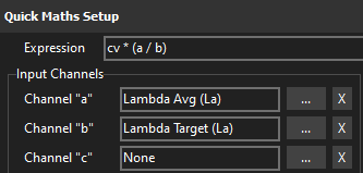
VE Table Quick Validate
cv * (a / b)
a = Lambda Avg
b = Lambda Target
This is equivalent to the operation performed when pressing the L key during live tuning. The advantage here is that the the expression can be performed using the the current log cursor position values as inputs.
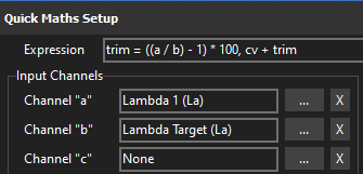
Bank 1 Trim Table Quick Validate
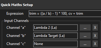
trim = ((a / b) -1) *100, cv + trim
a = Lambda 1*
b = Lambda Target*
Similar to the VE expression except that it gives a percentage offset value to be used in the bank trim table. Assumes Bank 1 is measured by Lambda 1.
First the trim is calculated, then the trim is added to the cell value
Bank 2 Trim Table Quick Validate
trim = ((a / b) -1) *100, cv + trim
a = Lambda 2
b = Lambda Target
Similar to the VE expression except that it gives a percentage offset value to be used in the bank trim table. Assumes Bank 2 is measured by Lambda 2
Frictional Loss Table
cv - (if(abs(a) <100, b, 0))
a = dRPM
b = Engine Torque (Uncorrected)
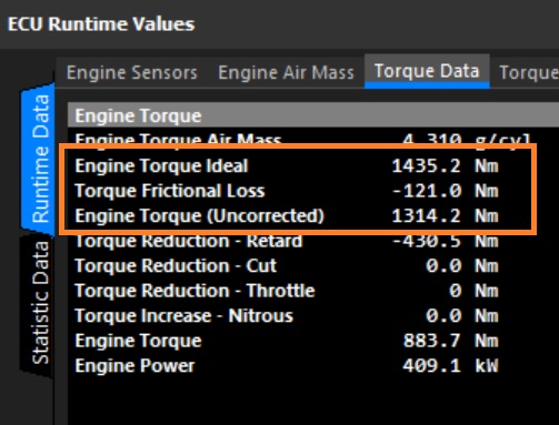
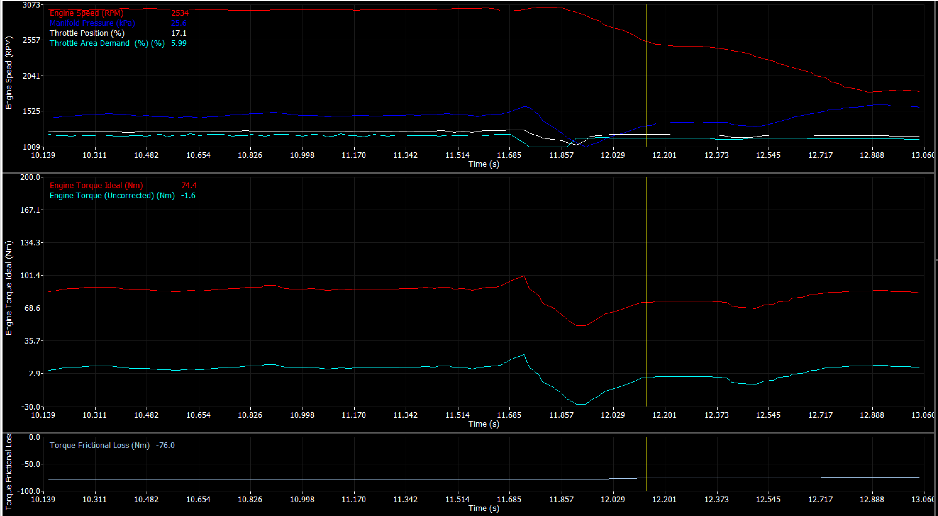
When the engine is accelerating, torque is positive. When the engine is decelerating torque is negative. When the the engine speed is stable (unloaded free revving) the torque is 0. The frictional loss table is used to account for the internal drag of the engine rotating assembly in order to give the correct 0mn final torque value.
The expression checks the dRPM to make sure the engine is held at a near constant RPM (less than a generous 100 rpm/s in this example) where final torque should be 0nm. The abs() function is used to turn a negate dRPM value into a positive to simplify the < (less than) logic. If the dRPM check is true, the current Engine torque value is subtracted from the cell value, if not 0 is subtracted from the cell value, ie. nothing happens.
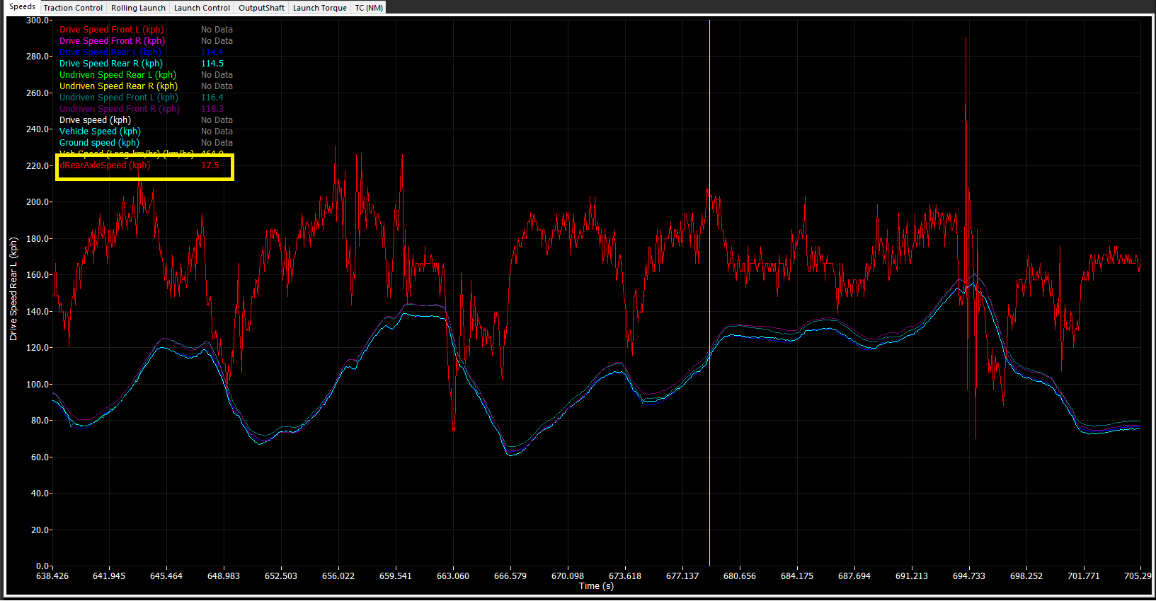
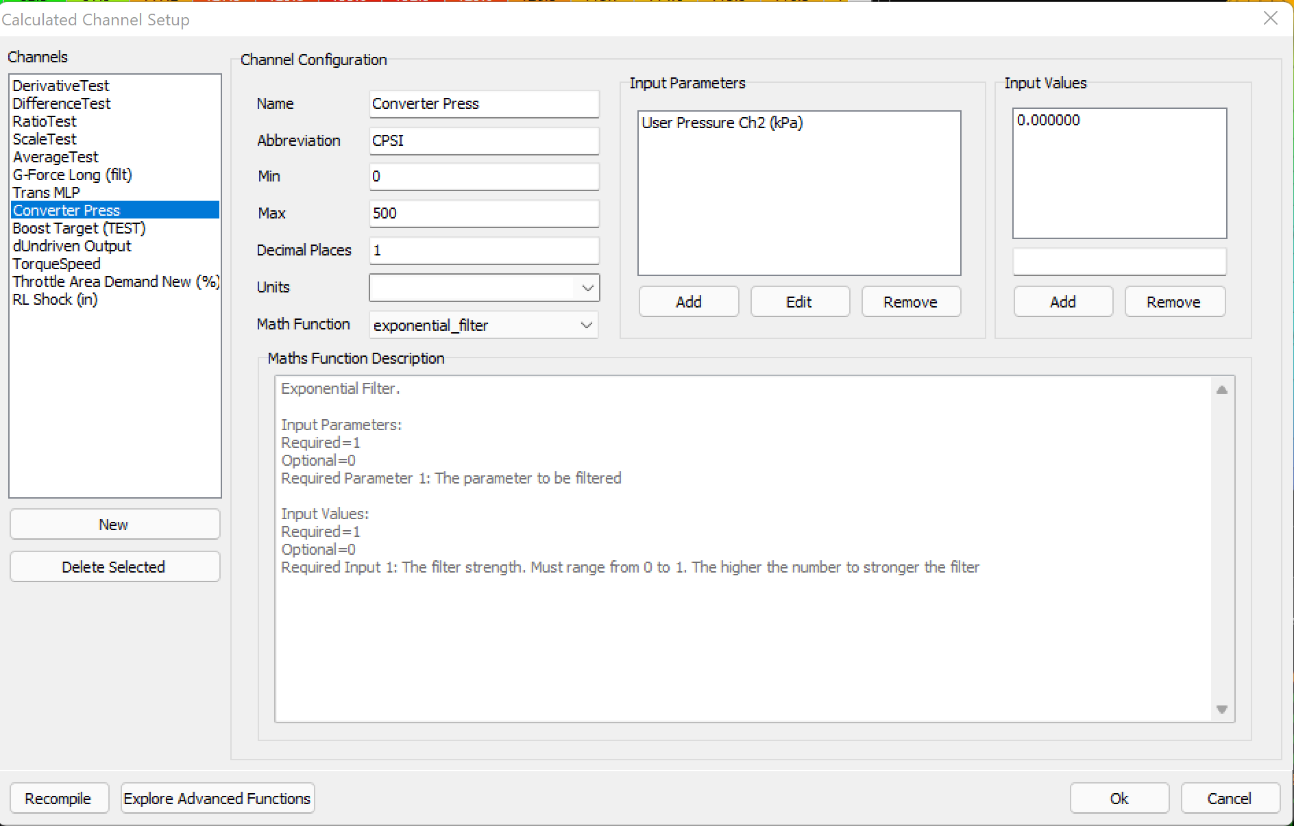
Calculated Channels
Extreme Example: Knock Threshold Level Helper
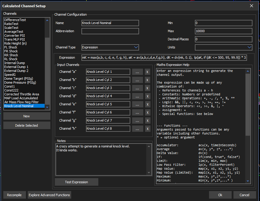
mK =max(a,b,c,d,e,f,g,h), aK =av(a,b,c,d,e,f,g,h), dK =dv(mk, 0.1), lp(aK, if (dK <=500, 95, 99.9)) *3.2
a - h = Knk Level Cyl #
An example of using some nested expressions to generate a bit of an idea of what the ideal knock threshold value might be.
The expression finds the max knock (mK), then the average knock (aK), then the derivative of the max over 100ms. Next applies a low pass filter over the average, and adjusts the filter level depending on the derivative. Finally it multiplies the result by 3.2.
This is an example only and isn’t intended to be useful as is for any or all applications. It does however show how functions and variables can be nested in a variety of ways.
Store Cal (F4)
The Store Cal function stores the Cal File to the ECU permanently.
It is also accessible by the F4 hotkey or from the File Tab.
Warning: Failure to Store Cal after making changes will result in lost of data.
Tips & Tricks
Tips on Improving your Emtune tuning efficiency…
Methods of validating VE Table
Auto Lambda Correction:
Utilise “L” Auto Lambda Correction feature of the software.
“L” applies current Lambda Target Error % to live location in map automatically.
Manual Entry Lambda Correction:
Using “M” key “Manual Entry Lambda correction method”.
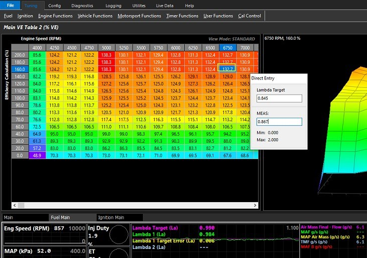
“M” is pressed & the Lambda target value is imputed together with the measured value. Enter and the result is applied to the highlighted cell.
Direct Entry Lambda Correction
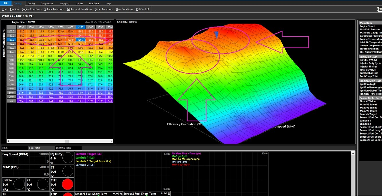
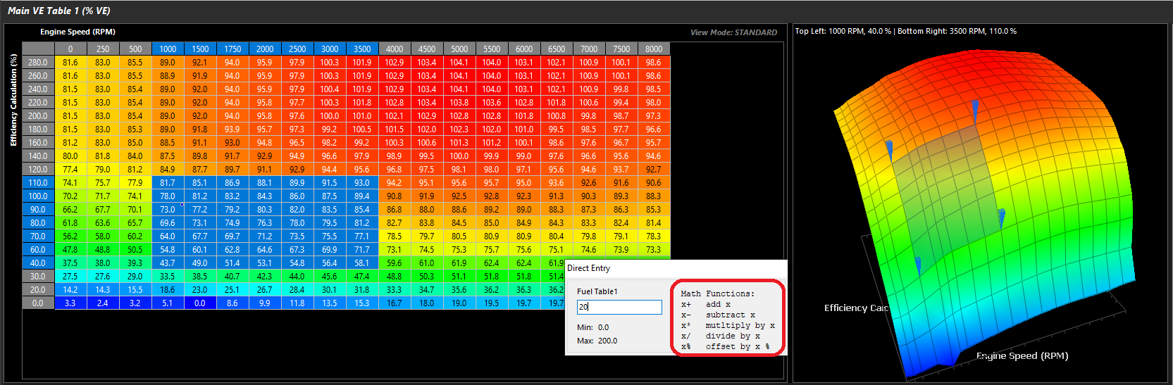
The maths value supplied in the target error runtime can be applied to the VE table as you would when using an excel spreadsheet, thereby correcting it. The table is highlighted & the correction manually entered.
Direct entry VE Correction Manual Maths examples:
Rich condition:
Lambda target: 0.864
Lambda 1: 0.782
Lambda Target error: 0.082
Highlight the cell to be corrected – Type 1.082 “/ “
Positive target error = division factor
Lean Condition:
Lambda target: 0.845
Lambda 1: 0.902
Lambda Target error: -0.057
Highlight the cell to be corrected – Type 1.057 “*” (Shift 8)
Negative target error = multiplication factor
Your goal should be to efficiently eliminate or minimise the error between the VE table & the Lambda target table.
Tip: To use this feature & validate the VE table, alter the dashboard to show not only the Lambda Target and Lambda 1/2, but also the Lambda Target Error.
Utilising “P” key (Pause)
Tuning tables can be quickly validated by utilising the “P” key to pause the live logging in the dashboard independent of the PC logging. This will allow you to drive through an area of a particular table, press “P” & then come back & edit where you have been.
Double clicking the mouse over the desired dashboard runtimes will allow you to move left & right through the paused data using the left & right arrow keys & will also highlight (overlay) the cells referenced in the table being validated.
“L”, “M”, and Table Maths are all available and usable as if being utilized “live” wherever the cursor is “paused”
Live logging recommences when “P” is pressed for the 2nd time.
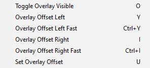
Utilising “O” Toggle Logger Position (The Yellow Box)
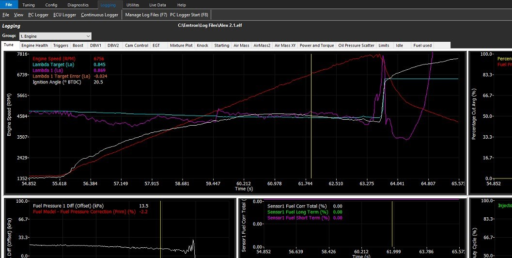
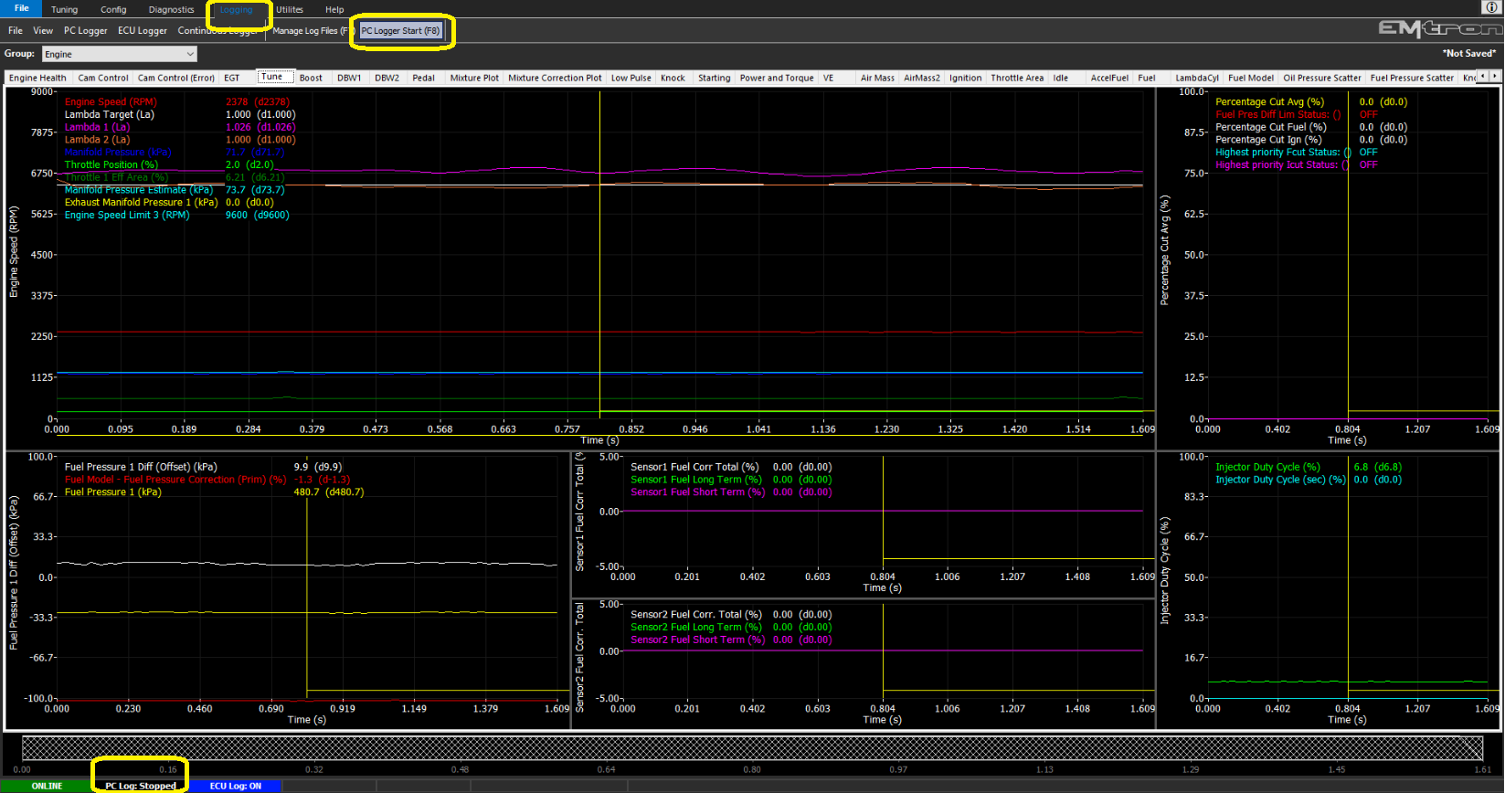
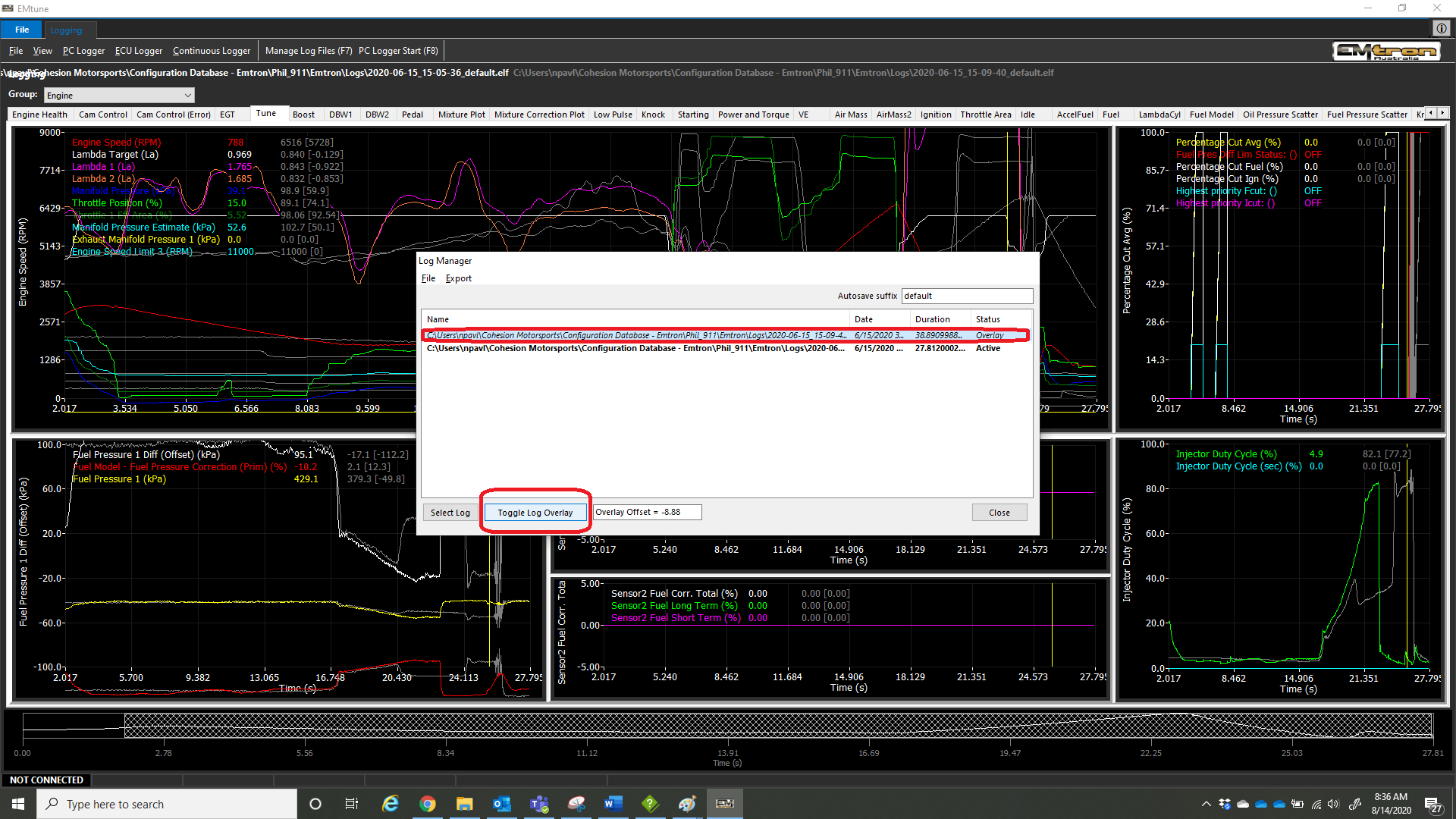
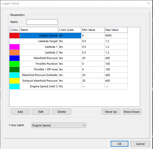
Using the PC logger (F8) the tune can be interrogated against target tune parameters.
Note: Setup your logger view to show the Lambda Target Error not found in default logger layout.
Once an area has been identified that needs attention.
The cursor is moved to highlight this area.
Returning to the referenced VE table in the tuning software.
Pressing “O” will toggle the yellow box over the referenced cell/s.
Lambda vs Lambda target can be utilised via “M” - Manual entry lambda correction.
Or direct entry method can be utilised.
Working example:
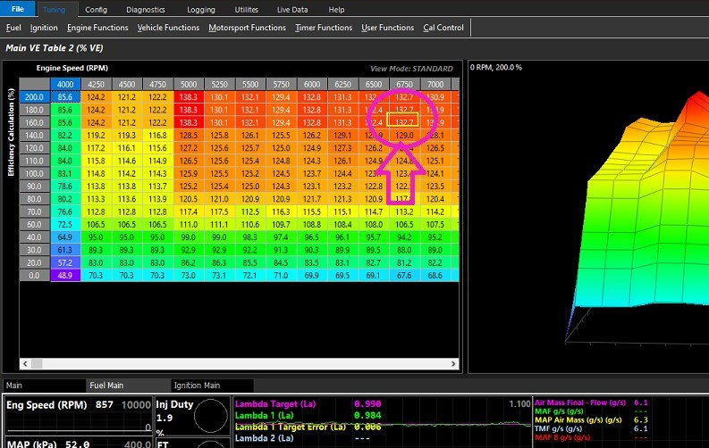
Lambda Target is 0.845
Lambda 1 (La) is 0.867
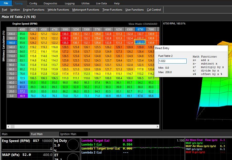
Lambda 1 Target Error (La) is -0.022 % (Lean)
To correct the table simple left mouse, click the referenced cell
Start typing 1.022* (shift 8)
This multiplies the missing percentage of fuel into the VE table thereby validating the table.
Maths values are explained in dropout box once typing commences.
(Rich values are divided)
Your goal should be to efficiently eliminate or minimise the error between the VE table & the Lambda target table.
Utilising “Scatter Plot” Correction
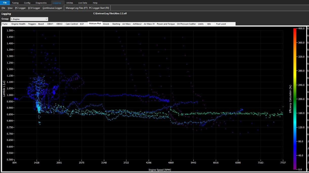
A useful feature of the Emtune logging is the Mixture Scatter Plot.
This is an often overlooked powerful and accurate tool for validating your VE table/s.
By utilising the features of the setup, this table can be utilised as a form of histogram of engine operation.
Note: Scatter plot correction applications are not limited to only VE tables. This method of validation is easily applied to bank trims & more.
Example: Lambda 1 active / Lambda control off
Validation performed on chassis dyno
VE Table for purpose of demonstration
The vehicle is driven and a PC log is produced recording the activity
Raw scatter plot is produced
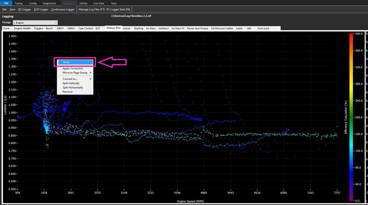
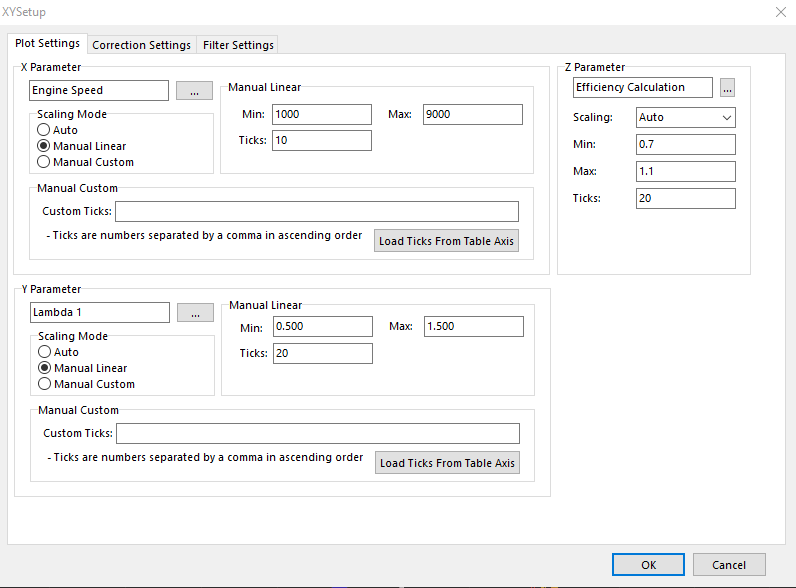
Enter the Scatter Plot Setup (Right Mouse Click)
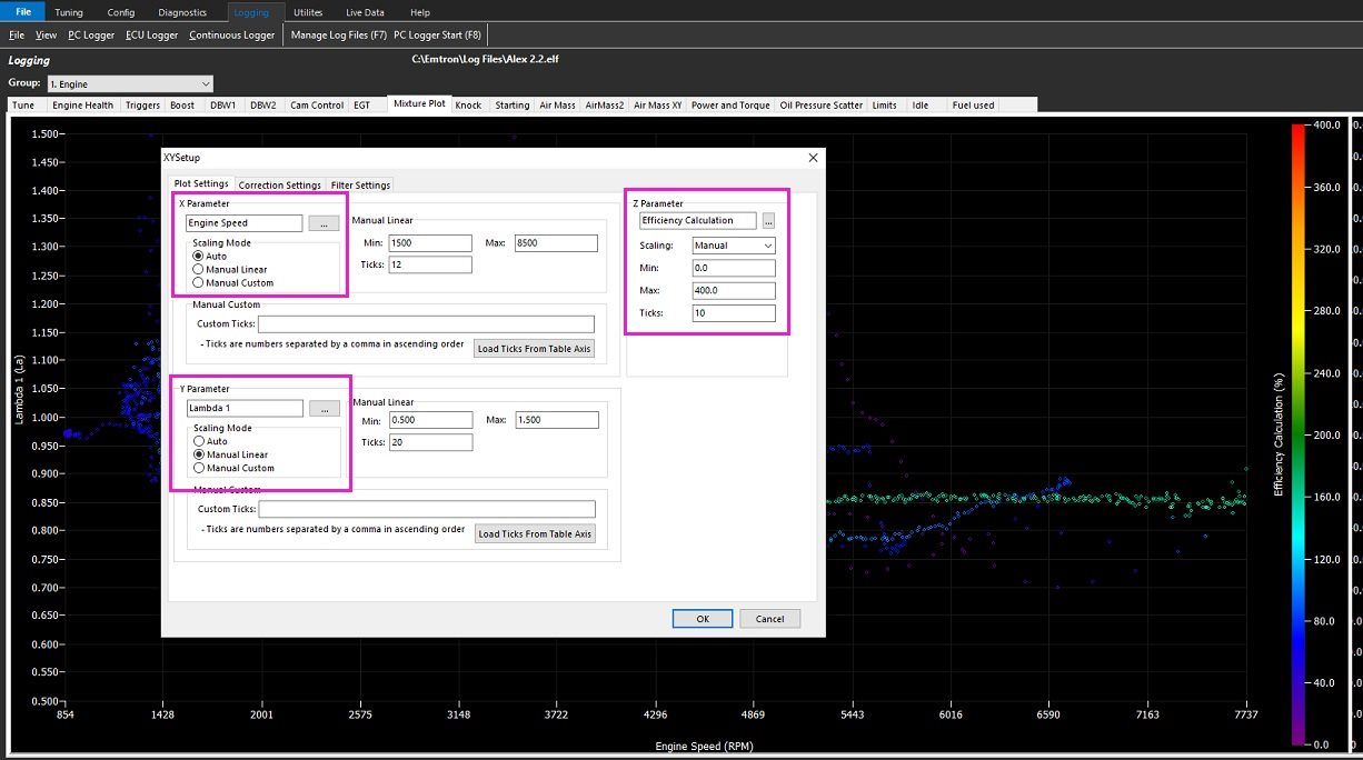
Confirm Plot Settings
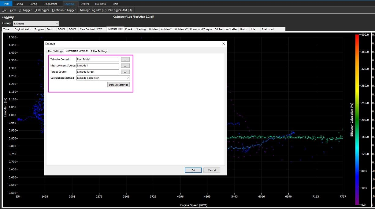
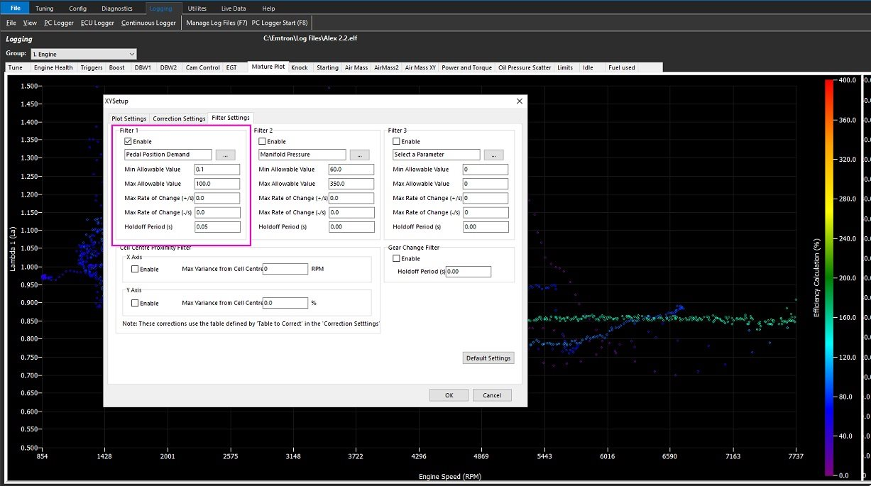
Confirm Correction Settings
Set appropriate filters as required
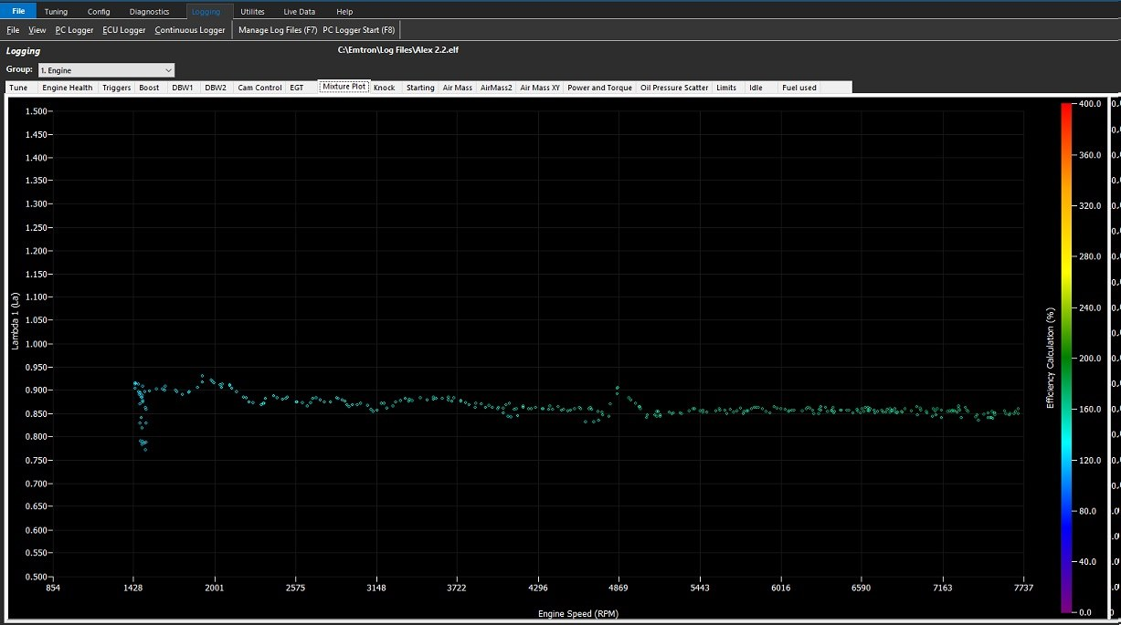
Return to the filtered scatter plot
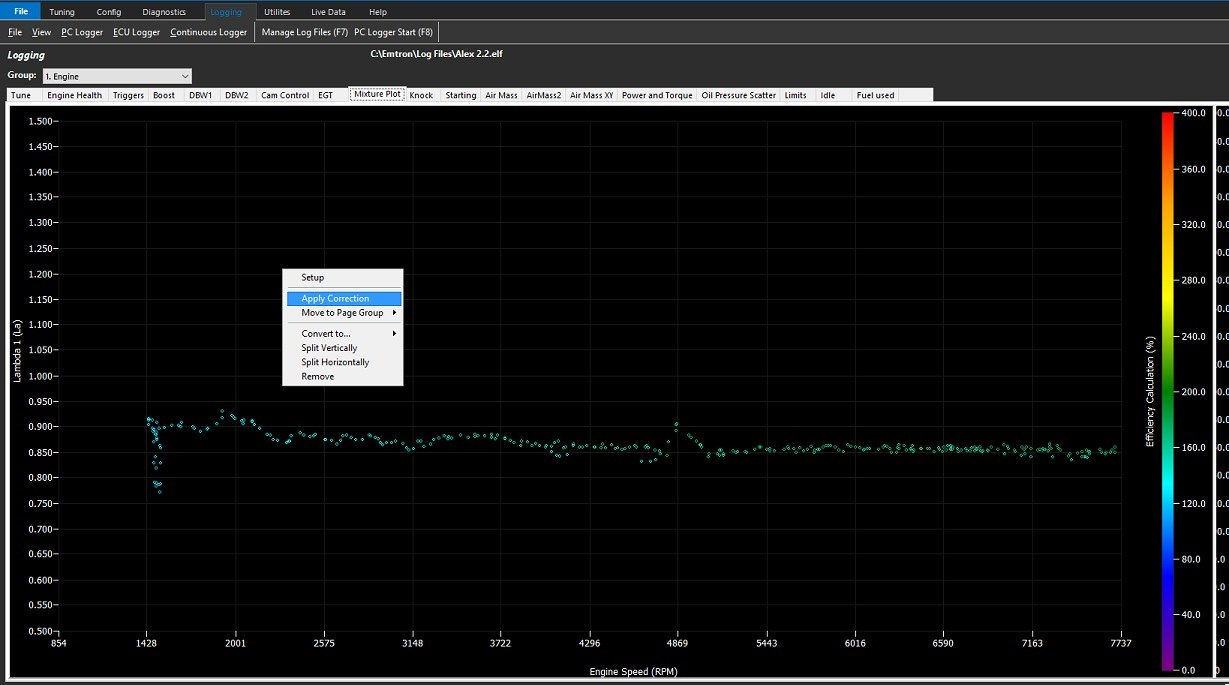
Apply the correction
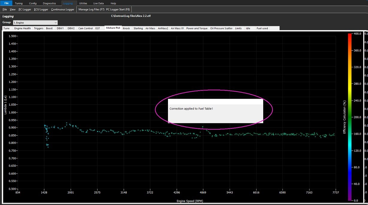
Emtune with acknowledge when this is complete
Tuning
Software Navigation
From the Welcome Screen, selecting Open File, or Open ECU (ECU Detected is required) the calibration file will be opened.
From here, you can navigate through a number of menus, tabs, sub tabs, etc.
The Emtune software has a very systematical approach to configuration.
Start on the left side, and work your way over from left to right.
Do not skip sections. Following this practice as accurately as possible will ensure tuning process will move smoothly in the future.
** Tuning should only be done once Basic Configuration and ECU Setup is complete (Config) - See Basic Configuration
*** If Tuning Functions are not available, it is due to the Configuration not being completed (see Config)
Table tools/maths
Several hotkeys and shortcuts are available in all tables to make management of entering values quick and easy.
Hotkeys PgUp/PgDwn will increase and decrease cells. Holding shift key will increase/decrease values faster.
Using the mouse, you can select multiple cells, to change multiple cells at a time, or use the keyboard while holding the CTRL key.
With cells selected, you can:
Increase/Decrease incrementally using PgUp/Down (holding shift key will increase/decrease values faster)
Interpolate between cells using keys I, R, C (I will interpolate diagonally, R horizontally - row, C vertically - column)
Or use table maths. Typing numbers into the keyboard will allow you to add, subtract, multuply, divide, or increase/reduce %.
Selecting a lot of cells, also holding the CTRL key, allows you to drag them around with the arrow keys to move them around the table (so easily move a line/section around the map).
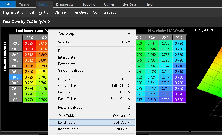
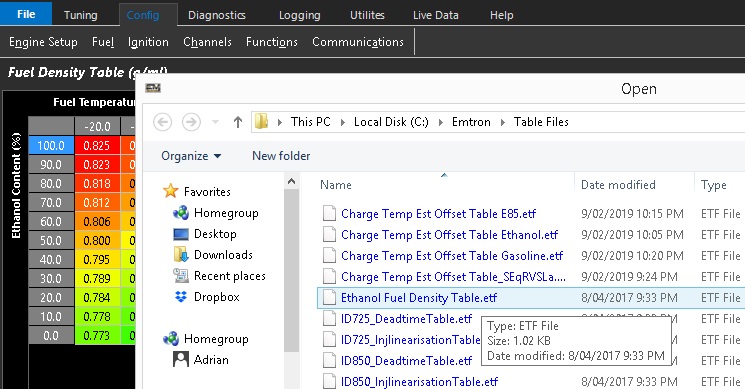
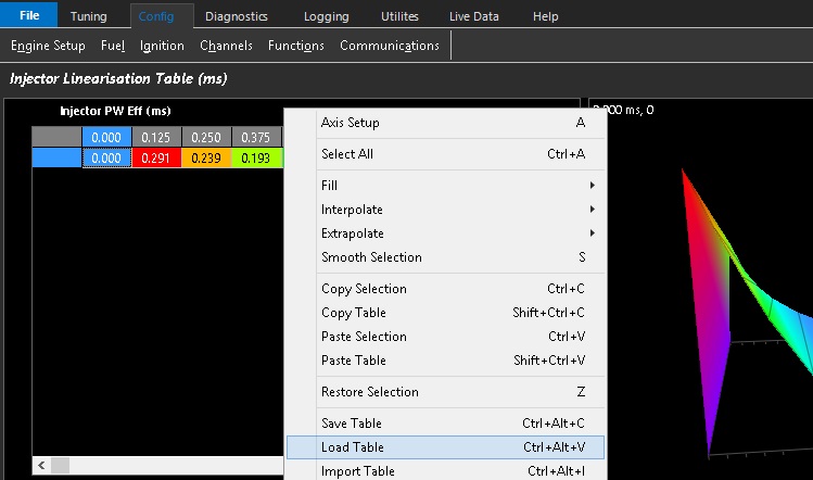
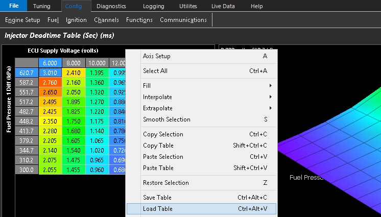
Right clicking the table shows options for hot keys mentioned above, but also the ability to Save Table externally, Load table from a separate file, but also import table.
Importing a table allows you to select another calibration file, and the software will reference the cal file selected, and grab the table from that location for the current working cal file.
This is a useful tool when building new calibrations if the user is trying to bring over certain tables that mostly will cross over.
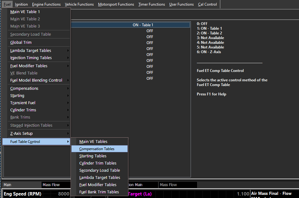
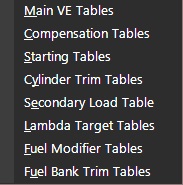
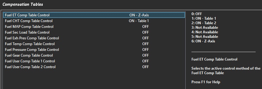
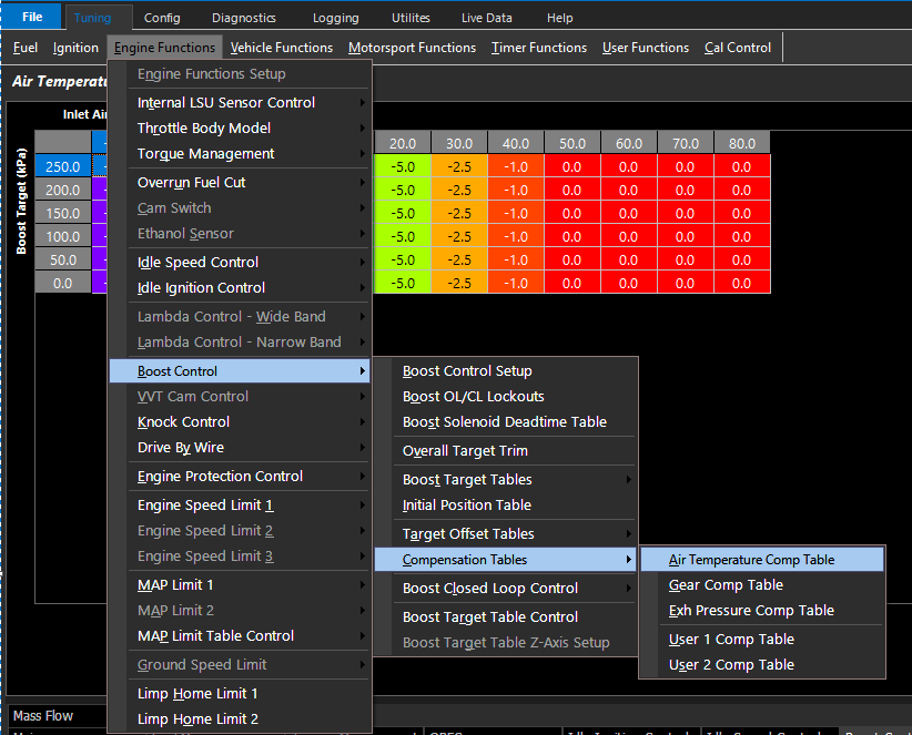
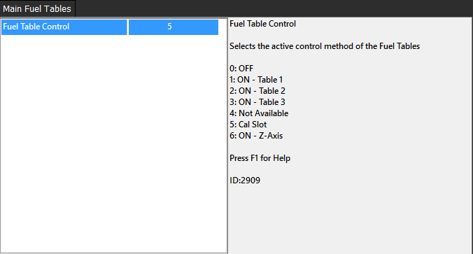
**** If Compensation (or other) Tables are not available, they must be enabled within the specific sub menu -> Fuel -> Fuel Table Control
Fuel
Fuel section allows the user to tune multiple tables for air flow , user compensations, air and fuel mass modifiers, Lambda Target, and more.
Some noteworthy functions are :
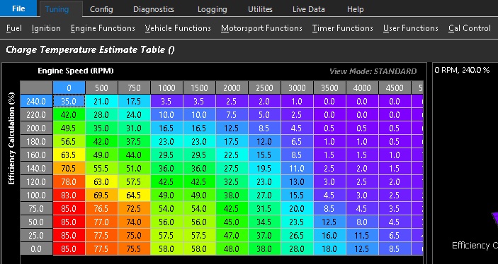
Charge Temperature Estimation
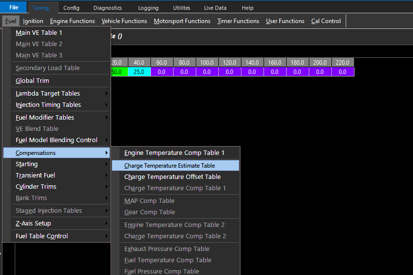
To properly estimate actual “inlet air temperature”, the Emtron will generate a channel called “Charge Temperature”, which is calculated and offset based on a number of variables.
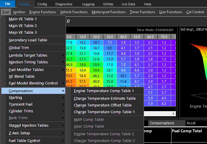
The Charge Temperature Estimation table is available under Tuning -> Fuel -> Compensations -> Charge Temperature Estimation
A value of 100 will set the Charge Temperature as Engine Temperature (commonly water temp), and a value of 0 will set the Charge Temperature as Inlet Air Temperature.
A careful blending of these values will allow the user to properly estimate the charge temperature going into the engine under varying loads to anticipate heat soak scenarios, and eliminate error from the engine model.
** See KV Sample file for an example of of how the Charge Temperature Estimate Table can be used.
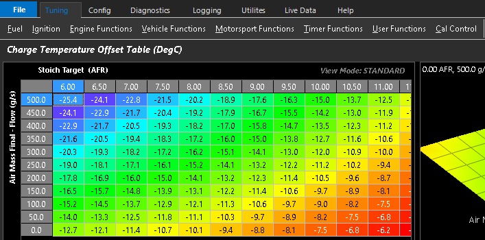
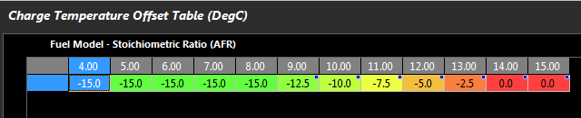
Charge Temperature Offset
The Charge Temperature Runtime can also be “offset” by a table under Tuning -> Fuel -> Compensations -> Charge Temperature Offset
The purpose of this table allow the Charge Temperature runtime to gain greater accuracy based on any other variables the user deems necessary
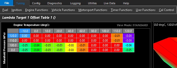
The most common use of this table is to account for charge cooling based on fuel injected in the engine as shown above, where the ECU is using “Stoich Target”, that is a runtime generated by the ECU using the current Stoich value multiplied by the live Lambda Target value (therefore current Air to Fuel Ratio). The fuel type being used for example can vastly affect the actual AFR and subsequently offset the actual Charge Temperature
The Air to Fuel Ratio in this instance is relative to charge cooling, and how this table is being built.
Ignition
Ignition section allows the user to tune multiple tables regarding ignition control
Some noteworthy functions are :
Charge Temperature Comp Table
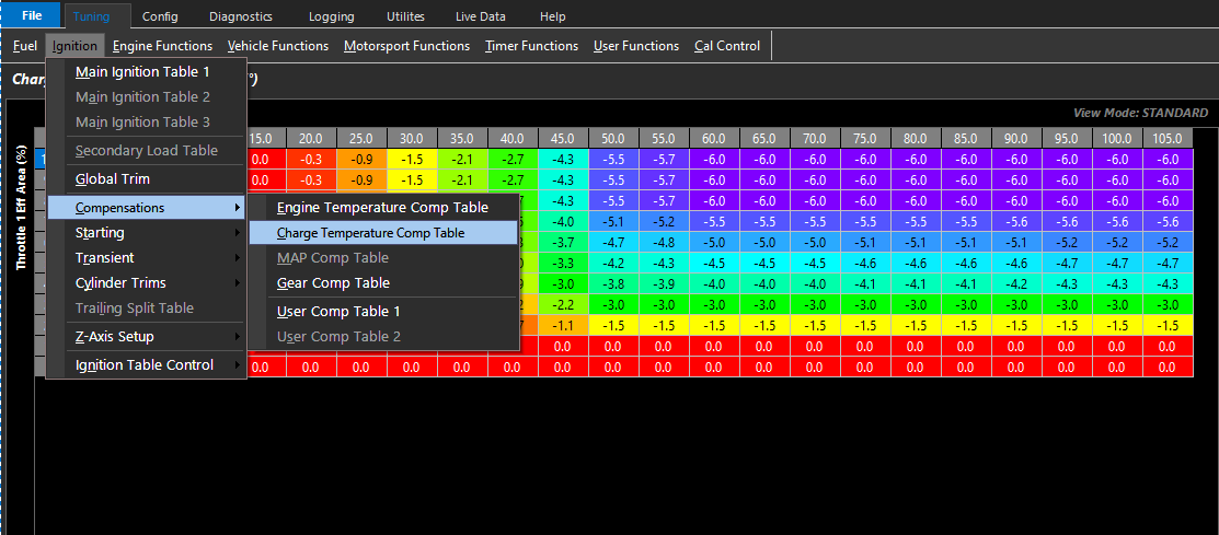
As mentioned in the fuel section, due to some differences in how the Charge Temperature channel is calculated in the Emtron model (particularly how it is offset-ted in the Charge Temperature Offset Table), this table must have special attention as the values for Charge Temperature may not be what the user is “used” to.
** The values may be much lower where ignition compensation must be applied than normal vs compensating using standard Inlet Air Temperature
Ignition Advance/Retard Rate Tables
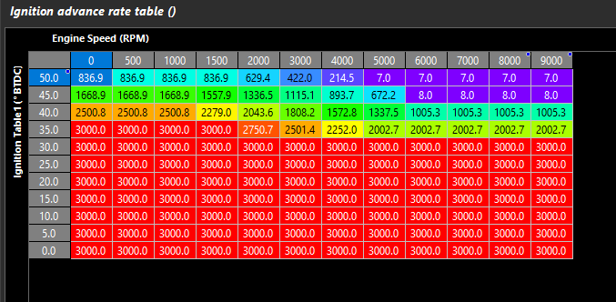
These tables located under Tuning -> Ignition -> Transient are always active
They dictate how quickly the ignition advance can be changed, and a table can be generated to slow/speed up the advance/retard rate.
The values are in degrees/second. Maximum values are 3000 degrees/second.
Engine Functions
Engine Functions section allows the user to tune functions related to “Engine”, such as throttle body, torque, idle speed, drive by wire, etc.
Some noteworthy functions are :
Torque Management
The Torque Management section allows the user to dictate various torque settings.
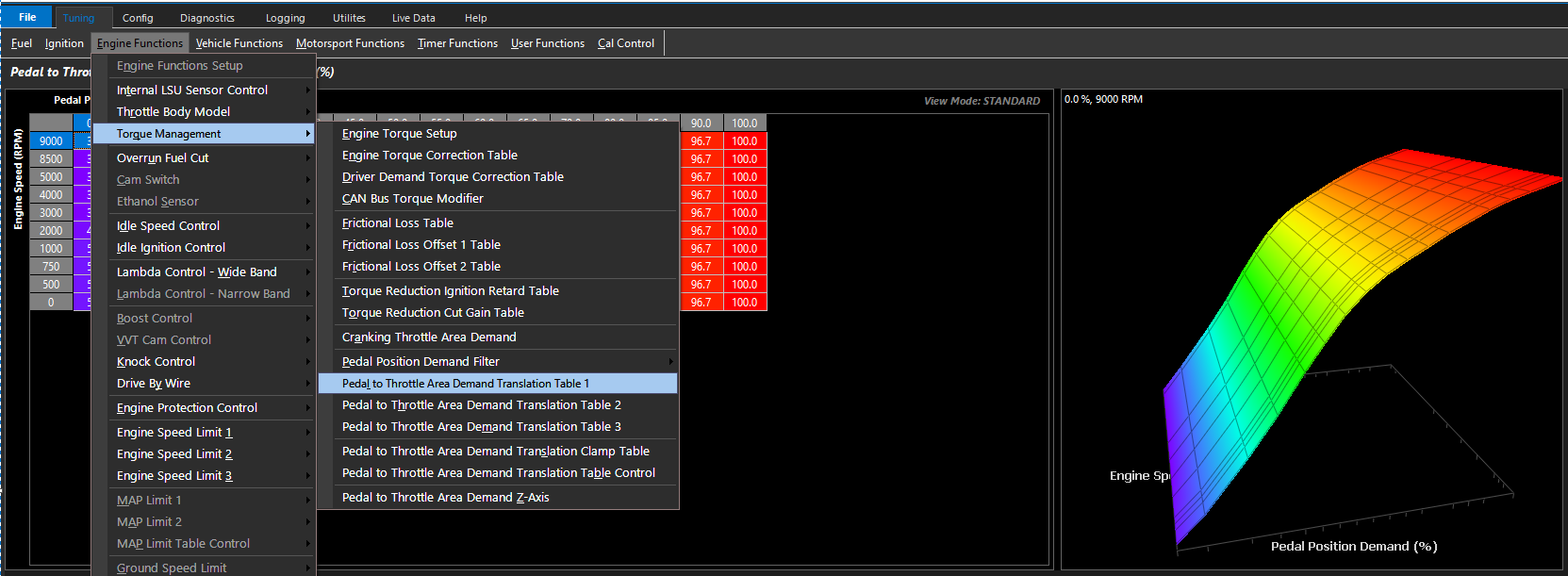
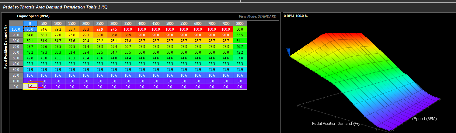
One main difference is if Drive By Wire throttle is used, the targeting structure is based on a Pedal Demand -> Throttle area function.
Please see the Drive By Wire, Throttle Body Model, and Torque Management sections for more help on these sections.
Vehicle Functions
Vehicle Functions section allows the user to tune functions related to “Vehicle”, such as EFI Relay Control, Cooling Fan, Fuel Pumps, Air Con, etc.
Some noteworthy functions are :
Vehicle Dynamics
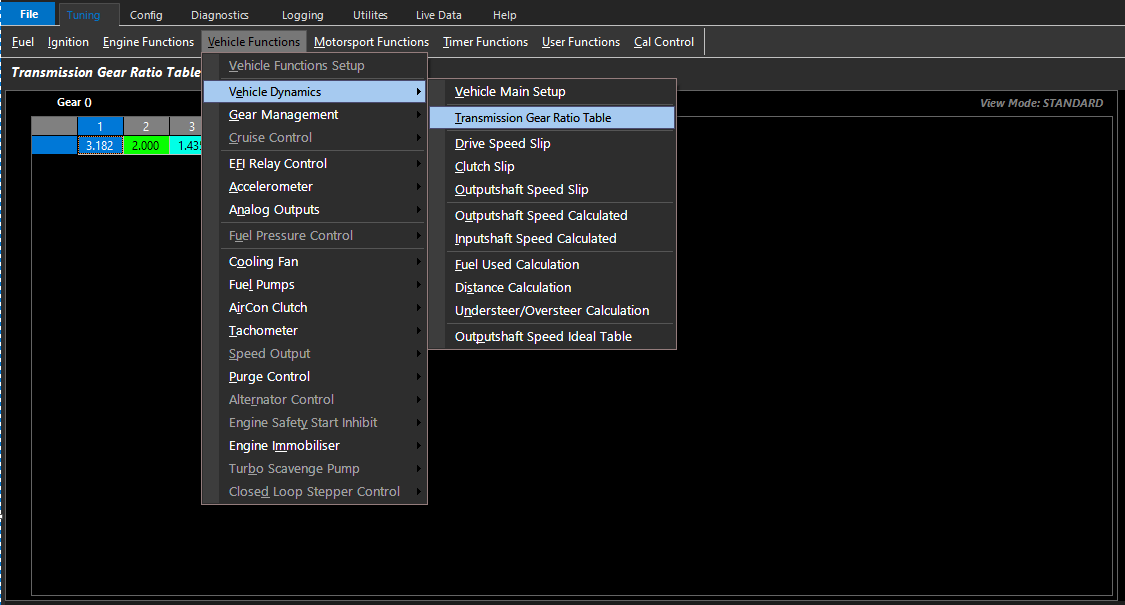
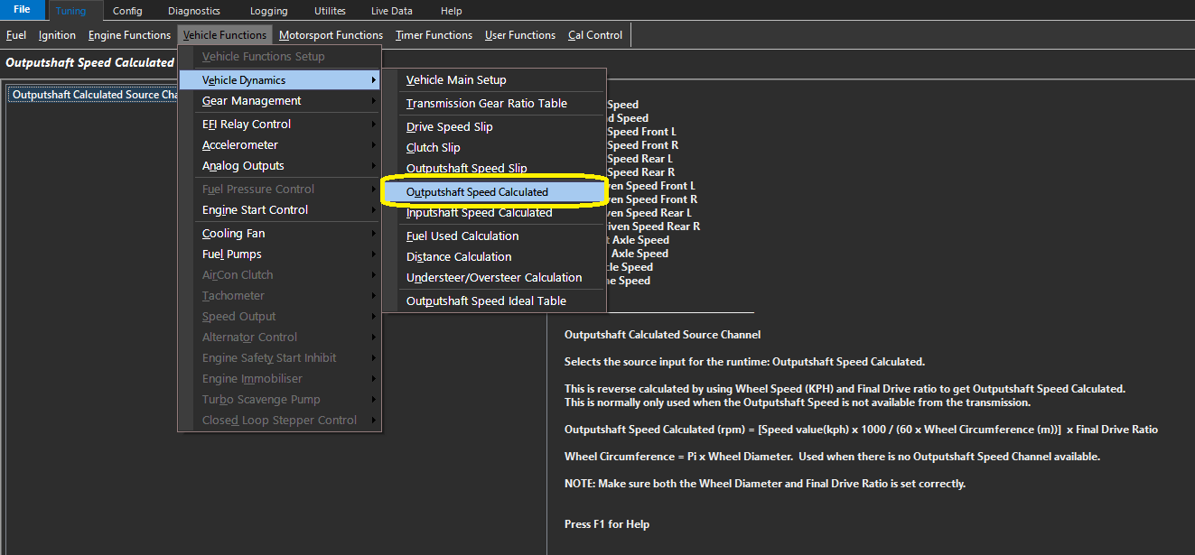
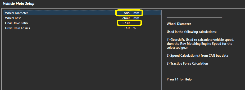
Vehicle Dynamics section allows the user to dictate wheel sizes, gear ratios, slip channels, etc.
For advanced Motorsport Functions to correctly operate, these settings must all be properly configured.
Gear Management
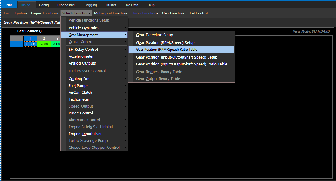
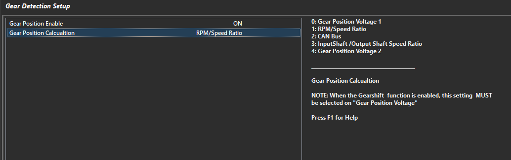
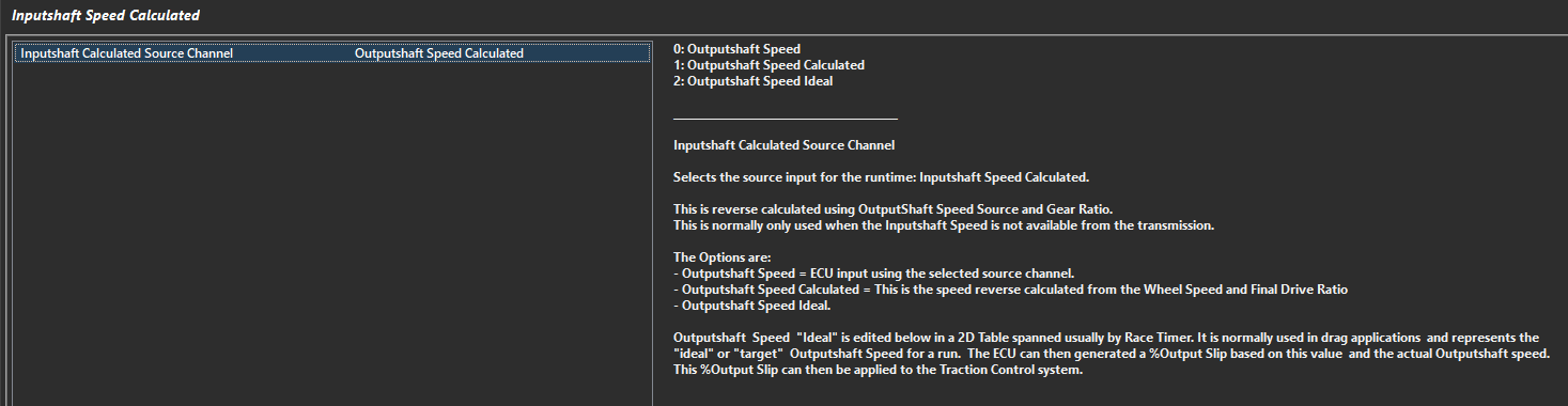
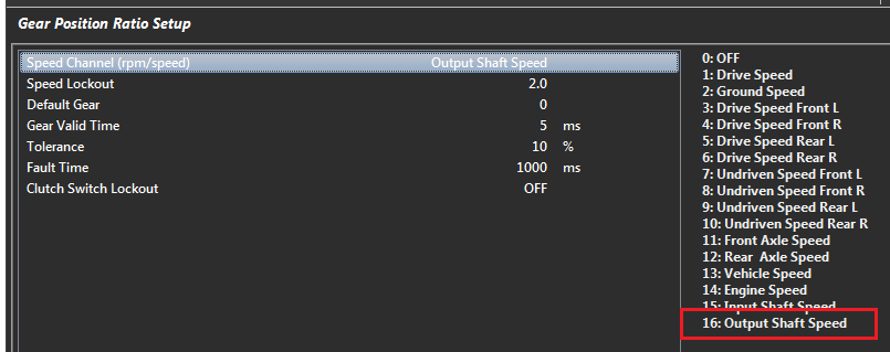
Emtron has multiple methods of Gear Detection. In this section, these detection methods can be configured.
** In order for Motorsport Functions to correctly operate, these settings must all be properly configured.
Motorsport Functions
Motorsport Functions section allows the user to tune functions related to “Motorsport”, such as Anti-Lag, Launch Control, Gearshift Control, Traction Control, etc.
Some noteworthy functions are and more complex functions are listed below simply as a preview of these complex functions :
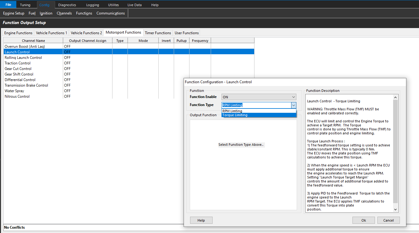
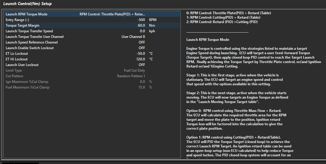
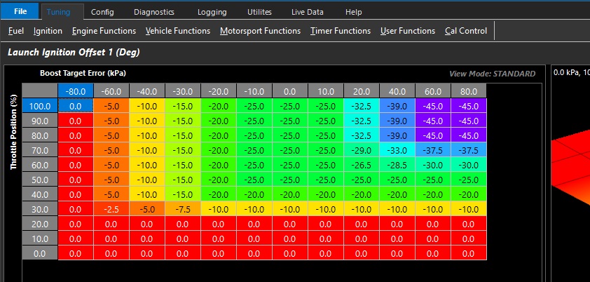
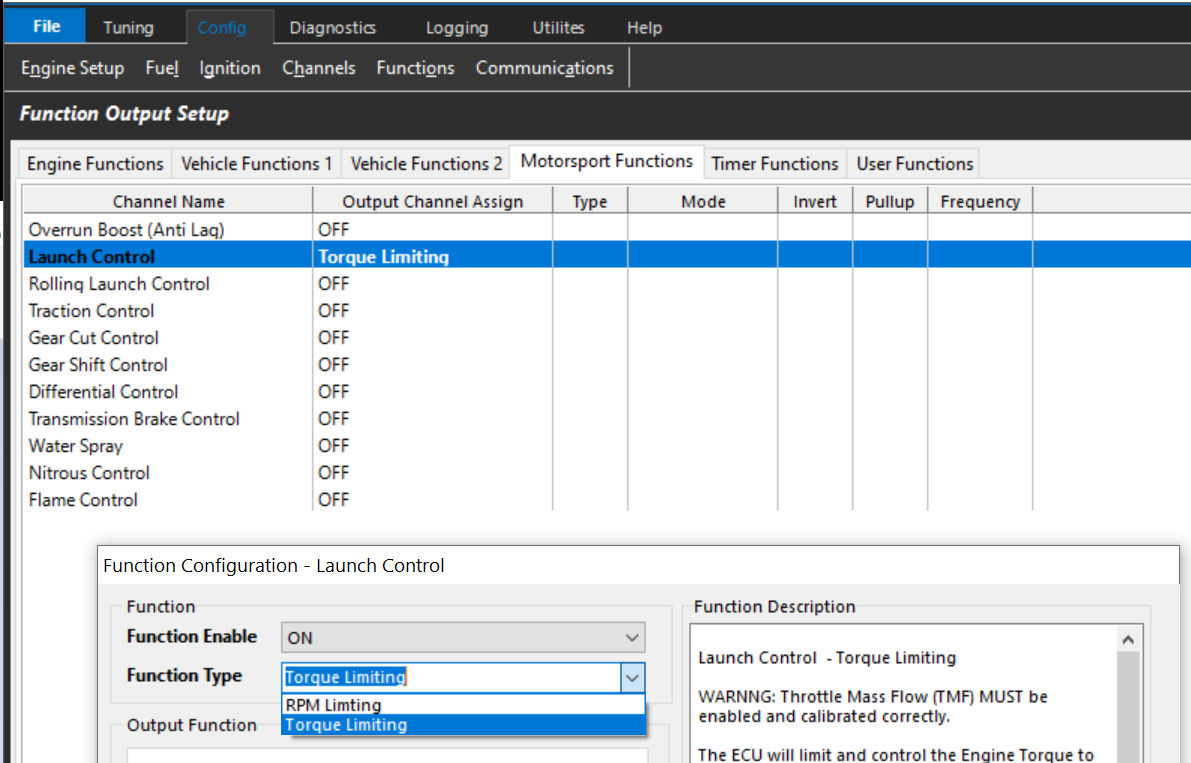
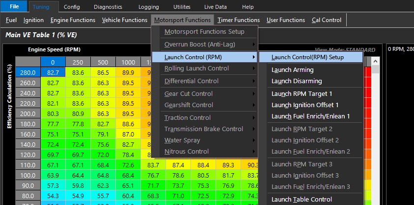
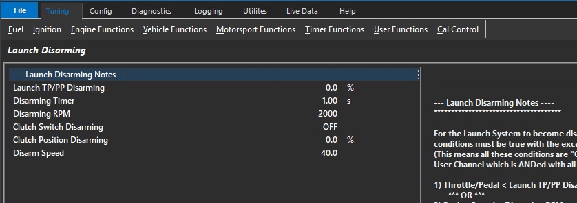
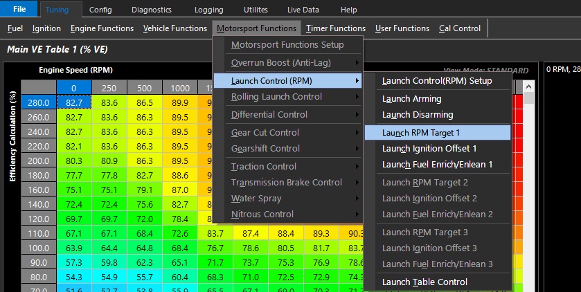
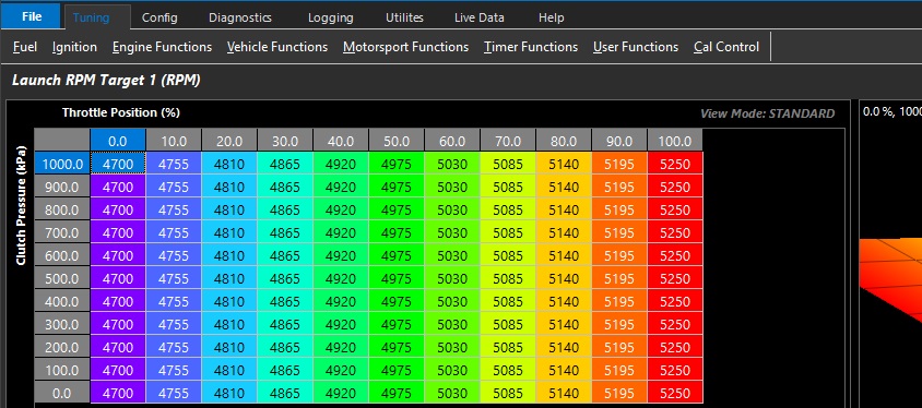
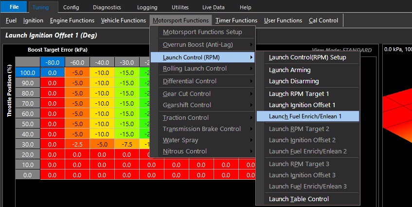
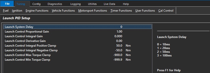
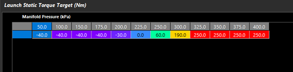
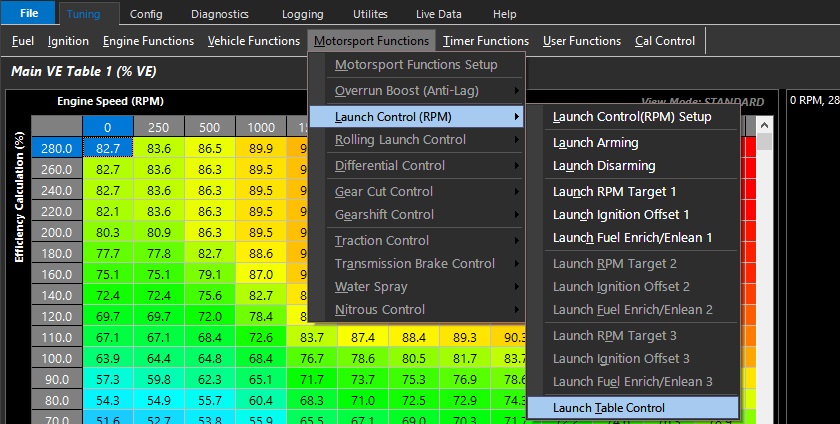
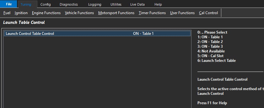
When selecting Torque Limiting Launch Control, multiple types of Torque Limiting Launch are available under the tuning tab
See Launch Control Help section for more details on different Launch Control Programs
Gearshift Control
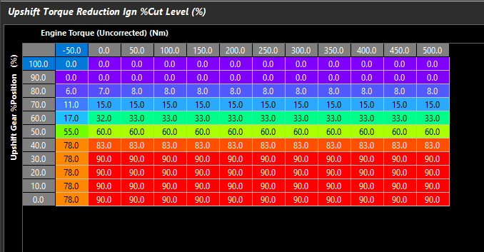
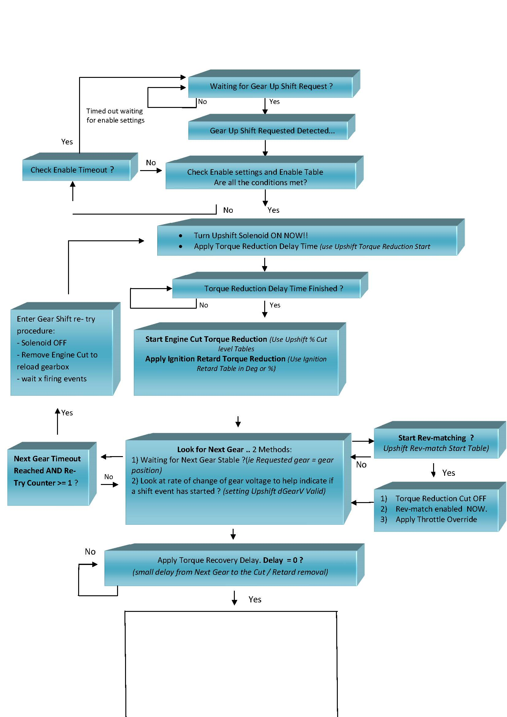
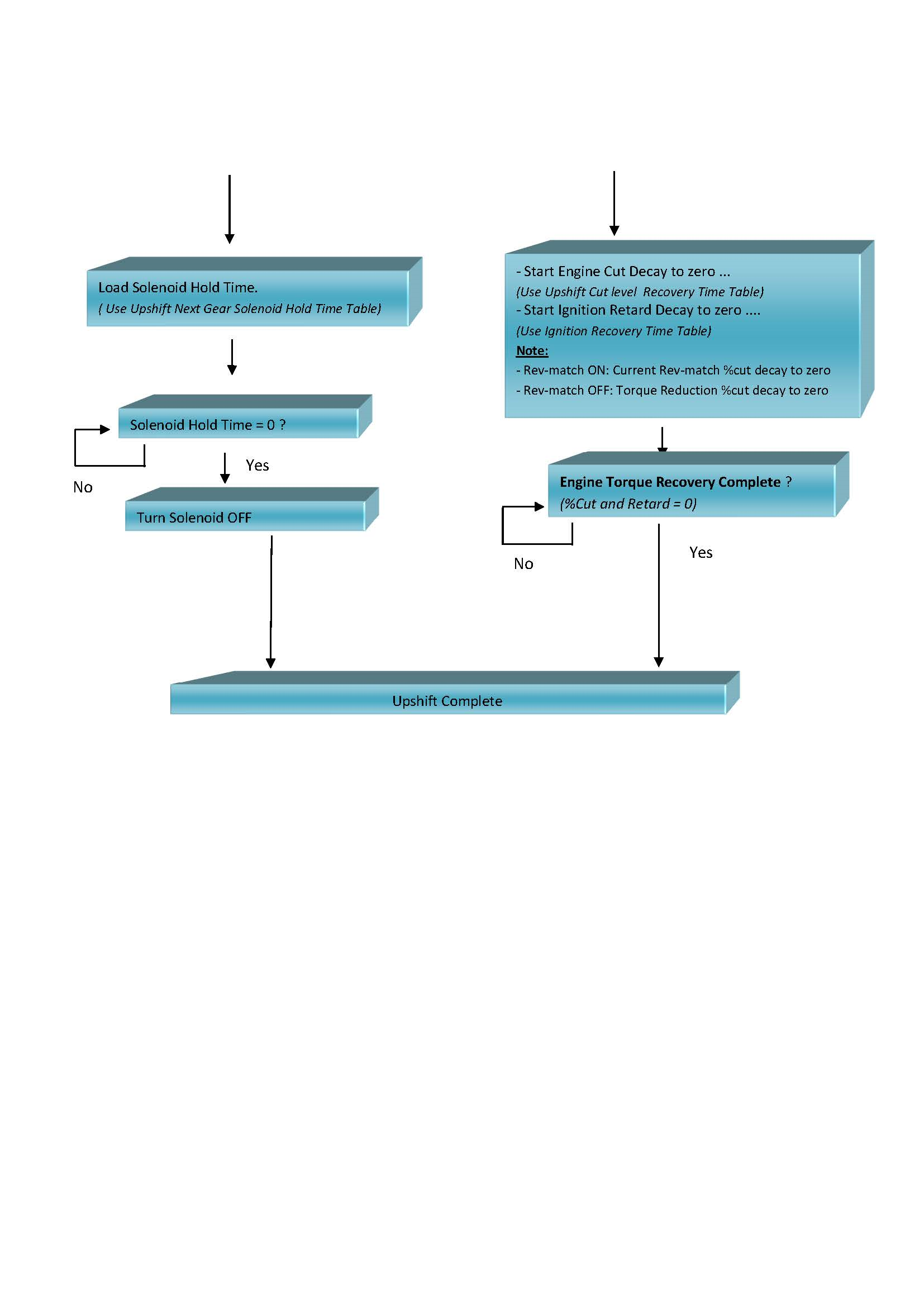
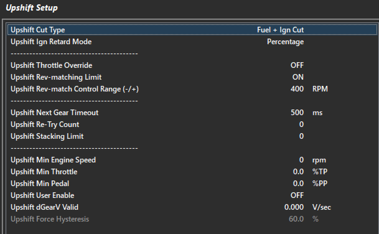
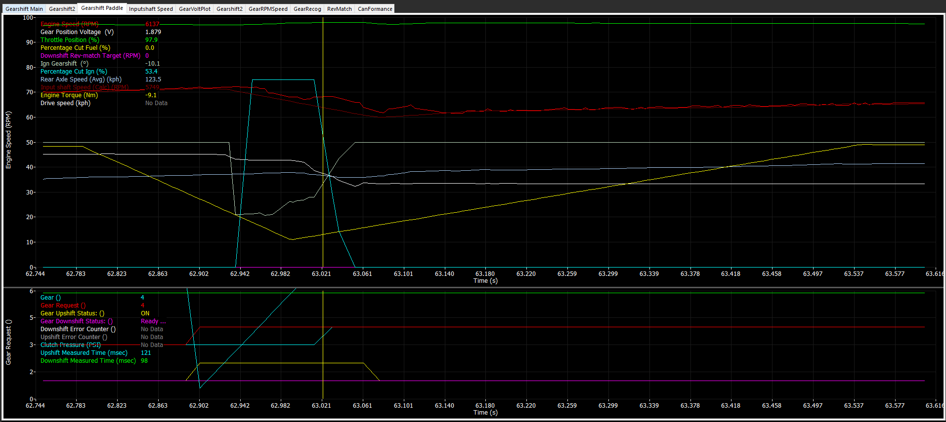
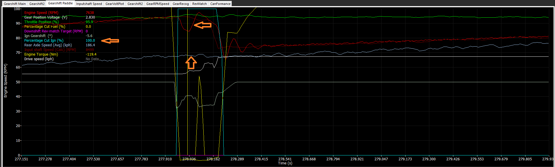
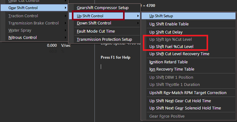
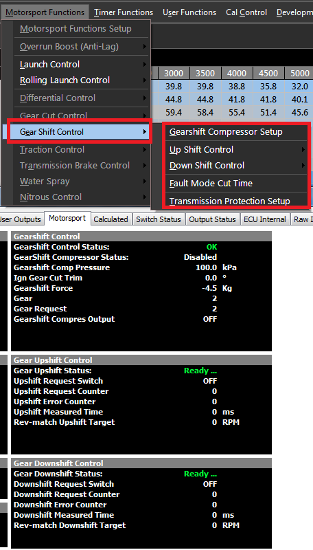
Emtron can control multiple types of Gearshift Control (mechanical gear stick, paddle shift, etc). Once enabled, there are many settings to further refine gearshift functions and very specific and special runtimes available. This is one of the most flexible systems in the ECU.
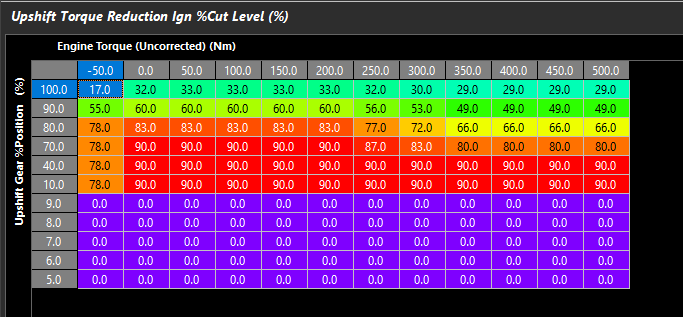
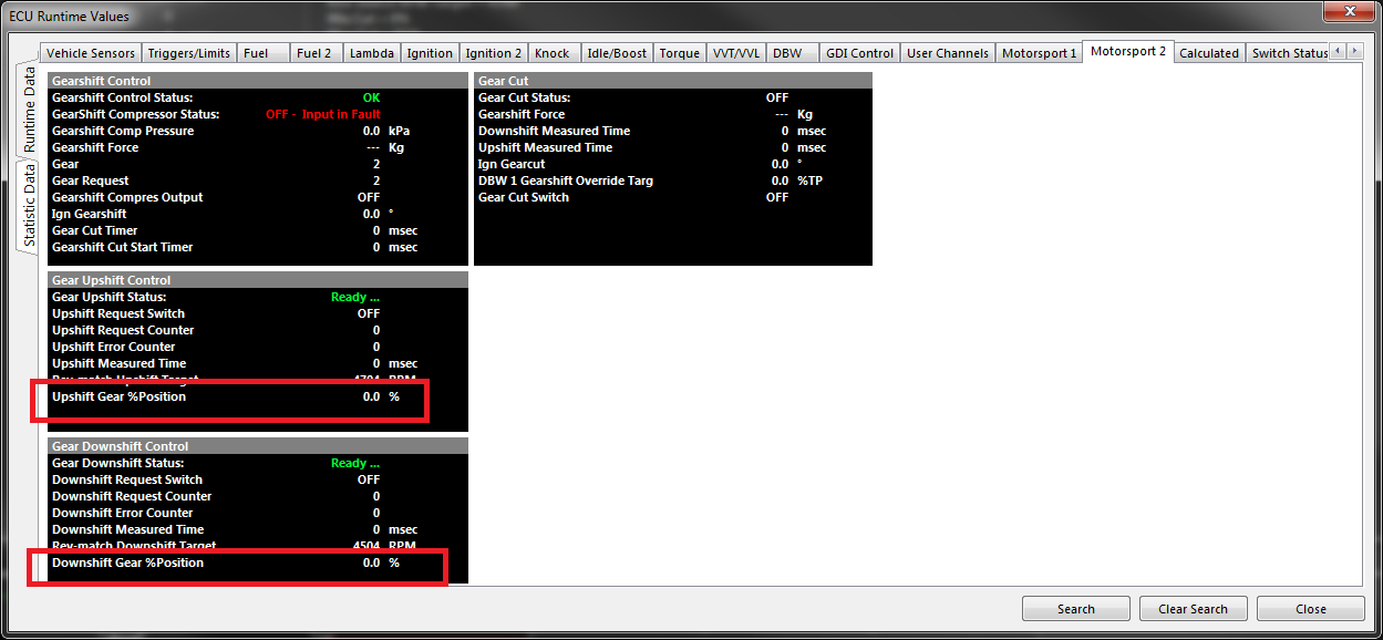
An example of “Upshift Gear %Position” which is the percentage between valid gear (between tolerance voltages if defined in the gear voltage input) being used to limit Ignition cut through a gearshift
Timer Functions
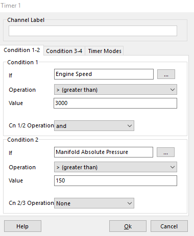
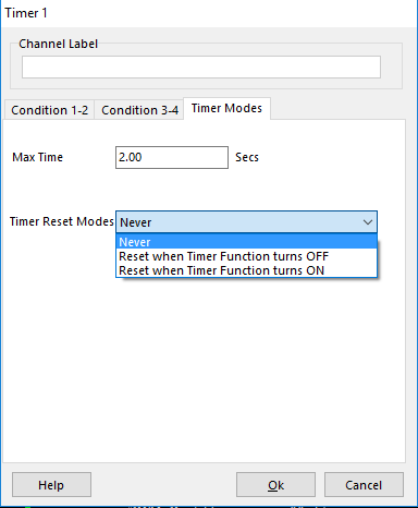
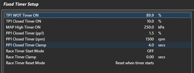
Timer Functions section allows the user to tune functions related to “Timers”. There are 5 user configurable timers, plus multiple standard timers, and a race timer.
These timers generate channels that can be used in the ECU in tables, functions, etc.
User Functions
There are 10 User Functions that allow the user to create universal functions in the ECU.
These functions have multiple conditions to make them active, can be set up to run physical outputs (outputs assigned), or virtual outputs (outputs assigned as “On - No Output”), set as PWM, and even set as variable Frequency.
See Config -> Functions -> User Functions for more details on the flexibility of these functions
** User Function Output status and Duty Cycle runtimes are available to be used furthermore in other locations in the ECU.
Configuration
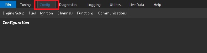
To enter the ECU configuration, click the Config tab at the top. This will give access the the Engine Setup, Fuel, Ignition, Channels, Functions & Communications tabs
The Emtune software has a very systematical approach to configuration. Start on the left side “Engine Setup”, and work your way over from left to right.
Do not skip sections. Following this practice as accurately as possible will ensure tuning process will move smoothly in the future.
WARNING: Incorrect configuration or entry of any setup parameter may result in damage to the ECU electronics or connected hardware.Tuning Tips:
Any increases to the accuracy of the information entered into the configuration of the ECU, will serve to reduce the level of calibration error.
The importance of accurate configuration cannot be overstated when the project is to be Torque Modelled. Take the time to ensure all configuration entries are based on accurate, verified information. For example, if an engine is described as a 6.2 litre engine but the actual displacement is 6162 cc, the actual value of 6162 cc should be entered. Using an assumed or rounded value introduces an error into the Engine Model that must then be accounted for during calibration.
Minimising errors during the configuration stage reduces the calibration error that must be addressed during engine tuning. This applies to all configuration parameters, not just engine displacement. In short, if you put the effort into the configuration, your job will be easier when it comes to tuning.*
Emtune has a very systematical approach to configuration.
Start on the left side “Engine Setup”, and work your way over from left to right.
Do not skip sections. Following this practice as accurately as possible will ensure tuning process will move smoothly in the future.
Improper entry in any part of the setup could be detrimental to the electronics AND the hardware!
Setup each tab from top to bottom. See help file for explanation of each individual function, as well as help text in the respective configuration screens.
**Crank index offset MUST always be checked regardless of trigger pre-configuration.
This setting defines the two engine cycle type supported by the ECU.
4-Stroke – The most common engine type. One complete engine cycle occurs over two crankshaft revolutions (720°).
2-Stroke – One complete engine cycle occurs over one crankshaft revolution (360°).
Rotary engines are regarded as 2 stroke engines
Engine Size
The total engine displacement, entered in cc. Enter the exact displacement; do not round this value.
: Important Note: This setting is critical and must be configured accurately, as engine displacement is used by the ECU in various calculations that form part of the engine model. An incorrect engine displacement can therefore affect the accuracy of multiple calculated parameters, including Air Mass and Engine Torque.
i.e Do not round this setting, use the exact displacment.
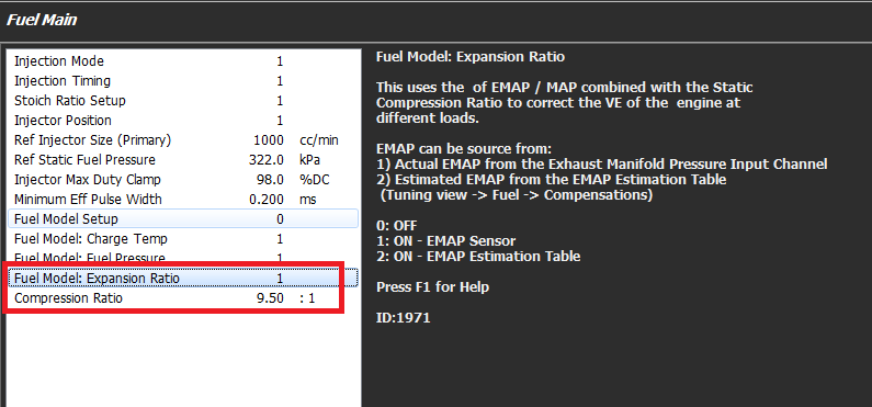
Compression Ratio
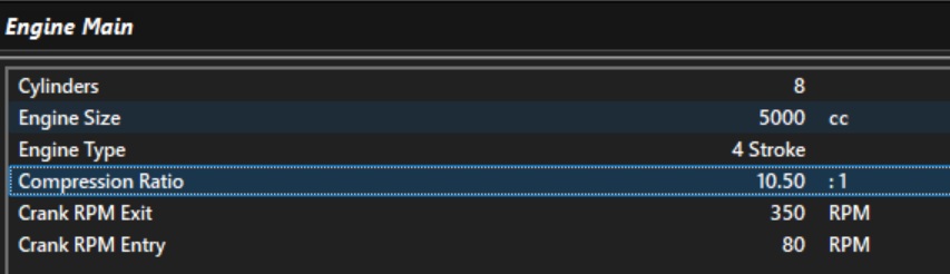
This value is the static compression ratio of the engine. ie: Swept volume over clearance volume.
This setting is used to 2 important calculations:
Used to calcaulte the Clearance Volume which forms part of the Expnansion Ratio calcuation. See Speed Density: VE Expansion Ratio for more infomration
Used by the Engine Torque Model to account for the effect of engine compression on the conversion of combustion energy into torque. See Torque Model for more infomration.
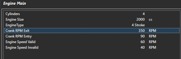
Crank RPM Entry
Used to determine the Engine Speed which is considered as cranking. Various compensations also use this value to determine when to be enabled.
The value entered must be low enough at cranking speeds to ensure the cranking compensations can be enabled.
Crank RPM Exit
Defines the engine speed above which the engine is considered to be running. Various compensations also use this value to determine when they should be enabled.
NOTE: Should you have an engine that is difficult to initially cold start, that is it doesn’t start on first crank, rather on the second or third attempt, then increasing the Crank RPM Exit in some instances can help. This allows the engine to utilize the Crank Comp Table for a little longer allowing for a faster start and quicker handover to a run condition.
Tuning Tip. Any increase in the accuracy of the information entered into the ECU configuration will help reduce calibration error.
The importance of entering the correct engine information cannot be overstated if the project is to be torque modelled. Extra time should be spent to ensure that all configuration entries are accurate.
For example, if an engine is described as a 6.2-litre engine but its actual capacity is 6162 cc, the correct value of 6162 cc should be entered. Any errors introduced during the configuration stage will carry through into the tuning process and contribute to calibration error.
This applies to all configuration entries, not just engine capacity. In short, the more effort you put into getting the configuration correct, the easier and more accurate the tuning process will be.
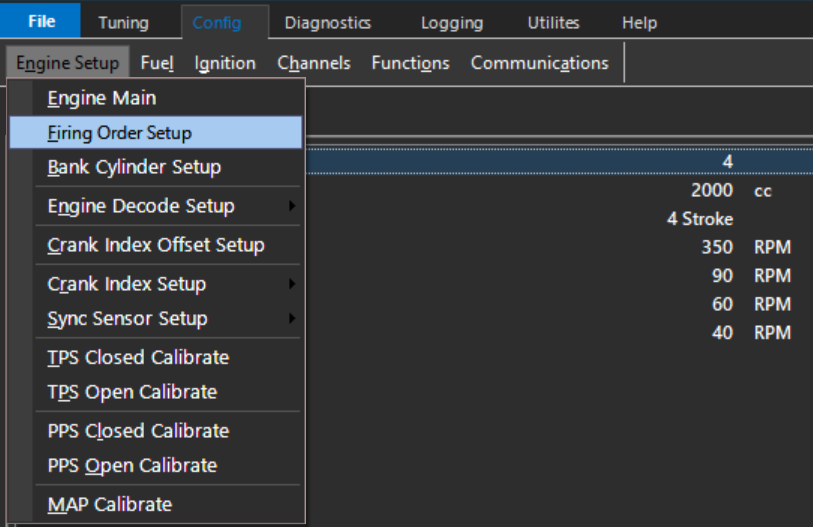
Firing Order Setup
Firing Order Setup
This table is used to define the engine firing order and the base angle for each cylinder.
Most engines are even-fire, meaning that each firing event occurs at an equal crankshaft angle from the previous firing event.
For example, a 4-cylinder, 4-stroke, even-fire engine commonly uses a firing order of 1-3-4-2.
The corresponding base angles are: 0° – 180° – 360° – 540°
For even-fire engines, the Generate Base Angles function can be used to automatically calculate the base angles once the firing order is entered.
For odd-fire engines, the base angles are not equally spaced and must be entered manually, as shown below for a Dodge Viper application.
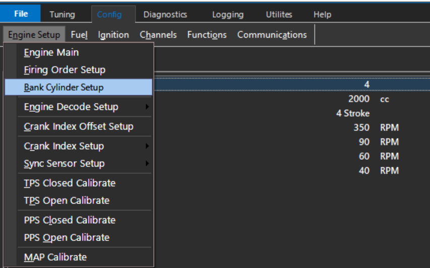
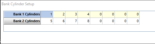
Bank Cylinder Setup
Bank Cylinder Setup
Assigns each cylinder to Bank 1 or Bank 2. This allows the ECU to determine which cylinders the bank-specific fuel or ignition trims are applied to.
The Air Mass Model defines how the ECU calculates the mass of air entering the engine.
Accurate air mass calculation is critical for two primary functions within the ECU:
The calculated air mass is used to determine the required fuel mass to achieve the commanded Lambda Target, before being converted into an injector pulse width using the injector configuration data.
The calculated air mass is used by the Engine Torque Model to estimate engine torque. Accurate air mass calculation is therefore essential to ensure Torque Control and Torque Reduction functions operate correctly.
Important Note: Torque and Air Mass.
The selected Air Mass Model forms the foundation of the ECU Fuel and Torque calculations and should be configured before starting engine tuning.
Just to restate this important point, the ECU calculates engine torque from the Air Mass defined by the Mass Model. This may be derived from Speed Density, TMF, a Mass Air Flow (MAF) Sensor, or another supported air-mass measurement method. The importance of correctly calibrating the selected Air Mass Model cannot be overstated. Accurate air mass modelling is fundamental to achieving accurate engine torque modelling and, consequently, correct operation of the ECU’s Torque Control and Torque Reduction functions.
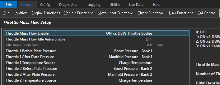
Throttle Torque Reduction can only operate when the Air Mass Model Throttle Mass Flow (TMF) is enabled. TMF is required to accurately calculate the change in air mass across the throttle plate during throttle movements and can therefore provide accurate throttle torque reduction control.
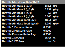
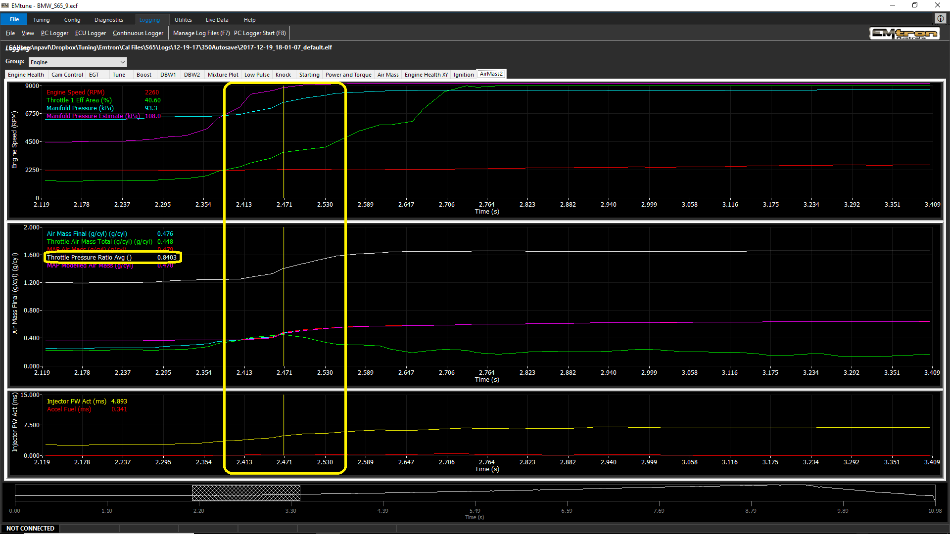
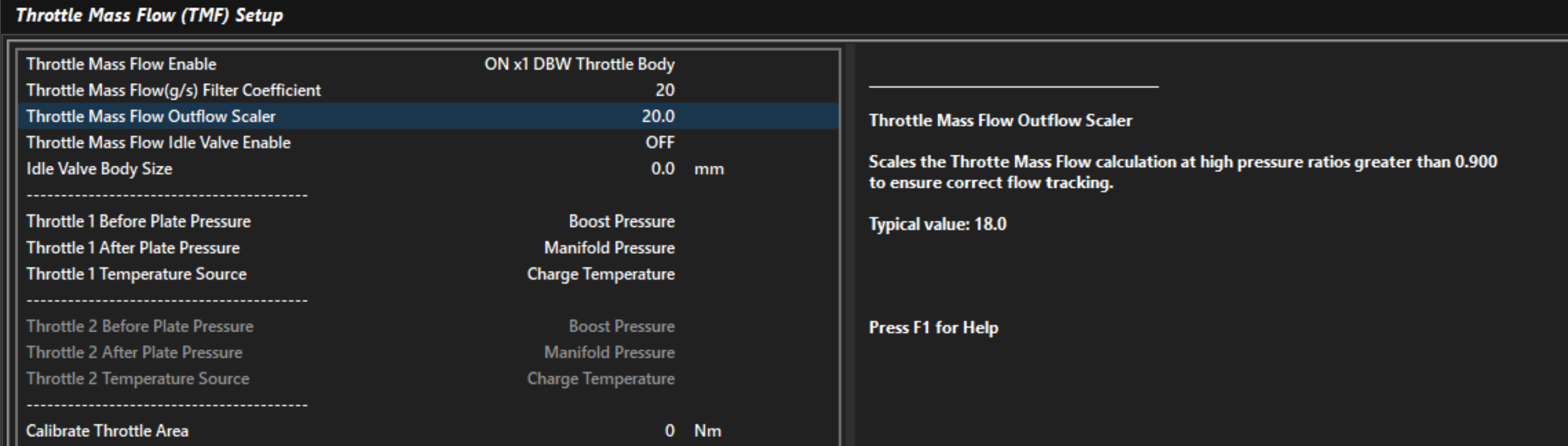
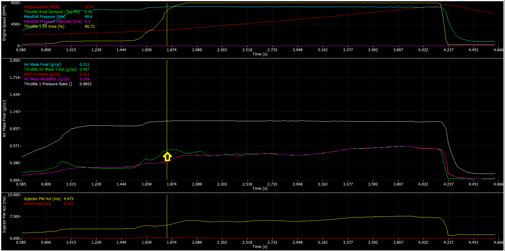
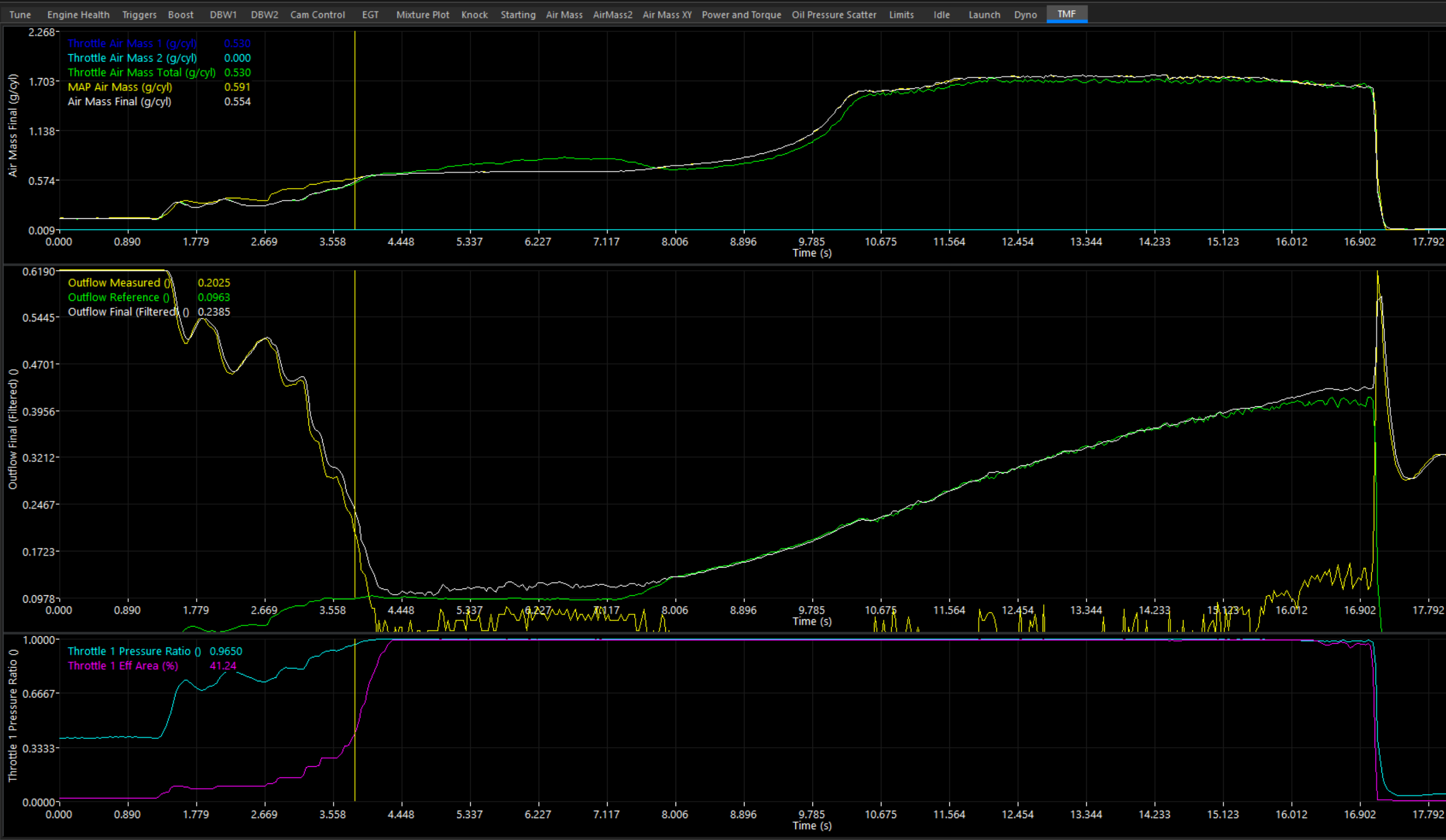
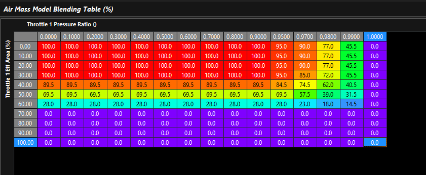
The Throttle Mass Flow (TMF) air mass model cannot be used as a standalone air mass calculation and must always be blended with a secondary air mass model. At throttle pressure ratios above 0.9 (Post-Throttle Pressure / Pre-Throttle Pressure), the pressure differential across the throttle body becomes very small, significantly reducing the sensitivity and resolution of the TMF calculation. This requirement is referenced multiple times throughout the documentation due to its importance when configuring TMF based air mass models.
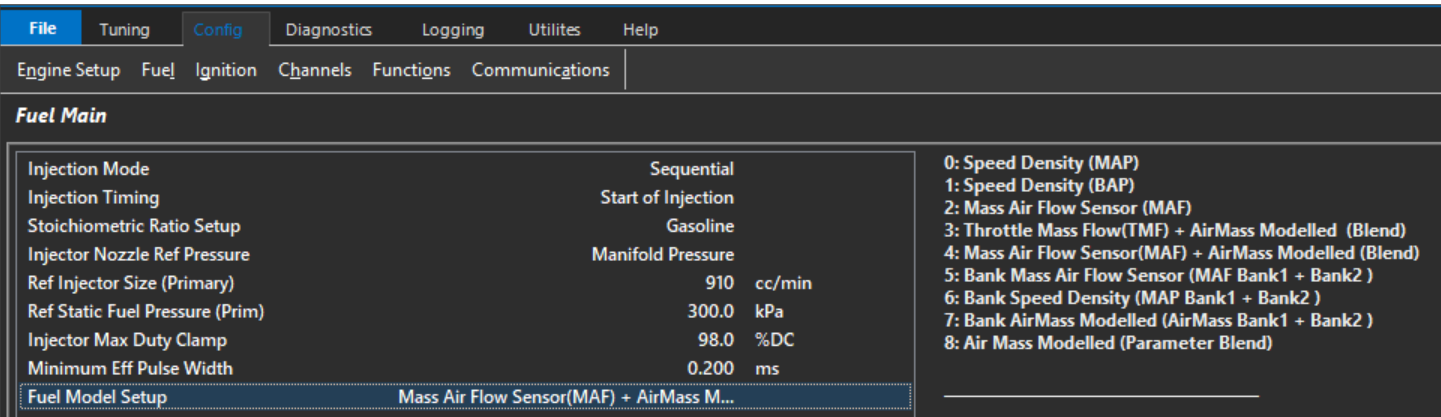
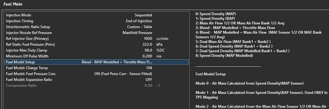
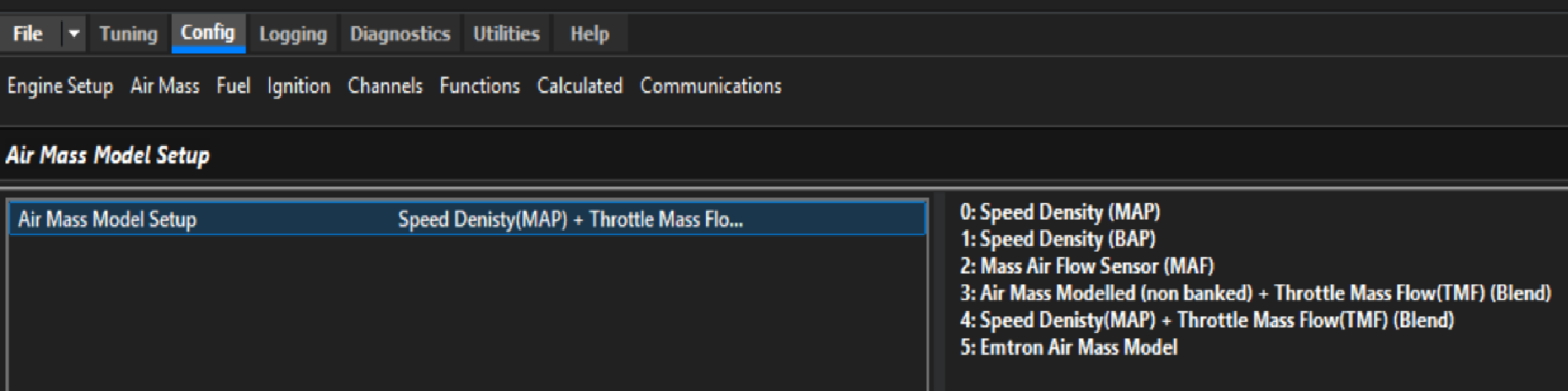
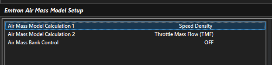
Different engine combinations may benefit from different air mass calculation strategies. Emtron provides several Air Mass Models to suit a wide range of applications. The ECU can calculate engine air mass using the following Air Mass Models:
Setup Options
Value
Air Mass Model
0
Speed Density (MAP)
1
Speed Density (BAP)
2
Mass Air Flow (MAF)
3
Air Mass User 1 + Throttle Mass Flow (TMF) Blend
4
Speed Density (MAP) + Throttle Mass Flow (TMF) Blend
5
Emtron Air Mass Model (Custom)
Air Mass Model Descriptions
Speed Density (MAP)
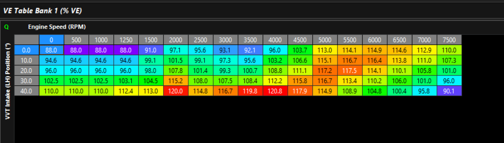
Calculates engine air mass using the Ideal Gas Law based on Manifold Absolute Pressure (MAP), Charge Temperature, Engine Displacement, and Volumetric Efficiency (VE).
Calculates engine air mass using Barometric Absolute Pressure (BAP) instead of manifold pressure. This mode is typically used on naturally aspirated engines operating with individual throttle bodies (ITBs), where manifold pressure is not a reliable indicator of engine load.
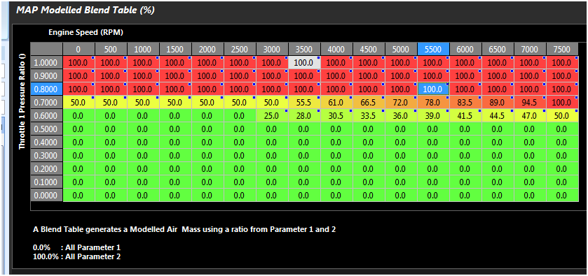
The final engine air mass is generated by blending the calculated Air Mass User 1 value and Throttle Mass Flow (TMF) calculation using the ratio defined by the Air Mass Blend Table.
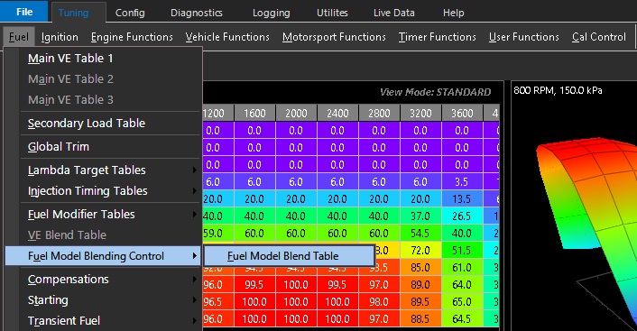
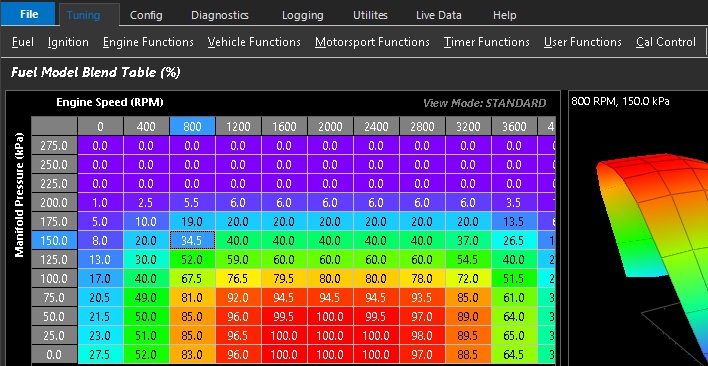
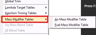
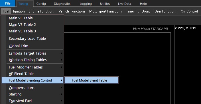
When this mode is enabled the The Air Mass Blend Table becomes active: Tuning -> Fuel -> Air Mass Model Blending Table
Speed Density (MAP) + Throttle Mass Flow (TMF) Blend
The final engine air mass is generated by blending Speed Density (MAP) value and Throttle Mass Flow (TMF) calculation using the ratio defined by the Air Mass Blend Table.
When this mode is enabled the The Air Mass Blend Table becomes active: Tuning -> Fuel -> Air Mass Model Blending Table
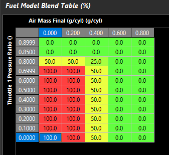
At throttle pressure ratios above approximately 0.9 (Post-Throttle Pressure / Pre-Throttle Pressure), the pressure differential across the throttle body becomes very small, reducing the resolution of the Throttle Mass Flow (TMF) calculation. This is why TMF must always be blended with an alternative air mass calculation method and cannot be used as the sole air mass model for engine operation.
The Air Mass Blend Table should therefore progressively transition from TMF to an alternative air mass calculation method as the throttle pressure ratio approaches 1.0
The Air Mass Blend Table forms part of the engine air mass model and must be finalised before tuning starts.
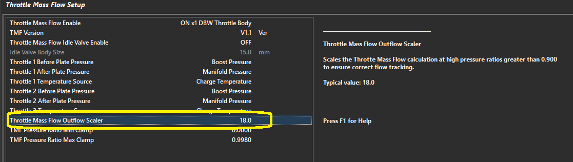
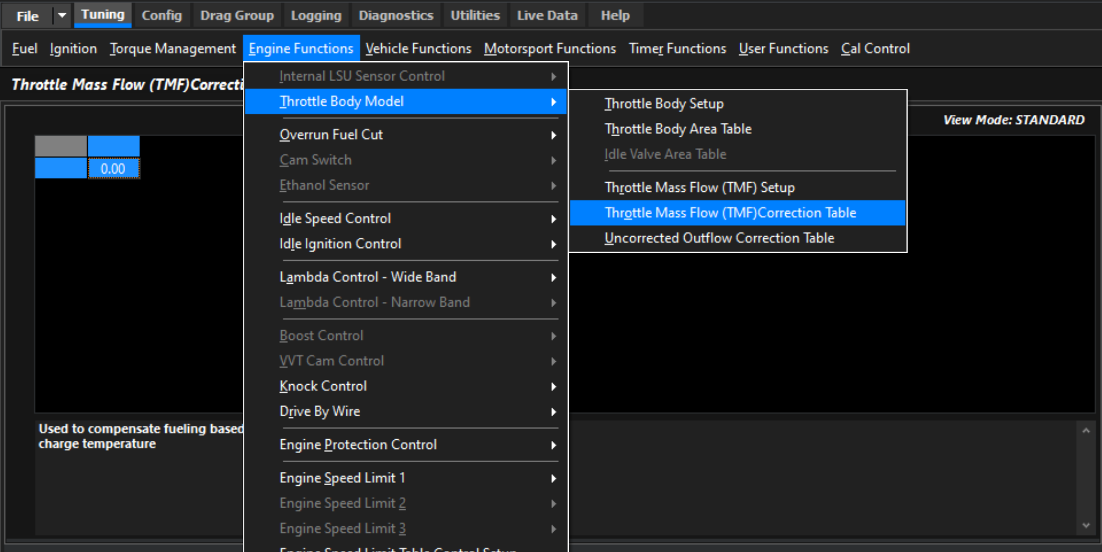
The TMF Correction Table can be used to make small adjustments to the TMF calculation if required. In most applications, little or no correction should be necessary.
Emtron Air Mass Model (Custom)
Uses the custom Emtron air mass model. See here for more information: Emtron air mass
Air Mass Blend Table
When Air Mass Model 3, 4 or 5 is selected, the Air Mass Blend table is enabled.
This table determines the contribution(ratio) of each air mass model used to calculate the final engine air mass.
Intermediate values proportionally blend between the selected air mass models.
This option is only available using the Emtron Air Mass Model. See Emtron Air Mass Model
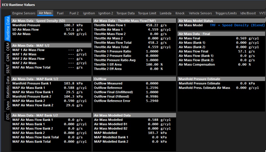
Air Mass Runtimes
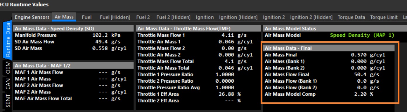
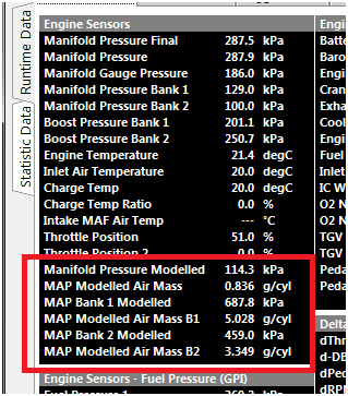
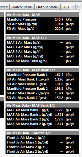
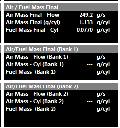
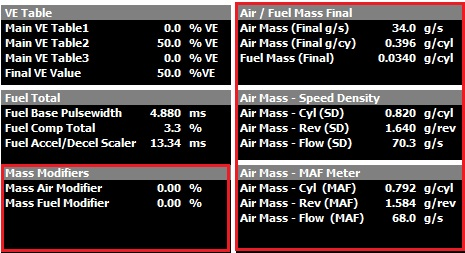
All ECU air mass related runtimes can be viewed from: ECU Runtime -> Air Mass
Note on Units: Air Mass Flow is expressed in units of g/s (grams per second), while Air Mass is expressed in units of g/cyl (grams per cylinder), representing the mass of air trapped in the cylinder during a single engine cycle.
Speed Density (BAP)
Speed Density (BAP Sensor)
Speed Density (BAP) mode is predominantly used in TPS only tuning methods.
This mode uses the same Fuel Model and equations as listed for mode 0 (Speed Density (MAP)), the only difference is the MAP sensor is replaced with the BAP sensor.
Speed Density (MAP)
Overview
The ECU’s primary Air Mass Model is Speed Density (MAP Sensor).. The basis of this calculation is derived using the Ideal Gas Law; PV = nRT
The ECU calculates the injection time for speed density using the following information:
Displacement volume per cylinder (cc).
Intake Manifold Air Pressure - MAP(kPa)
Lambda Target (La)
Stoichiometric Ratio of the Fuel (Stoich)
Injector Flow rate (cc/min)
Charge Temperature (DegC)
Fuel Density (g/ml)
Fuel Pressure (kPa)
Engine VE (%)
Gas Constant - R = 287J/Kg/K for Dry Air.
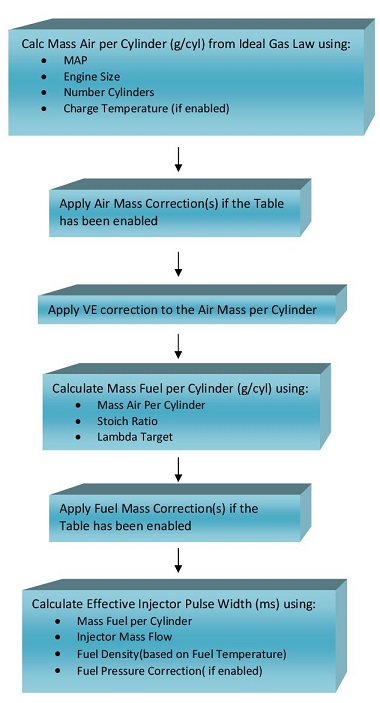
Using these inputs, the ECU calculates the mass of air trapped within each cylinder for every engine cycle. The calculated air mass is then used to determine the required fuel mass to achieve the commanded Lambda Target, before being converted into an injector pulse width.
Important Note
Since the air mass is calculated rather than measured directly, the accuracy of the Speed Density model depends heavily on correct calibration of the Volumetric Efficiency (VE) table(s).
In the predefined Speed Density (MAP) Air Mass Model, the pressure source is fixed to the Manifold Pressure input channel and cannot be changed.
If an alternative pressure source is required, this is only available when using the Emtron Air Mass Model (Mode 5):
Set Air Mass Model = Emtron Air Mass Model
Configure Calculation 1 or Calculation 2 as Speed Density
Configure the desired pressure source from: Config → Air Mass → Speed Density Setup → Speed Density MAP Source
Speed Density Setup
The Speed Density setup parameters are configured from: Config → Air MAss → Speed Density (SD) Setup
The following settings are used to configure the Speed Density Air Mass Model.
VE Table Control
Selects the method used to generate the final Volumetric Efficiency (VE) value used by the Speed Density calculation (Non-Banked Mode).
This setting is only available when the selected Air Mass Model uses Speed Density.
Value
Mode
0
Not Available
1
Table 1
2
Table 2
3
Not Available
4
Cal Slot
5
Not Available
6
Z-Axis
7
VE Blend (VE Table 1 / VE Table 2)
Table 1: Uses VE Table 1 exclusively for all engine operating conditions.
Table 2: Uses VE Table 2 exclusively for all engine operating conditions.
Cal Slot: Allows the active VE table to be switched dynamically in real time using the Calibration (Cal) Slot Table function. See : Tuning → Cal Control
Z-Axis: Enables a user configurable third operating axis to blend or switch between VE Table 1 and VE Table 2. The Z-axis can use any available ECU runtime making it suitable for applications such as:
Variable camshaft systems (VTEC/VVL)
Alternate fuel calibrations
VE Blend: Uses the VE Blend Table to generate the final VE value by blending between VE Table 1 and VE Table 2.
0.0% = All VE Table 1
50.0% = Equal blend of VE Table 1 and VE Table 2
100.0% = All VE Table 2
Speed Density Charge Temperature Enable
When enabled, the ECU includes Charge Temperature in the Speed Density air mass calculation. The ECU automatically corrects the calculated air mass based on Charge Temperature Estimate using the Ideal Gas Law. For this reason, the Charge Temperature Compensation Tables should initially be configured to zero (not used).
When disabled, the Speed Density model assumes a fixed charge temperature of 20°C and the Charge Temperature Compensation Tables are therefore required to provide the necessary fuel compensation.
Recommended Setting: ON
VE Expansion Ratio
The VE Expansion Ratio feature uses the relationship between:
Exhaust Manifold Pressure (EMAP)
Manifold Absolute Pressure (MAP)
Engine Static Compression Ratio
to correct the effective volumetric efficiency of the engine as exhaust backpressure changes.
NOTE: VE Expansion Ratio correction operates only when the Air Mass Model is configured for Speed Density mode as this is a VE correction.
This is particularly beneficial on turbocharged engines operating at high boost pressures where increasing exhaust backpressure can significantly influence cylinder filling efficiency.
Selects the pressure source used by the Speed Density calculation. This setting is ONLY available when the selected Air Mass Model is Emtron Air Mass Model.
For all predefined Air Mass Models this setting defaults to the Manifold Pressure input and cannot be modified.
The following pressure sources are available:
Value
Pressure Source
0
Off
1
Barometric Pressure
2
Manifold Pressure
3
Manifold Pressure - Bank 1
4
Manifold Pressure - Bank 2
5
Manifold Pressure - Bank 1 / 2 Average
6
Boost Pressure
7
Boost Pressure - Bank 1
8
Boost Pressure - Bank 2
9
Boost Pressure - Bank 1 / 2 Average
10
MAP Estimate
11
User Pressure 1
12
User Pressure 2
13
User Pressure 3
14
User Pressure 4
Speed Density MAP Bank 1 and Bank 2 Source.
Selects the pressure source used for each individual bank Speed Density calculation.
This setting is only available when:
The selected Air Mass Model is Emtron Air Mass Model
Air Mass Bank Control is enabled
The same pressure source options described in Speed Density MAP Source are available for both Bank 1 and Bank 2 calculations.
Example:
MAP = 252kPa
Charge Temperature = 30.7 DegC
Volume Per Cylinder = 666.6
Stoich Ratio = 9.9
Lambda Target = 0.785
Engine VE = 96.6 %
Fuel Mass (g) = 0.2395
In this basic example, if the cylinder achieves 96.6% volumetric efficiency, then 0.2395 grams of fuel is required to achieve a Lambda Target of 0.785.
The VE Table(s) define the volumetric efficiency of the engine at varying engine speeds and loads and represent the True VE of the engine. A typical table is shown in Figure 1 for a turbo charged engine.
Fuel VE Table
Figure 1
Also, the Stoichiometric Ratio will vary with Fuel Type. A Single Zone if the fuel type is fixed (Figure 2) can be used or a Table allowing the ECU to constantly correct for varying alcohol content. See Figure 3.
Stoich Ratio Setup (single) Figure 2
Stoich Ratio Setup (table) Figure 3
Notes on Effective Pusle width
Once the required Fuel Mass has been determined from the calculated Air Mass, the ECU calculates the effective injector pulse width using:
Injector Size
Fuel Density. Fuel density is used to convert between fuel mass and fuel volume and can be a function of both Fuel Temperature and Alcohol Content. A typical Fuel Density table is shown below in Figure 4
Fuel Pressure Correction. Fuel Pressure Correction is based on the injector flow relationship described by Bernoulli’s Equation and allows the effective injector flow rate to be adjusted as the differential pressure across the injector changes.
Note: Fuel Pressure Correction is only applied when enabled using the Config -> Fuel -> Fuel Main → Fuel Pressure Corr. setting.
Fuel Density Table Figure 4
Mass Air Flow Sensor (MAF)
Overview
The Air Flow Sensor(s) provides a measured Air Mass Flow in g/s. The ECU then converts this into air mass per cylinder (g/cyl) giving actual Air Mass into the Engine.
The following MAF input channels can be used:
Mass Air Flow Sensor(s) 1 and 2
Mass Air Flow Bank Sensor(s) 1 and 2 can be used
The ECU will search which channel(s) are enabled and use those inputs. “Mass Air Flow Sensor” takes priority over “Mass Air Flow Bank Sensor”. For example if both
Mass Air Flow Sensor1 and Mass Air Flow Sensor2 input channels are configured the ECU will automatically use both inputs.
MAF systems are more flexible in their ability to compensate for engine changes(like altitude and IAT) since they actually measure airflow instead of calculating it like the Speed Density Fuel Model. It also greatly reduces the tune time as you no longer need to adjust the fueling based on the VE of the Engine… its automatically accounted for by the MAF sensor.
However they also have limitations around restriction and sensor range on high power engines.
Once the Mass Air has been measured, if the MAF requires further scaling this can be done using a 3D Table. In the real world “small” corrections will need to be applied. This can be done using the Secondary Load Table which will allow a +/- percentage correction to be applied.
A Typical example is shown in below. Table Control should be used to put the Secondary Load Table into this “special” mode shown below
Secondary Load Table used for MAF Sensor
Table Control for Secondary Load Table
Once the Air Mass has been determined, the Stoichiometric Ratio and Lambda Target are used to generate a Fuel Mass (g). The Stoichiometric Ratio will vary with Fuel Type. A Single Zone if the fuel type is fixed can be used or a Table allowing the ECU to constantly correct for varying alcohol content.
Once the Fuel Mass is determined, the Effective Injector Pulse Width can be calculated using:
Injector Size
Fuel Density. Fuel Density can be a function of both Fuel Temperate and Alcohol Content.
Fuel Pressure Correction. The Fuel Pressure Correction is a Fluid Dynamics equation. It allows the injector flow rate to be adjusted as the differential pressure across the injector changes. NOTE: This correction MUST be enabled using the “Fuel Model : Fuel Pressure” setting
Flow Chart Overview for Mass Air Flow Sensor Fuel Model:
Throttle Mass Flow Setup
Overview
Throttle Mass Flow (TMF) as the name indicates, is the rate at which air mass is flowing through a throttle body in units of grams/second (g/s). Using the throttle body size, throttle area, temperature, pre and post throttle pressures,the ECU can very accurately calculate air flow through the throttle body and therefore into the engine; this is known as the TMF Calculation. Other sensors that also generate air mass flow (g/s) data are Manifold Pressure and MAF sensors. The TMF Calculation is just another method of determining air mass flow and has benefits over MAP and MAF as discussed further down.
The image below illustrates the basic elements required to calculate TMF.
Getting into more detail, the flow through a throttle body is governed by three physical elements, Conversation of mass, Newtons second law of motion for fluids and Conservation of energy. By combining these elements the ECU can model the flow of fluid through the throttle body accounting for throttle plate thickness and throttle shaft size. By then including real-time data such as the pressure ratio across the throttle plate and the instantaneous throttle area, the ECU can precisely calculate the mass flow rate through a throttle body.
Although these calculation are complex, the TMF setup process for the user is kept as simple as possible with the following inputs and setup required:
Sensor Inputs required
Pressure Before the throttle Plate
Pressure After the throttle Plate
Temperature
Setting required
Throttle Body Size
Throttle Area to Servo Position Correlation Table (Throttle Body Area Table)
The TMF calculation can be summarised by the following equation:
Throttle Mass Flow (g/s) = ( Pafter / Pbefore) x Throttle Area x Modelled throttle body fluid dynamics equation
Settings
Config-> Air Mass -> Throttle Mass Flow (TMF) Setup
Throttle Mass Flow Enable
Allows the TMF function to be enabled. At this point the ECU is only calculating air mass flow into the engine. Once setup other functions like the Launch and Idle Speed Control can be configured to use the TMF calculated air mass data.
Select which type of throttle system you have:
1x DBW Throttle
2x DBW Throttle
1x Cable Throttle
Throttle Body Size
The Throttle Body inside diameter in millimeters.
Throttle Body Size Scaler
Allows the Throttle Body diameter to be scaled to correct for any system calibration errors. So 60.0 mm diamter with 2.5% scaler gives a throttle diamter of 61.5mm
Default Value = 0.0%
Throttle Mass Flow Filter Mode
This setting controls the Filtering of the Outflow function, a critical part of the TMF Calculation.
Select the Emtron Default to use the Emtron pre-calibrated filter table. Alternativity, for advanced users these default values can be edited using the Custom Table option.
See Tuning -> Air Mass -> Throttle Mass Flow (TMF) User Filter Table
Throttle Mass Idle Valve Enable
Enables the Idle Valve Area to be accounted for in the TMF calculation; the Throttle Body Area AND Idle Valve Area are used to give a Total Area.
Normally only required on a Cable Throttle when an external Idle Air Bleed is used.
Throttle Before Plate Pressure
Pressure source before throttle plate
Commonly Boost Pressure
Also referred to as Charge Pressure
Normally aspirated vehicles can use Barometric Pressure as Pre Throttle pressure source
Throttle After Plate Pressure
Pressure source after throttle plate
Commonly Manifold Pressure
Throttle Temperature Source
The Air temperature input used in the TMF Calculation
Throttle Body Area
Gives the direct relationship between Throttle Area and Servo Position.
See Tuning -> Air Mass -> Throttle Body Model -> Throttle Body Area Table
Throttle Mass Flow Runtimes
The following TMF calculated runtimes are generated. See the Runtime menu (F3) Engine Data Calculated tab.
Throttle Air Flow is expressed in units of g/s (grams per second), while Throttle Air Mass is expressed in units of g/cyl (grams per cylinder), representing the mass of air trapped in the cylinder during a single engine cycle.
Throttle Pressure Ratio is the ratio of Pre Throttle Pressure sensing vs Post Throttle pressure sensing (Boost Pressure vs MAP Pressure most commonly)
Throttle Eff Area is the calculated Throttle Area using the Servo Position and the Throttle Body Area lookup table.
All these runtimes can be utilized within other functions.
Functions that can utilize the TMF Calculation
The following functions can use the air mass data generated from the TMF calculation:
Fuel Model
Option 3: Blend - MAP Modelled + Throttle Mass Flow. TMF Fuel Model calculations can offer advantages when the throttle pressure ratio is low (partial throttle) and respond much faster in transient conditions.
For more information see the Fuel Model section.
Idle Speed Control
Option 6: DBW 1 TMF
Option 7: DBW 1+2 TMF
This allows the Idle Speed control to target Mass Flow Rate of g/s. The Throttle Mass Flow (TMF) idle speed control function delivers extremely accurate and rapid idle calculation based on actual engine’s airflow requirements. See TMF Idle Speed Control section for more information
Launch Control
Option 2: Torque Limiting.
The TMF is used to control throttle plate position to achieve a target torque and target launch engine speed.
Tuning TMF
Once TMF is appropriate set up, it can make mapping the engine when it is in use very fast. Using TMF wherever possible is strongly advised by Emtron, especially depending on what kind of dynamometer being used, test conditions, and more – often part throttle and proper transient setup is often forgiven due to time constraints.
Version 1.0
Due to strictly calculating airflow via pressure ratio, the calculation will become invalid at a near equal pressure ratio through the throttle.
Gradually accelerate the engine under load and increase to increase the throttle area demand/effective area.
** Final air mass calculation which can be affected by engine speed (and more) can affect the optimal blend point. This is why most default configurations for the Fuel Model Blend Table include Air Mass Final runtimes.
In this particular case the TMF signal at around 0.830 throttle pressure ratio is being unusable.
At this same moment, the Air Mass Modelled/blended calculation is stable and can be blended in.
And/or TMF Out-flowing can generate correct TMF values.
TMF Outflowing calculates TMF airflow when pressure ratio cannot.
Improper “Outflow Scaler” setting. Adjust Throttle Mass Flow Outflow Scaler to correct
Throttle Mass Flow Air Flow values can only be compared to validated/tuned air flow values (tuned) such as MAP Air Mass or MAF Air Mass.
TMF Correction Table
This correction table essentially exists to help remove an error remaining in the system across a wide variety of load & rpm conditions.
Demonstrating error in TMF Calculation that needs to be corrected in TMF Correction Table
Tuning the Throttle Body Area Table
The Throttle Body Area table tells the ECU how much actual throttle area is effective at different throttle positions. This is key to the ECUs further Torque Managing functions, as accurate air mass measurement and actual engine torque go hand in hand.
For torque management, Throttle Area Demand can be manipulated which will be directly proportional to air mass when this is configured correctly
Tuning -> Engine Functions -> Throttle Body Model -> Throttle Body Area Table
This 2D table is all that is needed to appropriately map the given throttle area vs throttle position. As mentioned previously, this allows for extremely fast and accurate mapping of the engine when TMF is active.
It is important to understand that the Pedal Demand and other targeting of throttle area will target the "unit location" in this table, which will then correspond to the DBW Servo Position.
This means, there could be little relationship between Throttle Area Demand and actual DBW Servo Position on fully tuned setups.
Blend tables must be configured completely before tuning
There are multiple ways to calibrate the appropriate throttle area.
Method 1 – Torque verification
With calculated torque channels configured and functional, tuning the Engine Torque (TMF) channels to match the standard Engine Torque channels will allow full mapping of the Throttle Area table. See Torque Management Tuning
Method 2 – Matching other forms of Air Mass measurement
If the application is using a calibrated MAF sensor. Then the throttle area % can be adjusted and matched to TMF air mass VS MAF air mass at different throttle/DBW servo positions.
The same can be done matching TMF air mass VS MAP air mass
MAF/MAP air mass must be validly running the engine - running the commanded lambda target, etc
Method 3 – Matching Lambda
If no MAF sensor is available, setting fuel trims to 0 (or near 0), you can adjust the throttle area to match the target mixture very quickly.
Some extreme applications where live Lambda is unstable may be more difficult to map with Method 3
💡️ Tuning Tip
Per the Matching Lambda validation method, the Throttle Area Table is used to quickly tune the engine operating in TMF by simply manipulating the table at the various throttle areas to match the Lambda Target Table values for that given load. When the correct air fuel ratio is achieved, the Throttle Area Table is essentially validated for the purpose of running the engine. To do this the wideband lambda control should be turned off and the blend bias toward TMF be set to 100%.
Air Mass User 1
Overview
Air Mass User 1 allows the user to create a custom air mass calculation by combining two independent air mass sources. The resulting Air Mass User 1 runtime can then be used throughout the ECU wherever an air mass value is required. A Blend Table is used to determine the contribution of each source to the final air mass value.
This provides a flexible method of constructing advanced air mass calculation strategies that are not possible using the predefined Air Mass Models alone.
The configuration takes place in:
Config -> Air Mass -> Air Mass User 1 Setup. See Air Mass Model Setup
The Blend Table is configured from: Tuning → Air Mass → Air Mass User 1 Blend Table
Air Mass User 1 Setup
The Air Mass User 1 Setup configures the two air mass calculations used to generate the final Air Mass User 1 runtime.
Two independent inputs are available:
Air Mass User 1 Blend Parameter 1
Air Mass User 1 Blend Parameter 2
Air Mass User 1 Blend Parameters have the following options. Select the two air mass calculations that will be blended together to generate the final Air Mass User 1 runtime:
Value
Blend Parameter
0
Off
1
Manifold Pressure Sensor
2
Manifold Pressure Bank 1
3
Manifold Pressure Bank 2
4
Manifold Pressure + Bank 1 Sensor Average
5
Manifold Pressure + Bank 2 Sensor Average
6
Manifold Pressure Bank 1 / Bank 2 Average
7
MAF Meter 1
8
MAF Meter 2
9
MAF Meter Bank 1
10
MAF Meter Bank 2
11
MAF Meter Bank 1 / Bank 2 Average
12
Throttle Mass Flow 1
13
Throttle Mass Flow 2
14
Throttle Mass Flow 1 / 2 Average
15
Manifold Pressure Estimate
Air Mass User 1 Blend Parameter 1
Select the method of air mass calculation for Parameter 1
Air Mass User 1 Blend Parameter 2
Select the method of air mass calculation for Parameter 2
A common application is blending between Manifold Pressure Sensor and Manifold Pressure Estimate (see further help on MAP Estimate).
If blending is not required, configure both parameters to use the same air mass source or configure the blend table to fully favour the desired calculation method.
Air Mass User 1 Blend Table
The example above shows Speed Density configured as Parameter 1 and Throttle Mass Flow (TMF) configured as Parameter 2.
The Air Mass User 1 Blend Table is a three-dimensional table with configurable axes that determines the blend ratio between the two selected Air Mass User 1 parameters.
0.0% = All Parameter 1
100.0% = All Parameter 2
Air Mass Model Blend Table
Overview
The Air Mass Blend Table defines the contribution of two air mass calculations used to generate the final engine air mass value.
The table output is expressed as a percentage and determines the weighting applied to each air mass calculation based on the selected Air Mass Model configuration.
A value of:
0.0% uses 100% of the primary air mass calculation.
100.0% uses 100% of the secondary air mass calculation.
50.0% uses an equal contribution from both calculations.
This allows the ECU to transition smoothly between two air mass calculation methods as engine operating conditions change, combining the advantages of each model over different areas of the engines operating range.
The Air Mass Blend Table is configured from:
Tuning → Fuel → Air Mass Model Blend Table
Air Mass Model 3: Air Mass Modelled + Throttle Mass Flow (TMF) Blend**
0.0% → 100% Air Mass Modelled
100.0% → 100% Throttle Mass Flow (TMF)
Air Mass Model 4: Speed Density (MAP) + Throttle Mass Flow (TMF) Blend**
0.0% → 100% Speed Density (MAP)
100.0% → 100% Throttle Mass Flow (TMF)
Air Mass Model 5: Emtron Air Mass Model
0.0% → 100% Air Mass Model Calculation 1
100.0% → 100% Air Mass Model Calculation 2
The calculation methods used by Calculation 1 and Calculation 2 are configured from the Emtron Air Mass Model setup page.
ℹ️ Important Note: Air Mass Validation*
When an Air Mass Blend mode is enabled, both air mass calculations continue to operate simultaneously regardless of the blend ratio currently being applied.
This allows the individual air mass calculations to be logged and compared directly against one another.
If both air mass models have been calibrated correctly, the calculated air mass values should closely overlay one another when operating under the same engine conditions.
For example, when using Speed Density + TMF Blend, the calculated Speed Density Air Mass and TMF Air Mass should produce similar air mass values for a given engine speed and load condition.
Significant differences between the two calculations typically indicate calibration errors within one of the air mass models, such as:
Volumetric Efficiency (VE) calibration errors
TMF model calibration errors
Throttle Body Area table errors
Charge Temperature model errors
Sensor scaling or sensor placement issues
Comparing multiple air mass models in this manner provides a powerful method for validating the engine air mass calibration and improving overall model accuracy.
Below is an example datalog illustrating the correlation between the calculated Speed Density and TMF air mass values under the same operating conditions.
Emtron Air Mass Model
Overview
The Emtron Air Mass Model allows the ECU air mass calculation to be customised using one or two independent air mass calculation methods.
Most applications can be accurately modelled using the predefined Air Mass Models (0 to 4) and no further customisation is required. The Emtron Air Mass Model is intended for advanced applications requiring custom air mass calculations or blending between multiple air mass calculation methods.
Two independent air mass calculations are available:
Air Mass Model Calculation 1
Air Mass Model Calculation 2
Each calculation can be configured to use one of the following air mass calculation methods:
Value
Calculation Method
0
Off
1
Speed Density
2
Mass Air Flow Sensor (MAF)
3
Throttle Mass Flow (TMF)
4
Air Mass Modelled
Single Calculation Mode
If only a single air mass model is required, configure Calculation 1 as required and set Calculation 2 to Off.
In this configuration, the ECU uses the output of Calculation 1 as the final engine air mass value.
Dual Calculation Blend Mode
For applications requiring the advantages of multiple air mass calculation methods, both Calculation 1 and Calculation 2 may be enabled simultaneously.
When both calculations are enabled, the ECU uses the Air Mass Model Blend Table to determine the contribution of each calculation to the final air mass value.
0.0% Blend = 100% Calculation 1
100.0% Blend = 100% Calculation 2
50.0% Blend = Equal contribution from Calculation 1 and Calculation 2
This allows the ECU to transition smoothly between two air mass calculation methods as engine operating conditions change, combining the advantages of each model over different areas of the operating range.
Application Example: Speed Density + Throttle Mass Flow (TMF)
A common application of the Emtron Air Mass Model is blending Speed Density and Throttle Mass Flow (TMF) calculations to take advantage of the strengths of each method.
At low Pressure Ratios (PR) across the throttle body, such as idle, cruise and part-throttle operation, Throttle Mass Flow (TMF) provides superior airflow estimation due to the strong relationship between throttle pressure drop and mass flow.
As the throttle opens and the pressure ratio across the throttle approaches 1.0, the pressure drop across the throttle body becomes very small and the accuracy and sensitivity of TMF reduces. Under these conditions, Speed Density generally provides a more accurate estimation of cylinder air mass.
The Air Mass Model Blend Table can therefore be configured to:
Use predominantly TMF at low pressure ratios.
Progressively transition towards Speed Density as the pressure ratio approaches 1.0.
Operate using predominantly Speed Density during high load and wide open throttle operation.
This approach combines the excellent transient response characteristics of TMF with the steady-state accuracy of Speed Density.
At throttle pressure ratios above approximately 0.9 (Post-Throttle Pressure / Pre-Throttle Pressure), the pressure differential across the throttle body becomes very small, reducing the resolution of the Throttle Mass Flow (TMF) calculation. This is why TMF must always be blended with an alternative air mass calculation method and cannot be used as the sole air mass model for engine operation.
The Air Mass Blend Table should therefore progressively transition from TMF to an alternative air mass calculation method as the throttle pressure ratio approaches 1.0.
The Air Mass Blend Table forms part of the engine air mass model and must be finalised before tuning starts.
The TMF Correction Table can be used to make small adjustments to the TMF calculation if required. In most applications, little or no correction should be necessary.
Air Mass Bank Control
Air Mass Bank Control allows the ECU to independently calculate the engine air mass for each cylinder bank. This option is only available using the Emtron Air Mass Model.
When enabled, each bank operates as an independent air mass model and requires the appropriate sensors and inputs to support bank-specific airflow calculations.
Typical examples include:
Independent inlet manifolds.
Dual throttle body systems.
Dual plenum engines.
Engines equipped with bank specific pressure, temperature or airflow sensors.
Additional Information: Bank Control
1) Engines with inlet manifolds connected by a balance tube or crossover passage may not exhibit true banked airflow behaviour. Any pressure differential between the manifolds will result in airflow transfer through the balance passage, reducing the effectiveness and accuracy of independent bank air mass calculations.
2) Air Mass Bank Control is available for all Air Mass Model types.
2) Ensure the Bank Cylinder Setup table is configured correctly before enabling Bank Mode.
3) Air Mass Bank Control is not compatible with Staged Injection operation.
The Air Mass Modifier Table is enabled via Tuning -> Fuel Table Control -> Fuel Modifier Tables
Values in this table modify the ECUs Final Air Mass directly as a percentage
Bank Mass Air Flow Sensor
The ECU Independently controls the Fueling for the Engines Banks 1 and 2 using either two MAF Sensors . Required when there
is no common plenum between the cylinders banks.
Make sure the “Bank Cylinder Setup” Table is correctly initialised.
The Input “Mass Air Flow Meter 1” is used to control the Fueling on Bank 1.
The Input “Mass Air Flow Meter 2” is used to control the Fueling on Bank 2
Banked Speed Density
The ECU Independently controls the Fueling for the Engines Banks 1 and 2 using two MAP Sensors . Required when there is no common plenum between the cylinders banks.
Make sure the “Bank Cylinder Setup” Table is correctly initialised.
The Input channel “Manifold Pressure - Bank 1” is used to control the Fueling on Bank 1.
The Input channe; “Manifold Pressure - Bank 2” is used to control the Fueling on Bank 2.
Exhaust Pressure Estimate
For use when no Exhaust Pressure sensor is available.
Exhaust Pressure Estimate Setup
0: OFF
1: ON
Exhaust Pressure Estimate Table
3D table that with configurable axis to tune the Exhaust Pressure Estimate.
Units = kPa
Manifold Pressure Estimate
Generates a Manifold Pressure Estimate using a % Scaling table on the selected parameter.
Manifold Pressure Estimate Setup
0: OFF
Function is off
1: Table Value
Manifold Pressure Estimate Table = Raw Value
Table value = 50.8%
Manifold Pressure Estimate = 50.8 kPa (1:1)
2: % Barometric Pressure
Table value = 50.8%
Barometric Pressure = 96.8kPa
Manifold Pressure Estimate = 96.8kPa x 50.8% = 49.1kPa
3: % Manifold Pressure
Table value = 50.8%
Manifold Pressure = 96.8kPa
Manifold Pressure Estimate = 96.8kPa x 50.8% = 49.1kPa
4: % Manifold Pressure Bank 1/2 Average
Table value = 50.8%
Manifold Pressure Bank 1/2 Average = 96.8kPa
Manifold Pressure Estimate = 96.8kPa x 50.8% = 49.1kPa
5: % Boost Pressure
Table value = 50.8%
Boost Pressure = 253.6kPa
Manifold Pressure Estimate = 253.6kPa x 50.8% = 128.8kPa
6: % Boost Pressure Bank 1/2 Average
Table value = 50.8%
Boost Pressure Bank 1/2 Average = 253.6kPa
Manifold Pressure Estimate = 253.6kPa x 50.8% = 128.8kPa
Manifold Pressure Estimate Table
3D table that with configurable axis to tune the Manifold Pressure Estimate
Units = % and correspond to Manifold Pressure Estimate Setup parameter
Mass Air Flow Sensor (MAF) + AirMass Modelled (Blend)
A Blend Table generates a Final Air Mass using a ratio from the MAF Sensor and Air Mass Modelled.
The following MAF input channels can be used:
Mass Air Flow Sensor(s) 1 and 2
Mass Air Flow Bank Sensor(s) 1 and 2 can be used
The ECU will search which channel(s) are enabled and use those inputs. “Mass Air Flow Sensor” takes priority over “Mass Air Flow Bank Sensor”. For example if both
Mass Air Flow Sensor1 and Mass Air Flow Sensor2 input channels are configured the ECU will automatically use both inputs.
The fuel model blending control table is accessed from : Tuning -> Fuel -> Fuel Model Blending Control
The Engine Decoding Mode selects the trigger pattern and decoding used by the ECU to determine engine position and synchronisation.
The selected mode determines how the ECU interprets the crankshaft and camshaft trigger signals, establishing the engine position used by the ECU for ignition timing, fuel injection timing and other engine position-dependent functions including Variable Valve Timing (VVT), knock control and torque control etc.
For predefined decoding modes (Option 3 and above), the ECU will initialize both the Crank Index and Sync Sensor channels to the correct settings. This includes:
Sensor Type
Sensor Edge
Sensor Pull-up
Arming Threshold Tables
This is considered Pre-Defined Decoding. All settings for Tooth Count, Index Tooth and Crank Index Offset are controlled by the ECU firmware and cannot be customized. However, the Edge Type, Pull-up, and Arming thresholds can all be adjusted after the new decoding mode has been selected.
The most common adjustment is configuring the Arming Threshold Tables when using magnetic (VR) sensors. As a general guideline, the arming thresholds should initially be set to approximately 60% of the peak sensor voltage.
Use the Emtron Scope function to measure the peak crankshaft and camshaft sensor signal voltages to configure the Arming Threshold Tables correctly. See here for more information: Setting Arming Threshols
The predefined decoder modes are intended for engines using the standard OEM trigger pattern. If your engine uses a modified or custom trigger arrangement based on one of these engines, select Multi-Tooth Custom where appropriate or contact Emtron Support for assistance configuring the trigger system.
Any setting change in the Crank Index or Sync Sensor menu that differ from the default values may cause permanent engine damage.
Modifying the automatically configured Crank Index or Sync Sensor settings for a predefined decoder may result in incorrect engine synchronisation and ignition timing. Incorrect Engine decoding configuration can prevent the engine from starting or, in severe cases, may result in engine damage.
–
Engine Speed Calculation
This setting defines the number of crankshaft degrees over which engine speed is calculated. A wider measurement window provides greater averaging and a more stable engine speed calculation.
Typical values range from 1 TDC event (90° for an 8-cylinder engine, 180° for a 4-cylinder engine) up to 1/2 of an engine cycle (360°).
The maximum value is 2 engine cycles (1440°)
Sync Lockout RPM
The Sync Sensor input is ignored when engine speed is above this value.
This setting is primarily used to help diagnose engine decoding errors occurring at high engine speeds. For example, if an engine decoding error occurs at 6500 RPM, setting Sync Lockout RPM to 6000 RPM will cause the ECU to ignore the Sync Sensor above 6000 RPM.
If the decoding error no longer occurs, this indicates that the Sync Sensor or its associated signal may be the cause of the issue.
Setting this value to 20,000 RPM disables the Sync Lockout feature.
Arming Thresholds
Overview
The Arming Threshold defines the voltage level that the input signal must cross before the input circuit considers the signal valid. This applies regardless of signal type, including magnetic (VR) and digital inputs.
Magnetic (VR) Sensors
The Arming Threshold defines the voltage level that the input signal must exceed before the input circuit is armed and ready to detect a trigger event. Once armed, the input circuit waits for the signal to transition through the zero-crossing point from a positive voltage to a negative voltage.
NOTE: The Arming Threshold does not define the actual trigger point in this mode. It only determines when the input circuit is armed and ready to detect the subsequent zero-crossing event.
Hall Effect/ Digital Sensors
The Arming Threshold defines the voltage level that the input signal must cross before the trigger circuit is armed and ready to detect the selected trigger edge. Once the arming condition has been met, the trigger event occurs when the signal transitions through the configured Sensor Edge (rising or falling edge).
The correct Arming Threshold configuration ensures reliable trigger detection across the full engine operating range and helps prevent trigger errors, excessive error counts, misfires, or no-start conditions.
Additional Information
For Magnetic (VR) sensors, the required Arming Threshold typically increases with engine speed as the generated signal voltage increases. For this reason, the Arming Threshold should be configured using a table that increases with RPM to maintain reliable trigger detection across the full engine operating range. In most applications, the maximum Arming Threshold required for stable operation is typically no more than 8 V.
For Magnetic (VR) sensors, the required Arming Threshold naturally increases with engine speed as the sensor output voltage increases. This is a desirable characteristic, as the higher threshold also improves noise immunity by rejecting low-amplitude electrical interference while maintaining reliable trigger detection.
For Hall effect and other digital sensors, the signal voltage is normally independent of engine speed. As a result, the Arming Threshold typically remains constant across the full engine operating range.
The maximum configurable Arming Threshold is 12V.
The Emtron trigger inputs are designed to withstand signal amplitudes of up to ±100V.
Arming Threshold Setup
The Emtron Scope function should be used to setup the Arming Threshold Tables by measuring the peak sensor voltage across the engine operating range.
Magnetic (VR) Sensor Arming Threshold Setup
Configure the Arming Threshold to approximately 50% of the measured peak sensor voltage at each engine speed. This positions the threshold above ground noise while allowing sufficient margin for normal signal amplitude variation, improving trigger reliability.
In most applications, the maximum Arming Threshold required for reliable operation is approximately 8 V. If the peak sensor voltage exceeds 16 V, an Arming Threshold of 8 V is generally suitable.
Digital Sensor Arming Threshold Setup
For digital 0–5 V square-wave signals, configure the Arming Threshold to a fixed value of approximately 2.0 V across the entire engine operating range. This provides a stable switching point while maintaining adequate noise margin between the low and high signal levels.
Example:
The following example uses the Emtron Scope function to view the crankshaft sensor signal and identify a trigger signal integrity issue. The measured signal amplitude is then used to re-configure the Arming Threshold, resulting in reliable trigger detection.
The above example shows a crankshaft trigger signal with the Crank Sensor Arming Threshold set too low (0.5 V), represented by the green line.
With the above example zoomed in, the trigger signal can be seen crossing the Arming Threshold (green line) twice, indicated by the red arrows. Each time the signal subsequently transitions through the zero-crossing point, the ECU detects a trigger event (purple markers). The first trigger event is the valid tooth, while the second is a false trigger caused by the Arming Threshold being set too low.
Increasing the Arming Threshold above the secondary signal oscillation prevents the input circuit from re-arming, eliminating the false trigger. In this example, increasing the Arming Threshold to approximately 3.0 V resolves the issue.
Crank Index Offset Setup
Overview
The Crank Index Offset Setup is one of the most critical configuration steps within the ECU.
The ECU determines engine position by detecting a known trigger event, commonly referred to as the Index Tooth. Since the Index Tooth position does not normally coincide with Top Dead Centre (TDC) Cylinder #1 Compression, the Crank Index Offset defines the angular relationship between these two events. This allows the ECU to accurately determine crankshaft position and maintain synchronisation with the engine.
Tuning Tips:
1) For Wasted Spark applications, always set the Ignition Lock Angle to 0.0° BTDC when verifying the Crank Index Offset.
Many timing lights calculate ignition advance using the measured ignition pulse frequency. Since wasted spark systems generate two ignition events per engine cycle, some timing lights may calculate an incorrect engine speed and display an incorrect ignition advance value. Using a lock angle of 0.0° BTDC allows the crankshaft TDC mark to be verified directly and eliminates this source of error.*
2) For Direct Fire ignition systems, the Ignition Lock Angle may be set to any convenient crankshaft timing mark available on the engine pulley.
3) The fuel injectors can be disabled to validate the initial Crank Index Offset value.prior to starting the engine. See Config -> Fuel -> Fuel Main -> Injection Mode -> Off.
4) Direct fire engines may be 360deg out of cycle which can be corrected numerically (i.e add or subtract 360 from the Crank Index value).
Ignition Timing Synchronisation
Before calibrating the ignition system, the ECU ignition timing must be synchronised with the actual engine crankshaft position.
Crank Index Offset Calibration
Enable Ignition Lock and configure a fixed ignition timing value using the Ignition Lock Angle. NOTE: When Ignition Lock Enable is ON, Ignition Lock Angle value overrides all other timing values in ECU.
Start the engine and use a timing light to measure the actual ignition timing.
Compare the measured ignition timing with the configured Ignition Lock Angle.
Adjust the Crank Index Offset until the timing light reading matches the configured Ignition Lock Angle.
This procedure should be performed with the engine operating at idle speed.
Ignition Delay Time Calibration
Once the Crank Index Offset has been calibrated at idle, ignition timing should be verified over the engine operating range.
As engine speed increases, ignition coil turn-on delays, ignition module propagation delays and ECU output delays can introduce small timing errors.
The Ignition Delay Time parameter compensates for these delays to ensure the commanded ignition timing accurately matches the actual crankshaft position across the complete engine speed range.
Adjustment guidelines:
If the measured ignition timing retards as engine speed increases, increase the Ignition Delay Time value.
If the measured ignition timing advances as engine speed increases, decrease the Ignition Delay Time value.
Once correctly calibrated, the timing light should indicate a constant ignition timing value regardless of engine speed when Ignition Lock is enabled.
Important:
The Crank Index Offset and Ignition Delay Time should always be verified regardless of trigger presets or predefined trigger configurations.
Incorrect calibration will result in the ECU commanding ignition timing that does not match the actual crankshaft position, potentially causing poor engine performance or engine damage.
Crank Index and Sync Sensor
Overview
The Crank Index Sensor establishes the crankshaft position, while the Sync Sensor identifies the engine phase within the complete engine cycle. This allows the ECU to determine the exact engine position and correctly identify the individual cylinder events.
For example, a conventional four-stroke engine has a 720° engine cycle, while a rotary engine has a 360° engine cycle.
The sensor type, signal edge, and pull-up configurations can be set from this menu.
Sensor Type
The Sensor Type setting defines the type of sensor connected to the selected Crank Index Sensor or Sync Sensor input.
Value
Sensor Type
0
Magnetic
1
Hall Effect or Optical
2
Proximity
3
Logic (available in a future release)
Magnetic
Magnetic sensors are voltage-generating sensors that produce a sinusoidal signal. The signal swings both positive and negative around 0V, with the signal amplitude generally increasing as engine speed increases. Magnetic sensors can typically be identified by having two signal wires.
Warning
Always use the dedicated positive and negative trigger inputs on the ECU for the Crank and Sync sensors. Do not connect the sensor ground to the engine block or chassis. The sensor(s) must be wired directly to the dedicated ECU trigger inputs.
Magnetic sensors must use shielded cable from the sensor through to the ECU input. Magnetic sensor signals are particularly susceptible to electrical interference, especially from radiated interference generated by the ignition system. Sensor wiring must be routed well away from ignition coils, ignition wiring, and other sources of electrical interference. The cable shield must be connected to the ECU Shield connection, correct wiring practices are therefore essential.
Magnetic sensor polarity must be correct. Incorrect polarity can result in poor or unstable engine decoding. See Using the Scope – Incorrect Crank/Sync Sensor Polarity for further information.
Hall Effect / Optical
Hall Effect and optical sensors produce a digital square-wave signal and require a power supply to operate. They can typically be identified by having three wires: supply, signal, and ground.
Emtron ECUs provide a dedicated 8V sensor supply to provide a regulated and clean power supply for these sensors.
Warning
Always use the dedicated positive and negative trigger inputs on the ECU for the Crank and Sync sensors. DO NOT connect the sensor negative or ground to the engine block or chassis.** DO NOT connect Hall Effect ground (or any other “Pulsed” sensor grounds) to Analog Volt Ground pins. The sensor(s) must be wired directly to the dedicated ECU trigger inputs.
Sensor Edge
This setting defines which edge of the Crank Index or Sync Position sensor signal is used by the ECU for engine position and synchronisation.
Value
Edge
0
Rising
1
Falling
2
Rising & Falling
Sync Sensor Rising and Falling
Engines with multi-tooth sync sensors will typically have a “long” tooth at the crank index point.
In this configuration, the Sync Sensor provides a different signal level for each half of the engine cycle:
For example in the above image:
0–360°: Sync signal is Low (Purple trace)
360–720°: Sync signal is High (Purple trace)
The ECU uses the Crank Index gap to establish the crankshaft position and the Sync signal level to immediately determine which 360° half of the engine cycle the crankshaft is in.
This means the ECU does not need to wait for an additional Sync edge to determine the engine position. As soon as the first crank index gap is detected, the ECU can determine the 720° engine position from the combination of the crank index position and the current Sync signal level.
For these trigger types, set the Sync Sensor Edge configuration to Rising and Falling.
Additional Information
For further information on multi-tooth sync sensors, Rising and Falling Edge configuration, or trigger decoding, contact Emtron Technical Support.
Custom Engine Decoding Modes
When using a custom decoding mode, such as 1 Tooth per TDC or Multi-Tooth Custom, Falling Edge should be used unless otherwise instructed by Emtron Support.
: Edge Selection Notes
Magnetic Sensors have the edge selection locked to Falling Edge. The ECU detects the positive to negative transition of the sensor signal and determines the trigger position from the zero-crossing point.
For Hall Effect Sensors, the Falling Edge is generally preferred as it provides the sharpest and most consistent signal transition. A faster signal transition allows the ECU to determine the engine position more accurately and reduces timing variation caused by slow or noisy signal transitions. This is particularly important for the Crank Index Sensor, where accurate and repeatable trigger position is critical.
For a Sync Position Sensor, the sensor is not normally used to determine the primary crankshaft position, so the exact edge transition and its slope are less critical. For this reason, the Rising Edge may also be used if required. For example, if the selected sync edge is too close to a crank decoding edge, the opposite edge can be selected to move the sync event further away from the crank decoding event and provide a more reliable sync position.
The example above illustrates the fast Falling Edge of a magnetic sensor signal
The example above illustrates the fast Falling Edge of a Hall Effect sensor signal.
Triggering from the Rising Edge in either of the two examples above will cause the engine timing to wander as RPM changes.
Sensor Pullup
This setting controls the internal 5V pull-up used with Hall Effect, Optical, and Proximity Crank Sensors.
The pull-up is not available when using a Magnetic sensor.
Value
Pull-Up
0
OFF
1
ON
Sensor Arming Threshold
Arming thresholds for digital signals (including crank and sync sensors) describe the level in which the voltage level must go above before the signal can be valid. Regardless of signal (magnetic, or digital), the threshold voltage level must be reached before the signal can be considered valid.
** The threshold value does not mean this is the value in which the ECU “triggers”.
Typical Arming Threshold values for a Magnetic Sensor are shown in the image above. Note how the Arming Threshold increases as engine speed increases.
Typical Arming Threshold values for a Hall Effect Sensor are shown in the image above. For a standard 0–5V square-wave signal, it is recommended to set the Arming Threshold to a constant 2.0V across the entire table. This is approximately 40% of the sensor pull-up supply voltage.
Additional Information:
Arming Threshold control is available for all trigger types.
Use the Scope function within the Emtron to validate the voltage threshold to be used.
Pre-Defined Engine Decoding Modes
When using a Pre-Defined Engine Decoding Mode (3 or higher), the Crank/Sync Sensor Type, Edge Configuration, and Pull-Up Configuration are pre-configured for the selected decoding mode. These settings should not normally be changed.
Multi Tooth Setup
Multi Tooth Setup
This allows the user to define a Custom decoding mode for the ECU to use. In order for the ECU to synchronize timing of the engine, an “index tooth” position must be identified. :
The following settings are configured in this menu item :
When using a Custom Decoding mode, it is important to understand how and where the “index tooth” is identified, especially if the engine has adjustable triggers (mechanically).
On Non-Missing tooth Crank Triggers, there must be a sync sensor so the ECU can identify the “Index Tooth”
The Sync Sensor must be Camshaft driven if sequential fuel injection/direct fire ignition modes are being used
Missing Tooth Triggers do not require a sync sensor to identify the “Index Tooth”
An example of a 4 Tooth Crank Wheel with a single tooth (50/50) Sync Sensor driven off a Camshaft (both Hall sensors)
Also known as 1-Tooth per TDC
** Note - This trigger could also be an example of a Crank Trigger being driven off of a Distributor (8 teeth), and therefore Camshaft driven
In this case, Edge configuration being set to both Falling Edge (see Crank Index/Sync Sensor Setup), the “Index Tooth” is identified as above
With a Missing Tooth crank trigger, the “Index Tooth” is recognized by the next Falling Edge after the gap position.
** Note - no Sync Sensor is even shown
** When using Magnetic Triggers, with incorrect polarity the ECU will not be able to recognize the gap and/or the “Index Tooth” position correctly. See Scope - Uses of Scope - Improper Crank/Sync Sensor Polarity
Sync Position %
Sync position refers to the point in which the ECU is identifying the Sync Edge location. This reference point can be critical as if there is any discrepancy to this position mechanically (wandering between the crank and cam trigger due to slack in cam belt/chain), it can cause crank/sync errors, engine cycle change, or even the firing order to change (especially in the case of non-missing crank trigger setup).
Emtron calculates the following channel for monitoring, diagnosis, and logging purposes - Sync Position %
The Sync Position % is calculated by factoring the position of the Sync Edge between consecutive Crank Teeth.
Looking at falling edges, the distance between crank teeth can be identified by the green lines, and the sync edge is identified by the yellow arrow. The value would be Sync Position % - 33% approximately in this case.
Best practice is to aim for a Sync Position % - 50%.
** Note - The higher the crank tooth count, the less resolution this runtime generally will have. IE a 60-2 trigger will have a much more unstable Sync Position % value vs a 1-Tooth Per TDC
Sync Position %
Sync Position %
Sync Position refers to the point at which the ECU identifies the Sync Edge location. This reference point is critical, as any mechanical variation between the crank and cam trigger positions, such as timing belt or chain slack, can cause the Sync Position to move.
Variations in the Sync Position can result in crank/sync errors, changes in the detected engine cycle, or even an incorrect firing order, particularly when using a non-missing crank trigger setup.
Emtron calculates the following channel for monitoring, diagnosis, and logging purposes - Sync Position %
The Sync Position % is calculated by factoring the position of the Sync Edge between consecutive Crank Teeth.
Looking at falling edges, the distance between crank teeth can be identified by the green lines, and the sync edge is identified by the yellow arrow. The value would be Sync Position % - 33% approximately in this case.
Best practice is to aim for a Sync Position % value of 50%.
NOTE: The higher the crank tooth count, the less resolution this runtime generally will have. IE a 60-2 trigger will have a much more unstable Sync Position % value vs a 1-Tooth Per TDC
Trouble Shooting
Improper Crank/Sync Sensor Polarity
During most start up support, we often encounter reversed polarity of crank/sync sensors. The Scope can be used to easily identify the issues. These polarity situations are especially sensitive when using missing tooth triggers due to the gap position affecting the index tooth position (see Crank Index Position), or not being able to be recognized at all.
When the trigger tooth passes the sensor, the magnetic sensor should produce a positive voltage before dropping voltage negative.
This is easier to identify on a trigger wheel with a lower tooth count as you can see above.
On a trigger wheel with multi tooth, it is more difficult to identify polarity.
For multi-tooth wheels with a missing tooth –
Use the gap to identify the polarity of this crank sensor is correct. Do this by ensuring that the next tooth after the gap rises before it falls.
On a non-missing tooth multi-tooth trigger, the polarity can be validated generally by observing the “fast edge” being the falling edge. The above example shows this where the rising slope of the trace is much slower than the falling slope of the trace. The rising slope also will change based on the speed of the trigger wheel.
** Note – this is also why the falling edge provides most stable timing on magnetic triggers (with correct polarity).
** See Crank Index/Sync Sensor Setup
Crank trigger wired with incorrect polarity. Observe the voltage drops as the tooth after the gap approaches instead of rises.
In the case of missing tooth trigger wired with backwards polarity, the index tooth would either be recognized in the wrong position (earlier/before the index tooth has passed), or the “gap” not recognized properly due to not being able to differentiate a clear space. Subsequently this does not allow the ECU to identify the index tooth for timing the engine. Additionally, the uneven spacing (besides the expected “gap tooth number”) will cause the ECU to count crank tooth errors. The gap between the “false” index tooth position/gap and evenly spaced teeth will change with RPM as well.
Crank trigger wired with correct polarity. Observe the voltage rises as the tooth after the gap approaches.
With the polarity correct, it is clear the gap can be recognized, and the index tooth is being appropriately recognized at the true position (tooth after the gap).
Improper Edge Configuration for Crank/Sync Sensor
Falling Edge
With correct sensor polarity, both magnetic and hall sensors should have falling edge polarity in most cases. This is because these sensors have consistent “fast” performance when the tone ring teeth pass the sensors.
An example of a magnetic sensors fast edge being the falling.
An example of a hall senor fast edge being the falling. Most hall sensors produce a very good “square” wave, so the point can be argued that rising edge can be used, however at higher revs some will produce this “saw tooth” pattern which means triggering that way will cause timing to wander.
Rising and Falling Edge Sync Mode
Engines with multi-tooth sync sensors usually will have a “long” tooth during the “crank index point”. Normally, a custom decoding mode is needed to run the engine with multiple sync teeth, but in this case because there is a clear difference in signal on the sync input on each stroke (low vs high), the ECU can determine the stroke immediately (this is the fastest way to decode starting/720 sync). Set Sync Sensor Edge configuration to Rising and Falling for these trigger types.
This means the Input Shaft is rotating 4.06% slower than the Engine Speed… i.e 4.06% Clutch Slip.
Drive Slip Calculation
Drive Slip
Given as a percentage of the difference between the speed of the driven wheel compared to the speed of an undriven wheel. The Drive Slip can be both positive and negative.
The ECU will average the front wheel speed and load this value into the runtime " Front Axle Speed"
The ECU will average the rear wheel speed and load this value into the runtime " Rear Axle Speed"
Driven Speed Channel = Rear Axle Speed
Undriven Speed Channel = Front Axle Speed
Turning Slip
The difference between the wheel speeds on the left side of the vehicle and the wheel speeds on the right side of the vehicle. The ECU uses “Front Axle Speed” and “Rear Axle Speed” to calculate this.
ECU calculated values: If sufficient Input Speed channels are selected the ECU can calculate the following addition data.
Front Axle Speed.
The average of either:
The Drive Speed Front L and R or
The Undriven Speed Front L and R
Rear Axle Speed.
The average of either:
The Drive Speed Rear L and R or
The Undriven Speed Rear L and R
Cornering Speed L.
The average of the Speed Front L (driven or undriven) and Speed Rear L (driven or undriven)
Cornering Speed R.
The average of the Speed Front R (driven or undriven) and Speed Rear R (driven or undriven)
NOTE: The ECU will check which speed channels are assigned and use this information to calculate the data. For this to work correctly for example the Speed Front L Driven and Undriven channels can never both be selected.
Gear Management
Gear Management
The first step to proper gear management/detection is a properly scaled and validated speed signal.
Gear Management in Emtron can be detected in various ways.
Fundamentally, gear control and detection are a part of the ECU functions.
Several channels are linked to the gear functions that can be viewed, logged, and used as active channels :
Gear Position (RPM/Speed) Setup
Speed Lockout
Gear Detection Ratio Calculation stops when the speed fall below this value.
0 = OFF
Typical: 2-5.
Default Gear
Default gear for Gear Detection Ratio Calculation.
Gear Valid Time
Typical: 10ms
Tolerance
Typical: 10%
Fault Time
Fault Time for Gear Detection Ratio Calculation.
Typical: 1000ms
Clutch Switch Lockout
Gear Ratio Detection Calculation temporary stops when the Clutch Switch is ON i.e. during a gear change.
Clutch Switch Input Channel MUST be configured
Gear Position (RPM/Speed) Table
Define the multiplier here to get speed for the ratio calculation to work. IE:
100kph *34 in 5th gear = 3400rpm.
Speed channel must be configured and scaled
RPM/Speed ratio is also actively calculated in Runtimes
In both Speed Density and MAF modes the ECU performs the following steps to calculate the final Injector OpeningTime.
Calculate the Air Mass per cylinder.
In Speed Density Mode PV = nRT is used to Calculate Air Mass.
In MAF mode, Air Mass is measured directly from the MAF Sensor.
In Throttle Mass Flow (TMF) mode the Air Mass is calculated by looking at the pressure ratio across the throttle body, calculating the
throttle area and applying these to a 2nd order thermodynamics equation.
Calculate Fuel Mass using Air Mass, Stoichiometric ratio, Lambda Target, Engine VE and other parameters outlined below.
Calculate Effective Pulse Width using Fuel Mass, Injector Mass Flow, Fuel Density and Bernoulli’s equation for Fuel Pressure correction.
Fuel Model: Charge Temp
This setting ONLY applies when the Fuel Model is selected to Speed Density. There are 2 separate methods that control how the fueling is adjusted based on Charge Temperature.
With this setting set to ON (and this is the recommended setting) the Charge Temp will be used to adjust the Air Mass as part of the Ideal Gas Law equation. The ECU is then able to automatically adjust the Air Mass (g) based on this temperature.
When this setting is OFF the Air Mass is not modified base on Charge Temp. Instead the Tuning View -> Compensations -> Charge Temp Comp Table 1 can be used to manually correct the fueling based on Charge Temperature.
NOTE: It is NOT recommended to have both systems ON at the same time.
Fuel Model: Fuel Pressure
This setting applies to ALL Fuel Models. A Fuel Pressure Sensor MUST be fitted. The ECU will correct/adjust the Injector Flow as the differential pressure across the injector changes. This means any fuel surge causing an sudden drop in fuel pressure the ECU can correct the fueling and maintain the correct mixture.
NOTE: Fuel Pressure Units MUST be in kPa to match both the MAP and BAP units.
Sensor Requirements
Additional to MAP and MAF the following sensors should be used to take full advantage of ECUs Fuel Model(s):
Fuel Temperature.
Used to help accurately calculate Fuel Density (g/ml) by spanning the x-axis on the Fuel Density Table (see Config View -> Fuel -> Fuel Density Table). See Figure 1 below.
If the Fuel Temp channel is not selected it defaults to 20 DegC which will then be used to span the Fuel Density Table. Note: If an Ethanol Sensor is selected the Fuel Temp information from the sensor is automatically copied into the Fuel Temp Runtime.
Figure 1: Fuel Density Table
Fuel Pressure Sensor.
Required if Fuel Pressure Correction is to be used.
Ethanol Sensor
Strongly recommended to use this sensor when running Ethanol based fuels. It allows the ECU to automatically correct fueling based on Ethanol Content. i.e Petrol (0% Ethanol) up to 100% Ethanol. It does this by adjusting the Fuel Density and Stoichiometric Ratio . See Figure 1.
The Final Air and Fuel Mass used by the ECU can be viewed from the Runtime menu -> Fuel Tab (F3). You can also view data from the Speed Density (SD) and MAF Sensor Calculations. See Figure 2.
Figure 2. Final Mass values (Fuel and Air) shown in red box.
Fuel Model Modes
To configure the Fuel Model select the appropriate method from the Config View -> Fuel -> Fuel Main -> Fuel Model Setup
Air and Fuel Mass Modifier Tables
There are additional Tables available to modify the Air Mass and Fuel Mass if required. These can be switching ON from Tuning View -> Fuel Table Control -> Mass Modifier Tables. See Figure 3.
Figure 3: Mass Modifier Tables
Fuel Model: Fuel Pressure
Fuel Model : Fuel Pressure
Fuel Model: Fuel Pressure Corr.
Fuel Pressure Correction - Primary Injectors
** Secondary Injectors configured separately
Includes the Fuel Pressure in the Fuel Model Calculation. The ECU is able to automatically adjust the Mass Injector Flow based on the differential pressure across the Injector.
** NOTE: ONLY uses Fuel Pressure 1 Input Channel **
0: OFF
1: ON (Fuel Press Corr - Sensor Fitted)
2: ON (Static Fuel Pressure - No Sensor)
0 = ECU will not correct fuel mass at all. This means the Fuel Mass Calculation is functioning solely off the Ref Injector Size (Primary) and Ref Static Fuel Pressure (Prim).
** Using a Vacuum Referenced (rising/falling rate regulator) should provide stable differential pressure.
1 = ECU will calculate new fuel mass requirements based on deviation from Ref Static Fuel Pressure (Prim) value.
2 = ECU will calculate differential pressure loss (without a sensor) assuming the Ref Static Fuel Pressure (Prim) cannot be maintained due to having a non-vacuum referenced/rising rate fuel pressure regulation system installed (static pressure all the time).
Channels to reference :
Fuel Pressure 1 - Pressure value generated by calculated channel - as calibrated by input setup
Fuel Pressure 1 Diff - Effective/Relative/Differential pressure across injector - uses Injector Nozzel Ref Pressure to calculate
Fuel Model - Fuel Pressure Correction (Prim) % - Percentage of Fuel Mass correction applied due to Fuel Pressure 1 Diff Offset
**** Recommended Setting - “1” due to Vacuum Referenced regulators not always providing 1:1 pressure change vs Injector Nozzle Ref Pressure and other inadequacies of most fuel systems (starvation, voltage supply, out-flowing, etc)**
Example demonstrating loss of fuel pressure and ECU compensating fuel mass until specified “cut off - Fuel Pressure Engine Protection
** Observe Lambda staying on target with negative Fuel 1 Diff Offset, and Positive Fuel Model - Fuel Pressure Correction (Prim)
Fuel Density Table
Fuel Density Table
The Fuel Density Table is utilized by the Fuel Model to determine the fuel mass.
Fuel Temperature has a major influence on the fuel density and hence the mass of the fuel.
This 3D table can also account for fuel density changes based on any parameter in the ECU.
This setting is particularly useful when using multiple fuel compositions such as ethanol which also influence the fuel mass.
The Emtune software has pre determined Fuel Density Tables available in it that are only a right click of the mouse away
By selecting “Load Table” you can quickly arrive at the correct density table to suit commonly used fuels.
The Ethanol Fuel Density Table.etf is as shown in the example above & spans the increase in ethanol against gasoline.
Methanol & Gasoline specific Fuel density tables are also included.
Fuel Main
Fuel Model Blending control
Fuel Model Blending Control
The Fuel Model Blending Control Table is available when “Blend” modes are being used.
Common uses for Fuel Model Blending would be when switching between MAF and Speed Density (when MAF resolution may become ineffective for the application), or Throttle Mass Flow and Speed Density (when Throttle Pressure Ratio doesn’t support TMF measurement).
** Note the Blend Function actually connects to MAP Modeling which allows for further blending of fuel model modes additionally. See - MAP Modeling
Select “blending” - Modes 3 or 4 in :
Config -> Fuel -> Fuel Model Setup
This table is available for the user to control the ratio of which model is used.
MODE 3:
0.0% : Air Mass = All MAP Modelled
100.0% : Air Mass = All Throttle Mass Flow
MODE 4:
0.0% : Air Mass = All MAP Modelled
100.0% : Air Mass = All Mass Air Flow Sensor
Fuel Secondary Setup
Fuel Secondary Setup
Fuel Table Control
Fuel Table Control
Tuning -> Fuel -> Fuel Table Control
The fuel table control allows you to tailor the number of fuel tables used and how they are utilized.
There are 3 Main VE tables available, they can be used individually, on a user selectable cal slot
(Example: The position of the Si Drive selector in a Subaru Sti over the CAN BUS)
On a user defined Z-Axis (Example: Spanned across ethanol content)
Or a user defined blend across tables based on specified parameters.
This allows a user defined level of complexity
Main VE Fuel Table Control Tab shown as an example.
This level of complexity flexibility is common to all fuel control tables.
Compensation Tables:
The compensation tables offer the tuner the ability to compensate for a wide range of variable conditions
All compensation tables are user definable 3D tables that can be utilized against any runtime
More commonly used compensations are already named & linked to their specific purpose
With 2 additional User Comp tables where all parameters are defined by the user.
Sequential Primary Injectors: Allocated on Injection Channels 1-8.
Sequential Secondary Injectors: Allocated on Injection Channels 9-16.
**** Staging mode must have primary cylinders start with Cylinder 1**
Injection Mode = Non Sequential
In this mode the odd injector channels are fired on one cycle, and even injector channels on the next. The ECU will calculate fuel mass required and divide it by the number of cylinders NOT the number of injector channels.
**** Cylinder numbering, bank assignment, firing order is disregarded in this injection mode**
Example 1:
6 injectors connected individually on a 6 cylinder engine
ECU will activate 1+3+5 on one TDC, 2+4+6 on the next (odd and even)
Example 2:
6 injectors connected individually on a 6 cylinder engine but ordered so the cylinders fire per bank
If the engine has dual banks (123 / 456), and the firing order is 1536242, the installer can re-order the cylinders vs injector outputs to synchronize firing per bank
ECU will activate 1+3+5 on one TDC, 2+4+6 on the next (odd and even)
Injection Channels 123456
Cylinder Numbers 142536
This will fire 1+2+3 cylinders on one cycle, 4+5+6 on the next
8 injectors connected individually on a 8 cylinder engine but ordered so the cylinders fire per bank
If the engine has dual banks (1357 / 2468), and the firing order is 18436572, the installer can re-order the cylinders vs injector outputs to synchronize firing per bank
ECU will activate 1+3+5+7 on one TDC, 2+4+6+8 on the next (odd and even)
Injection Channels 12345678
Cylinder Numbers 12345678
If the engine has dual banks (1234 / 5678), and the firing order is 15486372, the installer can re-order the cylinders vs injector outputs to synchronize firing per bank
ECU will activate 1+3+5+7 on one TDC, 2+4+6+8 on the next (odd and even)
Injection Channels 12345678
Cylinder Numbers 15263748
ECU will activate 1+2+3+4 on one TDC, 5+6+7+8 on the next (odd and even)
Example 3:
2 injectors connected with 3 injectors paired to each output on a 6 cylinder engine
Engine will fire output 1 on one TDC, 2 on the next
The installer can group the cylinders they want to fire on each cycle
** This method will NOT provide the best injector deadtime and linearization control.
Injection Mode = Sequential/Staged Group
WARNING:
DO NOT use Fuel Engine Limiting when Staged Injection is enabled.
If there is an Injection Phasing difference between Primary and Secondary Injectors,
Cut synchronization is not always possible and may result in engine damage.
Ignition Liming is recommended.
In this mode the Primary Injectors are sequential and the Secondary Injectors are Group/Non sequential. The Secondary Injectors are opened once per engine cycle. The Secondary Odd and Even Injection channels are run anti-phase. The Injectors on Even Channels are started at 0.0 Degrees BTDC. The Injectors on Odd Channels are started at 360.0 Degrees BTDC
Cylinder (Prim) = Enter the cylinder number for each Injection Channel connected to a primary injector
Inj Count (Sec) = Enter the number of secondary injectors connected to an Injection Channel. This is group staged and is NOT referenced to cylinders.
Example 3:
Sequential Primary Injectors: Allocated on Injection Channels 1-4.
Grouped Secondary Injectors: One injector on each Injection Channel 5,6,7,8
Example 4:
Sequential Primary Injectors: Allocated on Injection Channels 1-8.
Grouped Secondary Injectors: Two injectors on each Injection Channel 9,10.
Injector Deadtime Table
Injector Dead Time Table
The Injector Dead Time Table is utilized by the ECU to compensate for the latency (or Deadtime) of the Primary injectors
The injector deadtime is the time factor in milliseconds when no fuel is injected accounting for the reaction time of the injector.
Setting the correct deadtime of an injector is critical for ECU fuel mass calculations.
All injectors have a deadtime which may be affected by a number of factors.
The voltage at the injector generally has the highest influence on the injector deadtime.
Other factors such as fuel pressure also have a major affect on the injector deadtime.
Saturated injectors tend to have longer deadtimes when compared to peak & hold injectors
The Emtune software has commonly used Injector Deadtime Tables available in it that are only a right click of the mouse away.
Tuning Tip:
Injector Dead times can be validated using the Emtune Software by using the Wideband Lambda control. If you add 10% to your VE table (@ 3000rpm / 80kpa load for example), you should see a corresponding negative 10% trim applied via the Wideband lambda control. If you don’t, then you know your dead times need some attention.
By utilizing a dead time table available in your Emtune software that is close. The correct dead time for your injector can be quickly arrived at by simply globally moving the table up & down. The voltage slop of the dead times can be further validated by removing the alternator charge and allowing the supply voltage to drop away. Correct dead times allow the engine to operate correctly over a wide range of variable conditions
Injector Driver Setup
Injector Driver Setup
The Injector Driver Setup is where the injector driver output is configured.
For High Impedance or Saturated injectors the Saturated setting should be used
KV based ECU’s also have the ability for user defined Peak and Hold setting.
Peak & Hold refers to low impedance injectors that require significantly more current to run correctly
Peak and Hold Examples:
Peak Current = 4A
Peak/Hold Ratio = 4. This gives 4A/4 = 1A Hold Current
Peak Current = 6A
Peak/Hold Ratio = 6. This gives 6A/6 = 1A Hold Current
Peak Current = 6A
Peak/Hold Ratio = 1.5. This gives 6A/1.5 = 4A Hold Current
The Custom setting allows for individual injector channel setup
Injector Linearisation Table
Injector Linearisation Table
The Injector Linearisation table is a low pulse adder table which uses offset values that vary with pulsewidth, correcting the lower non linear operating range of the injector. Its only used a small pulsewidths and this data is available from most injector manufactures.
The Emtune software has commonly used Injector Linearisation Tables available in it that are only a right click of the mouse away
Injector Max Duty Clamp
Injector Max Duty Clamp
Clamps the Injector Duty Cycle.
NOTE:
The runtime Injector Duty will show past this value as it represents the duty cycle required to achieve the current pulse width.
This maximum duty clamp value applies to both primary & secondary injectors when using staged injection mode
Injector Nozzle Ref Pressure
Injector Nozzle Ref Pressure
0: Manifold Pressure
1: Manifold Pressure - Bank 1
2: Manifold Pressure - Bank 2
3: Manifold Pressure Bank 1/2 Avg
4: Boost Pressure - Bank 1
5: Boost Pressure - Bank 2
6: Boost Pressure Bank 1/2 Avg
7: Barometric Pressure (Inj Before Plate)
Sets the reference against which injector differential pressure is measured
Injector P/H Advanced
Injector P/H Advanced
Injector Peak and Hold Advanced
This feature allows for user definable hold current & transition timing control of low impedance injector drivers
This is an advanced feature for experienced tuners only.
Ref Injector Size (Primary)
Ref Injector Size (Primary)
Flow rating of the primary injectors in cc per minute at the primary reference static fuel pressure
Ref Injector Size (Sec)
Ref Injector Size (Sec)
Flow Rating of the Secondary injectors
at the reference static fuel pressure
Ref Static Fuel Pressure (Prim)
Ref Static Fuel Pressure (Prim)
Reference static fuel pressure is set without the engine running at the current barometric pressure.
It is important that this setting is correct especially when the fuel pressure is enabled as part of the “fuel model”.
The ECU will correct the fueling if the fuel pressure goes above or below the differential fuel pressure.
The “Differential Fuel Pressure Offset” should be 0 or close to under normal operating conditions.
When “Fuel Model: Fuel Pressure” setting is ON
Provides a Diff Fuel Pressure Offset runtime.
Ref Static Fuel Pressure (Sec)
Ref Static Fuel Pressure (Sec)
Static reference pressure of secondary injectors
Secondary Injector Deadtime Table
The Injector Dead Time Table (Sec) is utilized by the ECU to compensate for the latency (or Deadtime) of the Secondary injectors
The injector deadtime is the time factor in milliseconds when no fuel is injected accounting for the reaction time of the injector.
Setting the correct deadtime of an injector is critical for ECU fuel mass calculations.
All injectors have a deadtime which may be affected by a number of factors.
The voltage at the injector generally has the highest influence on the injector deadtime.
Other factors such as fuel pressure also have a major affect on the injector deadtime.
Saturated injectors tend to have longer deadtimes when compared to peak & hold injectors
The Emtune software has commonly used Injector Deadtime Tables available in it that are only a right click of the mouse away.
Tuning Tip:
Secondary Injector Dead times can be validated using the Emtune Software by using the Wideband Lambda control. Once the secondary blend is biased 100% towards the secondary injectors. If you add 10% to your VE table (@ 3000rpm / 80kpa load for example), you should see a corresponding negative 10% trim applied via the Wideband lambda control. If you don’t, then you know your dead times need some attention.
By utilizing a dead time table available in your Emtune software that is close. The correct dead time for your injector can be quickly arrived at by simply globally moving the table up & down. The voltage slop of the dead times can be further validated by removing the alternator charge and allowing the supply voltage to drop away. Correct dead times allow the engine to operate correctly over a wide range of variable conditions
Starting Tables
Emtune has multiple tables for many engine functions. The table behavior is based on comprehensive selections in Tuning under the respective function (IE, Fuel, Ignition, DBW, Cam control). Some functions have many tables that can be enabled such as Fuel and Ignition tabs. These main functions allow you to enable a variety of compensations, modifiers, individual trims, and more.
For main table controls, the selections are mostly universal.
(Fuel example shown)
Not all of the above example will be available for every function, but generally most functions are the same.
**ON – Table *** enable those respective tables always.
Cal Slot enables which table is currently being commanded by the Cal Slot Control (see Cal Slot Control)
Z-Axis uses a separate X axis lookup that can allow the blending of all the available tables.
Any runtime can be used, and the units equal which table to run in this case. You can see in the above example the ECU will switch (and interpolate in between) the three different tables available based on TP1 position.
*** Blend** tables allow switching between two tables only.
Stoich Ratio Setup
Stoich Ratio Setup
Used as part of the Fuel Model in conjunction with the Lambda Target to determine the required Fuel Mass.
Units: AFR
0: Default: 14.70 AFR
1: Custom - Table
2: Gasoline
3: E85 Alcohol
4: E100 Alcohol
5: Methanol
6: Propane
7: Diesel
A custom table allow the user to adjust the Stoich in real-time as the Fuel-type changes. An Ethanol example is shown below.
Stoichiometric Custom Table
Stoichiometric Custom Table
Gasoline to Ethanol Stoichiometric Custom Table example shown - available to load in Emtune software
This table is used by the ECU to determine the stoichiometric fuel ratio.
This is critical when multiple fuel compositions are used.
The most common application of this table is in a multi fuel system which uses a flex meter to determine the alcohol content.
Selects the ignition output strategy used by the engine. The selected ignition mode determines how ignition events are distributed across the available ignition output channels.
⚠️ Warning
The ECU Ignition Output provides a TTL-level trigger signal intended to control an external ignitor or a coil with an integrated ignitor module.
Do not connect the ECU Ignition Output directly to a coil negative terminal. Incorrect connection will result in damage to the ECU and/or ignition system.
Options
Value
Mode
0
Off
1
Direct Fire
2
Wasted Spark
3
Distributor
4
Twin Distributor
5
Direct Fire + Direct Trailing Spark
6
Wasted Spark + Direct Trailing Spark
7
CDI 8
Mode Descriptions
Off
Disables all ignition outputs.
Direct Fire
Each cylinder is assigned its own dedicated ignition output channel.
Wasted Spark
Each ignition output fires two cylinders simultaneously, with one spark occurring on the compression stroke and the other on the exhaust stroke.
Distributor
Uses a single ignition output to drive a conventional distributor ignition system.
Twin Distributor
Uses two ignition outputs to drive a twin distributor ignition system.
Direct Fire + Direct Trailing Spark
Provides individual ignition outputs for both leading and trailing spark plugs. Commonly used on rotary engines requiring independent control of leading and trailing ignition events.
Wasted Spark + Direct Trailing Spark
Uses wasted spark ignition for the leading plugs while maintaining individual control of the trailing spark plugs.
CDI 8
Configures the ECU for operation with an external 8-channel Capacitive Discharge Ignition (CDI) system.
ℹ️ Note
Ignition Channel 1 is the only ignition output available in Distributor mode.
Ignition Channels 1 and 2 are the only ignition outputs available in Twin Distributor mode.
For Direct Fire + Direct Trailing Spark and Wasted Spark + Direct Trailing Spark modes, a maximum of 6 trailing ignition channels are available.
All other ignition modes provide fully configurable ignition channel assignments.
Selects the ignition output edge used by the ECU to trigger the ignition firing event.
The selected edge defines the polarity of the ignition control signal. One edge initiates coil charging (Dwell Edge) while the opposite edge commands the ignition coil to discharge and generate the spark (Firing Edge)
Warning.
Ensure the correct ignition edge is selected before connecting the ECU to the ignition system.
Selecting the incorrect edge may result in damage to the ECU, ignition module, ignition coil(s), or associated wiring.
The ECU Ignition Output provides a TTL-level trigger signal intended to control an external ignitor or a coil with an integrated ignitor module.
Do not connect the ECU Ignition Output directly to a coil negative terminal. Incorrect connection will result in damage to the ECU and/or ignition system.
Options
Value
Mode
Description
0
Falling
Coil charging begins on the Rising Edge and the spark is fired on the Falling Edge.
1
Rising
Coil charging begins on the Falling Edge and the spark is fired on the Rising Edge.
ℹ️ Typical Configuration
Most modern ignition coils and ignition modules incorporate an internal ignitor and require a Falling Edge spark output.
Ignition MBT Reference
Overview
Selects the ignition table that represents MBT (Minimum Spark Advance for Best Torque).
MBT is defined as the ignition timing that produces the maximum engine torque for a given engine speed and load operating point. Additional ignition advance beyond MBT will typically provide little or no increase in torque, while ignition timing retarded from MBT will result in a reduction in engine torque output.
ℹ️ Why is MBT Required?
The ECU Engine Torque Model requires a reference for the ignition timing that produces maximum engine torque at each engine speed and load operating point. The selected MBT reference table provides this reference and defines the maximum available engine torque for the Engine Torque Model.
By comparing the active ignition timing against the MBT reference table, the ECU can determine when the engine is operating below its maximum torque potential due to ignition retard and apply the appropriate correction to the calculated engine torque.
The ECU continuously calculates the difference between the active ignition timing and the configured MBT reference table:
Negative Offset = Ignition timing is retarded relative to MBT, resulting in a reduction in the ECU calculated engine torque.
Positive Offset = Ignition timing is advanced beyond MBT and will typically result in little or no increase in engine torque.
Options
Value
Mode
0
Off
1
Table 1
2
Table 2
Off
Disables MBT referencing. The Engine Torque Model assumes no torque reduction due to ignition retard.
Table 1
Uses Ignition Table 1 as the MBT reference table.
Table 2
Uses Ignition Table 2 as the MBT reference table.
ℹ️ Recap
When the MBT Offset becomes negative, the active ignition timing is retarded relative to the MBT reference timing. As a result, the ECU determines that the engine is operating below its maximum torque potential and applies a corresponding reduction to the calculated engine torque used by the Engine Torque Model.
The MBT reference table should represent the ignition timing required to achieve maximum engine torque.
If dual ignition tables are used for different fuel types, such as Petrol and E85, the ignition table representing the highest achievable engine torque should generally be selected as the MBT reference table.
Since E85 typically requires greater ignition advance to achieve MBT than an equivalent Petrol calibration, the E85 ignition table will often be the preferred MBT reference.
Dwell Setup
Dwell Setup
Overview
There are two Dwell Tables available. This setting determines which Dwell Table is assigned to each cylinder.
In most applications all cylinders will use the same Dwell Table. However, multiple dwell tables can be useful when different ignition coil types are used, or when leading and trailing ignition systems require different dwell characteristics.
Dwell Tables
Overview
The Dwell Table defines the ignition coil charge time (dwell) as a function typically of ECU Supply Voltage and Engine Speed.
Dwell time is the amount of time the ignition coil primary winding is energised prior to the spark event and is expressed in units of milliseconds (ms).
During the dwell period, energy is stored within the ignition coil magnetic field and is subsequently released when the ignition event occurs. Insufficient dwell time may result in a weak spark and ignition misfire, while excessive dwell time can overheat the ignition coil and ignition driver circuitry.
Two independent Dwell Tables are available and can be assigned to individual cylinders using the Dwell Setup configuration page. See Dwell Setup for more infomration.
ℹ️ Note
Excessive dwell time does not generally increase spark energy once the ignition coil has reached magnetic saturation and may result in unnecessary heating and/or failure of the ignition coil and ignition drivers.
Dwell Offset Table 1
The Dwell Offset Table 1 is a user-defined offset table that allows ignition coil charge time (dwell) to be adjusted based on operating conditions or factors not directly accounted for by Dwell Table 1.
Dwell Table 1 supports a user-defined Dwell Offset Table. Dwell Table 2 does not have an associated offset table and uses the base dwell values defined within the table only.
Ignition Test
Overview
The Ignition Test function allows each ignition output channel to be manually fired for installation, diagnostics and troubleshooting purposes.
This function can be used to:
Verify ignition coil wiring.
Confirm cylinder numbering and firing order.
Check ignition output operation.
Verify spark plug and ignition coil functionality.
Diagnose ignition system faults.
The Ignition Test Dwell setting specifies the coil charge time used during the test event and is expressed in units of milliseconds (ms). A test dwell value of 3.0 to 4.0 ms is suitable for most modern inductive ignition coils.
When an ignition channel test is activated, the ECU charges the selected ignition coil for the configured test dwell period before firing a spark event. The test rate runs at 10Hz
The ignition test function operates at a fixed test rate of 10 Hz (10 ignition events per second).
⚠️ Warning
The Ignition Channel Output must have a cylinder assigned for this function to operate. See See Ignition Channel Setup for help.
Ensure the ignition system is configured correctly before performing an ignition test.
High voltages are generated during ignition testing which may cause injury or damage to ignition components if used incorrectly.
Do not perform ignition tests in the presence of fuel vapour or near flammable materials.
Ignition Channel Setup
Overview
The Ignition Channel Setup table assigns each ECU ignition output channel to an engine cylinder number.
This configuration determines which ignition output is used to fire each cylinder.
A value of 0 indicates that the ignition output is not assigned to a cylinder and is therefore available for use by other ECU functions.
ℹ️ Note
The ignition channel assignments are independent of the engine firing order, which is configured separately using the Engine Firing Order settings. See Firing Order Setup
In most applications the ignition outputs are wired sequentially to simplify installation and diagnostics:
Ignition Output 1 → Cylinder 1
Ignition Output 2 → Cylinder 2
Ignition Output 3 → Cylinder 3
etc.
However, the ignition outputs may be assigned in any order to suit the wiring requirements of the installation.
Wasted Spark Configuration
For Wasted Spark applications, assign only the first cylinder in each firing pair to the ignition channel.
The ECU automatically determines the corresponding paired cylinder from the configured Engine Firing Order and generates the required wasted spark pairing and fills in the assignment table accordingly
The ignition channels should be assigned in engine firing order sequence.
Assign Ignition Channels as shown below (regarding above firing order). Enter cylinder 1 into Ignition Channel 1 and the ECU will automatically also assign its pair, cylinder 6. Likewise enter cylinder 5 into Ignition Channel 2 and the ECU will automatically assign its pair, cylinder 2 etc.
Ignition Main
Overview
Ignition Main allows for configuring the ECU to suit the engine’s ignition system.
The following settings are configured in this menu item :
Ignition Mode
Ignition Firing Edge
Ignition Current Source
Ignition Advance Clamp
Ignition Retard Clamp
Ignition Spark Duration
⚠️ Warning
The ECU Ignition Output provides a TTL-level trigger signal intended to control an external ignitor or a coil with an integrated ignitor module.
Do not connect the ECU Ignition Output directly to a coil negative terminal. Incorrect connection will result in damage to the ECU and/or ignition system.
Controls the available current drive capability for all Ignition Channels
The ECU provides two selectable ignition output current modes:
Standard Current Mode 35mA at 5V
High Current Mode 70mA at 8.2V
High Current mode provides increased drive capability for ignition systems that require a higher input current (for example one ignition output driving two ignitors).
Ignition Advance Clamp
Limits the maximum ignition advance that the ECU is permitted to command.
If the final ignition timing calculation exceeds this value, the ignition timing will be clamped to the configured advance limit.
This function can be used to protect the engine from excessive ignition advance due to calibration errors, sensor failures or unexpected operating conditions.
Example:
Calculated Ignition Timing = 49°
Ignition Advance Clamp = 45°
Final Ignition Timing = 45°
Ignition Retard Clamp
Limits the maximum ignition retard that the ECU is permitted to command.
If the final ignition timing calculation is retarded beyond this value, the ignition timing will be clamped to the configured retard limit.
This limit is applied to the final ignition timing calculation after all ignition corrections, compensations and modifiers have been applied.
Allowing sufficient ignition retard range is important for functions that intentionally reduce engine torque using ignition timing retard, for example traction control, launch control and anti-lag etc.
A typical value for this setting is -45° BTDC.
Ignition Spark Duration
Specifies the minimum off-time after an ignition firing event before the ignition coil is permitted to begin charging again.
This ensures the coil remains de-energised long enough for the energy from the previous spark event to fully dissipate before the next dwell period begins.
This setting only applies when the ignition mode is configured as Distributor or Twin Distributor.
Default: 1.0 ms
Ignition Retard Clamp
Ignition Retard Clamp
The minimum ignition timing allowed even if the the calculated output is lower .
Typical : -20 deg
The ECU also provides a Status flag to indication this condition. Open the ECU Runtimes menu (F3) and select the Ignition Tab.
Ignition Spark Duration
Ignition Spark Duration
The user definable time factor after a firing event before the coil can be switched back on.
This function keeps the ignition coil switched off for a fixed time, allowing the energy from the previous firing event to fully discharged.
Default: 1.0ms
0.5ms to 5.0ms time window available
Note: Distributor systems only
Channels
Analog Channels 7-12 have configuration pull-up resistors. Sensors requiring a pull-up such as Engine Temperature or Inlet Temperature should use these channels.
There are two main groups of Input Setup Type - Analog Inputs and Digital Inputs. They are grouped into to standard form types, that are mostly the same for all inputs.
Analog Inputs
Above example shows Manifold Pressure Sensor channel.
Input Source
Choose your input source.
** See ECU Hardware Specifications for assigning the best source for your input channel
Filter
Each input can have its own moving average filter applied.
Pull Up
If the channel has pull up capability, the pull up flag will be available.
Sensor V. Reference
Select number of Analog Inputs have Ratio Metric input functions. Select the 5V V Reference Pin if applicable.
** See Ratio Metric Reference Manual available online
Calibration Type
Customize - via Multii-point table on the right
Pre-defined - Via dropdown list (Predefined Calibration)
Clamp Lo/H
Clamp the Low/High value of the input
Fault Lo/Hi
Set Low/High fault voltages
Detect Time Lo/Hi
Set Low/High detect time for fault values to be effective
Fault Value
Set the substitute value for each individual input when Fault is active
DTC Control
Set DTC (diagnostic trouble code) behavior
Auto Clear
Manual Clear (ECU must be connected to clear fault codes)
DTC Engine Limit
Set the Limp Home Limit Table to be used if DTC is active
Limp Home Table 1
Limp Home Table 2
Off
Fault Table
Some major sensor inputs (MAP, TPS, etc) have the ability to enable “Fault Table”, where in fault mode, substitute values can be more than one value.
When enabling Fault Table, Fault Value becomes inactive. Clicking Edit Fault Table gives the user a larger table to add more than one value for substitute values
Axis for table is open, and as an example you can see for MAP substitute values, the axis is selected to look at TPS vs RPM
Digital Inputs
Above examples show a Brake Switch Input and wheel speed input
Input Source
Choose your input source.
** See ECU Hardware Specifications for assigning the best source for your input channel
Sensor Type
Select the Sensor Type
Magnetic
Hall
Momentary
Status will "latch" whenever the thresholds are satisfied
Switch
Will be active when the thresholds are satisfied
Active Edge
Rising
Falling
Both
Off
Pull Up
If the channel has pull up capability, the pull up flag will be available.
Filter
Filter value
Threshold Mode
2 Point
** Only to be used for switch inputs
Table
Table value dictates voltage crossover where signal is valid (voltage level must be **higher** than this arming voltage)
Used for frequency inputs
Active Edge must be configured correctly

See ECU Hardware Specifications for inputs with configurable table arming thresholds
2 Point On/Off
Voltages in which 2 Point mode thresholds are active
Hardware Specifications
Analog Inputs 1- 14
Input Analog Voltage Range: 0 - 5.0V
12 Bit ADC (4096 points)
1st order 100Hz Low pass filter.
1.22 mV (0.0122V) resolution.
DI 1- 8
Input Analog Voltage Range: 0 - 20.0V
4.88mV resolution (10 bit effective resolution using 20V Range - 1024 points)
Maximum usable analog input voltage: 20.0V
.
DI 9- 14
Input Analog Voltage Range: 0 - 20.0V
19.5 mV resolution (10 bit effective resolution using 20V Range) - 256 points
Maximum usable Analog Input Voltage: 20.0V
Example A. Take MAP sensor 0 - 5V input into the ECU with range of 0.0 kPa to 400.0 kPa (3 bar of boost)
a) Using AN 1- 14 (12 Bit resolution)
MAP Resolution = 400 kPa / 4096 = 0.097 kPa. This means the ECU can measure the pressure actuate to within 0.097 kPa using a 4Bar Map sensor.
b) Using DI 1- 8 (10 Bit resolution)
MAP Resolution = 400 kPa / 1024 = 0.488 kPa. This means the ECU can measure the pressure actuate to within 0.488 kPa using a 4Bar Map sensor.
c) Using DI 9- 14 (8 Bit resolution)
MAP Resolution = 400 kPa / 256 = 1.56 kPa. This means the ECU can measure the pressure actuate to within 1.56 kPa using a 4Bar Map sensor.
Example B. Take EGT 0- 5V input into the ECU with range of 0.0 DegC to 1000.0 DegC
a) Using AN 1- 14 (12 Bit resolution)
EGT Temperature Resolution = 1000 degC / 4096 = 0.24 degrees. This means the ECU can measure the EGT temperature actuate to within 0.24 degrees
b) Using DI 1- 8 (10 Bit resolution)
EGT Temperature Resolution = 1000 degC / 1024 = 0.98 degrees. This means the ECU can measure the EGT temperature actuate to within 0.98 degrees or 1.0 degrees rounded up.
c) Using DI 9- 14 (8 Bit resolution)
EGT Temperature Resolution = 1000 degC / 256 = 3.90 degrees. This means the ECU can measure the EGT temperature actuate to within 3.90 degrees or 4.0 degrees rounded up.
NOTE: The Digital Input voltage channels are normally used to read switch inputs and for ECU self testing procedures. However, DI1-8 channels still has very good resolution at 10 Bit with a 0 - 20V range so pressure and temperature sensors can still use connected to these channels.
Quick Calibrations
Quick Calibrations
Config -> Engine Setup
Calibrate Pedal (for DBW applications), and Throttle Position quickly from these menu choices
** To calibrate DBW plate position (with fully configured inputs/outputs), this is done in the Tuning Section, as generally the PID and other functions must be “tuned” as well - Tuning -> Engine Functions -> Drive By Wire -> DBW 1/2 Configuration
Changing DBW Calibration modes will calibrate the plate. See DBW specific help sections for more information.
Validation of the programmed voltages can be observed under the input setup Config -> Channels -> Input Setup. Find the PP/DBW sensors under the DBW tab, or the TPS sensor under the Engine tab (depending which was calibrated), and you can validate if the programmed voltages are correct if there are any issues.
Make sure the fault settings are correct for swept voltages, and the raw voltages can even be viewed in the default view under the Config tab.
Voltages can also be viewed under F3 Runtimes under Raw Inputs, but also the calculated values can then be validated (Pedal Position %, DBW Servo, Throttle Position %).
TPS Open Calibrate
This function is used to calibrate the Open position of the Throttle Position Sensor (TPS) for cable throttle systems
For DBW systems, the DBW servo position (main & sub) are calibrated in the DBW Setup
To utilise, Left mouse button click on tab (see above example)
When completed, an acknowledgment tab will appear
TPS Closed Calibrate
This function is used to calibrate the closed position of the Throttle Position Sensor (TPS) for cable throttle systems.
For DBW systems, the DBW servo position (main & sub) are calibrated in the DBW Setup
To utilise, Left mouse button click on tab (see above example)
When completed, an acknowledgment tab will appear
PPS Open Calibrate
This function is used to calibrate the Open position of the Pedal Position Sensor (DBW)
To utilise, Left mouse button click on tab (see above example)
When completed, an acknowledgment tab will appear
PPS Closed Calibrate
This function is used to calibrate the closed position of the Pedal Position Sensor (DBW)
To utilise, Left mouse button click on tab (see above example)
When completed, an acknowledgment tab will appear
Barometric Pressure
Filter Settings
FIlter Setting Minimum = 0 (OFF)
FIlter Setting Maximum = 50
Recommended Filter Range = 45
Calculated Runtimes
Main
The Calculated runtimes Main is where the Efficiency Calculation and Load Calculation runtimes are defined.
The runtime is defined by nominating the air mass calculation and or blend to used to arrive at the runtime result
This permits the user to quickly utilize more complex forms of efficiency & load calculation
Both the efficiency & load calculation runtimes are labeled with a specific task in mind and also available as a selectable runtime for any table
Example:
In the KV sample file; note the main VE table load axis (Y axis) is configured as “Efficiency Calculation”, and the main ignition map is configured as “Load Calculation”
Efficiency Calculation
** Efficiency Calculation is used for Fuel Tables
Select how the runtime calculates Efficiency Calculation
0: MAP
Manifold Pressure converted to Efficiency Calculation %

MAP = 55.7kpa
Efficiency Calculation = 55.7%
1: TPS
Throttle Position converted to Efficiency Calculation %

TPS = 98.5%
Efficiency Calculation = 98.5%
2: BAP
Barometric Pressure converted to Efficiency Calculation %

BAP = 93.4kpa
Efficiency Calculation = 93.4%
3: MAP/BAP %
Manifold Pressure divided by Barometric Pressure converted to Efficiency Calculation %
MAP = 85kpa
BAP = 87kpa
Efficiency Calculation = (85/87)*100 = 97.70%
4: MAP/EMAP %
Manifold Pressure divided by Barometric Pressure converted to Efficiency Calculation %
MAP = 220kpa
EMAP = 240kpa
Efficiency Calculation = (220/240)*100 = 91.66%
5: TPS/BAP %
Throttle Position divided by Barometric pressure converted to Efficiency Calculation %
TPS = 98%
BAP = 85kpa
Efficiency Calculation = (98/85)*100 = 115.29%
6: Air Mas Final (mg/cyl)
Air Mass milligrams per cycle converted to Efficiency Calculation %


Air Mass = 0.121g/cyl

Efficiency Calculation = 0.121*1000 = 121%


Air Mass = 1.373g/cyl

Efficiency Calculation = 1.373*1000 = 1373%
7: MAP Bank 1 & 2 Avg
Manifold Pressure Bank 1 and 2 averaged together converted to Efficiency Calculation %

MAP Bank 1 = 224kpa

MAP Bank 2 = 236kpa

Efficiency Calculation = 224+236/2 = 230%
Select how the runtime calculates Load Calculation
0: MAP
Manifold Pressure converted to Load Calculation %

MAP = 55.7kpa
Load Calculation = 55.7%
1: TPS
Throttle Position converted to Load Calculation %

TPS = 98.5%
Load Calculation = 98.5%
2: BAP
Barometric Pressure converted to Load Calculation %

BAP = 93.4kpa
Load Calculation = 93.4%
3: MAP/BAP %
Manifold Pressure divided by Barometric Pressure converted to Load Calculation %
MAP = 85kpa
BAP = 87kpa
Load Calculation = (85/87)*100 = 97.70%
4: MAP/EMAP %
Manifold Pressure divided by Barometric Pressure converted to Load Calculation %
MAP = 220kpa
EMAP = 240kpa
Load Calculation = (220/240)*100 = 91.66%
5: TPS/BAP %
Throttle Position divided by Barometric pressure converted to Load Calculation %
TPS = 98%
BAP = 85kpa
Load Calculation = (98/85)*100 = 115.29%
6: Air Mas Final (mg/cyl)
Air Mass milligrams per cycle converted to Load Calculation %


Air Mass = 0.121g/cyl

Load Calculation = 0.121*1000 = 121%


Air Mass = 1.373g/cyl

Load Calculation = 1.373*1000 = 1373%
7: MAP Bank 1 & 2 Avg
Load Pressure Bank 1 and 2 averaged together converted to Load Calculation %

MAP Bank 1 = 224kpa

MAP Bank 2 = 236kpa

Load Calculation = 224+236/2 = 230%
When the Voltage setting = 0.0V the corresponding setting is disabled within the Cruise Command Switch channel. In the below example the “Enable Sw” setting is disabled.
As the Enable Sw is disabled within the “Cruise Command Switch” channel in the above example, it allows the dedicated “Cruise Enable Switch” channel to be used.
Engine Oil Pressure
Filter Settings
FIlter Setting Minimum = 0 (OFF)
FIlter Setting Maximum = 50
Recommended Filter Range = 35 - 40
Engine Oil Temperature
This sensor should use Analog Input Channels 7 -12 as these have configurable pull-up resistors.
Filter Settings
FIlter Setting Minimum = 0 (OFF)
FIlter Setting Maximum = 50
Recommended Filter Range = 35 - 40
Engine Temperature
This sensor should use Analog Input Channels 7 -12 as these have configurable pull-up resistors. Recommended channel for Engine Temperature is Analog Input Channel 7.
Filter Settings
FIlter Setting Minimum = 0 (OFF)
FIlter Setting Maximum = 50
Recommended Filter Range = 40 - 45
Specs
Minimum Value = -50.0 DegC
Maximum Value = 250.0 DegC
Resolution = 0.1 DegC
Accuracy = +/-0.5 DegC
The ECU measures the 5V pull-up supply, then applies a ratio-metric correction to give very accurate measurements.
Ethanol Content Sensor - Continental
Exhaust Manifold Pressure
![IMPORTANT] Only absolute pressure sensors can be used. Gauge type sensors will NOT work as an EMAP sensor.
Filter Settings
FIlter Setting Minimum = 0 (OFF)
FIlter Setting Maximum = 50
Recommended Filter Range = 35 - 40
Fuel Pressure 1
Filter Settings
FIlter Setting Minimum = 0 (OFF)
FIlter Setting Maximum = 50
Recommended Filter Range = 20 - 25
Fuel Temperature
This sensor should use Analog Input Channels 7 -12 as these have configurable pull-up resistors.
Filter Settings
FIlter Setting Minimum = 0 (OFF)
FIlter Setting Maximum = 50
Recommended Filter Range = 35 - 40
Inlet Air Temperature
This sensor should use Analog Input Channels 7 -12 as these have configurable pull-up resistors. Recommended channel for Inlet Temperature is Analog Input Channel 8.
Filter Settings
FIlter Setting Minimum = 0 (OFF)
FIlter Setting Maximum = 50
Recommended Filter Range = 10 - 15
Input Shaft Speed
Input Shaft Speed is available on Channels DI 1- 8 on the KV Series and DI1-4 on the SL Series. The units are RPM.
With 0% Clutch Slip, for the Input Shaft RPM to match the Engine Speed the Scaler should be calculated as follows:
Scaler = 60
Number teeth on Input Shaft
Example1: 4 teeth on the Input Shaft
Scaler = 60 / 4 = 15.00
Example1: 7 teeth on the Input Shaft
Scaler = 60 / 7 = 8.57
Intake MAF Air Temperature
This sensor should use Analog Input Channels 7 -12 as these have configurable pull-up resistors.
Filter Settings
FIlter Setting Minimum = 0 (OFF)
FIlter Setting Maximum = 50
Recommended Filter Range = 35 - 40
Internal LSU Sensor Control
Internal LSU Sensor Control
The KV series ECU has the ability to interface directly to a Bosch Lambda Sensor(s), model LSU4.9.
To achieve the optimal control of this sensor, the ECU uses a genuine Bosch Integrated Circuit technology. It provides very accurate data on pump current which equates to Lambda
and also Nernst Cell Temperature which is used for precise heater control.
The ECU assigns the correct the Heater Output Channel based on ECU Type and Serial Number. The only setup required to enable the Internal Lambda 1 or 2 control is from the Config View -> Inputs-> Engine tab.
If “Lambda 1” Input Channel has the Input Source selected to “Internal Lambda 1” the function becomes enabled.
If “Lambda 2” Input Channel has the Input Source selected to “Internal Lambda 2” the function becomes enabled
Adjustments to the operation of On-board Lambda Sensor Control can be made from the Tuning view -> Engine Functions -> Internal LSU Sensor Control
The ECU uses all 6 sensor wires per sensor.
Sensor Shock
In some situations during normal operation, the sensor will temporally shutdown for between 0.5 sec to 2.5 secs. This is usually caused by a combination of sensor incorrect placement and Fuel type resulting in the sensor being “shocked” ; either thermally or by a pressure wave inside the exhaust system. For the correct sensor placement please read the Sensor Installation and Wiring topic.
Although the sensor shutdown is outside the ECU’s control, the status is constantly monitored. In the event of a shutdown the heater control is put into a Hold mode as it the Closed Loop Lambda.
Lambda Inputs
Filter Settings
FIlter Setting Minimum = 0 (OFF)
FIlter Setting Maximum = 50
Recommended Filter Range = 15 - 20
Lambda Sensor Installation and Wiring
Sensor Installation
Installation angle must be inclined at least 10° towards horizontal, (electrical connection upwards) up to a maximum of 75°. This prevents the collection of liquids between sensor housing and sensor element during the cold start phase.
The angle against the exhaust gas stream should be aimed as 90°. Maximum inclination should be 90°+15° (protection tube towards gas stream) or 90°-30°.
NOTE: NEVER mount the sensor directly on the horizontal or within 10 degrees of the horizontal. Doing so will result in intermittent sensor shutdown.
Also route the sensor cable to avoid high moisture locations – just a small amount of moisture is enough to provide a conductive path within the connector that will upset measurement from the sensor.
Winter and salted roads compound this issue. Always check for a cracked or broken connector when strange results occur.
Noise Immunity
To minimize signal contamination and maximize noise immunity, the wire pairs shown in the below Table must be twisted. It is recommended to twist the wire pairs at a minimum one twist per 40mm of cable. This is very important and should always be implemented on the LSU sensor wiring.
Pair 1
Pair 2
Pump Current
<——->
Cal Resistor
Nernst Cell Voltage
<——->
Virtual Ground
Wire pairing for twisting
NOTE: To avoid signal errors and loss of accuracy, a cable of a maximum length of 1.5 m between sensor and ECU is recommended.
LSU 4.9 ADV / LSU 4.9 Comparison
Difference between LSU4.9 ADV and LSU 4.9
Heater Power and Light-Off Times: The LSU4.9 Adv has a bigger heater element allowing the sensor to start operating sooner when compared to a LSU4.9:
LSU4.9 ADV has a 8.7W heater - 5sec lite-off time from cold to start operating
LSU4.9 has a 7.5W heater - 12sec lite-off time from cold to start operating
Temperature Range: The LSU4.9 ADV has a wider working temperature range (930DegC). A version of this sensor called the ”LSU 4.9 Adv pre-Turbo” is also available and has a protection tube of Inconel for pre-turbo applications.
Sensor Element: LSU4.9 ADV has a new generation sensor element which is ideal for motorsport as it improves stability under thermal shock conditions.
Service Life - 200Hrs Example
LSU4.9 response time will slow over time.
LSU4.9 ADV response time will show no significant change over this time.
Connector: The LSU 4.9 Adv has no trimming resistor inside the connector (pin 5) and is therefore only a 5-wire plug. This also means any connector system can be used if required (cut off the connector and re-terminate).
Manifold Pressure
Manifold Pressure Input
Filter Settings
FIlter Setting Minimum = 0 (OFF)
FIlter Setting Maximum = 50
Recommended Filter Range = 15 - 25. This setting is heavily dependent on engine setup and the stability of the MAP signal at idle. Engines with large overlapping camshafts for example, will most likely need a larger filter value to achieve a more stable MAP signal.
Specs
Minimum Value = 0.0 kPa
Maximum Value = 1000.0 kPa
Resolution = 0.1 kPa
Accuracy = +/-0.1 kPa
The ECU measures the MAP Sensor Supply, then applies a ratio-metric correction to give a very accurate measuremens. What this means is the MAP sensor output is not affected but its supply voltage.
Speed Inputs
Normally these are frequency based inputs and should be connected between Digital Input 1 - 8. The ECU can can read a frequency range on these input from 0Hz - 25kHz (25000Hz).
The following Speed Options are available:
Left Drive Speed.
Right Drive Speed
Left Drive Speed 2
Left Drive Speed 2
Left Ground Speed
Right Ground Speed
Drive Speed
Ground Speed
Turbo Speed 1
Turbo Speed 2
Input Shaft Speed
Tail Shaft Speed
Sources
The following channel assigns are recommended.
Four Wheel Drive
If the speed data is collected by the ECU on all 4 wheels, then assign the front wheels to the Left and Right Drive Speed Channels and the rear wheels to the Left an Right Speed 2 Channels
Gearbox Output
Assign this to the Drive Speed Channel.
CAN
CAN Data: Input Source = CAN Bus OEM
This allows speed data that is available on a factory CAN bus to be displayed. The following channels can be used for different CAN bus systems.
NOTE: When the Input Source is selected as “CAN Bus OEM” only the Filter setting is used. All other settings are not required as the data is already calibrated.
See Build Packages for application specific information.
Configuration
Each Speed Input has a range of settings that must to be configured to match the input type.
Sensor Type
Magnetic.
Hall Effect
Logic
Switch.
Active Edge
Rising
Falling
Both
Off
Pull Up
Can be used to switch on a 9V pull up resistor.
Scaler
Scales the frequency based input into kph or into the units that have been selected. The raw frequency value can be viewed from the Runtime Menu -> Raw Inputs Tab.
Arming Thresholds
Each channel when assigned between DI 1-8 can have two options for arming threshold control; 2 point or Table.
NOTE: It is recommended on ALL frequency based Magnetic inputs that the Table option is used. This allows better signal integrity control due to the improved functionality offered by the table.
Scaler Calculation
Scaler = Number of Sensor Teeth / Wheel Diameter(cm) * 3180
Scaler = 360 when using CAN Speed Inputs
Throttle Position
Used primarily by the ECU for Transient Accel and Decel fueling. It can be used in 4D/5D mapping and also controls the lockout conditions for many ECU functions.
Clamp Settings
The available range is from -100.0 % to 100.0%, however after calibration the range should show 0.0%(closed throttle) to 100.0%(open throttle).
NOTE: The ECU does not clamp the minimum TP to 0.0% nor the maximum to 100.0%. These settings are adjustable from the Input Setup Form.
Clamp Lo
Recommended value = -10.0%.
Clamp Hi
Recommended value = 105.0%.
Filter Settings
FIlter Setting Minimum = 0 (OFF)
FIlter Setting Maximum = 50
Recommended Filter Range = 2 - 5
Specs
Minimum Value = -100.0 %
Maximum Value = 100.0 %
Resolution = 0.1 %
Accuracy = +/-0.1 %
In DBW Applications also refer to DBW Input Setup
Turbo Speed
Turbo Speed is available on Channels DI 1- 8 on KV Series and DI1-4 on SL Series.
The units are RPM
Tip: See Speed Inputs for information on sensor setup.
Turbo Speed Calculation
Turbo Speed(RPM) = Frequency x Scaler x 10
Example: 2351 Hz, Scaler = 2.56
Turbo Speed = (2351 Hz x 2.56) x 10 = 60180 RPM
Example: 4436 Hz, Scaler = 2.56
Turbo Speed = (4436 Hz x 2.56) x 10 = 113560 RPM
Note: Turbo speed sensor electronics divide the raw frequency by 8
Scaler
Turbo Fin Count: 14
Electronics Divider : 8
Turbo Speed : 100,000
Convert Pulse to Frequency : /60
(100000 / 8) x 14 / 60 = 2916.67 Hz
Resolution Modifier : 10
2916.67 x 10 = 29166.7
Scaler = 10000 / 29166.7 = 3.43
VVT
VVT Input Channel Selection
For closed loop position control, each camshaft must be assigned a position sensor. \
Config View -> Inputs -> Input Pin Setup -> VVT
Example Config (quad cam VVT control):
Configure sensor inputs as required. Magnetic, Hall, DI threshold table, etc.
******* Since one Cam position sensor is being used for sync, select which camshaft should reference the Sync Sensor for position – IE Intake (LH). ***
The ECU has 2 independent CAN Nodes.; CAN 1 and CAN 2. The Baud rate can be independently set for each node.
The ECU has 128 message boxes. This means the ECU can Receive or Transmits on 128 different Addresses. This is a very large number and offers great flexibility. In order the simply setup procedure the CAN 1 and CAN 2 will be separated into Channels, with each Channel having a fixed number of available messages boxes/addresses.
CAN Termination
The ECU does not include an internal 120ohm CAN terminating resistor. This allows the ECU to be placed at any location within the CAN bus system.
If the ECU is located at the end of the CAN bus, an external 120 ohm terminating resistor will need to be used.
CAN Nodes
CAN 1
CAN 1 node is divided up into 6 Channels, 64 message objects in total
MO = Message Object
CAN 1 Channel Number
Number of Message
CAN 1 - Channel 1
14 CAN message objects
CAN 1 - Channel 2
10 CAN message objects
CAN 1 - Channel 3
10 CAN message objects
CAN 1 - Channel 4
10 CAN message objects
CAN 1 - Channel 5
10 CAN message objects
CAN 1 - Channel 6
10 CAN message objects
CAN 2
CAN 2 node is divided up into 6 Channels, 64 message objects in total
CAN 1 Channel Number
Number of Message
CAN 2 - Channel 1
14 CAN message objects
CAN 2 - Channel 2
10 CAN message objects
CAN 2 - Channel 3
10 CAN message objects
CAN 2 - Channel 4
10 CAN message objects
CAN 2 - Channel 5
10 CAN message objects
CAN 2 - Channel 6
10 CAN message objects
Addressing
0: Single (11-BIT)
1: Sequential (11-BIT)
2: Single (29-BIT)
3: Sequential 29-BIT)
Base Address
Starting CAN Address / PID (Parameter ID).
The CAN Base Address tells the ECU where to start transmitting data from.
These values are in DECIMAL, not hex.
Single
Only the single “CAN Address” is active.
This means data can only be TX/RX on that single CAN Base Address
Sequential
The CAN address starts at the “CAN Address” defined then sequentially increments that address until all the data has been transmitted
Once the data (TX/RX) on the CAN Base Address is full, the ECU will poll the next address sequentially for additional data
IE 1250, 1251, 1252, …
Bandwidth Considerations
Bus bandwidth needs to be considered when data is transmitted over CAN. The ECU has Transmit rates from 10Hz up to 1000Hz.
Example 1:
The following uses the Predefined 1 Tx DATA set. This uses 10 sequential addresses and it total transmits the value of 40 parameters. CAN Baud rate at 1Mbps
Tx Rate
Number of Messages
Bandwidth Used (%)
Available Bandwidth for other devices
10Hz
10
1.2%
98.8%
50Hz
10
6.1%
93.9%
100Hz
10
12.2%
87.8%
500Hz
10
61%
39%
1000Hz
10
Cannot be achieved
Example 2:
The following uses the Custom 1 Tx DATA set. This uses 5 sequential addresses and it total transmits the value of 20 parameters. CAN Baud rate at 1Mbps
Tx Rate
Number of Messages
Bandwidth Used (%)
Available Bandwidth for other devices
10Hz
5
0.6%
99.4%
50Hz
5
3.05%
96.95%
100Hz
5
6.1%
93.9%
500Hz
5
30.5%
69.5%
1000Hz
5
61%
39%
OBD II J1979
Onboard Diagnostics 2 or OBD2 is supported by the ECU using the SAE J1979 standard. The ECU supports the following service requests:
Show current data
Mil Status
Show stored Diagnostic Trouble Codes (DTCs)
Clear Diagnostic Trouble Codes (DTC) and stored values
Request vehicle information
OBD II Service Mode 01 - Show Current Data
The ECU supports the following PIDs when the “Show Current Data” serviced is requested.
PID(hex)
PID(Dec)
Data bytes returned
Description
Min value
Max value
Units
Notes
01
1
4
Monitor status since DTCs cleared. (Includes malfunction indicator lamp (MIL) status and number of DTCs.)
03
3
2
Fuel system status
Only displayed when Closed Loop Fuel enabled. See Below
Closed loop, using oxygen sensor feedback to determine fuel mix
4
OPEN1
Open loop due to lockout condition or OFF (fuel cut due to deceleration, limiting, post start etc)
8
OPEN 2
Open loop due to system failure
16
CLSD1
Closed loop, using at least one oxygen sensor but there is a fault in the feedback system
PID 0x04 - Calculated Engine Load
There are 2 types of load defined by the SAE J1979, one is Calculated engine load the other Absolute engine load. The Calculated Load is referenced to engine speed, so its the %Engine Load at that RPM.
As defined by ODB II regulations Calculated load = (Current airflow / peak airflow @sea level) x (Baro @sea level / Baro) x 100%
PID 0x1C - OBD standards this vehicle conforms to
A request for this PID returns a single byte of data which describes which OBD standards this ECU was designed to comply with. Emtron replies with a value of 6
| 3 | OBD and OBD-II |
| 4 | OBD-I |
| 5 | Not OBD compliant |
| 6 | EOBD (Europe) |
| 7 | EOBD and OBD-II |
| 8 | EOBD and OBD |
| 9 | EOBD, OBD and OBD II |
| 10 | JOBD (Japan) |
| 11 | JOBD and OBD II |
| 12 | JOBD and EOBD |
| 13 | JOBD, EOBD, and OBD II |
| 14 | Reserved |
| 15 | Reserved |
| 16 | Reserved |
CAN Bus Errors
CAN Diagnostics information can be found under the Communications Tab in the Runtime (F3) menu.
Last Error Code Status
Ack Error. This normally indicates the ECU cannot communicate with other devices on the BUS. Check all devices are running the same BUS Baud rate.
BIT 0 Error. If this error is constant, it normally indicates a direct short between CAN Lo and CAN Hi.
BIT 1 Error. If this error is constant, it normally indicates a direct short between CAN Lo and CAN Hi.
BIT 0 & Ack Error. If the error is toggling between these two messages, this normally indicates the CAN Lo and CAN Hi are reversed.
Command Bus Errors
Emtron Transmitting data , but receiving device is missing from the CAN Bus.
Emtron Transmitting data , but receiving device is missing from the CAN Bus and 120 Ohm terminating resistor missing.
CAN Bus Termination
CAN Bus High and Low are differential signals, so twisted pair MUST be used. Failing to do so will compromise the entire CAN Bus System.
Shielded twisted pair may be required to help with reliability and data integrity.
The less connectors in any transmission system the better. Unnecessary connectors are almost guaranteed to present an impedance discontinuity and hence may cause reflections and data loss.
CAN Bus termination must be done correctly by using a 120 ohm 0.25W resistor at each END of the bus system.
Maximum Stub length to a device from the main Bus is recommended at 0.3m, in accordance with High-Speed ISO 11898 Standard specification. See Figure 3.3.
The ELC devices do not include an on-board CAN termination resistor, allowing the device to be wired at any position on the Bus. CAN Bus termination must be done correctly by using a 120 ohm 0.25W resistor at each end of the bus system as mentioned above. Figures 3.1 and 3.2 show possible CAN Bus Implementation examples
Figure 3.1. CAN Bus Wiring Example. ECU and Dash at each end with 120 Ohm Termination
CAN Bus Wiring Example
ECU and ELC2 at each end with 120 Ohm Termination.
Stub Length less than 0.3m
CAN Bus Torque Modifier
CAN Bus Torque Modifier
This table is used to modify the torque calculation to be delivered as an output for use on an OEM Can Bus or other CAN bus applications. The Torque value can be “bent” allowing the user to change the behavior of a vehicle system e.g Traction or Gearshift . This gets applied as an offset to both the Engine Torque and Driver Demand Torque. Table range is +/- 500Nm.
The default table is a single cell without axis. However, both the X & Y axis are available and can be enabled at any time in the axis setup form.
CAN Custom RX Data Sets
Emtron can be configured to receive Custom Messages over CAN bus channels.
To Receive the Custom RX Data sets, select them under
Config -> Communications -> CAN Bus 1/2 -> DATA Set
** Scaling per data set will be fixed. IE - CAN Speed for Data Set 1 must all be the same
** Channels received are raw CAN runtimes. These channels must be assigned to “real” runtimes to be used in different sections of the ECU.
CAN Parameter Scaling
Info
All values are 16 bit unsigned intergers, LSB Byte Order
InfoUnlisted runtimes are raw
Type
Multiplier
Offset
Unit
Lambda
0.001
0
Lambda
Lambda Target Error
0.001
-10
Lambda
STFT/LTFT
0.01
-100
%
Cam Position
0.1
-200
Degree
MGP
0.1
-100
KPA
Fuel/Oil Pressure
0.1
0
KPA
PPS/TPS/Motor Position
0.1
-100
%
VE
0.1
0
%
IdleP
0.1
0
%
PP/TP Error
0.1
0
%
DBW Target Error
0.1
-100
%
Injector duty
0.1
0
%
Inj PW
0.001
0
ms
F/I Cut
0.1
0
%
Speed KPH
0.1
0
KPH
RPM ROC
1
-20000
RPM/second
PP/TP ROC
0.1
-100
%/second
ECU G
0.01
-10
G
Ignition angle
0.1
-100
Degree
Ignition trims
0.1
-100
Degree
FP Diff Offset
0.1
-1000
KPA
Voltage
0.001
0
Voltage
Drive Slip
0.01
-100
%
Temps
0.1
-50
Degrees C
Fuel Level
0.1
0
Liters
Fuel used
0.01
0
Liters
Gear
1
-10
Gear
Time Milliseconds
0.01
0
Milliseconds
Time Seconds
0.1
0
Seconds
Time Min
1
0
Min
Force
0.1
-100
KG
Mass flow /Sec
0.1
0
G/s
Mass flow /Cyl
0.001
0
G/cyl
Traction Target
0.1
0
%
Traction Target Error
0.1
-100
%
Power
1
0
KW
Torque
1
-1000
NM
Torque Reduction (Frictional loss)
-1
0
NM
Vehicle Accel (M/S/S)
0.01
-100
m/s/s
Vehicle Accel (KM/HR/S)
0.01
-100
km/hr/s
CAN Torque Limit
The ECU can receive Torque Limit Request(s) over the CAN Bus.
ImportantThis is available on firmware 2.20.0 or later.
The torque limit frame can be received from 3 different data sets. If more than one are received they are used with the following priority:
Emtron CAN Torque Limit (ID 1428).
Advanced Rx Data Set 1
Pre-defined Rx Set 1 v0.1 - Message 5 (ID 1428).
InfoThis is an Absolute Engine Torque Limit Request. Eg: If 350.0Nm is requested the Torque Limiting function will target 350.0Nm from the engine.
The frame contains 2 torque limits, the lowest one will be applied (assuming it’s the lowest of all other active torque limits).
CAN Rx ID: 1428 (0x594)
Signal
Start Bit
Length
Factor
Offset
Note
CAN Torque Limit 1 (NM)
0
16
0.1
-500
Absolute engine torque limit. -500 = Off.
CAN Torque Limit 2 (NM)
16
16
0.1
-500
Absolute engine torque limit. -500 = Off.
CAN Torque Limit 1 Strat Select
32
4
1
0
Selects the torque limit strategy used to apply the torque limit.
CAN Torque Limit 2 Strat Select
36
4
1
0
Selects the torque limit strategy used to apply the torque limit.
CAN Torque Limit 1 User Mode
40
4
1
0
Can be used to span a table axis. Values of 0-15.
CAN Torque Limit 2 User Mode
44
4
1
0
Can be used to span a table axis. Values of 0-15.
CAN Torque Loss
48
10
1
0
Applies a reduction to the ECU’s Uncorrected Torque calculation. Can be used to account for drive train losses. Should always be 0 unless you have very good reason to change it!
Note: All data is Unsigned, Little Endian (LSB First) format.
Example
Example CAN Channel Setup:
Received raw data can be viewed in the F3 window on the CAN Tab.
Final CAN Torque limit result is shown here:
The CAN Torque Limit User Mode 1 & 2 values are available to be used anywhere in the ECU as table axis’ or inputs to user functions.
To use the incoming torque limit, you must setup a User Torque Limit. This allows the tuner to decide how they want the ECU to act on the incoming torque limit request.
To use the CAN Torque Limit Strat Select value, set the Strat Mode to CAN Tq Request, otherwise you can force a Strat of your choosing.
InfoIf the CAN Torque Limit Strat Select value is zero and The User Torque Limit Strat Mode is set to CAN Tq Strat Request, no limit will be applied.
Setup the Torque Limit’s Main Table to utilize the CAN Rx Torque Limit value. You can also use the CAN Torque Limit User Modes like in the example below.
Here you can see the incoming request for is being modified for User Modes above 0:
EML-4 CAN Setup
EML-4 Setup.
Up the 3x EML-4 may be connected to the Emtron CAN bus. This allows the lambda data for up to 12 cylinders to be connected to the ECU. With the addition of every EML-4 module the CAN address for each data packet MUST use sequential addressing. The preferred addresses are listed below.
EML-4
CAN Data Address = 65
CAN Status Address = 66
EML-4
CAN Data Address = 67
CAN Status Address = 68
EML-4
CAN Data Address = 69
CAN Status Address = 70
ECU Setup.
ECU CAN Setup
Select an available CAN node, CAN1 or CAN 2
Select Baud Rate to 1Mbps
Turn the selected CAN channel ON
Select DATA Set = EML-4 (option 14)
Select CAN Address = 65 (On a single installation this address MUST match the EML-4 CAN Data address. With multiply EML-4 modules connected to the BUS use the lowest address. The ECU CAN protocol in the mode uses sequential addressing and expects the received CAN address to get larger.
NOTE: All other CAN settings are not used.
ECU Input Setup
The Software allows each EML-4 sensor channel to be assigned to a cylinder.
Select the correct CAN Lambda Channel .In this example Cylinder 1 has been allocated to the LA 1 channel on the first EML-4 module.
The 1st EML-4 assigns LA1-4, the 2nd EML-4 assigns LA 5-8, the 3rd EML-4 LA 9-12.
Select Predefined Calibration to Lambda NTK EML-4. Don’t select Custom. Select Clamp Lo and Clamp Hi if required.
The Fault Settings are not used from this form, as this operation if performed internally by the EML-4 are transferred to the ECU over CAN.
The Engine Limit Table is still used.
Emtron 8 Way Keypad
Configure Emtron CAN as follows to use Emtron 8 Way Keypad
Set CAN Baud Rate to 1Mbps
Config -> Communications -> CAN Bus 1/2 -> CAN Bus 1/2 Setup
Set CAN Channel Settings as follows :
Config -> Communications -> CAN Bus 1/2 - Channel 1-6 - 40 : Emtron 8 - way Keypad
Configure the Keypad behavior as follows :
Config -> Communications -> Emtron CAN Devices -> Emtron Keypad
Keypad button behavior has multiple modes of configuration
0: Toggle (2 Position)
1: Sequential (3 Position)
2: Sequential (4 Position)
3: Binary (8 Position)
4: Momentary
Keypad Button1 Mode
Toggle: x2 Position
OFF - No LED
ON - Green LED
Sequential: x3 Positions
OFF - No LED
Position 1 - Green LED
Position 2 - Orange LED
Sequential: x4 Positions
OFF - No LED
Position 1 - Green LED
Position 2 - Orange LED
Position 3 - Red LED
Binary: x8 Positions
OFF - No LED
Position 1 - Green LED
Position 2 - Orange LED
Position 3 - Green & Orange LED
Position 4 - Red LED
Position 5 - Red & Green LED
Position 6 - Red & OrangeLED
Position 7 - Red & Green & Orange LED
Momentary: Green light ON while button is pressed
Assign Keypad inputs as follows :
Config -> Channels -> Input Setup ->
** When using Keypad input in multiple positions (sequential or binary), the keypad position runtime can be used in tables as in above example
Emtron EIC10 Setup
EIC10 ANV1-10 Tx Rate
0: 200 Hz (default)
1: 50 Hz
2: 100 Hz
3: 500 Hz
Controls the rate the Analog Channels 1 -10 are transmitted from the EIC10 device.
Applied to ALL connected EIC10 devices
EIC10 Frequency Tx Rate
0: 200 Hz (default)
1: 50 Hz
2: 100 Hz
3: 500 Hz
Controls the rate the Frequency data are transmitted from the EIC10 device.
Applied to ALL connected EIC10 devices
EIC10 #1 ANV7-10/Freq1-4 Pullup
0: OFF
1: ON
Enables 1k Pullup to 8.0V
EIC10 #1 Frequency 1-4 Edge
0: OFF
1: Falling
2: Rising
EIC10 #2 ANV7-10/Freq1-4 Pullup
0: OFF
1: ON
Enables 1k Pullup to 8.0V
EIC10 #2 Frequency 1-4 Edge
0: OFF
1: Falling
2: Rising
Emtron EIC16M Setup
EIC16M #1 ANV1-12 Tx Rate
0: 200 Hz (default)
1: 50 Hz
2: 100 Hz
3: 500 Hz
Controls the rate the Analog Channels 1 -12 are transmitted from the EIC16 device.
Applied to ALL connected EIC16 devices
EIC16M #1 ANV13-16 Tx Rate
0: 200 Hz (default)
1: 50 Hz
2: 100 Hz
3: 500 Hz
Controls the rate the Analog Channels 13 -16 are transmitted from the EIC16 device.
Applied to ALL connected EIC16 devices
EIC16M #1 Frequency Tx Rate
0: 200 Hz (default)
1: 50 Hz
2: 100 Hz
3: 500 Hz
Controls the rate the Frequency data are transmitted from the EIC16 device.
Applied to ALL connected EIC16 devices
EIC16M #1 ANV9-12 Pullup
0: OFF
1: ON
Enables 1k Pullup to 5.0V
EIC16M #1 Freq 1-4 Pullup
0: OFF
1: ON
Enables 1k Pullup to 8.0V
EIC16M #1 Frequency 1-4 Edge
0: OFF
1: Falling
2: Rising
Emtron ETC4 Setup
ETC4 CAN Data Tx Rate
0: 200 Hz (default)
1: 50 Hz
2: 100 Hz
3: 500 Hz
Controls the rate the EGT Channels are transmitted from the ETC device.
Applied to ALL connected ETC devices
ETC4 Fault Value
Controls the EGT value when the Input is in Fault or Open Circuit
Applied to ALL connected ETC devices
Emtron ETC8M Setup
ETC8M CAN Data Tx Rate
0: 200 Hz (default)
1: 50 Hz
2: 100 Hz
3: 500 Hz
Controls the rate the EGT Channels are transmitted from the ETC device.
Applied to ALL connected ETC devices
ETC8M Fault Value
Controls the EGT value when the Input is in Fault or Open Circuit
Applied to ALL connected ETC devices
Emtron Lambda to CAN (ELC/ELCM) Setup
For details :
Emtron Lambda CAN Manual
Click the link below to download or visit Emtron www Downloads
ELC
Reset CAN IDs to Default
0: OFF
1: ON
This will reset the ELC CAN IDs back to their default values
Channel 1 = 671, Channel 2 = 672
Set back to zero when finished.
Enable Heater Override
0: OFF
1: ON
When enabled, the ECU controls when the Lambda heater is ON or OFF. This is done through the “ELC HEater RPM Lockout” and “ELC Heater Post Start Lockout: settings.
When disable the ELC controls the heater(s) which will turn On 15 secs after the device power up.
Enable EMAP
0: OFF
1: ON
When enabled, the ECU will send EMAP data to the ELC. This units should be in kPa
** When enabled please make sure the EMAP is configured correctly inside the ECU.
ELC Heater RPM Lockout
RPM Below which heater will be locked out
ELC Heater Post Start Lockout
Timer before which heater will turned on Post Start up
ELC Lambda 1 Test Enable
Forces the ELC to send this Test Value over the CAN bus.
Allows the user to confirm the ECU calibration is setup correctly.
0 = OFF
ELC Lambda 2 Test Enable
Forces the ELC to send this Test Value over the CAN bus.
Allows the user to confirm the ECU calibration is setup correctly.
0 = OFF
Generic Dash Configuration
Configure Emtron CAN as follows to send Pre-Defined Data set for most Dash Systems
*** Emtron has provided Pre-Defined Data set to most dash manufacturers to match these settings
Set CAN Baud Rate to 1Mbps
Config -> Communications -> CAN Bus 1/2 -> CAN Bus 1/2 Setup
Set a CAN Channel Setting as follows :
Config -> Communications -> CAN Bus 1/2 - Channel 1-6
Parameter Scaling
ALL data/parameters transmitted from the ECU over CAN have units defined by the corresponding parameter calibration table(s). This can be setup and adjusted through the PC tuning software Emtune.
All Data is unsigned
All Data is 16 bits
Low byte of each word (16bit) is transmitted first.
Examples:
Temperature in degrees Celsius or Fahrenheit
Pressure in kPa, PSI, InHg
Speed in Kph, mph, m/s
Speed in Kph, mph, m/s
Type
Units
Min Value
Max Value
Conversion Raw to Displayed Value
Position
%Posn
-100.0 %
100.0 %
Display = ECU value x 0.1 - 100 OR ECU value A: 0000 becomes -100.0 % ECU value B: 2000 becomes 100.0 %
Pressure
kPa/PSI
0.0
6500.0
Display = ECU value x 0.1 OR ECU value A: 0 becomes 0.0 kPa/PSI ECU value B: 1000 becomes 100.0 kPa/PSI
Temperature
oC / oF
-50.0
250.0
Display = ECU value x 0.1 - 50 OR ECU value A: 0 becomes -50.0 oC/ oF ECU value B: 1500 becomes 100.0 oC / oF
Lambda
La
0.000
2.000
Display = ECU value x 0.001 OR ECU value A 0 becomes 0.000 La ECU value B 1000 becomes 1.000 La
Type
Units
Min Value
Max Value
Conversion Raw to Displayed Value
Speed
Kph/mph
0.0
6500.0
Display = ECU value x 0.1 OR ECU value A 0 becomes 0.0 kph ECU value B 1000 becomes 100.0 kph
Ignition Angle
oBTDC
-100.0 oBTDC
100.0 oBTDC
Display = ECU value x 0.1 - 100 OR ECU value A 1000 becomes 0.0 oBTDC ECU value B 2000 becomes 100.0 oBTDC
Voltage
V
0.000
20.000
Display = ECU value x 0.001 OR ECU value A 0 becomes 0.000V ECU value B 20000 becomes 20.000V
Percentage1
%
0.0
100.0
Display = ECU value x 0.1 OR ECU value A 0 becomes 0.0% ECU value B 1000 becomes 100.0%
Percentage2
%
-100.00
100.00
Display = ECU value x 0.01 - 100 OR ECU value A 0 becomes -100.00% ECU value B 10000 becomes 0.00% ECU value C 20000 becomes +100.00%
Type
Units
Min Value
Max Value
Conversion Raw to Displayed Value
Rate of Change1
%/sec
-100.0
+ 100.0
Display = ECU value x 0.1 - 100 OR ECU value A 0 becomes -100.0 %/sec ECU value B 1000 becomes 0.0 %/sec Or ECU value B 2000 becomes +100.0 %/sec
Rate of Change2
rpm/sec
-20000
20000
Display = ECU value x - 20000 OR ECU value A 0 becomes - 20000 rpm/sec ECU value B 20000 becomes 0 rpm /sec Or ECU value B 40000 becomes + 20000 %/sec
G-Force
G
-10.00 G
10.00 G
Display = ECU value x 0.01 - 10 OR ECU value A 0 becomes -10.00 G ECU value B 1000 becomes 0.00 G or ECU value B 2000 becomes 10.00 G
RPM
RPM
0
300000
Display = ECU value x 1 OR ECU value A 0 becomes 0 RPM ECU value B 20000 becomes 20000 RPM
Pressure Diff
kPa/PSI
0.0
6500.0
Display = ECU value x 0.1 - 1000 OR ECU value A: 10000 becomes 0.0 kPa/PSI ECU value B: 8000 becomes - 200.0 kPa/PSI
Counter
0
65535
Display = ECU value OR ECU value A 0 becomes 0 ECU value B 10 becomes 10
VVT Position
Deg
-100.0
+100.0
Display = ECU value x 0.1 - 200 OR ECU value A: 2000 becomes 0.0 Deg ECU value B: 2304 becomes 30.4 Deg (Cam Advanced) ECU value 3: 1871 becomes -12.9. Deg (Cam Retarded)
Pre-defined Rx Set 1
Pre-defined Rx Set 1
This data set allows a huge range of parameters to be read from the CAN bus and used by the ECU.
The data is received sequentially from ID 1424 to 1433.
Message 5 (ID 1428) includes the Emtron CAN Torque Limit Rx frame. It is received as part of this data set with the lowest priority.
Raw data received is displayed in the F3 window on the CAN Tab.
To use the data you must set the relevant input channel’s source to “CAN Predef Rx 1/Custom Rx1”.
Example: Wheel Speed Channels:
Example: Gear Detection:
Pre-defined Transmit Set 1
All 16 bit values have low byte transmitted first by the ECU. Sequential addressing is used. All parameters are transferred in the units defined inside the ECU. These can be rescaled if required by the receiving device.
Custom Packet 1 contains 10 Message Objects each with a different sequential address. This can be selected on CAN1 or CAN2 and on any of the 6 channels within that CAN node. In total the Custom Packet 1 transmits 40 parameters on one CAN Channel.
NOTE: If all 6 channels were used within one CAN node a total of 240 parameter could be transmitted
Message 1
Address: 1250 (Emtron preferred. User Adjustable)
Transmits: 8 bytes/4 parameters.
Addressing Mode: Sequential.
CAN Address
Byte Position
Parameter
Unit
1250
1-2
Engine Speed
rpm
1250
3-4
Engine Manifold Pressure
Pressure
1250
5-6
Engine Temperature
Temperature
1250
7-8
Engine Inlet Temp
Temperature
Message 2
Address: 1251 (Sequential based on address in Message 1)
Transmits: 8 bytes/4 parameters.
Addressing Mode: Sequential.
CAN Address
Byte Position
Parameter
Unit
1251
1-2
Throttle Position 1
Position
1251
3-4
Estimated Charge Temp
Temperature
1251
5-6
Gear
NA
1251
7-8
Battery Volts
Voltage
Message 3
Address: 1252 (Sequential based on address in Message 2)
Transmits: 8 bytes/4 parameters.
Addressing Mode: Sequential.
CAN Address
Byte Position
Parameter
Unit
1252
1-2
Oil Pressure
Pressure
1252
3-4
Oil Temperature
Temperature
1252
5-6
Fuel Pressure
Pressure
1252
7-8
Fuel Temperature
Temperature
Message 4
Address: 1253 (Sequential based on address in Message 3)
Transmits: 8 bytes/4 parameters.
Addressing Mode: Sequential.
CAN Address
Byte Position
Parameter
Unit
1253
1-2
Exhaust Pressure
Pressure
1253
3-4
Fuel Pressure Differential
Pressure Diff
1253
5-6
Crankcase Pressure
Pressure
1253
7-8
Coolant Pressure
Pressure
Message 5
Address: 1254 (Sequential based on address in Message 4)
Transmits: 8 bytes/4 parameters.
Addressing Mode: Sequential.
CAN Address
Byte Position
Parameter
Unit
1254
1-2
Lambda 1
La
1254
3-4
Lambda 1
La
1254
5-6
Lambda Target
La
1254
7-8
Drive Speed
Speed
Message 6
Address: 1255 (Sequential based on address in Message 5)
Transmits: 8 bytes/4 parameters.
Addressing Mode: Sequential.
CAN Address
Byte Position
Parameter
Unit
1255
1-2
Lambda 1 Short
Percentage2
1255
3-4
Lambda 2 Short
Percentage2
1255
5-6
Lambda 2 Long
Percentage2
1255
7-8
Lambda 2 Long
Percentage2
Message 7
Address: 1256 (Sequential based on address in Message 6)
Transmits: 8 bytes/4 parameters.
Addressing Mode: Sequential.
CAN Address
Byte Position
Parameter
Unit
1256
1-2
Injector Duty Cycle
Percentage1
1256
3-4
Ignition Angle
Ign Angle
1256
5-6
Baro
Pressure
1256
7-8
ECU Temp
Temperature
Message 8
Address: 1257 (Sequential based on address in Message 7)
Transmits: 8 bytes/4 parameters.
Addressing Mode: Sequential.
CAN Address
Byte Position
Parameter
Unit
1257
1-2
dTPS
Rate of Change1
1257
3-4
dRPM
Rate of Change2
1257
5-6
Fuel Cut Level
Percentage1
1257
7-8
Ignition Cut Level
Percentage1
Message 9
Address: 1258 (Sequential based on address in Message 8)
Transmits: 8 bytes/4 parameters.
Addressing Mode: Sequential.
CAN Address
Byte Position
Parameter
Unit
1258
1-2
Ethanol Content
Percentage1
1258
3-4
G-Force Lat
G-Force
1258
5-6
G-Force Long
G-Force
1258
7-8
G-Force Vert
G-Force
Message 10
Address: 1259 (Sequential based on address in Message 9)
Transmits: 8 bytes/4 parameters.
Addressing Mode: Sequential.
CAN Address
Byte Position
Parameter
Unit
1259
1-2
Crank/Cam Error Counter
counter
1259
3-4
Max Engine Speed
rpm
1259
5-6
Sync Position
Percentage1
1259
7-8
DTC Count
counter
Racepak Dash CAN Setup
This section describes how to connect an Racepak IQ3 dash to the Emtron CAN bus.
Racepak Device Compatibility
250-ds-Iq3s - Street display
250-ds-iq3d - Drag logger
250-ds-iq3ld - Logger dash
250-ds-iq3sl - Street logger
250-ds-iq3 – Display only
These devices require an interfacing module to talk to additional ECU systems/components
** Requires Universal EFI Module 230-vm-efiucan
Racepak CAN Wiring colors
Green = ground
Black = CAN Lo
White = CAN Hi
ECU Setup
Select either CAN1 or CAN2
Select a Channel with CAN1 or CAN2
Set Enable to ON
Set CAN Address = 1250
Select required DATA Set; Predefined or custom
Set Direction to transmit
Set Addressing to sequential
Set required Transmit Rate. CAUTION. Do NOT set to high as this will limit the available bandwidth to other devices on the bus
Racepak Setup
A default RacePak Config file has be created to match the Emtron ECU Predefined1 DATA set. This is called Emtron_Predefined1_IQ3_Config.rcg. This should be programmed into the ECU.
Sequential Addressing
Many CAN data sets in the ECU use a sequential addressing approach. This simply means that each message is on an ID that is some offset from the “Base Address”.
In the above example, Pre-defined Tx Set 1 send it’s first frame on ID 1250. The whole data set contains 10 frames. They’re sent out incrementally from 1250.
eg: 1250, 1251, 1252, 1253 … 1259.
Custom Rx Data Sets
All parameters are received as 16 bit unsigned integers.
A CAN frame holds up to 8 bytes of data which means each frame can hold up to 4 parameters.
Each parameter must occupy 2 bytes.
When the receiving CAN Channel is set to Sequential, the ID must be increased by 1 every 4 channels so
that the whole data set can be processed.
Example:
Custom Rx Data 1 set contains 5 or more parameters.
CAN Channel 1 is set to Receive Custom Tx Data Set 1, Sequentially, on ID 1000.
The Air Mass Model Compensation applies a percentage adjustment to the calculated Final Air Mass. The resulting Air Mass Final value can be viewed in F3 Runtime → Air Mass. The Air Mass Model Comp (%) value applied to the calculation is also displayed here.
The Air Mass Model Compensation function is enabled from Config → Air Mass → Air Mass Model Setup.
In the example below, Speed Density calculates an Air Mass of 0.558 g/cyl. A 2.20% compensation is then applied, resulting in a Air Mass Final of 0.570 g/cyl.
This 3D table can be used to compensate for engine operating conditions that are not fully represented by the selected Air Mass Model, improving air mass accuracy across the operating range.
The compensation is applied AFTER the primary air mass calculation has been completed.
0.0% = No compensation applied
Positive values = Increase calculated air mass
Negative values = Decrease calculated air mass
Note:
The Air Mass Compensation Table should not be used to compensate for incorrect VE calibration or sensor scaling errors. These should be corrected at their source wherever possible.
The X and Y axes of the Air Mass Comp Table are fully configurable and may be assigned to any suitable ECU runtime. This allows the compensation to be tailored to the specific engine and application.
Units: Air Mass Flow is expressed in units of g/s (grams per second), while Air Mass is expressed in units of g/cyl (grams per cylinder), representing the mass of air trapped in the cylinder during a single engine cycle
Air Mass Model Blend Table
Background
The Air Mass Model defines how the ECU calculates the mass of air entering the engine. The calculated air mass is then used to determine the required fuel mass to achieve the commanded Lambda Target, before being converted into an injector pulse width using the configured injector characteristics.
Different engine combinations may benefit from different air mass calculation strategies. Emtron provides several Air Mass Models to suit a wide range of applications.
Options
Value
Air Mass Model
0
Speed Density (MAP)
1
Speed Density (BAP)
2
Mass Air Flow (MAF)
3
Air Mass Modelled + Throttle Mass Flow (TMF) Blend
4
Speed Density (MAP) + Throttle Mass Flow (TMF) Blend
5
Emtron Air Mass Model (Custom)
When Air Mass Model 3, 4 or 5 is selected, the Air Mass Blend Table becomes active. The Air Mass Blend Table is a three-dimensional calibration table that determines the contribution of each selected Air Mass Model to the final calculated engine air mass.
The table output is expressed as a percentage, where:
0% = 100% Primary Air Mass Model
100% = 100% Secondary Air Mass Model
Intermediate values proportionally blend the two Air Mass Models.
This allows the ECU to transition smoothly between two air mass calculation methods as engine operating conditions change, combining the advantages of each model over different areas of the operating range.
Air Mass Modelled + Throttle Mass Flow (TMF) Blend
(Option 3)
0.0% → 100% Air Mass Modelled
50.0% → Equal blend of both models
100.0% → 100% Throttle Mass Flow (TMF)
Speed Density (MAP) + Throttle Mass Flow (TMF) Blend
(Option 4)
0.0% → 100% Speed Density (MAP)
50.0% → Equal blend of both models
100.0% → 100% Throttle Mass Flow (TMF)
Emtron Air Mass Model
(Option 5)
0.0% → 100% **Calculation 1
50.0% → Equal blend of both models
100.0% → 100% **Calculation 2
Note
The X and Y axes of the Air Mass Blend Table are fully configurable and may be assigned to any suitable ECU runtime. This allows the blend ratio to be tailored to the specific engine and application.
Manifold Pressure Estimate Table
Overview
The Manifold Pressure Estimate calculates a theoretical manifold pressure independently of the measured Manifold Pressure (MAP) sensor.
The calculated pressure can be used in several applications:
MAP Sensor Fallback – The estimated manifold pressure can be used as a fallback when a MAP sensor fault is detected.
Transient Air Mass Calculation – The estimated manifold pressure can be blended with the measured MAP during high transient conditions. This can improve the air mass calculation response and reduce the reliance on Acceleration Enrichment.
Individual Throttle Body (ITB) Applications – The estimated manifold pressure can be used as a calculated MAP source on engines where a conventional MAP sensor is not fitted or where the MAP signal is unreliable.
Note
The X and Y axes of this Table are fully configurable and may be assigned to any suitable ECU runtime.
Exhaust Pressure Estimate Table
Overview
The Exhaust Pressure Estimate calculates a theoretical exhaust manifold pressure independently of an Exhaust Manifold Pressure (EMAP) sensor. This allows the VE Expansion Ratio correction to operate without relying on a continuously measured EMAP signal.
Due to the harsh operating environment of an EMAP sensor, sensor failures can occur. The EMAP Estimation Table can be filled with measured exhaust pressure data and then used as an alternative pressure source.
Once calibrated, the estimated exhaust pressure can be used as a fallback in the event of an EMAP sensor failure, allowing the VE Expansion Ratio correction to continue operating.
Note
The X and Y axes of this Table are fully configurable and may be assigned to any suitable ECU runtime.
The fueling calculations used by Emtron are based on an Air Mass per cycle which is then converted to a Fuel Mass based on the requested lambda target. This is true whether the system is using directly measuring airflow from the air mass meter, or calculated air mass from speed density or throttle mass flow (TMF)
The Volumetric Efficiency (VE) table is used when the Air Mass Model is configured for Speed Density.
In Speed Density mode, the ECU does not directly measure the engine airflow. Instead, it calculates the air mass entering each cylinder using the Ideal Gas Law based on:
Engine Displacement
Manifold Absolute Pressure (MAP)
Charge Temperature
Volumetric Efficiency (VE)
The calculated Air Mass per Engine Cycle is then used to determine the required Fuel Mass based on the commanded Lambda Target. The ECU then converts the required fuel mass into an injector pulse width using the configured injector characteristics.
ℹ️ Note
The ECU supports one or two Volumetric Efficiency (VE) tables. The active table configuration is selected using the VE Table Control setting, which determines whether a single VE table is used or whether blending between two VE tables is enabled (Z- Axis).
Volumetric Efficiency (VE) Table
The Volumetric Efficiency (VE) table represents the engine’s ability to fill its cylinders with air under varying engine speeds and loads.
Although referred to as Volumetric Efficiency (VE), the ECU uses VE to determine the air mass trapped within the cylinder. VE is expressed as a percentage and represents the ratio of the actual air mass trapped within the cylinder to the theoretical air mass that would occupy the engine’s swept cylinder volume under standard atmospheric conditions.
The calculated air mass is then used by the ECU to determine the required fuel mass to achieve the commanded Lambda Target.
A higher VE indicates the engine is filling its cylinders more efficiently, requiring more fuel to maintain the commanded Lambda Target.
Most engines typically operate below 100% VE.
ℹ️ Note
The term Volumetric Efficiency is historical and can be misleading. While VE is expressed as a percentage of the cylinder’s theoretical filling, the ECU ultimately uses the VE value to calculate the air mass entering the cylinder. Since fuel delivery is based on air mass rather than air volume, VE is simply a convenient way of modelling the engine’s air pumping efficiency.
Due to intake and exhaust tuning, pressure wave dynamics and scavenging effects, a well-designed naturally aspirated engine can exceed 100% VE over parts of its operating range.
Tuning
Before calibrating the VE table(s), the Lambda Target table(s) should first be configured with the desired lambda or air-fuel ratio for each operating condition.
Once the Lambda Target table(s) have been calibrated, the VE table is adjusted until the measured lambda matches the commanded Lambda Target. The two tables are intrinsically linked, the Lambda Target defines the desired result, while the VE table determines the amount of fuel required to achieve it.
The above VE table example shows the typical range of values.
🔧Tuning Notes
The VE table is calibrated by adjusting its values until the measured lambda matches the commanded Lambda Target across the engine’s operating range.
This process is most efficient when the ECU is configured with a Wideband Lambda input, allowing the measured lambda to be compared directly with the commanded target.
Once the VE table has been correctly calibrated, the engine’s volumetric efficiency model has been established, providing an accurate basis for fuel delivery calculations.
The objective is to minimise the error between the measured lambda and the Lambda Target under all operating conditions.
A simple method of validating the VE calibration is to change the Lambda Target at a specific operating point. If the VE table and injector characterization have been calibrated correctly, the measured lambda should follow the new Lambda Target without requiring further VE adjustments.
If changes to the VE table are required to achieve the new Lambda Target, this may indicate an error in the VE calibration or the configured injector characterization (injector flow, deadtime, or non-linearity).
When Closed Loop Lambda Control is enabled, the VE table provides the feed-forward fuel calculation, while the closed loop controller applies only the corrections necessary to eliminate any remaining fueling error.
VE Table Control
This control determines whether a single target table is used or whether Z-axis blending is enabled between two calibration tables.
Available Options
Value
Mode
0
OFF
1
ON - Table 1
2
ON - Table 2
3
Not Available
4
Not Available
5
Cal Slot
6
ON - Z-Axis
Mode Descriptions
OFF (0)
Disables the Lambda Target table input
ON - Table 1 (1)
Uses VE Table 1 only for air masss speed density model
ON - Table 2 (2)
Uses VE Table 2 only for air masss speed density model
Not Available (3–4)
Reserved for future functionality and should not be selected.
Cal Slot (5)
Enables real-time switching of the Fuel VE tables via calibration slot selection.
This allows the ECU to switch between pre-defined calibration sets without modifying the Table Control setting. See Tuning view -> Cal Control menu
Dual VE tables are particularly useful for engines with significantly different airflow characteristics between operating modes. For example, on a Honda VTEC engine, one VE table can be calibrated for the low-lift cam profile and the second VE table calibrated for the high-lift cam profile. Once both tables have been tuned across the full operating range, the VTEC changeover point can be adjusted to determine the optimum switching RPM without requiring the VE calibration to be retuned.>
Example application:
Table 1 = VTEC Low-lift Cam
Table 1 = VTEC high-lift Cam
The active table can be switched in real time based on RPM or a user defined switch condition
ON - Z-Axis (6)
The Z-Axis enables a user-defined third axis used to swap or blend between VE Table 1 and VE Table 2.
The ECU performs real-time linear interpolation between both VE tables based on the configured Z-Axis input. This allows fuel delivery to be dynamically adjusted across a third operating dimension, which can be spanned using any available runtime parameter within the ECU.
0% Z-axis → 100% Table 1
100% Z-axis → 100% Table 2
Intermediate values → linear interpolation between both tables
VE Blend Table can be enabled under Fuel Table Control :
Tuning -> Fuel -> Fuel Table Control
VE Blend can blend only two VE tables at a time.
Units are 0-100%
0% = First VE Table
100% = Second VE Table
Global Fuel Trim
This function applies a global fuel trim to the base calibration.
It provides a percentage-based adjustment to injector pulse width, allowing the overall air-fuel ratio to be shifted richer or leaner without modifying individual fuel tables.
The trim is applied uniformly across all operating conditions and is independent of engine speed (RPM) and load.
Applied globally to all fuel calculations derived from the base calibration
⚠️ Notes
This function is intended as a calibration and setup aid only.
It allows for a rapid changes to the overall mixture and works independent of RPM and load.
This trim should be returned to 0% before final tuning to ensure the base fuel model is accurate and consistent.
Lambda Target Tables
Overview
The Lambda Target table enables the user to define the desired Lambda target across the operating range of the engine.
The Lambda Target is a primary input to the ECU airflow and fuel model and therefore directly influences the final calculated fuel mass injected into the engine.
Once the Engine VE (Volumetric Efficiency) table is correctly calibrated to achieve the commanded Lambda Target, the engine’s operating Lambda can be adjusted simply by changing the Lambda Target value, without requiring changes to the main fuel calibration.
This target must be defined prior to the calibration of the VE table(s).
For example, if the Main Fuel Table is calibrated such that the engine operates at 1.00 Lambda when the Lambda Target is 1.00, then reducing the Lambda Target to 0.80 will result in the ECU automatically increasing fuel delivery to achieve 0.80 Lambda, without any changes to the Main Fuel Table.
Note: If a change in Lambda Target (e.g. from 1.00 to 0.80) does not result in the measured Lambda matching the target, this indicates an error in the fuel system model, most commonly incorrect injector characterisation which should be corrected before continuing.
Why Lambda is used instead of AFR
Lambda is used as the primary combustion target because it represents the relative air–fuel ratio to stoichiometric, rather than an absolute fuel value.
Since different fuels have different stoichiometric air–fuel ratios, the same AFR value does not represent the same combustion condition across fuels. For example, petrol, ethanol blends, and methanol all require different AFR values to achieve the same combustion state.
Lambda removes this dependency by normalising the mixture to stoichiometric:
Lambda = 1.00 → stoichiometric combustion (regardless of fuel type)
Lambda < 1.00 → rich mixture
Lambda > 1.00 → lean mixture
Because of this, a single Lambda Target can be used across all fuels, while the equivalent AFR target would change depending on fuel composition.
This allows calibration to remain consistent when fuel type changes, while still maintaining the same combustion behaviour.
For this reason, Lambda Targets are preferred over AFR Targets in the ECU fuel model, as they provide a universal reference independent of fuel stoichiometry.
Lambda Target Tables
Two Lambda Target tables are available within the ECU. Either table can be used to define the engine’s Lambda target across the operating range.
The active table is selected using the Lambda Target Table Control setting.
Only the selected (active) table is used by the ECU for fuel model calculations and closed-loop control. The inactive table has no effect on engine operation until it is selected as the active source.
Normally Lambda Target Table 1 is used.
Should an actual Air Fuel Ratio be required to be displayed, this can be achieved by right mouse click on table and selecting AFR Unit . Once activated, if the fuel model is set to a single fuel type, the Lambda Table 1 will be displayed in regular AFR units.
⚠️ Warning:
This feature will not work with flex or dual fuel models - see Stoich Ratio Setup
Example 1: Gasoline fuel AFR shown
Example 2: Methanol fuel AFR shown
Lambda Target Offset Table
The Lambda Target Offset is applied as an absolute correction to the base Lambda Target defined in the Lambda Target table.
For example, if the Lambda Target table value is 1.000 and a Lambda Target Offset of -0.150 Lambda is applied, the resulting effective Lambda Target becomes:
1.000 + (-0.150) = 0.850
This offset is absolute (not percentage-based) and directly adds or subtracts from the base Lambda Target value.
It allows the final Lambda Target to be adjusted dynamically without modifying the base calibration table.
This control determines whether a single target table is used or whether Z-axis blending is enabled between two calibration tables.
Available Options
Value
Mode
0
OFF
1
ON - Table 1
2
ON - Table 2
3
Not Available
4
Not Available
5
Cal Slot
6
ON - Z-Axis
Mode Descriptions
OFF (0)
Disables the Lambda Target table input
ON - Table 1 (1)
Uses Table 1 only for Lambda Target calculation.
Typically represents the base calibration (e.g. Petrol Lambda Target strategy).
ON - Table 2 (2)
Uses Table 2 only for Lambda Target calculation.
Typically represents an alternative calibration strategy (e.g. Methanol or high-load enrichment strategy).
Not Available (3–4)
Reserved for future functionality and should not be selected.
Cal Slot (5)
Enables real-time switching of the active Lambda Target table via calibration slot selection.
This allows the ECU to switch between pre-defined calibration sets without modifying the Table Control setting. See Tuning view -> Cal Control menu
Example application:
Table 1 = Petrol Lambda Target calibration
Table 2 = Methanol Lambda Target calibration
The active table can be switched in real time depending on:
Fuel type
Engine mode
Test or development configuration
This mode is commonly used for:
Rapid calibration comparison
Track-side strategy changes
Different Fuel system
ON - Z-Axis (6)
Enables Z-axis blending between Table 1 and Table 2.
The ECU interpolates between both tables based on the configured Z-axis input (typically Ethanol Content %), producing a blended fuel value.
0% Z-axis → 100% Table 1
100% Z-axis → 100% Table 2
Intermediate values → linear interpolation between both tables
Z-Axis Blended (Dual Table Interpolation)
The ECU supports a Z-axis blending strategy that allows lambda targets to be interpolated between two tables based on a third operating axis.
Concept Overview
Two base Lambda Target tables are defined:
Table 1 (Reference Fuel – Petrol) Defines Lambda Targets for standard petrol operation.
Table 2 (Alternative Fuel – High Oxygen Content Fuel) Defines Lambda Targets for high ethanol or methanol operation.
A Z-axis input (typically fuel composition such as ethanol content) is used to interpolate between the two tables.
This example shows the blend between Table 1 and Table 1 spanned on the Z-axis using Ethanol content
Injection Timing
⚙️ Injection Timing Table
The Injection Timing table defines the desired injection event angle as a function of engine operating conditions.
Table values are expressed in crankshaft degrees Before Top Dead Centre (BTDC) and are referenced to Cylinder 1 Compression TDC (i.e 400 = 400 degrees before TDC Cylinder 1 compression). The table is configured as an advance-style table, therefore larger values schedule the injection event earlier in the engine cycle.
The interpretation of the table values depends on the selected Injection Timing Reference mode:
Start of Injection – Table values define when the injector begins delivering fuel. End of Injection – Table values define when the injector finishes delivering fuel.
Table Size: 22 columns x 12 rows
Resolution: 0.1 Deg Range: 0.0 - 720.0 Degs
⚠️ Notes
When Staged Injection is enabled, a secondary Injection Timng Table can be used which operates independently of the Primary Injectors. The Sec Injectors can be advanced up during the initial transition into staged mode to help improve the overall smoothness during this event
⚙️ Injection Timing Reference
The Injection Timing Reference setting determines whether the Injection Timing table values specify the Start of Injection (SOI) or End of Injection (EOI) event.
Injection Timing determines when fuel is delivered into the engine cycle relative to Cylinder 1 Compression Top Dead Centre (TDC).
Injection Timing values are expressed in crankshaft degrees Before Top Dead Centre (BTDC) . Larger values schedule the injection event earlier in the engine cycle.
Timing Reference Examples
Value
Description
400° BTDC
400° before Cylinder 1 Compression TDC
360° BTDC
TDC between the exhaust and intake strokes (valve overlap period)
300° BTDC
Approximately 60° after intake valve opening on a typical 4-stroke engine
Options
Value
Mode
0
Start of Injection
1
End of Injection
Start of Injection (SOI)
The Injection Timing table value defines when the injector begins delivering fuel.
The ECU calculates the corresponding End of Injection based on the injector pulse width and operating conditions.
This mode is typically used when the desired fuel delivery strategy is based on the opening point of the injection event.
End of Injection (EOI)
The Injection Timing table value defines when the injector finishes delivering fuel.
The ECU automatically calculates the corresponding Start of Injection based on the injector pulse width and operating conditions.
This mode is commonly used when precise control of fuel delivery relative to intake valve events is required.
For sequential injection systems, End of Injection mode is often preferred because the completion of fuel delivery can be aligned with intake valve events. This can reduce fuel wall wetting, improve fuel preparation and promote more consistent cylinder-to-cylinder fuel distribution.
⚠️ Notes
Injection timing values are referenced to Cylinder 1 Compression TDC regardless of the cylinder being fuelled.
Higher values move the injection event earlier in the engine cycle.
Whether the value represents the Start or End of Injection depends on the selected Injection Timing Reference mode.
The actual injector opening and closing points will vary with pulse width, engine speed and operating conditions.
Example for Staged Injection with the angle spanned across intake camshaft target angle & fuel mass final (g/cyl).
Starting Fuel Setup
Starting Fuel Overview
Engine starting fuel requirements differ significantly from those required during normal engine operation. At low engine speeds and temperatures, a portion of the injected fuel does not immediately contribute to combustion as it can condense on intake surfaces, intake valves and cylinder walls. Additional fuel compensation is therefore required to ensure sufficient combustible fuel reaches the cylinder during the starting process.
The starting fuel strategy consists of three distinct phases:
Phase 1 – Pre-Crank Fuel
Pre-crank fuel is delivered before or at the beginning of engine cranking. The purpose of this fuel is to establish an initial fuel film on the intake port and valve surfaces, reducing the amount of fuel lost to wall wetting during the first combustion events.
Correctly calibrated pre-crank fuel can improve start quality, reduce cranking time and promote faster engine burst.
Phase 2 – Cranking Fuel
During cranking additional fuel enrichment is required to compensate for fuel condensation and poor fuel vaporisation, particularly at lower engine and ambient temperatures.
Cranking fuel provides the additional fuel necessary to achieve a combustible air-fuel mixture while the engine is rotating below its self-sustaining speed. Fuel requirements during this phase are highly dependent on coolant temperature, fuel characteristics, engine design and injector placement.
Phase 3 – Post-Start Fuel
Once the engine has fired and transitioned from cranking to running, additional fuel compensation is typically required for a short period. The Fuel films established during the starting process continues to evolve and combustion stability may not yet be fully established.
Post-start fuel provides a temporary enrichment immediately after engine burst and gradually decays over time. This ensures a smooth transition from starting operation to normal fuel calculations while maintaining stable combustion and drivability. As the post-start compensation decays to zero, fueling returns entirely to the standard operating fuel model with no additional start-related compensation applied.
⚙️ Pre-Crank Fuel Enable
Enables and configures a pre-crank fuel injection event. This feature can improve engine start-up by providing an initial fuel charge before or during cranking, helping the engine fire more quickly.
Options
Value
Mode
0
Off
1
Start Position
2
First Crank Index Signal (Single Event)
3
Key On
4
First Crank Index Signal (Multiple Events)
Mode Descriptions
Off
Disables all pre-crank injection events.
Start Position
Triggers a pre-crank injection event when the configured Start Position Switch becomes active. The Start Position Switch must be configured for this mode to operate.
First Crank Index Signal (Single Event)
Triggers a single pre-crank injection event when the first crank index signal is detected after ECU power-up.
Key On
Triggers a single pre-crank injection event when the ignition is switched to the ON position after ECU power-up.
First Crank Index Signal (Multiple Events)
Triggers the pre-crank injection event on the first crank index signal detected during engine cranking. Unlike the other modes, this mode automatically re-arms after the engine has stopped, allowing the pre-crank injection event to occur again on subsequent start attempts without requiring an ECU power cycle. To prevent repeated pre-crank injection events during unsuccessful starts or engine stalls, a lockout mechanism is applied. Before another pre-crank event can occur, the engine re-arming conditions must be met:
Exceed 400 RPM. Remain above 400 RPM for at least 1 second.
Once these conditions have been satisfied and engine speed subsequently returns to 0 RPM, the pre-crank injection event will be re-enabled and available for the next engine start.
⚠️ Notes
Modes 1, 2 and 3 perform only a single pre-crank injection event after ECU power-up. The ECU power must be cycled before another pre-crank injection event can occur using the Modes.
Mode 4 the pre-crank event can be re-triggered automatically once the re-arming conditions have been met.
⚙️ Pre-Crank Pulse Count
Sets the number of fuel injection pulses during the pre-crank priming event. Using multiple shorter pulses helps improve fuel atomisation and distribution while reducing the risk of liquid fuel accumulation.
Increasing the pulse count can be beneficial when using fuels that require significantly more fuel for cold starting, such as ethanol-based fuels. Rather than using a single large injection pulse, the required fuel can be distributed across multiple smaller pulses.
This approach can improve fuel atomisation and reduce the likelihood of fuel pooling or entering the cylinder in a liquid state, which can lead to spark plug wetting and poor starting performance.
Typical Applications:
Ethanol and high-ethanol-content fuels.
Engines requiring large amounts of pre-crank fuel.
Situations where a single large pulse results in poor start quality.
⚙️ Pre-Crank Pulse Interval
Sets the time delay between consecutive pre-crank injection pulses. This parameter only applies when Pre-Crank Pulse Count is greater than 1.
It controls the spacing between each injection pulse during the pre-crank event, allowing adjustment of fuel delivery timing and mixture preparation.
Short interval: higher fuel density, increased wetting risk.
Long interval: improved atomisation, reduced total delivery rate.
The interval should be long enough to allow fuel from each pulse to disperse and form a stable fuel film before the next pulse is delivered. Excessively short intervals may reduce the benefit of using multiple pulses, while excessively long intervals can unnecessarily delay the start sequence.
🔧 Tuning Guidelines
When additional pre-crank fuel is required, it is generally preferable to increase the Pre-Crank Pulse Count rather than significantly increasing the fuel delivered in a single pulse.
A good starting point is:
Set Pre-Crank Multi Pulse Interval to approximately 10 ms.
Increase Pre-Crank Pulse Count by one pulse at a time.
Evaluate cold start performance after each adjustment.
Continue increasing the pulse count until no further improvement in start quality is observed.
Typical applications require between 1 and 6 pulses, with higher pulse counts generally only required for ethanol-based fuels or engines requiring large amounts of pre-crank fuel.
Pre-crank fuel is used to establish an initial fuel film on the intake port and valve surfaces before the engine begins cranking. This helps compensate for fuel that would otherwise be lost to wall wetting during the first combustion events, improving engine start quality and reducing cranking time.
Pre-crank fuel is calibrated using a three-dimensional Pre-Crank Fuel Table. The table allows the amount of fuel delivered during each pre-crank injection event to be varied over two configurable operating axes, providing flexibility for different engine and fuel combinations.
In most applications, the table is configured as a function of Engine Coolant Temperature only (effectively operating as a 2D table), with colder engine temperatures requiring greater pre-crank fuel.
The fuel quantity defined in this table is applied whenever a pre-crank injection event is triggered via the Pre-Crank Injection Mode setting .
🔧 Tuning Guidelines
Increase fuel values if the engine requires excessive cranking before firing.
Increase fuel values if the engine struggles to fire during cold starts.
Decrease fuel values if the engine exhibits signs of flooding, spark plug wetting, or excessively rich starts.
Ethanol-based fuels typically require significantly more pre-crank fuel than gasoline-based fuels.
Large increases in fuel quantity are often better achieved using multiple pulses rather than a single large pulse. Refer to Pre-Crank Pulse Count and Pre-Crank Multi-Pulse Interval for additional tuning options.
⚠️ Important Notes
Excessive pre-crank fuel can result in spark plug wetting and poor start quality.
The optimum fuel quantity will vary depending on fuel type, injector location, engine design, and ambient temperature.
Pre-crank fuel should be used to improve initial combustion quality, not to compensate for incorrectly calibrated cranking fuel.
During cranking, engine speed is low and fuel atomisation is poor. Additional fuel is required to compensate for fuel condensation on intake and cylinder surfaces and to ensure a combustible air-fuel mixture.
Cranking fuel is calibrated using one or two three-dimensional Cranking Fuel Tables. Each table allows the amount of fuel delivered during the cranking injection event to be varied over two configurable operating axes, providing precise control over cranking fuel under different starting conditions.
The cranking threshold is defined when the engine speed is below the configured Crank Exit RPM setting.
The Crank Fuel Table is typically configured as a function of coolant temperature and firing events ; the colder engine temperatures requiring greater fuel enrichment.
Fuel from this table is applied continuously while the engine remains in the cranking state.
🔧 Tuning Guidelines
Increase fuel values if the engine struggles to fire or requires excessive cranking time.
Decrease fuel values if the engine exhibits signs of flooding.
Cold temperature regions generally require significantly more fuel than warm temperature regions.
Post-Start Fuel Table
The Post-Start Fuel Table provides temporary fuel enrichment immediately after the engine transitions from cranking to running.
When engine speed exceeds the configured Crank Exit RPM, the ECU exits the cranking state and begins applying the Post-Start Fuel Table. This additional fuel helps stabilise combustion during the first few seconds of engine operation while fuel films and air-fuel mixture conditions settle.
The Post-Start Fuel Table is typically configured as a function of coolant temperature, with colder engine temperatures requiring greater enrichment.
Post-start fuel compensation gradually decays to zero over a user-configurable period, allowing a smooth transition to normal fuel calculations.
🔧 Tuning Guidelines
Increase fuel values if the engine starts successfully but immediately stumbles, misfires, or stalls.
Decrease fuel values if the engine starts cleanly but runs excessively rich following start-up.
Ensure the post-start decay period is long enough to maintain stable combustion, particularly during cold starts.
ℹ️ Crank Exit RPM
The Crank Exit RPM setting defines the engine speed at which the ECU transitions from the Crank Fuel Table to the Post-Start Fuel Table.
Once engine speed exceeds the configured Crank Exit RPM, the engine is considered to be running and post-start fueling becomes active.
Note: Crank Exit RPM is a global ECU setting and may also be used by other ECU functions to determine whether the engine is in a cranking or running state.
Each starting fuel phase (Pre-Crank Fuel, Cranking Fuel, and Post-Start Fuel) includes a Table Control parameter which defines how the ECU sources fuel values during engine start.
This control determines whether a single fuel table is used or whether Z-axis blending is enabled between two calibration tables.
Available Options
Value
Mode
0
OFF
1
ON - Table 1
2
ON - Table 2
3
Not Available
4
Not Available
5
Not Available
6
ON - Z-Axis
Mode Descriptions
OFF (0)
Disables the selected starting fuel phase. No fuel contribution is applied from this table.
ON - Table 1 (1)
Uses Table 1 only for fuel calculation.
Typically represents the base calibration (e.g. Petrol / 0% Ethanol reference).
ON - Table 2 (2)
Uses Table 2 only for fuel calculation.
Typically represents the alternative calibration (e.g. E100 / 100% Ethanol reference).
ON - Z-Axis (6)
Enables Z-axis blending between Table 1 and Table 2.
The ECU interpolates between both tables based on the configured Z-axis input (typically Ethanol Content %), producing a blended fuel value.
0% Z-axis → 100% Table 1
100% Z-axis → 100% Table 2
Intermediate values → linear interpolation between both tables
Not Available (3–5)
Reserved for future functionality and should not be selected.
Z-Axis Blended Fueling (Dual Table Interpolation)
The ECU supports a Z-axis blending strategy that allows fuel values to be interpolated between two tables based on a third operating axis, typically Ethanol Content (E-content).
This feature is used to account for differences in fuel properties, vaporisation characteristics and cold start behaviour between fuels like Petrol (Gasoline) and Ethanol (E100).
Concept Overview
Two base tables are defined:
Table 1 (0% Ethanol Reference) Represents fuel requirements for standard Petrol operation.
Table 2 (100% Ethanol Reference) Represents fuel requirements for full Ethanol (E100) operation.
A third axis (Z-axis), typically Ethanol Content (0–100%), is used to interpolate between these two tables.
Operation
For any given operating condition, the ECU:
Looks up the required value in Table 1
Looks up the required value in Table 2
Reads the current Z-axis value (e.g. Ethanol Content %)
Calculates a blended output using linear interpolation between the two tables
Example
At 0% Ethanol, the output is taken entirely from Table 1 (Petrol)
At 100% Ethanol, the output is taken entirely from Table 2 (Ethanol)
At 50% Ethanol, the output is a 50/50 blend of both tables
At intermediate values, the ECU smoothly interpolates between the two
Application to Starting Fuel
This blending method can be applied to multiple starting fuel phases:
Pre-Crank Fuel
Cranking Fuel
Post-Start Enrichment
Each phase is independently blended using the same Z-axis strategy, allowing the ECU to automatically adjust fuel delivery based on ethanol content.
Benefits
Eliminates the need for separate fuel maps per fuel type
Ensures smooth transitions between fuel blends
Maintains consistent start behaviour across ethanol ratios
Improves cold-start robustness for flex-fuel operation
PreCrank Z-Axis Setup
The Z-Axis activates a user definable X-Axis to swap or blend between PreCrank tables based on the selected runtime
PreCrank ZAxis spanned across ethanol content example shown above
Crank Z-Axis Setup
The Z-Axis activates a user definable X-Axis to swap or blend between Crank tables based on the selected runtime
Crank ZAxis spanned across ethanol content example shown above
Post Start Z-Axis Setup
The Z-Axis activates a user definable X-Axis to swap or blend between Post Start tables based on the selected runtime
Post Start ZAxis spanned across ethanol content example shown above
Engine Temperature Fuel Table
Overview
Additional fuel is typically required when the engine is cold to compensate for reduced fuel vaporisation and increased fuel condensation on intake port surfaces, intake valves and cylinder walls.
At low engine temperatures, a portion of the injected fuel does not immediately contribute to combustion. Instead, fuel can form liquid films on engine surfaces, reducing the amount of combustible fuel available within the cylinder. To maintain the desired air-fuel ratio and ensure stable engine operation, additional fuel compensation is required.
As engine temperature increases, fuel vaporisation improves and wall-wetting effects are reduced. The amount of compensation required therefore decreases progressively as the engine approaches normal operating temperature.
Engine load and airflow also influence the amount of compensation required. At higher engine loads, increased air mass flow and air velocity improve fuel atomisation and vaporisation, reducing the amount of fuel lost to wall wetting. As a result, less temperature-based enrichment is typically required at higher loads than at idle or light load conditions for the same engine temperature.
The Engine Temperature Fueling table is used to define this compensation as a function of engine coolant temperature and load (engine air mass flow). Larger corrections are required at low temperatures, gradually reducing to zero additional compensation once normal operating temperature has been reached.
Correct calibration of Engine Temperature Fueling is important for cold start performance, idle stability, throttle response and overall drivability during engine warm-up.
Engine Temperature Warm-up Z-axis Setup
The Z-Axis activates a user definable X-Axis to swap or blend between Engine Temperature Tables 1 and 2 based on the selected runtime. Refer to the supplied sample showing Engine Temperature ZAxis spanned across ethanol content.
Fuel Tuning Overview
Overview
The fueling calculations used by Emtron are based on an Air Mass per cycle which is then converted to a Fuel Mass based on the requested lambda target. This is true whether the system is using directly measuring airflow from the air mass meter, or calculated air mass from speed density or throttle mass flow (TMF)
Example.
With an engine operating at 85% VE and has a known Charge Temperature and Manifold Pressure, the ECUs calculates an Air Mass per Induction of 0.789 grams. To achieve at Lambda target of 0.85 (12.50 AFR petrol) the corresponding fuel mass needs to be 0.06312 grams. With a known Injector Size in cc/min and Fuel Density (g/ml) the injector mass flow can be determined. Lets use 10.73 grams/sec.
ℹ️ Note Other factors also affect the injector mass flow. When enabled the ECU monitors the differential pressure across the injector and corrects if it moves away from the nominal static pressure. It does this using “Bernoulli’s equation” which is a square root law.
Knowing that our fuel injector has a static flow rate of 10.73 grams per second, we divide that into our fuel mass and arrive at a injector pulsewidth value of 5.704 ms. However, the injector cannot just be opened for this time to achieve the calculated Fuel Mass. The Dynamic Characteristics of the fuel injector must be used. This includes injector deadtime and low pulse width non-linearities.
The Graph below of Theoretical vs Actual flow explains this better. The Blue line is the Raw/Theoretical Flow and the Red line is the actual Injector Flow .. note the large error. At 5.7ms the actual fuel mass produced by the injector is 0.0587g instead of the calculated 0.06312 g. This is only 93% of the fuel requested.
The flow error is caused by an offset that exists between the actual injector flow (Red line) and the theoretical flow (Blue line). This offset exists on all injectors and must be included for the fuel calculation to be accurate. As the offset is constant across the “majority” of the injector operating range, we can correct for it by adding it to our final injector pulsewidth. This offset error/flow error is known as Injector Deadtime. The ECUs uses a 3D deadtime table spanned on Battery Voltage and Differential Fuel Pressure. See section Injector Deadtime Table for more information.
Once the offset is corrected the Theoretical vs Actual flow graph looks like:
The correction across “most” of the operating range is complete and we can expect the ECU calculated pulsewidth to deliver the requested mass flow. However the range at low pulsewidth still has errors i.e there is a difference between the theoretical and actual pulse with. This is known as the “non linear operating range” of the injector and the graph below has this area zoomed in.
Below 2 ms we have a situation similar to our initial conditions where there was an offset between the actual flow, and theoretical flow of the injector. Unlike the offset within the linear operating range of the injector, this is not constant, and cannot be corrected for with a single value.
The solution is the low pulse adder table which uses offset values that vary with pulsewidth, correcting the lower non linear operating range of the injector. More information can be found Injector Low Pulsewidth Linearisation
With the addition of these values the ECU can achieve nearly perfect fueling down to practically zero flow, and the ECU can do its job of calculating and commanding the correct air fuel ratio under all operating conditions.
Charge Temperature Estimation
Charge Temperature Estimate Table - Overview
The Charge Temperature Estimate table is used to calculate the estimated temperature of the air entering the combustion chamber. This estimated charge temperature is derived by blending the Inlet Air Temperature (IAT) sensor reading with the Engine Coolant Temperature (ECT).
Under many operating conditions, the measured intake air temperature does not accurately represent the temperature of the air charge entering the cylinder. Heat transfer from the intake manifold, cylinder head and engine components can significantly warm the intake charge, particularly during idle, low airflow and hot restart conditions.
The Charge Temperature Estimate table allows the ECU to compensate for these effects by blending the Intake Air Temperature with the Engine Coolant Temperature as a function of engine operating conditions.
Table Values
Table values are expressed as a percentage and determine the contribution of the Engine Coolant Temperature to the calculated charge temperature.
Value
Estimated Charge Temperature
0%
Charge Temperature = Intake Air Temperature
50%
Charge Temperature = Midway between Intake Air Temperature and Engine Coolant Temperature
100%
Charge Temperature = Engine Coolant Temperature
ℹ️ Important
The Charge Temperature Estimate function uses only the configured Inlet Air Temperature (IAT) sensor and Engine Coolant Temperature (ECT) sensor to estimate the Charge Temperature.
No other air temperature source is considered during this calculation. If multiple temperature sensors are configured within the ECU, only the Inlet Air Temperature (IAT) sensor is used for the air temperature component of the blend.
🔧 Tuning Guidelines
At low engine speed and light engine load, airflow through the intake system is relatively low. This allows heat from the engine to warm the intake manifold and incoming air, causing the actual charge temperature to be significantly higher than the measured Intake Air Temperature. Higher blend values are therefore typically required.
As engine speed and engine load increase, air mass flow through the intake system also increases. The higher airflow reduces heat transfer from the engine, allowing the Intake Air Temperature sensor to more accurately represent the temperature of the air entering the cylinder. Consequently, lower blend values are generally required.
For turbocharged and supercharged engines operating under boost, the Intake Air Temperature sensor typically provides an accurate measurement of the compressed intake charge. Little or no Engine Coolant Temperature blending is therefore normally required at higher engine loads.
ℹ️ Notes
The table axes are Engine Speed (RPM) and Efficiency Calculation/ Manifold Pressure (kPa).
Lower table values place greater reliance on the Intake Air Temperature sensor.
Higher table values increase the influence of Engine Coolant Temperature to compensate for engine heat soak.
Correct calibration improves air density estimation, resulting in more accurate fuel delivery and ignition calculations during idle, heat soak, hot restart and transient operating conditions.
Charge Temperature Offset Table
The Charge Temperature Offset table applies an absolute temperature correction to the calculated Charge Temperature Estimate. This table is used to compensate for the cooling effect of fuel evaporation, which is not directly accounted for by the Charge Temperature Estimate calculation.
Table values are expressed in degrees Celsius (°C) and are added to or subtracted from the calculated Charge Temperature Estimate. A negative value reduces the calculated Charge Temperature, while a positive value increases it.
Typical Table Axes
X-Axis: Stoichiometric Target (AFR)
Y-Axis: Inlet Air Temperature (IAT)
Operation
Different fuels absorb different amounts of heat as they evaporate. Fuels with a high latent heat of vaporisation, such as Ethanol and Methanol, can significantly cool the intake charge during the injection process. By applying a negative Charge Temperature Offset, the ECU can compensate for this evaporative cooling effect, producing a more accurate estimate of the air charge temperature for fuel and ignition calculations.
For conventional gasoline fuels, little or no offset is typically required.
🔧 Tuning Guidelines
Gasoline applications typically require minimal or no correction.
Ethanol blends generally require a moderate negative offset.
Methanol applications often require a larger negative offset due to its high evaporative cooling effect.
Flex Fuel applications can use this table to progressively increase the cooling correction as ethanol content increases. Refer to the supplied sample calibration for an example implementation.
ℹ️ Important
The Charge Temperature Offset is applied after the Charge Temperature Estimate has been calculated. It does not alter the Charge Temperature Estimate blending between the Inlet Air Temperature (IAT) and Engine Coolant Temperature (ECT); it simply adds or subtracts a fixed temperature offset from the final calculated Charge Temperature Estimate.
Charge Temperature Fuel Table
The Charge Temperature Fuel table applies a percentage fuel correction to the Base Pulse Width
The ECU uses the Charge Temperature Estimate during the air mass calculation to determine the amount of air entering the engine. The calculated air mass is then used to determine the required fuel delivery.
In some engine combinations, the calculated charge temperature may not perfectly model the actual cylinder charge temperature under all operating conditions. This can result in small fueling errors. The Charge Temperature Fuel table provides a means of applying a fine fuel correction to compensate for these residual errors.
Table Values
Table values are expressed as a percentage (%).
Positive values increase the Base Pulse Width (richer).
Negative values decrease the Base Pulse Width (leaner).
0% applies no fuel correction.
🔧Tuning Notes
In most applications, this table can be left at 0% across the entire operating range.
The Charge Temperature Estimate table should be calibrated first to provide the most accurate estimate of the cylinder charge temperature. Then adjust the Charge Temperate Fuel Table if required.
Large corrections typically indicate that the Charge Temperature Estimate table should be reviewed before using this table for compensation.
ℹ️ Important
This table does not modify the calculated Charge Temperature. It applies a percentage correction to the Base Pulse Width after the Charge Temperature Estimate has been used during the ECU’s air mass calculation.
Charge Temperature Fuel Table Control
Enables or disables the Charge Temperature Fuel Table.
When enabled, the Charge Temperature Estimate Fuel Table applies a percentage fuel correction to the Base Pulse Width.
When disabled, no fuel correction is applied and the Charge Temperature Fuel Table is ignored.
Options
Value
Mode
0
Disabled
1
Enabled
⚠️ Notes
In most applications, the Charge Temperature Fuel Table can remain disabled, as little or no additional fuel correction is typically required.
Acceleration Fuel Compensation
During rapid changes in throttle position and engine load, fuel delivery does not immediately track the change in airflow. This is due to a portion of the injected fuel temporarily adhering to the intake port walls and intake valves as a liquid film before it evaporates and is drawn into the combustion chamber.
When airflow increases rapidly, additional fuel is temporarily required to establish the larger fuel film while maintaining the correct air-fuel ratio. Without this compensation, the engine will momentarily operate lean, resulting in hesitation, poor throttle response or engine stumble.
Conversely, when airflow decreases rapidly, the existing fuel film continues to evaporate even though less fuel is being injected. This can temporarily enrich the mixture, requiring fuel to be removed to maintain the commanded air-fuel ratio.
Transient Fuel Compensation automatically adds or subtracts fuel during rapid changes in engine airflow to maintain the commanded air-fuel ratio, improve throttle response and ensure smooth engine drivability. During operation, the ECU continuously calculates the following transient fuel runtimes. These values are applied to the Final Injection Pulse Width to compensate for transient fuel film dynamics.
Runtime
Description
Accel Fuel
Additional injector pulse width calculated during acceleration and added to the Final Injection Pulse Width.
Accel Clamp
Maximum transient fuel that may be added under the current operating conditions.
Decel Fuel
Injector pulse width removed during deceleration and subtracted from the Final Injection Pulse Width.
Decel Clamp
Maximum transient fuel that may be removed under the current operating conditions.
Fuel Accel/Decel Scaler
Engine Temperature compensation multiplier applied to the calculated Accel Fuel and Decel Fuel corrections.
Transient Setup
Accel Enable Enables or disables Transient Acceleration Fuel Compensation.
Decel Enable Enables or disables Transient Deceleration Fuel Compensation.
Accel/Decel Mode Selects the runtime input used to initiate the transient fuel compensation function.
Value
Input
0
TPS 1 – Throttle Position Sensor 1 or Drive-By-Wire Servo Position Sensor 1(when enabled)
1
MAP – Manifold Absolute Pressure
2
PP 1 – Pedal Position Sensor 1
Accel/Decel Threshold (+/-) Defines the minimum rate of change required to activate the transient fuel compensation function. The threshold is expressed as the rate of change per second.
Lower values increase sensitivity, causing the function to activate more readily.
Higher values reduce sensitivity and help prevent unnecessary transient fuel corrections.
A typical starting value is 1.0 units/second of the selected input.
A typical value is 1.0 %/sec.
Accel Sensitivity Table
The Accel Sensitivity Table is the multiplication factor, expressed as a percentage, that determines the amount of transient fuel added based on the rate of change of the selected Accel/Decel Mode.
Example:
Operating Conditions
TPS Rate of Change (dTPS1) = 20 %/sec
Accel Sensitivity = 10%
Base Pulse Width = 5.0 ms
Calculation
Accel Fuel = dTPS1 × Accel Sensitivity
           = 20 × 0.10
           = 2.0 ms

Final Injection Pulse Width
= Base Pulse Width + Accel Fuel
= 5.0 ms + 2.0 ms
= 7.0 ms
Accel Clamp Table
The Accel Clamp Table limits the maximum amount of additional fuel that can be applied during transient acceleration enrichment events. It defines the maximum allowable increase in injector pulse width (PW), expressed as a percentage of the calculated base fuel pulse width. This prevents excessive transient enrichment during rapid throttle changes, helping to maintain stable air-fuel ratio control and avoiding over-fuelling.
Example:
Calculation
Accel Clamp = 50%
Base Fuel Pulse Width = 4.0 ms

Maximum additional fuel allowed:
= 50% of 4.0 ms
= 0.5 × 4.0 ms
= 2.0 ms

Therefore:
- Base PW = 4.0 ms
- Max Accel Enrichment = 2.0 ms
- Total Maximum PW = 6.0 ms
Accel Engine Temperature Comp Table
The Accel Engine Temperature Compensation Table introduces a multiplier of the calculated accel fuel value against engine temperature
Example:
Calculation
Accel fuel = 10ms
Engine Temperature Comp = 1.5

Total Accel fuel = 10 * 1.5 = 15.0ms
Accel Decay Table
The Accel Decay Table defines the rate at which transient acceleration fuel is removed from the fueling calculation. This value determines how quickly the additional enrichment decays over successive engine cycles, expressed as a percentage reduction per cycle.
Example:
Calculation
Accel decay = 10%
Accel fuel will decay back 10% every cycle
Deceleration Fuel Compensation
During rapid changes in throttle position and engine load, fuel delivery does not immediately track the change in airflow. This is due to a portion of the injected fuel temporarily adhering to the intake port walls and intake valves as a liquid film before it evaporates and is drawn into the combustion chamber.
When airflow increases rapidly, additional fuel is temporarily required to establish the larger fuel film while maintaining the correct air-fuel ratio. Without this compensation, the engine will momentarily operate lean, resulting in hesitation, poor throttle response or engine stumble.
Conversely, when airflow decreases rapidly, the existing fuel film continues to evaporate even though less fuel is being injected. This can temporarily enrich the mixture, requiring fuel to be removed to maintain the commanded air-fuel ratio.
Transient Fuel Compensation automatically adds or subtracts fuel during rapid changes in engine airflow to maintain the commanded air-fuel ratio, improve throttle response and ensure smooth engine drivability. During operation, the ECU continuously calculates the following transient fuel runtimes. These values are applied to the Final Injection Pulse Width to compensate for transient fuel film dynamics.
Runtime
Description
Accel Fuel
Additional injector pulse width calculated during acceleration and added to the Final Injection Pulse Width.
Accel Clamp
Maximum transient fuel that may be added under the current operating conditions.
Decel Fuel
Injector pulse width removed during deceleration and subtracted from the Final Injection Pulse Width.
Decel Clamp
Maximum transient fuel that may be removed under the current operating conditions.
Fuel Accel/Decel Scaler
Engine Temperature compensation multiplier applied to the calculated Accel Fuel and Decel Fuel corrections.
Transient Setup
Accel Enable Enables or disables Transient Acceleration Fuel Compensation.
Decel Enable Enables or disables Transient Deceleration Fuel Compensation.
Accel/Decel Mode Selects the runtime input used to initiate the transient fuel compensation function.
Value
Input
0
TPS 1 – Throttle Position Sensor 1 or Drive-By-Wire Servo Position Sensor 1(when enabled)
1
MAP – Manifold Absolute Pressure
2
PP 1 – Pedal Position Sensor 1
Accel/Decel Threshold (+/-) Defines the minimum rate of change required to activate the transient fuel compensation function. The threshold is expressed as the rate of change per second.
Lower values increase sensitivity, causing the function to activate more readily.
Higher values reduce sensitivity and help prevent unnecessary transient fuel corrections.
A typical starting value is 1.0 units/second of the selected input.
A typical value is 1.0 %/sec.
Decel Sensitivity Table
The Decel Sensitivity Table is the multiplication factor, expressed as a percentage, that determines the amount of transient fuel removed based on the rate of change of the selected Accel/Decel Mode.
Example:
Operating Conditions
TPS Rate of Change (dTPS1) = 10 %/sec
Decel Sensitivity = 10%
Base Pulse Width = 5.0 ms
Calculation
Decel Fuel = dTPS1 × Accel Sensitivity
           = 10 × 0.10
           = 1.0 ms

Final Injection Pulse Width
= Base Pulse Width - Accel Fuel
= 5.0 ms - 1.0 ms
= 4.0 ms
Decel Clamp Table
The decel Clamp Table limits the maximum amount of fuel that can be remvoved during transient deceleration event. It defines the maximum allowable decrease in injector pulse width (PW), expressed as a percentage of the calculated base fuel pulse width. This prevents excessive transient enleanment during rapid throttle changes, helping to maintain stable air-fuel ratio control and avoiding under-fuelling.
Example:
Calculation
Accel Clamp = 50%
Base Fuel Pulse Width = 4.0 ms

Maximum additional fuel allowed:
= 50% of 4.0 ms
= 0.5 × 4.0 ms
= 2.0 ms

Therefore:
- Base PW = 4.0 ms
- Max Decel Enleanment = 2.0 ms
- Total Maximum PW = 2.0 ms
Decel Decay Table
The Decel Decay Table controls the rate of decay or how quickly the removed decel fuel is returned as a percentage of an engine cycle
Example:
Decel fuel start value = 10ms
Decel decay = 10%
Decel fuel will decay back to zero 10% per engine cycle
Cylinder Fuel Trims
Cylinder trims are used to apply fine fuel corrections on a per-cylinder basis in order to improve combustion balance across all cylinders. Even in well-calibrated engines, small differences in airflow distribution, injector flow characteristics, and combustion efficiency can result in uneven cylinder operation.
Typical reasons for using cylinder trims include:
Balancing EGT distribution across all cylinders to reduce thermal stress
Correcting minor airflow or volumetric efficiency differences between cylinders
Compensating for injector flow variation or ageing effects
Improving overall engine smoothness and combustion consistency
Reducing the risk of individual cylinders running lean or rich under load
Cylinder trims can be enabled per cylinder and provide a ± fuel mass percentage correction via a 3D table.
Table Control
Cylinder Trims are enabled from Fuel -> Cylinder Fuel Trims -> Cylinder Trim Table Control
OFF – The Trim Table is Off ON - The Trim Table is On
Each trim table will appear individually under Fuel -> Cylinder Fuel Trims
Fuel Bank Trims
Overview
Bank Trims allow fuel mass percentage corrections to be applied independently to each cylinder bank.
Each cylinder can be assigned to either Bank 1 or Bank 2, enabling separate fuel control for grouped cylinders.
Bank 1 and Bank 2 each include a dedicated 3D correction table, used to apply fuel compensation based on engine operating conditions such as engine speed and load.
These trims are typically used to correct for bank-to-bank fuel distribution differences, sensor tolerances, or airflow imbalance between intake paths.
ℹ️ Important
Cylinder-to-bank assignment is required for this function. Each cylinder must be mapped to either Bank 1 or Bank 2 to ensure accurate fuel trim application across all cylinders.
See Config -> Engine Setup -> Bank Cylinder Setup
Table Control
Bank Trims are enabled from Fuel -> Bank Fuel Trims -> Bank Trim Table Control
OFF - The Trim Table is Off ON - The Trim Table is On
Fuel Compensations
Compensations
All Fuel Compensations (other than Charge Temperature Estimate and Charge Temperature Offset) are percentage compensations added/subtracted onto Final Fuel Mass calculations :
Fuel Mass Final Uncorrected = 0.0367g
Injector Mass Flow = 309 g/sec
User Comp 1 = +19.5%
Fuel Mass Final Corrected = 0.0367 x 1.195 = 0.0438g
Effective Pulsewidth Effective = Fuel Mass Final Corrected x (1/Injector Mass Flow )x 60
Effective Pulsewidth Effective = 0.0438 x 1/309 x 60 = 8.515ms
Compensation Tables
Fuel Sec Load (Secondary Load Compensation) can be turned on/off.
The compensation can be turned on/off or be selected to be on via a User Function (only active when User Function is active).
OFF – The Compensation Table is Off
ON – The Compensation Table is always On
User Function 1-10 – The Compensation Table is on only when the selected User Function is Active
MAF Scaling – The Compensation is a “Scaler” (in %) of the MAF signal * Used for Sec Load Table
Secondary Injection Balance Table
Overview
The Secondary Balance Table defines how the total fuel required for each injection event is divided between the Primary and Secondary injectors.
Table values are expressed as a percentage (%) and represent the proportion of the total fuel volume delivered by the Secondary injectors. The remaining fuel is automatically delivered by the Primary injectors.
Table Values
Value
Fuel Distribution
0%
0% Secondary injectors, 100% Primary injectors
50%
Equal fuel volume delivered by the Primary and Secondary injectors
100%
100% Secondary injectors, 0% Primary injectors
Intermediate values proportionally divide the required fuel between the Primary and Secondary injectors.
ℹ️ Note
The Secondary Balance Table controls the fuel volume distribution between the Primary and Secondary injectors. The ECU automatically calculates the individual injector pulse widths based on the injector flow rates and the configured Secondary Balance value to achieve the required total fuel delivery.
When the Primary and Secondary injector flow rates are correctly configured and calibrated, changing the Secondary Balance value should have little or no effect on the overall engine air-fuel ratio
Example 1:
Operating Conditions
Primary Injector = 1000 cc/min
Secondary Injector = 1000 cc/min
Required Total Injector Flow = 20.000 ms
Balance Table = 50.0%(Equal flow from both injectors): Primary Injector Flow = 10.000ms
Secondary Injector Flow = 10.000ms
Balance Table = 25.0%( 25% of the flow supplied from Sec Injectors): Primary Injector Flow = 15.000ms
Secondary Injector Flow = 5.000ms
Balance Table = 75.0%( 75% of the flow supplied from Sec Injectors): Primary Injector Flow = 5.000ms
Secondary Injector Flow = 15.000ms
Example 2:
Operating Conditions
Primary Injector = 1000 cc/min
Secondary Injector = 2000 cc/min
Required Total Injector Flow = 20.000 ms
Balance Table = 50.0%(Equal flow from both injectors): Primary Injector Flow = 10.000ms
Secondary Injector Flow = 5.000ms
Balance Table = 25.0%( 25% of the flow supplied from Sec Injectors): Primary Injector Flow = 15.000ms
Secondary Injector Flow = 2.500ms
Balance Table = 75.0%( 75% of the flow supplied from Sec Injectors): Primary Injector Flow = 5.000ms
Secondary Injector Flow = 7.500ms
⚠️ Note
Ideally you want to adjust the the Balance Table so the pulse width and hence duty cycle is the same for both Primary and Secondly Injectors. To calculate the Balance value use the following formula:
Configure the type of Ethanol sensor used within Emtune software, Tuning -> Engine Functions -> Ethanol Sensor -> Setup
0: GM / Continental
1: FORD
Verify the operation of the Ethanol sensor by pulling up the run time variables by pressing the shortcut key F3 and selecting the Fuel 2 tab.
Step 2
Configure the VE fuel model to load the Ethanol % compensation tables: (Fuel Density Table and Stoichiometric Custom Table)
Preconfigured templates/copies of these tables are included within the Emtune installation package and can be found in the folder C:\Emtron\Table Files
To load these preconfigured tables simply right click within the current table you wish to change and select “Load Table” and browse to the file location listed above.
The below tables allows the ECU to accurately make adjustments injector pulse widths based on the characteristics of ethanol based fuel and its different % blends with Gasoline.
To configure this table to go Config-> Fuel -> Fuel Density Table
Configure the custom stoichiometric table which also is based on the Ethanol % of the fuel
To configure this table to go Config-> Fuel -> Stoichiometric Custom Table
Step 3
Next we go onto configuring the Z-Axis control on the Main Ignition Tables.
This allows the tuner to have the ability to manipulate the tune based on the Ethanol Content % value provided by the flex fuel sensor. This Z-Axis (ethanol %) is used to determine the % blend between the two Main Ignition tables.
Tuning -> Ignition -> Ignition Table Control -> Main Ignition Tables
Set the Ignition table control to 6: ON –Z-Axis.
This will activate the Main Ignition Tables1-3 as well as the Ign Main Table Z-Axis Setup table.
Step 4
Go to Tuning -> Ignition -> Z-Axis Setup -> Ign Main Table ZAxis Setup
Configure the Ign Main Table Z-Axis setup table such that the X-Axis parameter is Ethanol Content %. (Shortcut key A to access axis setup)
This table controls the percentage of blend used by the ECU between the Main Ignition tables.
A value of 1.0 = use 100% Main Ignition Table1 (Gasoline / pump gas Ignition Table)
A value of 1.5 = use the average value of Main Ignition Table 1 and Main Ignition Table 2
A value of 2.0 = use 100 % percent of Main Ignition Table 2 (E85% tune Ignition table)
The engine should be tuned on 100 % Gasoline (pump gas) and E85 separately and the appropriate Ignition tables populated before attempting to tune any Z-Axis setup tables.
Steps 2 -4 can and should be repeated for other aspects of a Flex Fuel tune. These include:
Starting Enrichment compensation tables
Boost Target Table Control
Map Limit Table Control
Lambda Target Tables
Any table within the ECU that can be spanned against Ethanol Content %
NB:
The VE fuel table should not need any compensation based on Ethanol Content as the Fuel Model accounts for this.
Should you need to make corrections Ethanol % then the Fuel Mass Modifiers table could be used to correct for any inaccuracies in the fuel model. Such causes of error could be attributed to incorrect injector data, inaccuracies in the Flex Sensor and any other sensors in the system the ECU relies on to create an accurate model.
To enable the Fuel Mass Modifier table to go Tuning -> Fuel -> Fuel Table Control -> Fuel Modifier Tables
Enable the Fuel Mass Modifer Table Control set value to 1
Configure Fuel Mass Modifier Table such that Ethanol Content % on the X-axis and Efficiency Calculation % on the Y-axis Shortcut key (A) to configure table axis. Eg below shows Fuel Mass Modifier Table with percentage trims being applied to the Main VE Fuel Fable
Fuel Modifier Tables
Fuel Modifier tables can be turned on/off.
These tables compensate the raw air mass or fuel mass calculation within the model
OFF – The Compensation Table is Off
ON - The Compensation Table is On
Each compensation table will appear individually under Fuel -> Fuel Modifier Tables
Fuel Mass Modifier Table"
Fuel Mass Modifier Table is enabled via : Tuning -> Fuel Table Control -> Fuel Modifier Tables
Values in this table modify the ECUs Final Fuel Mass directly as a percentage
Z-Axis Setup
Z-Axis Setup
A Z-Axis function allows for a definable blend or swap based on a definable X Axis parameter.
The available Fuel Z-Axis table functions are enabled via Fuel Table Control
Once enabled, the Z-Axis is defined by the user
Right mouse click on the table to enter Table Axis setup
Within the Axis setup, any runtime can be selected and utilized as the X Axis
% Ethanol Content runtime shown as an example above
The Ignition Tables are the primary ignition calibration used by the ECU and define the base ignition timing as a function of engine speed and load.
The table values represent the desired ignition timing in degrees Before Top Dead Centre (BTDC) and are typically indexed by Engine Speed (RPM) and Engine Load.
The ECU uses the active Ignition Table as the starting point for all ignition calculations before applying additional ignition corrections, compensations, torque reduction strategies (Strat Modes) to determine the final commanded ignition timing.
Specifications
Units: Degrees BTDC
Minimum Value: -100.0 Deg
Maximum Value: 100.0 Deg
Function Behaviour
Higher values command more ignition advance.
Lower values command less ignition advance.
A value of 0.0 Deg represents no ignition advance before TDC.
Negative ignition timing values represent ignition after TDC (ATDC)
The final ignition timing delivered by the ECU may be modified by additional ignition corrections and compensations, including:
Global Ignition Trim
Coolant Temperature Compensation
Intake Air Temperature Compensation
Knock Control
Idle Ignition Control
Ignition Retard Torque Reductions via User Torque Limits and Strat Modes
Other configured ignition corrections
Important Note - Ignition Timing Synchronisation
Before calibrating the Ignition Table, the ECU ignition timing must be synchronised with the actual engine crankshaft position.
To verify synchronisation:../../config/triggers/crank-index-offset-setup.md
Enable Ignition Lock and set a fixed ignition timing value (Ignition Lock Angle).
Use a timing light to measure the actual ignition timing at the engine.
Compare the timing light reading with the configured Ignition Lock Angle.
Adjust the Crank Index Offset until the timing light reading matches the Ignition Lock Angle. This test should be completed at idle.
Next, verify the ignition timing as engine speed is increased while adjusting the Ignition Delay Time. Correct Ignition Delay Time calibration ensures the commanded ignition timing accurately matches the actual crankshaft position across the complete engine speed range.
Adjustment guidelines:
If the measured ignition timing retards as engine speed increases, increase the Ignition Delay Time value.
If the measured ignition timing advances as engine speed increases, decrease the Ignition Delay Time value.
Once synchronised, disable Ignition Lock and the ECU will accurately command the ignition timing values defined by the Ignition Table and associated ignition corrections.
WARNING
Incorrect ignition synchronisation will result in the ECU commanding ignition timing that does not match the actual engine timing, which can lead to poor engine performance or engine damage.
Global Ignition Trim
This function applies a global ignition timing trim across all ignition channels.
The configured trim value is added to the final calculated ignition timing after all other ignition corrections and compensations have been applied. The trim is applied uniformly across all operating conditions and is independent of engine speed (RPM) and load.
Specifications
Units: Deg
Minimum Value: -100.0 Deg
Maximum Value: +100.0 Deg
Function Behaviour
Positive values advance ignition timing.
Negative values retard ignition timing.
A value of 0.0 Deg applies no global ignition correction.
WARNING
This function is intended as a quick global adjustment to the overall ignition timing.
For permanent calibration changes, adjust the appropriate ignition timing table(s) or compensation map(s). Do not use the Global Ignition Trim as a substitute for proper ignition calibration or long-term corrections.
Compensations
All Ignition Compensations (within the Ignition Tab) are raw degree values added/subtracted onto the Ignition Base Angle Calculation :
Cylinder Trims
Cylinder Trims can be enabled for each cylinder to adjust a timing +/- in a 3D table
Idle Ignition Control
Base Idle Ignition Table
Defines the base ignition angle of the idle ignition control.
This table can be expanded into a 3D look up table using any runtime for axis.
Above example shows the table spanned using Idle Target error & dRPM
Idle Target error references Idle Speed Control Main Idle Target table
** dRPM is the engine Speed rate of change
Ignition Advance Clamp
Ignition Advance Clamp
The maximum ignition advance allowed even if the the calculated output is higher.
Typical : 50 deg
The ECU also provides a Status flag to indication this condition. Open the ECU Runtimes menu (F3) and select the Ignition Tab.
Ignition Advance Rate Table
Ign Advance Rate Table
Globally controls how fast the rate of advance can be applied by the ECU
Units = Degrees/sec
Example:
Ign Advance Rate Table = 500/sec
Ignition Advance Rate of Change = 500 degrees/sec
** This function/parameter is always active
Ignition Main Table Z-Axis Setup
Z-Axis uses a separate X axis lookup that can allow the blending of all the available tables.
Ignition Retard Rate Table
Ign Retard Rate Table
Globally controls how fast the rate of retard can be applied by the ECU
Units = Degrees/sec
Example:
Ign Retard Rate Table = 500/sec
Ignition Retard Rate of Change = 500 degrees/sec
** This function/parameter is always active
Ignition Table Control
Table Control
Emtune has multiple tables for many engine functions. The table behaviour is based on comprehensive selections in Tuning under the respective function (IE, Fuel, Ignition, DBW, Cam control). Some functions have many tables that can be enabled such as Fuel and Ignition tabs. These main functions allow you to enable a variety of compensations, modifiers, individual trims, and more.
For main table controls, the selections are mostly universal.
(Fuel example shown)
Not all of the above example will be available for every function, but generally most functions are the same.
**ON – Table *** enable those respective tables always.
Cal Slot enables which table is currently being commanded by the Cal Slot Control (see Cal Slot Control)
Z-Axis uses a separate X axis lookup that can allow the blending of all the available tables.
Any runtime can be used, and the units equal which table to run in this case. You can see in the above example the ECU will switch (and interpolate in between) the three different tables available based on TP1 position.
*** Blend** tables allow switching between two tables only.
Transient Ignition
Transient Ignition
Tuning transient functions in Emtune is done through a combination of function setup and table settings.
The following runtimes are generated which are applied/added/subtracted to final base Ignition calculations.
Ignition Rate of Change – The current ignition rate of change in degrees per second
Ign Accel Trim – Ignition retard trim being added by accel trim function
Ign Decel Trim – Ignition advance trim being added by decal trim function
The throttle body model is a key component to unlocking the advanced tuning features of the Emtron ECU. That is Throttle Mass Flow & Torque Modeling & Management. The accuracy of your setup in the throttle body mode is critical for good results. The Throttle Body setup consists of 2 main parts:
Throttle body diameter and scaler.
Throttle body area table.
See the TMF Setup help topic for more information.
Settings are adjusted from the Config -> Air Mass -> Throttle Mass Flow(TMF) Setup menu. Throttle body templates are also available to load into the ECU from the File -> Import Module File menu
See the DBW Torque Management help topic for more information on the process of converting Pedal Position to Throttle Area to DBW Servo target.
The Throttle Body Area Table is a 40-cell calibration table that defines the relationship between Throttle Plate Position (Servo Position) and the corresponding effective Throttle Area.
The table describes how much effective area is available for air to flow through the throttle body at each throttle plate position. This relationship is determined by the physical design of the throttle body and is not linear.
The ECU uses this relationship to:
Convert a Pedal Throttle Area demand into the corresponding Servo Position used as the DBW Target.
Determine the effective throttle area available at a given Servo Position for Throttle Mass Flow (TMF) calculations.
Accurate calibration of this table is critical to Throttle Mass Flow calculations and therefore to ECU functions that depend on accurate throttle airflow estimation, including:
Idle Control
Cruise Control
Torque Management
Throttle Control
Air Mass Modelling
See the TMF Tuning help topic for more information on Throttle Mass Flow Tuning.
Example:
Pedal Throttle Area Demand = 4.37%
Using the table in the below image, the ECU would find the 4.37% area and correlate this to 9.0% Servo Position. The DBW Servo Position Target therefore becomes 9.0%
i.e the ECU is asking for 4.37% area and moves the throttle plate to 9.0% servo position to achieve this.
Nissan GT-R R35 Throttle Body Area table is shown above.
**Throttle body templates are also available to load into the ECU from the File -> Import Module File menu
There are multiple ways to calibrate the appropriate throttle area.
Method 1 – MAF verification
If the application is using a calibrated MAF sensor. Then the throttle area % can be adjusted and matched to TMF air mass VS MAF air mass at different throttle/DBW servo positions.
Method 2 – Matching Lambda
If no MAF sensor is available, setting fuel trims to 0 (or near 0), you can adjust the throttle area to match the target mixture very quickly.
** The only way to truly validate error in the TMF calculation is to use Method 1
** Some extreme applications where live Lambda is unstable may be more difficult to map with Method 2
Tunining Tip
Per the Matching Lambda validation method, the Throttle Area Table can be quickly tuned while the engine is operating in TMF. Adjust the table values at the relevant throttle areas until the measured Lambda matches the Lambda Target Table for the corresponding operating conditions.
Before performing this validation:
Turn Wideband Lambda Control off.
Set the TMF Blend Bias to 100% TMF.
Adjusting the Throttle Area Table changes the effective throttle area used by the TMF model and therefore the calculated airflow. When the measured Lambda consistently matches the Lambda Target Table across the operating range, the Throttle Area Table has been practically validated for engine operation in TMF.
Throttle Mass Flow (TMF) as the name indicates, is the rate at which air mass is flowing through a throttle body in units of grams/second (g/s).
The flow through a throttle body is governed by three physical elements:
Conversation of mass
Newtons second law of motion for fluids
Conservation of energy
By combining all these elements the ECU can model the flow of fluid through the throttle body accounting for throttle plate thickness and throttle shaft size. One key piece of data is knowing the pressure ratio across the throttle body as shown in the below diagram, the other key piece of data is the current throttle area. If the pressure ratio and throttle area is known, the ECU can very accurately calculate the mass flow rate through a throttle body.
Although the ECU completes these complex calculations internally, the process of calculating Throttle Mass Flow is kept as simple as possible for the user with the following inputs and setup required:
Inputs required
Pressure Before the throttle Plate
Pressure After the throttle Plate
Setting required
Throttle Body Size
Throttle Area to Servo Position Correlation Table (Throttle Body Area Table)
The TMF calculation can summarised in the below equation :
Throttle Mass Flow (g/s) = ( Pafter / Pbefore) x Throttle Area x Modelled throttle body fluid dynamics equation
Throttle Mass Flow Idle Speed Control
The Throttle Mass Flow (TMF) idle speed control function delivers extremely accurate and rapid idle calculation based on actual engine’s airflow requirements. Any engine load change will be detected by a pressure ratio change across the throttle body allowing the ECU to make instantaneous corrections. In all DBW applications we strongly recommend that the TMF Idle speed control is employed. TMF Idle speed control is an independent idle speed control function that utilises the Emtron’s comprehensive air mass flow modelling without effect on the fuel model used.
The Throttle Mass Flow (g/s) becomes the target flow for the Idle Speed Control system i.e how much air mass flow is required for a given target rpm. So the TMF becomes the feed-forward/Initial value. The ECU will then apply a PID correction to this flow target until the Target RPM is reach. By rearranged the TMF equation, the ECU will convert the final Throttle Mass Flow(g/s) into Throttle Area and move the plate to that position. A feed-forward/Initial value table example is shown below.
Typical TMF Idle Feed forward table in units of g/s
NOTE:
Any fuel model mode can be selected and does not need to include TMF for the TMF idle speed control function to work correctly.
TMF fuel model is covered in the Fuel section and not discussed here.
Warning - DBW setup must be completed before setting up TMF idle
Throttle Mass Flow Tuning
Overview
Throttle Mass Flow (TMF) as the name indicates, is the rate at which air mass is flowing through a throttle body in units of grams/second (g/s). Using the throttle body size, throttle area, temperature, pre and post throttle pressures,the ECU can very accurately calculate air flow through the throttle body and therefore into the engine; this is known as the TMF Calculation. Other sensors that also generate air mass flow (g/s) data are Manifold Pressure and MAF sensors. The TMF Calculation is just another method of determining air mass flow and has benefits over MAP and MAF as discussed further down.
The image below illustrates the basic elements required to calculate TMF.
Getting into more detail, the flow through a throttle body is governed by three physical elements, Conversation of mass, Newtons second law of motion for fluids and Conservation of energy. By combining these elements the ECU can model the flow of fluid through the throttle body accounting for throttle plate thickness and throttle shaft size. By then including real-time data such as the pressure ratio across the throttle plate and the instantaneous throttle area, the ECU can precisely calculate the mass flow rate through a throttle body.
Although these calculation are complex, the TMF setup process for the user is kept as simple as possible with the following inputs and setup required:
Example: TMF Airflow Validation and Blending Workflow
Use the following workflow to validate TMF airflow, calibrate the Throttle Body Area Table, and correctly blend TMF with alternative air-mass calculation methods.
1. Base Engine Setup
Ensure the fundamental engine configuration is correct before beginning TMF calibration.
Engine displacement
Injector data
Engine configuration and cylinder setup
Other parameters required for accurate air-mass and fuel calculations
2. Throttle Body Setup
Ensure the throttle body configuration and control are correctly established.
Correct throttle body size and configuration
Throttle position calibration
Throttle control PID tuning fully validated
Throttle operation stable and repeatable across the operating range
3. Sensor Configuration and Calibration
Verify that all sensors required by the TMF model are correctly selected, assigned, calibrated, and installed.
Pre-throttle MAP
Correct sensor assignment
Correct calibration
Correct physical installation and pressure reference
Post-throttle MAP
Correct sensor assignment
Correct calibration
Correct physical installation and pressure reference
IAT
Correct sensor assignment
Correct calibration
Correct sensor location
4. Enable and Configure TMF
Once the engine, throttle body, and sensors have been validated:
Select and assign the correct sensors.
Enable the TMF Air Mass Model.
Verify that all required TMF inputs are valid and responding correctly.
Confirm that the calculated TMF airflow is reasonable before proceeding with calibration.
5. Air Mass Model
Select the required Air Mass Model.
6. Outflow Function
The Outflow function drives the TMF calculation at pressure ratios near 1.0. See the help article on TMF Outflow for more detail.
If the Outflow Reference and Outflow Measured values are scaled correctly, the Throttle Air Mass will read very close to MAP Air Mass (speed density) as above. With correctly scaled Outflow, it’s possible to use TMF 100% of the time (though this may not always be desirable).
Outflow Reference uses (references) the VE value, so before setting the scaler, ensure that the MAP Air Mass, at least near pressure ratios of 1.0, is accurate.
Adjust the Outflow Reference Scaler so that the Throttle Air Mass is the same as or just slightly under the MAP Air Mass.
Info
The scaler has an inverse effect on Throttle Air Mass:
Increasing Outflow Reference Scaler will reduce Throttle Air Mass.
Decreasing the Outflow Reference Scaler will increase Throttle Air Mass.
In the above image:
At lower Throttle Effective Area & Throttle Pressure Ratio’s, Outflow Measured is highest and is driving Outflow Final.
Near pressure ratio’s of 1.0, Outflow Reference is highest, and takes control of Outflow Final.
At WOT, where Outflow Reference is dominant, the Reference Scaler is set so that Throttle Air Mass is very close to MAP Air Mass.
Low Throttle Area / Pressure Ratio: Air Mass Final = Throttle Air Mass.
High Throttle Area / Pressure Ratio: Air Mass Final = MAP Air Mass.
Tip
It’s better to adjust the Reference Scaler from a full full power run log, rather than from a single stead state zone.
A correctly configured TMF Outflow Reference Scaler should also translate to torque calculations. Torque can also be used as a “compare” channel. In some cases, this allows you to validate torque calculation, frictional losses, etc - at the same time.
7. Air Mass Model Blending Table
This table controls where the Air Mass Final runtime comes from:
0.0% = Air Mass Model Calculation 1 (eg: Speed Density)
100% = Air Mass Model Calculation 2 (eg: Throttle Mass FLow (TMF))
50.0% = Interpolate half way between Calculation 1 & Calculation 2.
Non Conventional VE Tables
Depending on the specific application, and the throttle area demand/effective area vs pressure ratio, you may find that all of, or most of the part-throttle SD VE table is no longer necessary. This allows for non-conventional VE tuning to be used. In many cases, the entire load axis of the VE table can be turned off (or set to something other than MAP/Load) as it’s no longer needed.
An example of a non-conventional VE table. This engine runs in TMF below WOT. As WOT approaches it blends into Speed Density. The cam position is dynamically accounted for in the VE table. The expansion ratio correction is used to account for changes in VE as boost increases. As an added bonus, tuning this way informs the optimal cam position by following the high spots in the VE table.
8. Tuning the Throttle Body Area Table
The Throttle Body Area table tells the ECU how much actual throttle area exposed to flow air at different throttle positions. The relationship to throttle position is not linear. This is key to the ECUs Torque Management functions, as accurate air mass measurement and actual engine torque go hand in hand.
For torque management, Throttle Area Demand can be manipulated which will be directly proportional to air mass when this is configured correctly
This 2D table is all that is needed to appropriately map the given throttle area vs throttle position. As mentioned previously, this allows for extremely fast and accurate mapping of the engine when TMF is active.
Important
It is important to understand that the Pedal Demand and other targeting of throttle area will target the “unit location” in this table, which will then correspond to the DBW Servo Position. This means, there could be little relationship between Throttle Area Demand and actual DBW Servo Position on fully tuned setups.
There are multiple ways to calibrate the appropriate throttle area:
Method 1 – Matching Lambda
Ensure fuel trims are 0 and closed loop lambda is off.
Blend the fuel model into 100% TMF.
Hold the engine at a stead state, high enough that air flow is reasonable stable (eg: 3000 RPM).
Adjust the throttle area table so that measured Lambda matches Lambda Target.
Tip
Tune Speed Density at WOT first: At higher throttle pressure ratios, where Outflow Reference is influencing Outflow Final, MAP Air Mass already be accurate or the error will be baked into the Throttle Area Table.
Method 2 – Matching other forms of Air Mass measurement
If the application is using a calibrated MAF sensor. Then the Throttle Area % can be adjusted and matched to so that Throttle Air Mass matches MAF Air Mass at different throttle/DBW servo positions. The same can be done matching Throttle Air Mass to MAP Air Mass.
Important
MAF and/or MAP Air Mass must be validly running the engine - running the commanded lambda target, etc.
9. Validating Throttle Area Torque
Another way to validate Throttle Area and TMF Torque, is to force the ECU into a “Torque Management” function. The Calibrate Throttle Area setting in Throttle Mass Flow Setup does exactly this. It allows you to set a fixed throttle torque limit (eg: 300nm). When this torque limit is driven into, the ECU will use TMF and the Throttle Area Table to try and limit the engine torque to the configured value.
Once a torque limit is set, the “Engine Torque TMF” channels should match the standard Engine Torque channels, otherwise the Throttle Area table is incorrect.
Example of where Engine Torque TMF and Engine Torque are not matching due to incorrect Throttle Area settings.
Corrected Throttle Area table so Engine Torques further aligned.
10. TMF Correction Table
This correction table essentially exists to help remove an error remaining in the system across a wide variety of load & rpm conditions. Start with the whole table set to 0, and adjust if necessary.
Throttle Mass Flow Outflow
Overview
The Outflow Function describes the relationship between the pressure ratio across the throttle and the amount of air that can flow through it.
As the pressure ratio changes, the relationship between pressure and airflow also changes. The Outflow Function models this behaviour and forms a critical part of the modelled throttle body fluid dynamics used in the TMF (Throttle Mass Flow) calculation.
See the TMF Setup help topic for more information on Throttle Mass Flow Setup.
See the TMF Tuning help topic for more information on Throttle Mass Flow Tuning.
The ECU calculates two Outflow values:
Outflow Measured - Directly calculated from the Throttle Pressure Ratio.
Outflow Reference - Generated by referencing the engine’s rpm, VE at an assumed pressure ratio of 1.000.
The Outflow Measured value can become unstable as the Throttle Pressure Ratio approaches 1.000. To maintain a stable and accurate TMF calculation, the ECU can blend the Outflow Reference value into the calculation in this region. The blend will start when the Outflow Reference becomes higher in value than Outflow Measured.
In summary, the TMF calculation blends between Outflow Measured and Outflow Reference under various conditions.
Outflow Reference Scaler
The TMF Outflow Reference Scaler scales the Outflow Reference value. The goal is for the ECU to smoothly transition to the Outflow Reference when the Outflow Measured value becomes unstable.
There are many contributing factors to the scaler value, but the single biggest one is the number of cylinders:
The TMF Outflow Measured Correction Table allows the Outflow Measured value to be scaled using a percentage correction. The primary purpose of this correction is to apply a negative adjustment, reducing the Outflow Measured value and allowing the Outflow Reference value to be blended into the TMF calculation earlier.
Tuning Tip: Outflow Reference Tuning
The simplest way to set this value is to compare Throttle Air Mass to Speed Density (MAP) Air Mass at throttle pressure ratios close to 1.000. Adjust the Outflow Reference Scaler so that the Throttle Air Mass is the same as, or slightly lower than, the MAP Air Mass at a pressure ratio of 1.000.
When the throttle body size is well matched to the engine, this condition should typically occur at or near WOT.
MAP Air Mass MUST be valid and meeting lambda targets.
Tuning
For more information on tuning both the Outflow Measured and Outflow Reference, refer to Section 6 in TMF Tuning
Before looking at the Torque data available in the ECU, it is important to understand why Torque is such a fundamental parameter within the ECU.
The majority of the ECU functionality operates on Torque, specifically through Torque Reduction. Instead of simply applying a fixed amount of throttle closure, ignition retard or engine cut, functions such as Traction Control and Launch Control can request a specific amount of torque reduction. The ECU then uses the configured Torque Reduction Strategies (Strat Modes) to calculate how to achieve the requested reduction. These strategies are user configurable and use three primary methods to reduce torque:
Throttle (TMF): Using the TMF Air Mass Model the ECU can calculate the throttle area required to achieve the requested torque reduction.
Ignition Retard: Using the Ignition Retard Scaling Table, the ECU calculates the amount of ignition retard required to achieve the requested torque reduction.
Engine Cut: Using the Cut Gain Table, the ECU calculates the amount of engine cut required to achieve the requested torque reduction.
: The ECU uses the calculations within the Engine Torque Model to precisely determine the throttle area, ignition retard or engine cut percentage required to achieve the requested torque target. The required value is calculated directly and applied instantly, rather than using a slow closed-loop process to progressively adjust the torque reduction.
: Importance of Accurate Torque Modelling
Because torque-based control functions rely on the calculated engine torque, the accuracy of the Engine Torque Model is critical. If the calculated torque does not accurately represent the actual engine torque, a requested torque reduction may not produce the expected change in engine output. This can result in torque control functions being either too aggressive or insufficient. The Air Mass Model is a primary input to the Engine Torque Model. Accurate calibration of the Air Mass Model is therefore essential for accurate torque calculation and reliable torque control.
The engine torque produced by combustion is calculated by the ECU using modelled algorithms and is referred to as Ideal Engine Torque. The moving parts inside the engine assembly create drag and therefore limit the torque available at the crankshaft. The estimated torque required to overcome this drag is called Frictional Loss.
The ECU also produces a calculation for Driver Demand Torque using a weighted mathematical model from multiple inputs. This is explained further down the page.
Important Note:
The Engine Torque and Driver Demand Torque calculations have no direct correlation and are calculated independently. Under normal operating conditions, both calculations will generally converge and track closely. The accuracy of both calculations depends on the accuracy of the engine setup and calibration, including Injector Data, Fuel Density, Air Mass Model, and other relevant parameters. The ECU calculates torque in Newton-metres (Nm).
The Engine Torque andDriver Demand Torque data can also be transmitted over the CAN bus for some OEM applications. Accurate torque modelling is therefore particularly important when responding to transmission torque reduction requests, where the transmission relies on accurate torque information and controlled torque reduction.
Engine Torque (Nm)
The primary input used to calculate Engine Torque is the Final Air Mass (g/s) entering the engine. The Final Air Mass will be heavily influenced by the Air Mass Model, the VE table and Injector charachterisation so this data must be as accurate as possible to ensure the accuracy of the Engine Torque calculation.
Ideal Engine Torque is calculated using the following inputs:
Final Air Mass (g/s)
Throttle Area
Lambda Target
Stoichiometric Ratio
Number of Cylinders
Compression Ratio
Compression Ratio: For a given Final Air Mass and Lambda Target, an engine with a higher Compression Ratio will generally produce more torque than an otherwise equivalent engine with a lower Compression Ratio. This is because the higher compression ratio allows the combustion process to convert a greater proportion of the available energy into useful mechanical work. The ECU applies an internal Compression Ratio Correction to account for this effect.
Uncorrected Engine Torque is calculated by accounting for the frictional loss of the engine. It is named “uncorrected” because other inputs can further change the Engine Torque. An Engine Torque Correction factor can also be applied and is described further down the page.
Final Engine Torque accounts for the additional inputs that can reduce or increase Engine Torque such as:
Engine Cutting (Reduce Engine Torque)
Ignition Retard (The Torque Model assumes the engine has the Ignition tuned for peak torque, so any retard will therefore reduce Engine Torque)
Throttle (Throttle Mass Flow function(s) can close the throttle plate, reducing the Air Mass and hence Engine Torque. For example VDC control)
Nitrous (This will increase Engine Torque)
Driver Demand Torque (Nm)
The Driver Demand Torque is the torque requested by the driver, primarily as a function of engine speed and pedal position to give a requested throttle area. We know through mathematical modeling that from throttle area we can calculate airflow and from airflow we can calculate torque.
Apart from some specific exceptions, the engine torque must be controlled by the driver. Some exceptions include: downshifts, traction control (VDC event), pit lane speed limiter and cruise control.
The driver only has control of torque by using the pedal, but other factors get included into the mathematical model to give a final Driver Demand Torque. These include:
Engine Speed
Throttle Area and Diameter
Engine VE
Charge Temperature
Peak Manifold Pressure (Used as peak load indicator). See Torque -> Drive Demand Torque -> Peak Manifold Pressure Estimate.
Lambda Target
Number of cylinders
Compression Ratio
All those parameters get included in a complex mathematical model which generates a runtime called Driver Demand Torque Ideal.
Accounting for frictional loss of the engine the final Driver Demand Torque can be expressed as:
This is a critical parameter used in the Driver Demand calculation. The ECU compares the current Manifold Pressure against the expected peak value to determine a pressure ratio. This ratio is then used as a weighted scaler within the mathematical model to derive Driver Demand Torque.
Think of this value as a load indicator — it represents how close the engine is to its expected maximum manifold pressure.
The table can normally use 1:1 scaling, with the axis spanning the expected pressure range:
For a normally aspirated engine this is barometric pressure.
For a turbo charged engine this is normally the boost target.
Torque Runtime Data
Engine Torque and Driver Demand Torque data is available in the Runtime Values(F3) > Torque Data tab.
Firstly, the Engine Torque values must be validated on a dyno to ensure the ECU Torque Calculation (Engine Torque Ideal, Engine Torque), are close to the values being produced on the dyno.
Note: If using a dyno where wheel power is reducing values, then this error must be factored in.
A properly tuned engine, with no error in the basic air mass model is the first step. Having proper injector data, engine displacement, fuel type/stoich, and a tuned VE table will already calculate accurate engine torque.
Engine Torque Correction Table
If engine torque is not calculating accurately, you can correct the torque calculation via the Engine Torque Correction Table.
Tip: A value of 1.0 = no correction.
Driver Demand Torque Correction Table
Driver Demand channel is used in some OEM applications, but also can be used as a channel in the ECU to feed forward the driver tour requests. The Driver Demand can be corrected via the Driver Demand Torque Correction Table.
Tip: A value of 1.0 = no correction.
Torque Management Setup
Overview
Please refer to Torque Modelling for more information on how the ECU generates Engine Torque and Driver Demand Torque data.
For Torque Tuning information please refer to Torque Tuning
Torque Reduction Ignition Retard Clamp
This clamp value sets the maximum amount of ignition timing retard the ECU is able to apply during a torque reduction event.
Typical value is 40.0 degrees of retard.
: WARNING: An insufficient clamp value may prevent the ECU from achieving the requested torque reduction, resulting in a failed torque reduction event.
Torque Nitrous Gain
When Nitrous is used to increase engine torque, the ECU automatically calculates the resulting additional Air Mass introduced by the Nitrous system.
In some applications, the calculated torque increase may require a small amount of scaling to account for differences between the modelled and actual engine response. The Torque Nitrous Gain setting can be used to trim the calculated torque increase and improve the accuracy of the Engine Torque Model.
Default Value = 1.00 ( No Scaling)
For example: Torque Increase-Nitrous = 100 Nm
Torque Nitrous Scaler = 1.25
“Torque Increase-Nitrous” final value after scaling 125Nm
Torque Limit - Ignition Retard Scaling Table
During a Torque Reduction Request, the ECU can reduce engine torque by retarding the ignition timing from the **MBT (Minimum spark advance for Best Torque) ignition angle.
To achieve the requested torque reduction, the ECU needs to understand the relationship between the percentage of torque reduction and the required Ignition Retard. The Torque Limit - Ignition Retard Scaling Table defines this relationship.
The X-axis represents the requested Torque Reduction (%), and the table value represents the corresponding Ignition Retard (°) required to achieve that level of torque reduction. The default values are suitable for most applications.
Example: The engine is producing 600 Nm and a Torque Reduction to 420 Nm is requested.
This represents a 30% reduction in torque, 600 Nm → 420 Nm = 30% Torque Reduction.
Interpolating the table at 30% Torque Reduction determines that approximately 20° of Ignition Retard is required to achieve the requested torque reduction.
Torque Limit - Cut Gain Table
During a Torque Reduction Request, the ECU can reduce engine torque by applying Engine Cut.
This setting defines the relationship between Engine Cut (%) and the resulting Torque Reduction (%). The table value represents the percentage of Torque Reduction achieved for every 1% of Engine Cut.
Example: The engine is producing 600 Nm and a Torque Reduction to 420 Nm is requested.
Engine Torque at 600Nm.
Requested Torque Reduction = 180 Nm
Requested Torque Reduction = 30%
1.0 %/ %Cut. ECU will cut engine at 30%
0.8 %/ %Cut. ECU will cut engine at 37.5%
1.2 %/ %Cut. ECU will cut engine at 25%
Torque Limit - Boost Target Margin Table
During Throttle Mass Flow Limiting, the ECU calculates the Minimum Boost Target required for the engine to achieve the requested torque.
The boost pressure must be higher than this minimum for Throttle Mass Flow Limiting to operate effectively. The Boost Target Margin is therefore added to the calculated Minimum Boost Target to provide the required headroom.
Example:* The ECU calculates a Minimum Boost Target of 150 kPa. If the Boost Target Margin is set to 20 kPa, the final Boost Target during Throttle Mass Flow Limiting will be:
150 kPa + 20 kPa = 170 kPa
Torque Limit - Target Calibrate
Use to Calibrate the Torque Limt Function. Use this function with CAUTION.
Enter a Torque Limit value to calibrate the system. This setting ALWAYS gets cleared at power-up
This will Override the CAN Torque Limit Request data, use the F3 Runtime menu to view data,
-1000.0 Nm = OFF
Torque Limit - Strat Calibrate
Used by the Torque Limit - Target Calibrate setting to determine which Torque Reduction Strategy (Strat Mode) is used to apply the requested torque reduction.
(If a value out this range is ued, the function will not operate)
0 = OFF
1 = Strat Mode 1
2 = Strat Mode 2
3 = Strat Mode 3
4 = Strat Mode 4
5 = Strat Mode 5
Engine Torque Correction
Engine Torque Correction Table
The ECU accurately calculates the Engine Torque, however if any calibration errors lead to incorrect readings, this table allows the user to adjust the gain based on any parameter listed in the axis setup form.
The range is 0.000 to 2.000, a value of 1.000 being equivalent to the calculated torque demand without correction. The default table is produced using only the X axis as an example. The Y axis is available and can be enabled at any time in the axis setup form.
During engine cranking (Engine Speed < Crank Exit RPM setting) this table is used to generate a Throttle Area Demand ,overriding any request from the pedal. The ECU then uses the Throttle Body Area table to convert Throttle Area into the DBW Servo Position target.
See the DBW Torque Management help topic for more information on the process of converting Pedal Position to Throttle Area to DBW Servo target.
This table is available from the Engine Functions -> Torque Management -> Cranking Throttle Area Demand menu.
Cranking Throttle Area Demand data
This is available from the runtime (F3) menu , Torque or DBW 1/2 tab.
Frictional Loss Tables
Overview
The engine torque produced by combustion is calculated by the ECU and referred to as “Ideal” Engine Torque. The moving parts within the engine have mass and are subject to frictional losses and therefore limit the actual torque available. As such, the estimate of torque required to overcome this drag effect is called Frictional Loss. This estimate is found in the Frictional Loss Table in units of Nm. A default table is provided as a guide to be adjusted (See below)
Frictional loss is instrumental in torque management tuning. If any function in the ECU requires torque targeting, feeding error here will cause the system to not function correctly.
These internal torque losses are mainly influenced by the cylinder count i.e. the more cylinders you have, the more moving parts and therefore more friction & the more parasitic loss of torque.
Calibrating Frictional Loss
The engine must be fully mapped and calibrated before editing the Frictional Loss table.
Tuning Tip:
A simple way to obtain a close representation of engine friction is to run the engine in neutral, with no external load on the engine, and adjust the Frictional Loss value at each RPM point until Engine Torque (Uncorrected) is approximately 0 Nm. This represents a condition where the engine is neither accelerating nor decelerating.
i.e. Vary the engine speed in neutral and adjust the Frictional Loss table at each RPM point until Engine Torque (Uncorrected) = 0 Nm.
All the Torque Data can be viewed from the Runtime menu (F3), Torque Data tab.
This procedure teaches the ECU how much Ideal Torque is required to achieve different engine speeds. This is instrumental in RPM targeting functions used to achieve or maintain a specific RPM, such as RPM Limiting, Launch Limiting, and other RPM control functions.
Tuning -> Engine Functions -> Torque -> Frictional Loss Table
Frictional Loss Offset Tables
There are two tables that allow offsetting of the frictional loss. One typical example will be adjusting the loss based on oil temperature.
Important Notes:
Engine temperature, oil temperature, and other factors can significantly affect frictional losses. Two offset tables are available to compensate for these factors.
Errors in the Air Mass Model or basic engine setup will cause the calculated base torque values to be incorrect. Before tuning the torque model, ensure there is no significant difference between Lambda Target and Actual Lambda. This provides a useful validation that the Air Mass Model is correctly calculating engine airflow.
Pedal to Throttle Area Demand Translation
Introduction
As discussed at the beginning of this section DBW Torque Management the ECUs Torque Management using DBW requires the plate control to be in Throttle Area, not Throttle position.
Pedal to Throttle Area Demand Translation Tables
Pedal to Throttle Area Demand translation is performed using a 3D table. Three tables are available, only 1 can be active at any one time.
NOTE: This table targets Throttle Area (NOT DBW Servo Position)
The relationship of Servo Position should be ignored with a properly tuned Throttle Body Area system in the Throttle Body Model. Torque targeting should be the overall mentality of this map, and while with everything configure as it should (TMF, etc), linearized table may produce linearized Driver Demand, this may not be ideal for how the vehicle will want to drive. More often than not the demand table will end up in a shape where the higher end of the table (60+) has much larger values in it - to demand more torque.
The Y-Axis runtime should be spanned using “Pedal Position Demand” which is a filtered version of the raw Pedal Position sensor. See Pedal Position Demand Filter
A typical runtime for the X-Axis is Engine Speed.
Pedal to Throttle Area Demand Translation table
Pedal to Throttle Demand Translation Clamp Table
This is a 3D table that clamps the maximum allowable throttle area. If no clamping of the Throttle Demand is needed, a single value of 100% can be used.
Two examples are shown below.
Basic Throttle Area clamp table (no Throttle Demand Clamping is needed)
Advanced clamp table (based on Traction Target Error and Ground Speed Limiter)
Pedal to Throttle Area Demand Translation Table Control
As mentioned at the start, there are 3 tables which can be control in a variety of ways. The following options are available
0: N/A (Tables OFF)
1: ON – Table 1 (Table 1 Available)
2: ON – Table 2 (Table 2 Available)
3: ON – Table 3 (Table 3 Available)
4: N/A
5: Cal Slot (Cal Slot Control selects active table)
6: ON – Z-Axis (Z Axis Table selects/blends active table)
7: ON – Table 1 = DBW 1/Table 2 = DBW2 Air Bleed
Modes 1-3: Activate individual tables
** Mode 1 is most common (Table 1 activated)
Mode 5: Allows Cal Slot Control to select the active table (See Cal Slot Control)
Mode 6: Enables a Z-Axis table that allows selection/blending of the active table,
Axis based on Front Axle Speed. Units are active table
Mode 7: Allows two different drive by wire servos to have different targets. DBW Servo 1 controlling the main airflow into the engine, and DBW Servo 2 being used for a different purpose like DBW Air Bleed on turbocharged or supercharged engines.
Example
Pedal to Throttle Demand Translation Table 1 = DBW 1 Control .
Pedal to Throttle Demand Translation Table 2 = DBW 2. This is used for compressor surge control by venting excess air the engine cannot use.
This is a good example of how Emtron allows you to layer multiple functions together to obtain a desired result
Pedal Position Demand Filter
Introduction
The ECU takes the raw Pedal Position Sensor 1 input, passes it through exponential filter to help smooth out signal fluctuations, then generates a new runtime Pedal Position Demand.
Pedal Position Sensor -> EXPONTENTIAL FILTER -> Pedal Position Demand
The filter coefficients for the exponential filter are adjustable using a table. These filter coefficients can be used to heavily filter small throttle corrections, while allowing large throttle changes to have little or no filtering. By heavily filtering small throttle corrections, throttle sensitivity can be reduced, helping the throttle “feel” when driving over bumpy roads or when making small throttle changes. Little filtering when making large throttle changes helps to give a fast throttle response when a large acceleration or deceleration is requested.
See the DBW Torque Management help topic for more information on the process of converting Pedal Position to Throttle Area to DBW Servo target.
Pedal Position Demand Filter Lockouts
These settings allow for the lockout of the pedal filter based on the pedal position.
Pedal Position Demand Filter Table
This controls how much filtering is applied. It is common to filter heavily at low rates of pedal position sensor output in order to achieve a smooth driver torque demand.
0 = Filtering OFF
99 = Max Filtering
= Important Note:
It is strongly recommended to span the table axis as follows:
X - Axis = Rate of Pedal Position sensor change
Y - Axis = Pedal Position Sensor
Example
Using dPedal Position Sensor 1 and Pedal Position Sensor 1, the Throttle Area Demand can be softened at low dPedal rates whilst also giving the ability to change the filtering based on the raw pedal position.
Reviewing PC/ECU logs will allow the user to achieve the desired effect.
Top Plot (white trace) shows Throttle Area Demand
Bottom Plot shows the Pedal Position Sensor (green trace) vs Pedal Position Demand (white trace)
Driver Demand Torque Correction Table
Driver Demand Torque Correction Table
Driver Demand Torque is calculated based on various parameters in the ECU along with driver controlled pedal inputs.
If however there are correlation errors between the actual Engine Torque and Driver Demand torque, these can be trimmed using this table.
The range is 0.000 to 2.000. A value of 1.000 being equivalent to the calculated torque demand without correction. As with the Engine torque correction table the default table is produced using only the the X axis as an example. However both the X & Y axis are available and can be enabled at any time in the axis setup form.
Note: The Driver Demand Torque is calculated fully Independent to the Engine Torque, so there will always be a small error between the two. A normal and acceptable error is around 10%. For example Driver Demand Torque might be 470Nm and Engine Torque 490Nm. This is an acceptable error & not unusual.
DBW Torque Management
Introduction
The ECU uses a torque based system for DBW throttle plate control, which means all torque requests are done using Throttle Area, not Throttle Position.
There is no direct DBW Servo Position “Target” table, but instead a Throttle Area Demand table (more information below). So the throttle area directly relates to the engine torque which is why this function is under Torque Management.
For Engine torque calculations and during Torque limiting events the ECU converts the engines throttle area into engine airflow (g/s), then into engine torque (Nm) using mathematical models. This model allows the ECU to use this calculation in either direction:
Throttle Area -> Airflow -> Engine Torque. Starting with throttle area the ECU can calculate the engine torque.
Torque Target -> Airflow -> Throttle Area Target. Starting with a torque Target, the ECU can target a throttle plate area to achieve that torque.
Throttle Area data is available either in the Runtime menu(F3) -> Torque or DBW 1/2 tab. The “Throttle Area Demand Status” indicates the current throttle area in use.
How does the ECU then convert throttle area to DBW servo position target?
This is done using the “Throttle Body Area Table " which translates Throttle Area into Servo Position. The ECU uses this as a lookup table, converting any requested Throttle Area into a Servo Position target for the DBW system. See the Throttle Body Area help topic for more information.
The process of converting Pedal Position -> Throttle Area Demand -> DBW Servo Target
To understand the process of converting Pedal Position into Throttle Area, carefully read this section.
Note the Throttle Cranking Area table. This ONLY gets applied during cranking and overrides any pedal request. See Cranking Throttle Area Demand
The Pedal Position Sensor goes through a pedal position filter table to give you Pedal Position Demand . This will help smooth out signal fluctuations and improve the driving experience. Press H to read the help below the table. So this step is Pedal Position Sensor -> Pedal Position Demand

**Tuning Tip**: To avoid large input delays from the Pedal Position Sensor the filter setting on the raw input should be keep small . i.e the input filtering is done during the **Pedal Position Sensor -> Pedal Position Demand** so minimal filtering is required on the raw Pedal Position Sensor Input (See Config View -> Channels -> Inputs Setup -> DBW/Servo Tab). A Typical value will be between 0 - 4.
The new Pedal Position Demand should be used to span the Pedal to Throttle Area Demand Translation Table 1. This demands a Throttle Area (not a position). This table controls the “feel”, making the engine feel more responsive or less responsive by controlling the Torque demand through Throttle Area.
So this step is Pedal Position Demand ->Throttle Area Demand
In this last step the ECU will convert the Throttle Area Demand into the Servo Position Target for the DBW function. This is when the ECU uses the “Throttle Body Area” table mentioned at the start of this section. The ECU uses this as a “lookup” table to convert the Throttle Area Demand into a DBW Servo Position Target.
So this final step is Throttle Area Demand -> DBW Servo Position Target
Torque information transmitted over the CAN bus can be modified using two separate tables: one for Engine Torque and one for Driver Demand Torque.
These tables allow the transmitted torque values to be modified to alter how other vehicle systems respond to the torque information, such as traction control, transmission, and other torque-dependent systems.
This can change the behavior of the Gearshift along with clutch pressure in gear. If there is excessive slip typically the Torque reported should be increased. If the gearshift feel is too sharp and aggressive the Torque reported should be reduced.
The table(s) apply an Nm offset.
Table range is +/- 1000.0 Nm
Example: Gearbox
The above example shows a typical setting.
The increase in Torque reported over the CAN bus will have the effect of sharpening the transmission shifting and clutch lockup.
NOTE: It is important to note that directly programming the TCM through a third party flashing tool is advised over using the ECU to offset the torque reported.
TCM Throttle Torque Gain
TCM Throttle Torque Gain
Torque Limit Strategies
Torque Reduction Strategy Priority
The ECU provides five Torque Reduction Strategy (Strat Modes). Each Strat Mode has three configurable priority levels that define the preferred order in which the available torque reduction methods are used.
Functions throughout the ECU that request torque reduction can select which Strat Mode to use. For example, Launch Control and Traction Control can each be configured to use a specific Strat Mode.
Each Torque Reduction Strategy (Strat Mode) can use a combination of three torque reduction methods:
Priority
Torque Reduction Method
0
Throttle Area
1
Ignition Retard
2
Fuel / Ignition Cutting
Three priority levels are available to determine the preferred order in which these methods are used to achieve the requested torque target.
The highest priority method is always used first. If it cannot achieve the requested torque target, the ECU will use the next priority method. This can occur when the selected method reaches a configured clamp or when the required change in throttle air mass takes time to occur. (ie Priority 2 can help reduce torque until Priority 1 method reaches its target)
This priority system is particularly useful during long or sustained Torque Limit conditions, allowing the ECU to use the preferred torque reduction method while automatically using additional methods when required.
Example:
The following priority is configured:
Priority 1: Throttle Area
Priority 2: Ignition Retard
Priority 3: Fuel / Ignition Cutting
Ignition Retard Maximum Clamp: 15°
When the Torque Limit becomes active, the ECU begins transitioning the Throttle Area towards the position calculated to achieve the requested torque target.
During this transition, the throttle air mass does not change instantaneously, so the requested torque target may not initially be achieved. The ECU therefore uses Priority 2 and applies the calculated Ignition Retard required to achieve the torque target.
If the torque target is still not achieved and the Ignition Retard reaches the configured 15° maximum clamp, the ECU moves to Priority 3 and applies Fuel / Ignition Cutting to complete the required torque reduction.
As the throttle area continues to transition and provides sufficient torque reduction, the ECU progressively removes the Ignition Retard. Once the throttle area can independently sustain the requested torque target, no additional torque reduction method is required.
This allows the ECU to use the preferred torque reduction method whenever possible while automatically applying additional methods when required to achieve the requested torque target.
Strat Mode Torque Reduction Clamps
Each torque reduction method has a configurable clamp that limits the maximum amount of reduction that method can provide. If the requested torque target cannot be achieved and the configured clamp is reached, the ECU moves to the next priority level.
Throttle Area – The Throttle Area Minimum Clamp Table defines the minimum throttle area that can be requested. If the requested torque target cannot be achieved and the minimum throttle area is reached, the ECU moves to the next priority.
Ignition Retard – The Ignition Retard Maximum Clamp Table defines the maximum amount of ignition retard that can be applied. If the requested torque target cannot be achieved and the maximum retard is reached, the ECU moves to the next priority.
Fuel / Ignition Cutting – The Engine Cut Maximum Clamp Table defines the maximum amount of engine cut that can be applied. If the requested torque target cannot be achieved and the maximum cut is reached, the ECU moves to the next priority.
Torque Limit Gain Tables
Torque Limit Ignition Retard Gain Table
This table calibrates the torque reduction % per degree. When a torque request is applied the ECU will calculate how much retard is required to achieve this torque request.
Example : 1.5%/ Deg.
The Engine is running at 600Nm and a Torque Reduction to 400Nm is requested.
This is a 33% reduction in Torque so at 1.5%/Deg the ECU will Retard the Ignition 22 Degrees.
(33% / 1.5%/deg = 22 Deg)
Example : 16 degrees of ignition trims (Ignition Trims Total) are being applied - for any reason (comps, secondary load, etc)
The ECU will calculate 20% of torque reduction - can be observed with Runtime “Torque Reduction - Retard (Nm)”
See default table settings below.
Torque Reduction Ignition Retard Gain Table
Torque Limit Cut Gain Table
This table calibrates the torque reduction % per %cut. When a torque request is applied the ECU will calculate how much cut is required to achieve this torque request.
See default table settings below.
Torque Reduction Cut Gain Table
Torque Limit Boost Target Margin Table
During Torque Limiting the ECU calculates (when enabled) the Minimum Boost Target required for the engine to achieve this Torque. The engine actually needs more than this minimum for the Throttle Mass Limiting to be effective so the " Boost Target Margin" is added to this value.
Example: ECU calculates a Boost Target of 150 kPa. If Boost Target Margin is 20kPa, the final Boost Target during Throttle Mass Flow Limiting will be 170kPa
User Torque Limits
In addition to Motorsport and special features included in the firmware that utilize Torque Management (Launch Control, Traction Control, Engine Speed limiting), there are 5 User Configurable Torque Limits.
User Torque Limits 1-5
User Torque Limit Function Setup
The User Torque Limits must be enabled in the Function Output Setup
Furthermore, a Custom Label can be assigned to the function
The diagram below shows the orientation of each ECU axis.
The diagram below shows the orientation of each axis reference from the vehicle.
The ECU allows each vehicle axis to be assigned to an ECU axis (X,Y,Z). For example the Longitudinal Axis can be assigned to the ECUs X or Y or Z axis. This allows the ECU to be mounted at any position/orientation within the car.
These settings are available from the Tuning view > Vehicle Setup > Accelerometer Setup Menu.
Typical Values
Longitudinal positive g-force = Acceleration. Typical values 0.3 to 0.5g
Longitudinal negative g-force = Braking. Typical values: -1.5 to -1.8g
Lateral negative g-force = Turning Left. Typical value for race car on slicks : -1.8g
Lateral positive g-force = Turning Right. Typical value for race car on slicks : 1.8g
Accelerometer Full Range
This sets the maximum g-force that can be measured in any axis. There are 3 Full Range modes adjustable through EMtune.
+-2g
+-4g
+-8g
Normally 2g is enough for most racing applications where there is limited downforce. However, on applications with significant downforce such as under-body trays or large wings then the 4g or 8g option is recommended.
Active Center Differential Pump Control (ACD)
Active Center Differential (ACD) Hydraulic Pump Control
This function reads the pressure from the “Active Center Diff Pressure” input channel and uses this to control the ACD hydraulic pressure. The ECU provides a Pressure Target Table so that different pressures can be targeted under different conditions.
This function can be enabled when the Motorsport Differential Control Function is ON AND an Output Channel has been assigned.
ACD Control Output Status
The following Status information is available from the “ACD Output Status” runtime. This can be viewed from ECU runtime menu, under the Motorsport Tab.
0 = Function is OFF
1 = Output OFF
2 = Output ON
3 = Output OFF- RPM Lockout
4 = Output OFF- User Lockout
5 = Output OFF- Timeout
6 = Output OFF- ACD Pressure Input not selected
7 = Output OFF- ACD Input in Fault
ACD Pump Lockouts
ACD RPM Lockout: The ACD Pump Output will be switched OFF below this Engine Speed. Used normally to switch OFF the Pump during low RPM and cranking.
0 = OFF
Typical Value = 400 RPM
ACD User Lockout: The ACD Pump Output will be switched OFF when the User Channel is ON/Active.
ACD Pump Protection
The following features have been implemented to prevent pump damage:
ACD Timeout Setting. With the Pump ON, if the Target pressure cannot be reached within this timeout value the Pump will be switched OFF. The timer will only be reset when the Lockouts become active or the ECU power is reset.
ACD Pressure Sensor Fault. When the sensor is in fault the Pump will be switched OFF.
ACD Pump Priming.
The hydraulic system can be primed using the “Test “Output” function. Simply open this menu, set Test Output to ON and the Pump should start.
CAUTION: Priming the pump should be done with care as the ECUs safety systems are disabled and pump damage may occur.
Boost Control
The following calculated runtimes are generated by Emtron that are Boost Control related (to be further discussed more specifically):
Boost Control Function Setup
Emtron has three methods of Boost Control
Config > Function Setup > Engine Functions > Boost Control
Single Solenoid
Control of a single solenoid.
Duel Solenoids (Bank Control)
Control of dual solenoids in Bank Configuration.
This option allows 2 individual boost control functions to operate using 2 different MAP Source Inputs.
Normally used to control boost pressure independently on each engine bank when there is no common plenum.
Setting the PID Table axis to “Dual Boost 1/2 Target Error” will allow both Boost 1 and Boost 2 functions to access the same PID tables but the ECU will automatically set the correct axis for interpolation (i.e “Boost 1 Target Error” for Boost Control 1 and “Boost 2 Target Error” for Boost Control 2).
Push-Pull Top Port Solenoids
Uses 2 solenoids on the Top Port of the wastegate to either Increase or Decrease the pressure. Manifold pressure is connected to the bottom wastegate port.
Normally use CO2 on the top port and the ECU channel “Wastegate Top Port Pressure”.
Solenoid 1 = Increasing Pressure
Solenoid 2 = Decreasing Pressure
Some solenoids are sensitive to flywheel diodes on ECU outputs regarding Boost Control and must be matched appropriate.
Standard MAC valve Aux Output – Aux 1-16 – Low Side
AMS/Bullet type valve – Spare Fuel/Ignition channel – Low Side
Valves that need to be ran at higher frequency, or in the case of Push-Pull functionality, where the valves must not float - require non-flyweel controlled outputs (Fuel/Ignition channels) to ensure the control function is appropriate.
See KV Series Hardware Manual section 3.52
Boost Control Setup
Boost Control Mode
Used to select either Open or Closed Loop.
Open Loop mode is generally used to setup initial settings before using Closed Loop mode.
0: Open Loop
1: Closed Loop – Absolute Target
2: Closed Loop – Gauge Target
Mode 2 works with “0” Manifold Pressure Input only. The ECU generates a channel Manifold Gauge Pressure. Manifold Gauge Pressure is derived from the Barometric Pressure Channel. Barometric Pressure Channel must be configured.
Examples
Absolute Mode
Target = 250kPa. The ECU will Target an Absolute pressure of 250kPa. Boost Pressure inside the engine will increase as Barometric pressure reduces.
Barometric Pressure of 100kPa. Boost pressure inside the engine will be 150kPa.
Barometric Pressure of 80kPa. Boost pressure inside the engine will be 170kPa. (250kPa - 80kPa)
Gauge Mode.
Target = 150kPa. The ECU will Target a boost pressure of 150kPa above Barometric pressure.
Barometric Pressure of 100kPa. ECU Boost Target will be 250kPa, boost pressure inside the engine will be 150kPa.
Barometric Pressure of 80kPa. ECU Boost Target will be 230kPa, boost pressure inside the engine will be 150kPa
Boost Target Tables are used in Closed Loop mode.
Note – Push/Pull Solenoid Mode: Open Loop mode is not available as Closed Loop functionality is required to continuously regulate the target pressure.
Boost Control 1/2 Pressure Input
Allows the Boost Control PID Input/Setpoint to be controlled.
The input for the boost target to be used in closed loop.
0: Manifold Pressure
1: Manifold Pressure - Bank 1
2: Manifold Pressure - Bank 2
3: Manifold Pressure Bank 1/2 Avg
4: Boost Pressure - Bank 1
5: Boost Pressure - Bank 2
6: Boost Pressure Bank 1/2 Avg
7: Wastegate Top Port Pressure 1
8: Wastegate Top Port Pressure 2
9: Boost Pressure
Boost OL/CL Lockouts
\
Throttle Lockout
The Boost Solenoid will switch OFF below this Throttle Position
Applies to both Open and Closed Loop modes
Typical: 10.0% ( 0 = OFF)\
RPM Lockout
The Boost Solenoid will switch OFF below this RPM.
Applies to both Open and Closed Loop modes
Typical : 1200 RPM ( 0 = OFF)
Pressure Lockout
The Boost Solenoid will switch OFF below this pressure
Applies to both Open and Closed Loop modes
Open Loop: ECU uses “Manifold Pressure” runtime
Closed Loop: ECU uses the pressure channel selected in the PID Setup Menu -> Boost 1 PID Input Source
Typical : 110 kPa ( 0 = OFF)
ET Lockout
The Boost Solenoid will switch OFF below this Engine Temperature
Applies to both Open and Closed Loop modes
Typical : 10.0 °C ( -50.0 = OFF)
Boost Solenoid Deadtime Table (ms)
This look up table defines the deadtime of the Boost Solenoid.
The deadtime of the solenoid is crucial where control of the boost solenoid duty cycle is especially crucial – IE applications using Push-Pull solenoids or 4-port solenoid control.
Note: Deadtime will automatically add Boost Valve Position %.
A good way to set solenoid deadtime is to do it on a bench and monitor leakage through the valve. Increase deadtime until the brink of leakage, and deadtime is correct.
Boost Target Tables
Used by the ECU to determine the base Boost Pressure Target
Boost Control Target can be selected as Absolute or Gauge. NOTE: The ECU will always generate the final Boost Target as Absolute value.
Absolute Mode. This is the Target Boost Pressure independent of Barometric Pressure.
Gauge Mode. This is the Target Boost Pressure above Barometric Pressure
Example.
Absolute Mode. Target = 250kPa. The ECU will Target an Absolute pressure of 250kPa. Boost Pressure inside the engine will increase as Barometric pressure reduces.
Barometric Pressure of 100kPa. Boost pressure inside the engine will be 150kPa.
Barometric Pressure of 80kPa. Boost pressure inside the engine will be 170kPa. (250kPa - 80kPa)
Gauge Mode. Target = 150kPa. The ECU will Target a boost pressure of 150kPa above Barometric pressure.
Barometric Pressure of 100kPa. ECU Boost Target will be 250kPa, boost pressure inside the engine will be 150kPa.
Barometric Pressure of 80kPa. ECU Boost Target will be 230kPa, boost pressure inside the engine will be 150kPa
Boost Target Table 1/2/3
3 tables are available depending on CAL slot control or Boost Table Control
Table are active when closed loop boost control are active
Offset Target Tables
Allows the user to define a target change to the Boost Target during the specified functions:
These tables can be expanded into a 3D look up table using any runtime for the axis.
Target Offsets are specific tables and 3 additional user definable tables.
Boost Target Clamp Table
Clamps the final Boost Target.
0 kPa or 500.0 kPa= OFF.
Boost Target Table Control
Selects the active control method of the Boost Target Table
0: Not Available
1: ON - Target Table 1
2: ON - Target Table 2
3: ON - Target Table 3
4: Not Available
5: Cal Slot
6: ON - Z-Axis
Boost Target Table Z-Axis Setup
When using Mode 6 in Boost Target Table Control, Boost Target Table Z-Axis Setup becomes available
Blend through the 3 different Boost Target Tables using Emtron available Runtimes.
1.000 = Table 1
2.000 = Table 2
3.000 = Table 3
1.750 = 75% of the way between Table 1 and Table 2.
Initial Position Table
Used by the ECU as the main feed forward value to determine the output duty cycle.
This table is used in Open Loop Mode
Initial position is the feed forward for Boost Valve Position %, and the closed loop PID if CL is active.
Boost Valve Deadtime is pre-calculated and added to Initial Position.
Push/Pull Solenoid Control will require no/very little initial position.
Compensation Tables
Offset change to the Initial Position table (Duty Cycle %) during the specified functions:
These tables can be expanded into a 3D look up table using any runtime for the axis.
Boost Closed Loop Control
For 4 Port Solenoid and Push-Pull Top Port Solenoid Control, it is advised to use much smaller gains to start.
Control Rate
The rate at which the PID control algorithm calculations are performed.
Typical : 25 Hz
Boost Deadband +/-
The output control signal is held constant when the Input Signal (normally MAP) falls within the deadband range of the Setpoint (Boost Target). This helps reduce steady state error and oscillations.
Typical : 2 kPa
Input Filter
Filters the Input signal to help smooth out any pulsations
Note: Input Signal usually MAP.
Typical Value: 5 ( 0 = OFF)
Target Filter
Filters the Target signal to help smooth out any pulsations
Typcial Value: 4 ( 0 = OFF)
Pos/Neg Integral Limit Tables
The minimum or maximum Integral Gain the Boost Control system can apply
Min/Max Duty Tables
The minimum or maximum duty cycle the Boost Control system can apply
Cal Slot Control
Cal Slot Control
This function in an extremely powerful feature which allow the user to customize special calibration slots.
There are 4 calibration slots available.
There are 4 Calibration slots which the user may configure. The cal slot is controlled through the 3D user table “Cal Slot Control”. Below is a simple example of how the cal slots could be switched. In this case AN Volt1 has been configured on the X axis. If AN Volt 1 is between 0.0V and 1.49V then Cal Slot 1 will be selected. If AN Volt 1 is between 1.50V and 2.49V then Cal Slot 2 will be selected and so on.
The corresponding table must be configured to be Cal Slot controlled. In this case the Fuel Tables will be configured to be controlled by the Cal Slot.
Below is the Cal Config table. This is where the tables are linked to the Cal Slot. In the below example Table 1 is used no matter what Cal Slot is selected.
The slot positon is defined by the setup of the Cal Slot Control table.
The Cal Slot Control table can be expanded into a 3D axis and any runtimes can be used to select each slot. This can be setup to use simple digital switch inputs, rotary position sensors, and/or any other runtime the user needs. This includes live runtime data that can aid in “automatic” cal switching.
Examples table axis:
Simple digital input
Rotary position switch
Analog voltage input
Temperature runtimes
Dual tune enable runtimes
Engine load runtimes
The above example looks at Dual Tune Enable switch as a condition for the Y axis, but the slot position is still dependant on Throttle Position on the X axis. If the engine is throttled past 20%, the ECU will automatically switch back to Cal Slot 1.
In order for the Cal Slot configuration to work properly, under all Table Controls (see Table Control) being used, “Cal Slot” must be selected
All Emtron ECU’s can support variable camshaft position control (VVT – Variable Valve Timing). Up to 4 Cam Control channels can be configured depending on the ECU model (two intake, two exhaust).
Select the control system and appropriate outputs:
Config View -> Function Setup -> Engine Functions -> Cam Control
OFF = Function is switched off and the selected output channels are deallocated.
ON = Function is switched on.
Function Type
Choose the supported VVT system from the list.
Output Channel Selection
All Emtron outputs can be configured for Cam Control, however standard Aux Channels should be prioritized for this. Most of Emtron Aux Channels are flexible in regards to output polarity as well (dependant on VVT system being used. All Cam Control systems used closed loop position control - see Cam Switch for open loop control)
Sl4/SL8 - Aux 1 – 8 Low side, Aux 5 – 8 High side, Aux 9 – 10 Half bridge
KVx Rev 1 - Aux 1 – 8 Low/High side, Aux 9 – 12 Half bridge, Aux 13 – 16 Low side
KV8 Rev 2 - Aux 1 – 8, 13 - 16 Low/High side, Aux 9 – 12 Half bridge
KV12 Rev 2 - Aux 1 – 8 Low/High side, Aux 9 – 16 Half bridge
KV16 Rev 2 - Aux 1 – 8 Low/High side, Aux 9 – 16 Half bridge
Spare fuel and ignition channels are Low side. Prioritize VVT channels to Aux channels.
Channel selection is as follows:
Inlet LH - Bank 1 intake camshaft
Exhaust LH - Bank 1 exhaust camshaft
Inlet RH - Bank 2 intake camshaft
Exhaust RH - Bank 2 exhaust camshaft
Driver Type
Select either Low side, or High side depending on the VVT system being used.
See engine wiring schematic. VVT solenoids are normally supplied with constant 12V+ or ground (use opposite control polarity).
BMW VANOS
BMW VANOS Support
Early BMW Motorsport VANOS systems were unique. It uses an auxiliary oil pump that boosts operating oil pressure to a constantly regulated 100bar of pressure. The high pressure is used to hydraulically lock the cam position to target during all operating conditions. The design of the system requires two channels per camshaft as there is no default position (ie – Intake retarded position, exhaust advanced position). This means there are separate channels for each camshaft for retard and advance. If the control system is at target, the cams remained hydraulically locked by switching the control system off. Because of the unique mechanical nature of the system, ECU control must be very specific. Emtron has developed a special strategy that mimics the OE function, but allows complete flexibility to enable even more precise control.
BMW Engines that use high pressure BMW Motorsport VANOS
BMW S50B30 - Single VANOS intake cam
BMW S50B32 - Double VANOS intake and exhaust cam
BMW S54 - Double VANOS intake and exhaust cam
BMW S62 - Double VANOS intake and exhaust cam (two banks)
USA versions BMW S50B30 (and BMW S52B32) do NOT use BMW Motorsport VANOS.
Later Motorsport models updated VANOS to more conventional control. BMW S65 and BMW S85 use only one output per camshaft like conventional systems.
When selecting these function types, there will be additional options available for choosing the specific channels for retard or advance channels.
BMW Motorsport VANOS is driven high side. If the installer chooses to drive low side, the solenoids MUST be modified as the flyback diodes will now allow them to be driven low. Diodes must be reversed or removed.
Cam Control - PID
PID Setup
Applicable to both intake & exhaust PID setup
The positioning control of the Camshaft(s) is governed by the Emtron PID closed loop function.
Intake Deadband +/-
The output control signal is held constant when the Input Signal (Cam Position) falls within the deadband range of the Target.
This helps reduce steady state error and oscillations.
**BMW Motorsport VANOS systems switches off the control signal automatically when in deadband to hydraulically lock the cam position.
Typical : 0.5 degrees
Integral Positive Clamp
Allows the user to set the the maximum Integral gain compensation used by the closed loop system.
Integral Negative Clamp
Allows the user to set the minimum Integral gain compensation used by the closed loop system
Feed Forward
Having a correct feed forward duty cycle value allows for more precise control.
This feed forward value is added to the control signal before the PID is applied.
Tuning Tip:
This is the expected duty cycle of the solenoid to hold the camshaft in a given position.
It can be quickly determined by commanding the camshaft to a position & witnessing the required duty to do so.
Commanding an alternative angle will deliver a similar result, the average of these is your feed forward value.
Intake Target Filter
Filters the Target signal to help smooth out any pulsations.
Typical Value: 5 ( 0 = OFF)
VVTiE Base Control Frequency
Toyota 2URFSE/2URGSE VVTiE Base frequency setting at 1000rpm
For PID Exhaust setup
Cam Lockouts
CAM Lockouts
RPM Lockout
RPM Lockout
Engine speed above which Cam Control is set to become active
Typical : 500 RPM
Engine Temp Lockout
Engine Temp above which Cam Control is set to become active.
Typical : 60 degC
VVT Startup Lockout
Delay timer from Crank RPM Exit before VVT Cam Control is permitted to become active.
This setting helps prevent the Cam Control Solenoid “Rattling” at startup due to low oil pressure.
Typical : 500 RPM
Cam Position Offsets
Like Crank Position Offset, the ECU must know the offset position of each Camshaft used for Cam Control as well.
The offset allows the target look up table to either add or subtract desired position based on this entry.
To program the Position Offset, the ECU must put the engine into a special mode to return the camshafts to default positions (intake retarded, exhaust advanced).
Generally, this forces the ECU to stop attempting to regulate the camshafts (VVT solenoids OFF).
There are 2 methods to achieve the same goal.
Method 1
Start engine (warm engine)
Set VVT Offset(s) = 1 (ON)
Display VVT Abs Position = choose camshaft to display
Under Runtimes (F3, VVT/VVL)
Use absolute position runtimes to populate the offset.
Each position represents either a rising or falling edge per cycle (dependent on edge selection under inputs). Choose the lowest number.
Method 2
Whilst on the Cam Position Offset page
Start engine (warm engine)
Set VVT Offset(s) = 1 (ON)
Open ECU Runtimes (F3) go to VVT/VVL
Use the VVT target Error to validate the position offset number.
This can be do by simply increasing or decreasing the value until as close to zero error is achieved.
Once completed for each cam, set VVT Offset(s) to = 0 (Off)
BMW VANOS Support
Because BMW Motorsport VANOS systems to not return to default positions when the VVT solenoids are OFF, Emtron has a specialized function that will automatically apply a constant duty to the intake retard channels and exhaust advance channels when the Set VVT Offset(s) mode = 1. This allows the user to program the Position Offsets for each camshaft as normal.
Cam Switch
The Emtron ECU Cam Switch function is a comprehensive function to control simple cam switch solenoids
(VTEC, Lift solenoids, advance/retard solenoids).
Instead of just having standard switch criteria like a simple RPM or load threshold, the Emtron Cam Switch function has a series of setup functions, plus a 3D table to control its activation.
The 3D table should not be mistaken for a PWM duty table – This is not a closed loop control system.
For PWM duty control, use the VVTCam Control function.
Output Setup
Output Channel Selection
Select open outputs that are appropriate for the type of Cam Switch system you are using
Driver Type
Set Low or High side function
Frequency
There should be no frequency/PWM function enabled for this function. It is a “switch” function only.
Function Setup
RPM Lockout
RPM above when the Cam Switch can become active. Typically 500rpm.,
Engine Temp Lockout
Temperature above when the Cam Switch can become active. Typically 20 DegC
TP Lockout
Throttle above when the Cam Switch can become active. Typically 10.0%
Oil Pressure Lockout
Oil Pressure above when the Cam Switch can become active. Only applies if Oil Pressure Input Channel has been configured.
Oil Switch Lockout
Used to ensure there is oil pressure when the Cam Switch can become active. Only applies if Oil Pressure Switch Input Channel has been configured.
Speed Channel
Select Speed Channel to be used for Speed Lockout (below)
Speed Lockout
Speed above when the Cam Switch can become active. Typically 5kph.
User Lockout
Allows the Cam Switch function to be locked out by a user function. When the User Function is ON, the lockout is active.
Switch ON -> OFF Hold Timer
When the Output has been commanded to switch OFF, this setting will keep the Output ON for the time entered. Useful for example by allowing the Output to remain ON during gearshift.
Cam Switch Table
This look-up table commands the ECU to switch the Cam Switch Output OFF, ON, or remain unchanged.
Value 0 = Cam Switch OFF
Value 100 = Cam Switch ON
Any number in between 1-99 is hysteresis mode which causes the output to remain unchanged. Typical value used is 50. This prevents the Cam Switch function output toggling ON/OFF when the mapped point is close to the edge of activation.
The above picture illustrates an example of how to implement hysteresis in a CAM Switch Table.
RPM Axis. Between 4001 and 4199 there is no output change defined by a Table value of 50. With increasing RPM at 4200 the output will Switch ON defined by a Table value of 100. With Decreasing RPM at 4000 the Output will Switch OFF defined by a Table value of 0. The result is a Hysteresis of 200 RPM
Throttle Position. Between 20.1% and 23.9% there is no output change defined by a Table value of 50. With increasing Throttle at 24.0% the output will Switch ON defined by a Table value of 100. With decreasing Throttle at 20.0% the Output will Switch OFF defined by a Table value of 0. The result is a Hysteresis of 4% Throttle.
Exhaust Cam Angle Target Tables
Exhaust Cam Angle Target Tables
This is the Exhaust camshaft position command tables where the required camshaft position in degrees is set
Table units start from 0.
Negative numbers represent targeting retarded position of the camshaft.
**Typically numbers close to 0 represent the least amount of overlap which helps with idling.
Exhaust Cam Angle Target Table 2 can be accessed/activated via Cam Target Table Control
There are a variety of methods of integration available.
WARNING
Incorrect setting of the Exhaust Cam Angle Target Table can result in engine damage.
In modified engines, the piston to valve clearance of the engine should be measured.
The maximum safe advance angle should be known prior to setting VVT travel range.
If the valve clearance is compromised within the available travel range a mechanical limit should be employed to prevent contact.
DO NOT rely on closed loop Cam Control to prevent piston to valve contact when there is a mechanical ability to cause contact.
BMW Motorsport VANOS should not be targeted to the fully retarded or advanced position at any point.
This is because the system is designed to hydraulically lock the position once at the target (no solenoid regulation).
If for whatever reason the offset position is not exact (some variance with temp, engine speed, etc), the system could potentially over-regulate the solenoids.
Targeting a few degrees before each end stop is typical and mimics the OE function.
Intake Cam Angle Target Tables
Intake Cam Angle Target Tables
This is the Intake camshaft position command tables where the required camshaft position in degrees is set
Table units start from 0.
Positive numbers represent targeting advanced position of the camshaft.
**Typically numbers close to 0 represent the least amount of overlap which helps with idling.
Intake Cam Angle Target Table 2 can be accessed/activated via Cam Target Table Control
There are a variety of methods of integration available.
WARNING
Incorrect setting of the Intake Cam Angle Target Table can result in engine damage.
In modified engines, the piston to valve clearance of the engine should be measured.
The maximum safe advance angle should be known prior to setting VVT travel range.
If the valve clearance is compromised within the available travel range a mechanical limit should be employed to prevent contact.
DO NOT rely on closed loop Cam Control to prevent piston to valve contact when there is a mechanical ability to cause contact.
BMW Motorsport VANOS should not be targeted to the fully retarded or advanced position at any point.
This is because the system is designed to hydraulically lock the position once at the target (no solenoid regulation).
If for whatever reason the offset position is not exact (some variance with temp, engine speed, etc), the system could potentially over-regulate the solenoids.
Targeting a few degrees before each end stop is typical and mimics the OE function.
Intake/Exhaust Target Offset Tables
Intake/Exhaust Target Offset Tables
These are user defined tables are used to offset the Cam Target.
The tables operate in Absolute values (degrees).
Cruise Control
Cruise Control Application Build
1.0 Introduction
The Cruise Control Application Build is available for all Emtron ECUs. This build allows unique application-specific firmware to be installed into the ECU. The strategy involves the ECU managing engine torque (Nm) by calculating the correct throttle area for the target vehicle speed. The speed error is then corrected using a PID controller.
It is important that the throttle body model is calibrated and the engine model is correctly configured. The air flow model using the throttle mass flow calculation (TMF) requires a pressure reference pre and post throttle. In naturally aspirated applications the use of barometric pressure for the pre-throttle channel will be enough to achieve reasonable results; however, it is recommended to install a pressure sensor pre-throttle. Turbocharged applications must run a pre-throttle pressure sensor. Any of the three boost pressure input channels may be used for the pre-throttle pressure.
For further information on Throttle Mass Flow (TMF), refer to the Help Topic “Throttle Mass Flow Setup” in the Emtune software for a detailed explanation on how to configure and tune this system properly. DO NOT attempt to use the Cruise Control function until TMF calibration is complete.
WarningDISCLAIMER Cruise Control is designed to assist the driver and is not a substitute for safe and attentive driving practices. Any failure to follow the directions provided in the Cruise Control Application Build is at the sole risk of the user. Not all vehicle configurations allow the use of Cruise Control due to hardware limitations. Emtron Australia will not be liable for any physical or financial injury, loss or damage arising from the improper use or improper setup of this function.
2.0 Build Setup
The Cruise Control Application Build needs to be enabled by an authorised Emtron dealer before it may be installed into the ECU. Each build is locked to an ECU serial number, then available for installation from the Emtron online server.
2.1 Installation procedure
Internet access is required for the build installation, allowing Emtune to access the Emtron online server.
Connect Emtune to the ECU.
Firmware Version 2.17.0 or later should be used.
Select the File → Build Management menu. A window will open and display all build options.
Select the Cruise Control option which should be listed as INSTALL. Press OK.
The installation process will take 5-10 seconds. A message box will confirm a successful installation.
To further verify the installation and view the status of all available builds, open the Runtime menu (F3) and select the “ECU Internal” tab.
File → Build Management — install the Cruise Control build.
2.2 Uninstall procedure
If the build has been previously installed it can be uninstalled at any time. With internet access and Emtune connected, select File → Build Management, select the Cruise Control option (listed as UNINSTALL), and press OK. The uninstall process takes 5-10 seconds.
3.0 Configuration
For the function to operate correctly the following minimum requirements MUST be adhered to.
3.1 Input Switches
Brake Switch
Clutch Switch (Manual Transmission with mechanical clutch)
The Cruise Control Status runtime will update to indicate which condition is locking out the function.
3.5 Function Enable
Once the Cruise Control Build is enabled, the function needs to be enabled via Config → Functions → Function Output Setup → Vehicle Functions 2 → Cruise Control.
4.0 Tuning System
Calibration of the Cruise Control system is done in the Emtune Tuning View tab: Tuning → Vehicle Function → Cruise Control → Cruise Setup.
4.1 Cruise Setup
Cruise Max Target Speed — The maximum target speed that can be set. The ECU clamps to this value.
Cruise Resume Speed Incr Ramp Time — The time the ECU will gradually increase the speed target back to the previously “Set” speed after a lockout has been invoked, to achieve a smooth acceleration rate back to the target speed.
Cruise Resume Speed Decr Ramp Time — The time the ECU will gradually decrease the speed target back to the previously “Set” speed after a lockout state has been cleared, to achieve a smooth transition back to the target speed.
4.2 Cruise Closed Loop Setup
The system relies on a combination of feedforward TMF torque-based latching coupled with a PID system to control the speed.
Cruise Control Speed Channel — Any speed channel in the ECU may be used as the input channel. This is used by the speed target.
Cruise Proportional Gain — The gain due to the instantaneous error in speed. Typical value 1.00.
Cruise Integral Gain — The gain due to the error with respect to time. Typical value 0.010.
Cruise Derivative Gain — The gain due to the rate of change of the error. Typical value 12.00.
Cruise Deadband +/- — The speed range which will hold the output. Typical value 0.2 km/h.
Cruise Maximum Torque Clamp — The maximum clamp the system can use to attain the target speed. Set to allow the system enough torque to always achieve the target. Typical value 200-300 Nm.
Cruise Minimum Torque Clamp — The minimum clamp the system can use to attain the target speed. Usually set to ensure maximum deceleration. Typical value -100 Nm.
The system employs an error counter which is triggered when the Cruise Minimum/Maximum Torque Clamps have been hit. The larger the target error when the torque clamps are latched, the faster the error counter increments. The system shuts down once the counter reaches the pre-determined (non-user-adjustable) value.
Cruise Control closed loop (PID) setup.
4.3 Runtimes
Accessed via the ECU Runtime Menu (F3): Runtime Data → Vehicle Functions → Cruise Control.
Figure 3.0 — Runtime menu, Cruise Control runtimes.
Cruise Control Status — the current system status:
Disabled — System is OFF
ON — System is currently active
… Waiting SET/RESUME Sw — System is armed but in a lockout state awaiting user input to re-engage
Starting-SET Pressed — Set has been pressed and the system will become active. The current speed is loaded as the “Speed Target”
Restarting-RESUME Pressed — The system will resume and the last loaded Speed Target will be re-engaged
ON – Paused Pedal — The system is active but the driver is inputting a higher throttle area demand than is being requested. Normal operation resumes after the driver input is removed. As this state is controlled by the pedal area demanded, it is important that the “Pedal to Throttle Area Translation Table” has a 0.0 setting in the “Pedal Position Demand” 0% axis.
Other runtimes: Cruise – Torque Target Base (TMF) (the TMF calculated torque value loaded as the base torque reference, converted into a throttle area demand); Cruise – Torque Target Final (TMF) (the PID-adjusted torque output using the base as feedforward); Cruise – Speed Target; Cruise – Speed Input (the actual reported speed); and the switch states Cruise RESUME Sw / SET Sw / CANCEL Sw / ON/OFF Sw (monitor these to confirm correct button assignment).
Appendix A – Bit CAN Message Information (“Cruise Control Status”)
Bit
Status
Bit
Status
0
Disabled
25
OFF-Brake Switch
1
ON
26
OFF-Neutral
2
… Waiting SET/RESUME Sw
27
OFF-Clutch Switch
3
Starting-SET Pressed
29
X-TMF Disabled
4
Restarting-RESUME Pressed
30
X-TMF1 Sensor Before Fault
5
ON - Paused Pedal
31
X-TMF1 Sensor After Fault
20
OFF-Cruise Enable Sw
32
X-TMF2 Sensor Before Fault
21
OFF-Cruise Cancel Sw
33
X-TMF2 Sensor After Fault
22
OFF-Engine Speed Zero
34
X-Cruise Enable Sw Config
23
OFF-Ref Speed Zero
35
X-Cruise SET Sw Config
24
OFF-Limiting Active
36
X-Cruise RESUME Sw Config
37
X-Cruise CANCEL Sw Config
38
X-Speed Source Config
39
X-Brake Input Config
40
X-Firmware Lockout
Differential Control
Overview
The ECU can electronically control a Differential by modulating a solenoid at a fixed frequency and varying duty cycle.
The Differential Control and corresponding output duty cycle is determined by 3 different operating modes. A flow chart in the next section provides a visual overview of how the system works.
1) Handbrake. When this input is configured and the handbrake is ON the ECU applies 0%DC at its control output to unlock the diff. This overrides all other controls.
2) Throttle/Braking Select Table. This controls the selection of either the Throttle tables or Braking tables.
3) Braking Table. Used when the vehicle is under braking conditions.
4) Throttle Table. Used when the vehicle is under normal driving conditions.
Differential Control Status
The following Status information is available from the “Differential Output Status” runtime. This can be viewed from ECU runtime menu, under the Motorsport Tab.
0 = Function is OFF
1 = OFF - Output Channel not selected
2 = ON - Handbrake mode active
3 = ON - Throttle Tables active
4 = ON - Braking Tables active
Throttle/Braking Select Tables
A 3D Table is used to select which Table controls the Duty Cycle to the Differential. This is either the Throttle Table(s) or Braking Table(s).
Table value 0 = Throttle Table(s)
Table value 100 = Braking Table(s)
Any other value = no change (hysteresis) . Normally use a value of 50 for this
There is nointerpolation on this table.
This allows for a number of different strategies to control the switching between these two tables.
Examples:
Using Brake Pressure and Speed
Using Brake Switch and Speed. 0 = Brake switch OFF, 1 = Brake Switch ON.
Using Longitudinal g-force from the ECUs internal accelerometer and Speed. A negative g-force is braking.
Braking Tables
When this mode is active 2 tables are used to generate the final Duty Cycle:
Main Braking Table
Braking Offset Table
Example:
Braking Table = 100%
Braking Offset Table = -10%
Final Duty Cycle = 100% -10% = 90 %DC
Throttle Tables
When this mode is active 3 tables are used to generate the final Duty Cycle:
MainThrottle Table
Throttle Offset Table
Steering Angle Offset Table
Example:
Throttle Table = 23%
Throttle Offset Table = -13%
Steering Angle Offset Table. = +8%
Final Duty Cycle = 23% -13% + 8 % = 18 %DC
Control Flow Chart
Drive By Wire
All KV Series and SL Series ECU’s support from 1 up to 4 independently controlled Drive by Wire (DBW) Systems.
The DBW availability is ECU based and summarized below:
Shadow 8 - 1 motor
SL4 and SL8 – 1 motor
KV8 – 2 motors
KV12, KV16 (Rev2) – 4 motors
Select the control system and appropriate outputs from:
Config View -> Function Setup -> Engine Functions -> DBW Control
OFF = Function is switched off and the selected output channels are deallocated.
ON = Function is switched on
Function Type
4x DBW channels: (3 and 4 channels are only available on KV12/KV16 Serial Number > 1350)
Single DBW - Using 2 Half-Bridge Drivers
Dual DBW - Using 4 Half-Bridge Drivers
3 Channel - Using 6 Half-Bridge Drivers
4 Channel - Using 8 Half-Bridge Drivers
** See graphic above – Yellow
Output Channel Selection
There are dedicated paired outputs for each DBW channel.
DBW x Motor +ve (Positive) = Auxiliary 9 - 5A Continuous 8A Limit
DBW x Motor -ve (Negative) = Auxiliary 10 - 5A Continuous 8A Limit
OR
DBW x Motor +ve (Positive) = Auxiliary 11 - 5A Continuous 8A Limit
DBW x Motor -ve (Negative) = Auxiliary 12 - 5A Continuous 8A Limit
OR KV12 and KV16 Rev2
DBW x Motor +ve (Positive) = Auxiliary 13 - 10A Continuous 20A Limit
DBW x Motor -ve (Negative) = Auxiliary 14 - 10A Continuous 20A Limit
.
OR KV12 and KV16 Rev2
DBW x Motor + (Positive) = Auxiliary 15 - 10A Continuous 20A Limit
DBW x Motor - (Negative) = Auxiliary 16 - 10A Continuous 20A Limit
** See graphic above – Yellow
NOTE: DBW +ve (Positive) and DBW – ve (Negative) polarity is defined as fully opening the throttle plate when +12V and Ground is respectively applied to these pins.
Driver Type
Select “Half-Bridge Driver” in both the “DBW Motor +” and “DBW Motor – " tabs.
Frequency
In most situations select 2000Hz. A range of 500Hz to 10kHz is available.
NOTE: Select the same frequency in both the DBW Motor + and DBW Motor – tabs for each respective motor.
DBW Relay
This relay will supply +12V to the ECU pin “Aux9-12 " (and/or Aux13-16) which will power the Half-Bridge drivers used to control the DBW Motor.
For safety reasons the DBW system will not operate until an Output Channel has been assigned.
When the ECU detects one of the following system errors the DBW relay will be switched off, shutting the DBW system down.
Target Tracking Error
Servo Position Tracking Error
Input Servo Position Channels
For safety reasons, there are redundant inputs for pedal position and drive by wire servo position. Once the sensors are setup and calibrated, these positions are used to define the DBW target in closed loop.
There are pre-configured functions to help quickly calibrate the pedal position sensors, and throttle position sensors. See
Each DBW Channel has 2 dedicated inputs for Position Feedback. These are:
DBW 1 Channel Position Feedback
DBW 1 Servo Position Main = Analog Volt 1 - 16
DBW 1 Servo Position Sub = Analog Volt 1 – 16
*Or Maximum ANV channel count depending on ECU model
DBW 2 Channel Position Feedback
DBW 2 Servo Position Main = Analog Volt 1 - 16
DBW 2 Servo Position Sub = Analog Volt 1 – 16
DBW 3 Channel Position Feedback
DBW 3 Servo Position Main = Analog Volt 1 - 16
DBW 3 Servo Position Sub = Analog Volt 1 – 16
DBW 4 Channel Position Feedback
DBW 4 Servo Position Main = Analog Volt 1 - 16
DBW 4 Servo Position Sub = Analog Volt 1 – 16
Input Pedal Position Channels
Pedal Position 1 = Analog Volt 1 - 16
Pedal Position 2 = Analog Volt 1 - 16
Sensor Calibration
The positioning sensors for the system must be calibrated like any other sensor. This can be done manually using the Calibration Table or there is an auto calibrate function described below.
Auto Calibration of Pedal Sensors
See the following menu: Config View -> Engine Setup -> PPS closed and PPS open calibrate.
Throttle Position Input Channel
The Throttle Position Input channel is NOT required in DBW applications as the DBW uses Servo Positions Inputs; the Throttle Position Input channel can be switch OFF.
The ECU will automatically copy the DBW 1 Servo Position Main into the Throttle Position 1 runtime.
This will allow functions requiring this input (gauges, logging, ORFC, Lockouts) to continue working.
DBW 1/2 Configuration
DBW 1/2 Configuration
DBW Calibrate Plate
See the following menu: Tuning View-> Engine Functions -> Drive By Wire -> DBW 1/2 (or 3/4) Configuration
The following options are available:
0: Normal DBW Operation
1: TEST Mode ON
2: Calibrate DBW 1 ON
3: Calibrate DBW 2 ON
Modes 2 and 3 will calibrate the Plate Position (Servo Position):
The auto calibrate procedure populates the sensor calibration tables under input channels automatically for both fully closed and fully open positions.
NOTE:
** Will ONLY operate when RPM = 0
** TEST Mode temporarily disables the error checking allow final checks on the system to be performed
** Under no conditions should the vehicle be driven with the DBW system in TEST Mode.
** Calibrate Plate will not be possible where the Servo Position (Sub) reading clamps before complete blade deflection – Manual calibration will be required in this case.
Procedure for calibration:
Select which plate you need to calibrate (DBW1/2, or DBW 3/4)
Input pins for DBW Servo Positions must be enabled and setup correctly.
The ECU will move the throttle plate and calibrate the open and closed positions.
Use the ECU Runtime (F3) -> DBW/Sevro Tab -> DBW 1/2/3/4 - System Status window to view progress.
When the status reads “Calibrate Complete” , the DBW Calibrate Plate setting to can switched to “TEST Mode ON”.
This allows PID plate control but disables ALL tracking and safety features allowing PID calibration.
For PID control see Tuning View-> Engine Functions -> Drive By Wire -> DBW Closed Loop Control
Once the PID has been calibrated and the DBW Servo Position inputs are tracking correctly the TEST mode can be disabled.
Select DBW 1/2 Plate Calibration back to Normal mode.
DBW Response Time
The response time is the time from a commanded input change to the output changing.
Typical Time: 8 -12ms
DBW Fault mode
Emtron has an added layer of protection regarding a DBW fault (Servo position tracking, Target error, etc). The user can further define the engine behavior here.
DBW Fault Mode
0: Limit - 2000 RPM Fixed
1: Limp Home Table 1
2: Limp Home Table 2
In the case of a mechanically blocked throttle plate for example, even if the DBW system power supply is shut down, the engine could still run away.
This extra layer of protection allows the ECU to limit the engine RPM as well.
This makes a DBW system used with the Emtron product safer than even a cable operated system in regards to mechanical situation where a throttle is physically blocked open.Throttle Position Input Channel
The Throttle Position Input channel is NOT required in DBW applications as the DBW uses Servo Positions Inputs; the Throttle Position Input channel can be switch OFF.
The ECU will automatically copy the DBW 1 Servo Position Main into the Throttle Position 1 runtime. This will allow functions requiring this input (gauges, logging, ORFC, Lockouts) to continue working.
DBW Engine Stopped Disable
When the engine is stopped (RPM = 0 ) and Pedal Position is < 0.5% the DBW system can be disabled.
(Prevents battery drain with prolonged key-on use)
As soon as a Crank Signal is detected or the pedal moves > 0.5% the system becomes active again.
Pedal Error Tracking Threshold
When the difference between Pedal Position 1 and 2 is greater than the threshold, the ECU determines this to be an error condition and and increments a Error Counter.
The greater the difference, the faster the counter increments.
DBW Shutdown condition occurs when Error Counter reaches 100.
Typical 5.0%
Since the pedal position is validated by redundant inputs, once calibrated the position values can be compared and ultimately shutdown the DBW system if a sensor is failing.
The threshold here can be adjusted for the minimum amount of error needed for Error Tracking to start counting.
NOTE"
** Once “Error Tracking” for Pedal Position (PP) or Servo Position (SP) reaches 100%, the DBW system will be shut down and remain shutdown until the ECU power is cycled.
The Error Tracking rate is proportional to error so the bigger the error the faster the counter increments .
Servo Error Tracking Threshold
When the difference between DBW Servo Position Main and Sub is greater than the threshold, the ECU determines this to be an error condition and and increments a Error Counter.
The greater the difference, the faster the counter increments.
DBW Shutdown condition occurs when Error Counter reaches 100.
Typical 5.0%
DBW 1 Servo Position Sub Clamp
Used in applications when the DBW 1 Servo Position Sub signal does not span the full movement of the throttle plate.
Enter in the maximum %Servo Position as seen when the plate is fully open.
Typical applications include the Ford BA/BF/FG where this value is 51.0%
In normally applications set to 100% or
0 = OFF
DBW 2 Servo Position Sub Clamp
Used in applications when the DBW 2 Servo Position Sub signal does not span the full movement of the throttle plate.
Enter in the maximum %Servo Position as seen when the plate is fully open.
Typical applications include the Ford BA/BF/FG where this value is 51.0%
In normally applications set to 100% or
0 = OFF
DBW Calibration Guide
Steps to Calibrating and Tuning DBW
Set up Output and Input configuration functions for your ECU type as instructed here -> Drive by Wire (DBW)
Once Inputs and Outputs are set up, select a “Module File” that is closest to your throttle system
This will pre-populate all basic settings for DBW throttle PID, response time, delay, etc.
Validate the Pedal is channels are tracking correctly in Runtimes (F3)
Calibrate DBW positions using Auto Calibrate Procedure, See “DBW Calibrate Plate” here -> DBW 1/2 Configuration
Validate the DBW Servo Position channels are tracking correctly in Runtimes (F3)
Adjust PID to suit the throttle if is not moving/tracking appropriately -> DBW Closed Loop tables
DBW Closed Loop Control - DBW PID Setup
DBW PID Setup
DBW Deadband +/-
The output control signal is held constant when the Input Signal (Throttle Position) falls within the deadband range of the Target.
This helps reduce steady state error and oscillations.
Typical : 0.2 %TP
DBW 2 Custom PID
If a second DBW servo is used that is of a different type, then the PID can be customized separately.
This enables configuration tables for DBW 2
** Most commonly used when a DBW servo is used for bypassing air for a turbocharged or supercharged vehicle (DBW Air Bleed)
0: OFF
1: ON
DBW Target Filter - Time Constant
Low pass digital filter Time Constant characterizes the speed taken to respond to a step input.
The value entered represents the time (in ms) it takes for the output to reach 63% of the stepped input value.
For example if the step input changed occurred from 0 - 50.0% and the Time Constant was 25ms, the filtered output would reach 31.5% after 25ms.
Tuning DBW PID
DBW servo position is controlled in the Torque Management section -> Pedal Demand.
See Torque Management – Throttle Mass Flow
See Torque Management – Pedal to Throttle Demand
DBW Closed Loop tables
DBW Feed Forward %DC Table
Emtron uses a Feed Forward Table to provide a base duty for the PID function to operate from.
This allows for very fast response as the ECU has an initial lookup table before any PID is applied.
This table can be expanded into 3D (X axis enabled), and any runtime can be used.
DBW Proportional Gain Table
Proportional gain controls how aggressive instantaneous correction must be.
This table can be expanded into 3D (X axis enabled), and any runtime can be used.
Above is an example where the change Proportional Gain is spanned across Battery Voltage.
DBW Integral Gain Table
Integral gain controls how much adaptive correction is needed.
This table can be expanded into 3D (X axis enabled), and any runtime can be used.
DBW Derivative Gain Table
Derivative gain controls predictive correction where gain is based on the rate of change of error.
This function is used to prevent overshooting targets by looking at a number of factors like rate of change, and P and I gain.
This table can be expanded into 3D (X axis enabled), and any runtime can be used.
DBW Min Duty Clamp Table
Allows the user to set the minimum duty cycle that can be used by the closed loop system.
This table can be expanded into 3D (X axis enabled), and any runtime can be used.
DBW Max Duty Clamp Table
Allows the user to set the maximum duty cycle that can be used by the closed loop system.
This table can be expanded into 3D (X axis enabled), and any runtime can be used.
DBW Pos Integral Limit Table
Allows the user to set the maximum I gain compensation used by the closed loop system.
This table can be expanded into 3D (X axis enabled), and any runtime can be used.
DBW Neg Integral Limit Table
Allows the user to set the minimum I gain compensation used by the closed loop system.
This table can be expanded into 3D (X axis enabled), and any runtime can be used.
NOTE:
** If using dual DBW, then axis for target errors should be selected as “shared” runtimes. This tells the PID system to look at the respective DBW to apply closed loop gains
Tuning DBW PID
The DBW servo position is controlled in the Torque Management section.
The Pedal to Throttle Area Demand Translation Tables control the driver demand translation into throttle area demand.
The relationship between throttle area demand & DBW servo position is validated in Throttle Body Model > Throttle Body Area Table
The Pedal to Throttle Area Demand Translation Table does not relate to DBW servo position directly
To tune the DBW PID, it is useful to reconfigure the target function & zero the Pedal Position Demand Filter
For the purpose of tuning the PID, change the Pedal to Throttle Area Demand Translation Tables and the Throttle Body Area Table to be linear.
This will deliver a 1:1 relationship
Once PID control is validated, return to non linear Pedal to Throttle Area Demand Translation Tables & validate the Throttle Body Area Table
See Torque Management – Throttle Mass Flow
See Torque Management – Pedal to Throttle Demand Translation Table
See Throttle Body Setup - Throttle Body Area Table
DBW Input Setup
Filter Settings
FIlter Setting Minimum = 0 (OFF)
FIlter Setting Maximum = 100
Recommended Filter Range = 2 - 5
Single DBW.
When using single DBW the following 4 inputs should be used. Although these inputs have no restrictions on their input assignment, the following is recommended.
DBW 1 Servo Position Main = Analog Volt 1
DBW 1 Servo Position Sub = Analog Volt 2
Pedal Position 1 = Analog Volt 13
Pedal Position 2 = Analog Volt 14
Dual DBW.
When using Dual DBW the following 6 inputs should be used. Although these inputs have no restrictions on their input assignment, the following is recommended.
DBW 1 Servo Position Main = Analog Volt 1
DBW 1 Servo Position Sub = Analog Volt 2
DBW 2 Servo Position Main = Analog Volt 3
DBW 2 Servo Position Sub = Analog Volt 4
Pedal Position 1 = Analog Volt 13
Pedal Position 2 = Analog Volt 14
DBW Pedal Position (PP) Calibration
Two options are available:
Manually enter in the Open and Closed voltages into each Calibration Table. Select Calibration Type to “Custom” and enter the value into the table as shown.
Automatic Calibration. Use the PP Closed/Open Calibration menu to automatically set these voltages. This can be access from Config View-> Engine Setup as shown.
When selected the PP1 and PP2 voltages will be written into their corresponding calibration tables. Make sure these channels have an Input Source set before selecting these menus.
These voltages can be viewed be going back to the Input Setup form as shown above.
Each function must be enabled and cut type selected to become active.
(Fuel or Ignition Cut) - Fuel Cut is recommended
Once active, each function must be defined for correct operation.
Further engine protection can be defined by the user through the use of user functions and or timers.
Fuel Pressure 1 Differential Offset runtime
The Fuel Pressure 1 Differential Offset runtime reports the offset value in kPa between calculated and measured differential pressure.
Fuel Pressure sensor is required
.
Engine Temperature Limit Setup
Engine Temp Limit
The Engine Temp Limit will become active then Engine Temperature exceeds this value.
Limit Hysteresis
Engine Temperature must return to the (Limit Value - Hysteresis Value) for the “Recovery Hold Time” entered before the Limit is switched OFF.
Engine Speed Limit
Engine speed limit applied when limit is active
Control Range (-/+)
Engine Speed Limit control range in RPM when limit is active
Minimum %Cut Clamp
Percentage cut applied to the engine at the start of the control range.
The cut type is defined in the Function Output.
Maximum %Cut Clamp
Percentage cut applied to the engine at the end of the control range
The cut type is defined in the Function Output.
Post Start Lockout
Will prevent the limit operating during crank and for a time after the engine has started.
Limit Recovery Mode
Controls the limit exit strategy.
Mode 0: Engine Temp < (Target Limit - Hysteresis) for the specified Hold Time.
Mode 1: Engine Temp < Target Limit - Hysteresis) for the specified Hold Time.
AND Engine Speed must have reached the Engine Speed Limit.
0: Mode 0
1: Mode 1
Limit Recovery Hold Time
When the Engine Protection limit is activated a time delay can be applied before the engine can recover.
This to prevent premature engine recovery from an Engine Protection event.
Limit Recovery Cut Time
Allow the cut to be progressively removed from the engine.
User Lockout
Allows the user to Lockout the Limit.
When the selected User Channel is ON a Limit request will still be generated but the engine will not be limited. ie %Cut will be zero.
Used for situations when you want to generate a Limit Request but not actually limit/cut the engine.
0: OFF
1: User Channel 1
2: User Channel 2
3: User Channel 3
4: User Channel 4
5: User Channel 5
6: User Channel 6
7: User Channel 7
8: User Channel 8
9: User Channel 9
10: User Channel 10
Exhaust Temperature Limit Setup
Engine Speed Limit
Engine speed limit applied when limit is active
Control Range (-/+)
Engine Speed Limit control range in RPM when limit is active
Minimum %Cut Clamp
Percentage cut applied to the engine at the start of the control range.
The cut type is defined in the Function Output.
Maximum %Cut Clamp
Percentage cut applied to the engine at the end of the control range
The cut type is defined in the Function Output
Limit Hysteresis
Exhaust Temperature must return to the (Limit Value + Hysteresis value) for the “Recovery Hold Time” entered before the Limit is switched OFF.
Post Start Lockout
Will prevent the limit operating during crank and for a time after the engine has started.
Limit Recovery Mode
Controls the limit exit strategy.
Mode 0: Exhaust Temperature > (Target Limit Temperature + Hysteresis) for the specified Hold Time.
Mode 1: Exhaust Temperature > (Target Limit Temperature + Hysteresis) for the specified Hold Time.
AND Engine Speed must have reached the value in the Engine Speed Limit setting
0: Mode 0
1: Mode 1
Limit Recovery Hold Time
When the Engine Protection limit is activated a time delay can be applied before the engine can recover.
This to prevent premature engine recovery from an Engine Protection event.
Limit Recovery Cut Time
Allow the cut to be progressively removed from the engine.
User Lockout
Allows the user to Lockout the Limit.
When the selected User Channel is ON a Limit request will still be generated but the engine will not be limited. ie %Cut will be zero.
Used for situations when you want to generate a Limit Request but not actually limit/cut the engine.
0: OFF
1: User Channel 1
2: User Channel 2
3: User Channel 3
4: User Channel 4
5: User Channel 5
6: User Channel 6
7: User Channel 7
8: User Channel 8
9: User Channel 9
10: User Channel 10
Exhaust Temperature Limit Table
User defined Exhaust Temperature limit table. Limit is active above Deg C input values.
Exhaust Temperature Limit - Turn ON Delay Table (Sec)
User defined limit activation delay table in seconds.
Fuel Pressure Limit Setup
Engine Speed Limit
Engine speed limit applied when limit is active
Control Range (-/+)
Engine Speed Limit control range in RPM when limit is active
Minimum %Cut Clamp
Percentage cut applied to the engine at the start of the control range.
The cut type is defined in the Function Output.
Maximum %Cut Clamp
Percentage cut applied to the engine at the end of the control range
The cut type is defined in the Function Output
Limit Hysteresis
Fuel Pressure must return to the (Limit Value + Hysteresis value) for the “Recovery Hold Time” entered before the Limit is switched OFF.
Post Start Lockout
Will prevent the limit operating during crank and for a time after the engine has started.
Limit Recovery Mode
Controls the limit exit strategy.
Mode 0: Fuel Pressure > (Target Limit Pressure + Hysteresis) for the specified Hold Time.
Mode 1: Fuel Pressure > (Target Limit Pressure + Hysteresis) for the specified Hold Time.
AND Engine Speed must have reached the value in the Engine Speed Limit setting
0: Mode 0
1: Mode 1
Limit Recovery Hold Time
When the Engine Protection limit is activated a time delay can be applied before the engine can recover.
This to prevent premature engine recovery from an Engine Protection event.
Limit Recovery Cut Time
Allow the cut to be progressively removed from the engine.
User Lockout
Allows the user to Lockout the Limit.
When the selected User Channel is ON a Limit request will still be generated but the engine will not be limited. ie %Cut will be zero.
Used for situations when you want to generate a Limit Request but not actually limit/cut the engine.
0: OFF
1: User Channel 1
2: User Channel 2
3: User Channel 3
4: User Channel 4
5: User Channel 5
6: User Channel 6
7: User Channel 7
8: User Channel 8
9: User Channel 9
10: User Channel 10
Fuel Pressure Limit Table
User defined Fuel differential offset pressure limit table. Limit is active below the offset kPa input values.
Fuel Pressure 1 Differential Offset runtime value is utilised
Fuel Pressure Limit - Turn ON Delay Table (Sec)
User defined limit activation delay table in seconds.
Limp Home Limits
This function provides Engine Speed Limiting when a DTC error occurs on an Input Channel. The operation of these table(s) can be controlled independently from each Input Channel setup page.
The following settings are not adjustable:
Start Cut - Set at 50%
End Cut - Set at 95%
Control Range = Set at +200 RPM
Oil Pressure Limit Setup
Engine Speed Limit
Engine speed limit applied when limit is active
Control Range (-/+)
Engine Speed Limit control range in RPM when limit is active
Minimum %Cut Clamp
Percentage cut applied to the engine at the start of the control range.
The cut type is defined in the Function Output.
Maximum %Cut Clamp
Percentage cut applied to the engine at the end of the control range
The cut type is defined in the Function Output
Limit Hysteresis
Oil Pressure must return to the (Limit Value + Hysteresis value) for the “Recovery Hold Time” entered before the Limit is switched OFF.
Post Start Lockout
Will prevent the limit operating during crank and for a time after the engine has started.
Limit Recovery Mode
Controls the limit exit strategy.
Mode 0: Oil Pressure > (Target Limit Pressure + Hysteresis) for the specified Hold Time.
Mode 1: Oil Pressure > (Target Limit Pressure + Hysteresis) for the specified Hold Time.
AND Engine Speed must have reached the value in the Engine Speed Limit setting
0: Mode 0
1: Mode 1
Limit Recovery Hold Time
When the Engine Protection limit is activated a time delay can be applied before the engine can recover.
This to prevent premature engine recovery from an Engine Protection event.
Limit Recovery Cut Time
Allow the cut to be progressively removed from the engine.
User Lockout
Allows the user to Lockout the Limit.
When the selected User Channel is ON a Limit request will still be generated but the engine will not be limited. ie %Cut will be zero.
Used for situations when you want to generate a Limit Request but not actually limit/cut the engine.
Example: During a Launch the Oil Pressure may temporally drop below the Limit Target.
A User Channel can be configured to lockout this limit during the first stages of Launch Control.
0: OFF
1: User Channel 1
2: User Channel 2
3: User Channel 3
4: User Channel 4
5: User Channel 5
6: User Channel 6
7: User Channel 7
8: User Channel 8
9: User Channel 9
10: User Channel 10
Oil Pressure Limit Table
User defined oil pressure limit table. Limit is active above kPa input values.
Oil Pressure Limit - Turn ON Delay Table (Sec)
User defined limit activation delay table in seconds.
The following calculated runtimes are generated by Emtron that are Engine Speed Limit/Cut related (to be further discussed more specifically):
** Highest priority Fcut and Highest priority Icut Runtimes will always show the active limit request. It is highly recommended to always have these channels in the ECU logger.
The Limit with the highest percentage cut ALWAYS get priority over other pending limits. This also means any Ignition or Fuel adjustments associated with the function also get priority.
So ONLY 1 limit can be active at any one time.
Functions that can limit the engine are:
Engine Speed Limit 1
Engine Speed Limit 2
Engine Speed Limit 3
MAP Limit 1
MAP Limit 1
Ground Speed Limit 1
Ground Speed Limit 2
Launch Limit
Gear Cut
Traction Control Limit
Anti-Lag Cut
Anti-Lag cool down
DBW Safety Limit
Limp Home Limit 1
Limp Home Limit 2
Example. RPM limit is currently active.
RPM LImit 1 = 60% Cut
RPM Limit 1 Ignition retard = 15 Deg
Then get a Gear Cut request is generated:
Gear Cut = 90% Cut
Gear Cut Ignition retard = 20 Deg.
The ECU will stop the RPM limit1, remove the 15 degree of retard, activate a 90% cut and apply 20 degrees retard.
RPM Limit Function Setup
Emtron has three different RPM Limiters and four different methods for each
Config, Function Setup, Engine Functions, RPM Limit 1/2/3
Select the cut type and order of priority for each RPM limit function
Engine Speed Limiter Setup
Engine Speed Limiter Setup
Cut Pattern
Select the cut pattern type
.
0: Random Pattern 1
1: Random Pattern 2
2: Sequential Pattern 1
3: Sequential Pattern 2
Ign Retard Mode
Applies the Ignition Retard as either an Offset or Percentage of Base Angle (Table value)
Example: Current Ignition Angle = 25.0 BTDC
Offset = 15.0 Deg Retard. Ignition Angle During
Limiting = 25.0 - 15.0 = 10.0 Deg BTDC
Percentage = 50.0 % Retard.
Ignition Base Angle = 20.0 Deg.
Ignition Angle During Limiting = 20 - 50% x 20.0 = 10.0 Deg BTDC
(assuming no other Ignition trims)
Control Range
Control Range (-/+) RPM Units
The Control Range applies to the Min/Max % Cut values
Example :
Min % Cut Clamp 10%
Max % Cut Clamp 90%
Control Range -200rpm
RPM Limit 7000rpm
At 6800rpm the engine will begin its cut routine at the Min % Cut Clamp of 10%
At 7000rpm the engine will finish its cut routine at the Max % Cut Clamp of 90%
Minimum %Cut Clamp
Percentage cut applied to the engine at the start of the control range.
Maximum %Cut Clamp
Percentage cut applied to the engine at the end of the control range.
NOTE: Maximum Cut MUST be > Minimum Cut
Hard Limit Adder
Used in Limit types 2 and 3.
Added to the start on the limit and determines the point at which a 100% cut will be applied.
Example:
Limit Type = 2 (Fuel Cut + Ign Hard Cut)
RPM Limit = 7000
Control Range = -200 RPM
Hard Limit Adder = 180 RPM
Fuel %cut Engine Limiting starts at 6800 at the Minimum %Cut
Fuel %cut Engine Limiting ends at 7000 at the Maximum %Cut
Ign 100% cut occurs at 6980 RPM and above.
dRPM Gain
Compensates for a fast rate of change in engine speed by reducing the limit value.
Used to prevent the engine pushing through the limit.
Locked out when dRPM < 2000 RPM/sec.
A Gain of 100 will reduce the limit by 100 RPM for every dRPM 1000 RPM/sec over the 2000 start threshold.
Example 1:
dRPM Gain = 100
RPM limit = 6500
dRPM = 3000 RPM/sec
New RPM Limit = 6500 - 100 = 6400
Example 2:
dRPM Gain = 100
RPM limit = 6500
dRPM = 4000 RPM/sec
New RPM Limit = 6500 - 200 = 6300
0 = OFF
Ignition Retard
The amount of Ignition Retard applied during limiting.
There are 2 modes :
Offset (Deg)
Percentage (%)
Post Start Lockout
Will prevent the limit operating during crank and for a time after the engine has started.
Useful when channels like oil pressure are assigned to an RPM limiter function.
** Using the Engine Protection Control function is highly recommended instead
RPM Limit - Turn ON Delay Table
RPM Limit - Turn ON Delay Table
Table in which you can set the delay for the RPM limit
Units in Seconds
RPM Limit - User 1/2 Offset Table
RPM Limit - User 1/2 Offset Table
Table in which you can offset the main RPM limit table +/-15000 RPM.
Span this table using any Emtron calculated runtime like Rotary Position, Race Timer, User Timer, etc.
RPM Limit Table
RPM Limit Table
Engine Start Control
Overview
This function controls both Engine Starter Function output and Immobiliser Function.
The Engine Start Function will switch an Output ON to start the engine cranking. The ECU Output would normally be connected to the Starter Relay. Once the ECU determines the engine is running the relay will be switched OFF.
NOTE: Both an Input and Output Channel MUST be selected for the Engine Start function to work.
The Immobiliser Function prevents Fuel and Ignition occurring while the Immobiliser Function is active. An Output can also be configured to further enhance this function. For example you might want to inhibit the starter relay operating.
Engine Start Function
Input Channel
One of two Inputs can be configured to control this function:
Start/Stop Switch. (See Config View -> Input Pins Setup -> Switches Tab). With this Input the Switch can Start and Stop the Engine
Start Position Switch. (See Config View -> Input Pins Setup -> Switches Tab). This Switch will ONLY Start the engine.
When the engine speed is zero and the button is pressed the ECUs interprets this as a request to START the engine. At this point the ECU will switch ON the Starter Relay. During the “Cranking Timeout” period the ECU will monitor Engine Speed and when it exceeds the “Engine Started RPM” the Starter Relay will be switched OFF. If the “Cranking Timeout” period is reached and the engine has not started the Starter Relay will be switched OFF.
When the engine is running and the button is pressed the ECUs interprets this as a request to STOP the engine. The ECU will switch OFF Fuel and Ignition until the Engine Speed has reached zero.
2. Starter Relay Output - Input Switch Configured as “Start Position Switch”:
When the engine speed is zero and the button is pressed the ECUs interprets this as a request to START the engine. At this point the ECU will switch ON the Starter Relay. During the “Cranking Timeout” period the ECU will monitor Engine Speed and when it exceeds the “Engine Started RPM” the Starter Relay will be switched OFF. If the “Cranking Timeout” period is reached and the engine has not started the Starter Relay will be switched OFF.
This mode is more used in Motorsport applications. The Start Button starts the engine and the Main kill switch is used to shut the engine down and disconnect power from all systems.
NOTE: In this Mode the Switch CANNOT be used to STOP the engine when it is running. It is a Start ONLY function. However, there is a safety feature build; when the engine is cranking if engine needs to be stopped, pressing the Start button again will stop the engine cranking.
Sets the throttle position target that the DBW throttle will move to during the down shift.
This is an absolute position of the DBW Servo.
** This position will override other torque management functions regarding throttle control
Downshift Ignition Retard
Downshift Ignition Retard
This is the amount of Ignition Retard applied during the entire Downshift event
There are 2 modes :
Offset (Deg)
Percentage (%)
Downshift Next Gear Ignition Recovery Time
Downshift Next Gear Ignition Reovery Time
This is the total time the ignition retard will be phased back to 0.
Resolution = 1ms
Downshift Next Gear Solenoid Hold Time
Downshift Next Gear Solenoid Hold Time
This is the time the Solenoid stays ON once next gear stable has been achieved .
Resolution = 1ms
Downshift Pre-Cut Time
Downshift Pre-Cut Time
Engine Pre-Cut Time
Normally only required when the Throttle is held open on a downshift request. The Pre-cut allow the gearbox dog to be unloaded before the Downshift solenoid is switched ON. This allows the servo to be position before the power is re-applied for the downshift blip
0 = OFF
Downshift Request Enable Table
Downshift Request Enable Table
The Table output must be Enabled allowing the Downshift request to be valid.
(set to 100 if not required)
0 = Shift Request Disabled
100 = Shift Request Enabled
50 = No Change
Downshift Rev-Match RPM Target Correction
Downshift Rev-Match RPM Target Correction
This table controls adjusts the Rev-Match RPM Target +/- in units of %.
Use this to raise or lower the Rev-Match RPM Target
Downshift Setup
Downshift Debounce Time
The Downshift Paddle must be held for this time for the request to be valid.
This setting prevents accidental requests in harsh Motorsport
environments (vibration and vehicle harmonics).
Downshift Torque Reduction Type
0: Fuel Cut Only
1: Ign Cut Only
2: Fuel + Ign Cut
3: Off
\
Downshift Ign Retard Mode
0: OFF
1: Offset
2: Percentage
Applies the Ignition Retard as either an Offset or Percentage of Current Ign Angle
Example: Current Ignition Angle = 20.0 BTDC
Offset = 15.0 Deg Retard.
Ignition Angle during Gear Cut is = 20.0 - 15.0 = 5.0 Deg BTDC
Percentage = 50.0 % Retard.
Ignition Angle During Cut : = 20 - 50% x 20.0 = 10.0 Deg BTDC
Downshift Pre-Cut Percentage Cut
Fuel and/or Ignition Cut Percentage used in the Downshift Precut.
Downshift Throttle Override
0: OFF
1: DBW 1 - Duration Table
2: DBW 1 - Function Controlled
3: Throttle Solenoid - Duration Table
4: Throttle Solenoid - Function Controlled
This setting overrides or “blips” the thottle on downshift .
Duration Table is Open Loop mode and used to control the length of time the DBW or Solenoid is held open.
Function Controlled is Closed Loop so the Gearshift
Function is used to control the length of time the DBW or Solenoid is held open.
The goal is to increase the airflow into the engine to match the engine speed of the requested downshift gear.
NOTE: The Rev-matching Limit setting can also be switched ON, which limits the engine to the correct rpm assuming enough air has benn introduced into the engine.
Downshift Rev-Matching Limit
0: OFF
1: ON - Outputshaft Speed
2: ON - Outputshaft Speed Calculated
Rev-matching Downshift Function will Limit the engine RPM to match the requested Downshift gear. The ECU uses Output shaft RPM and Transmission ratios between the current gear and requested gear to calculate a Rev-matched RPM Target.
i.e. Matching Transmission Input and Output speed referenced by Gear Ratio
Make sure the “Downshift Rev-Match RPM Target Correction “table is setup/Initialised correctly
You also MUST introduce extra air into the engine either by using the DBW or a solenoid to manual open the throttle.
(Select this from the Downshift Throttle Override setting)
Example:
Current rpm = 6000, In 4th gear and downshifting to 3rd
Gear ratio 4th = 1.000
Gear ratio 3rd = 1.230
Target Downshift Engine Speed RPM = 6000 x 1.230/1.000
Target Downshift Engine Speed RPM = 7380
So the ECU will Limit the Engine Speed to 7380 assuming sufficient air has been introduced
NOTE: The Gear Ratio Table MUST be completed for this function to operate correctly. See Vehicle Functions -> Vehicle Dynamics menu.
Once DBW has returned to within 5% of the Target this timeout gets applied. When Time = 0 the Rev-match limit is then removed.
ONLY applies to DBW applications.
Downshift Next Gear Timeout
The Next Gear MUST be reached within this time for the Downshift to be valid. If this does not occur the ECU will re-try the gear shift by the number of times set in the Upshift “Downshift Re-retry Count” Setting.
Time starts when Downshift Solenoid is switched ON.
Typical Value = 100ms
Downshift Re-Try Count
The number of time the ECU will re-attempt a failed Gear Shift.
ONLY Applies when Electronic(Paddle) mode selected
Typical Value = 3
Downshift Stacking Limit
Sets the maximum number of Upshift Requests that can be stacked.
0 =OFF
Downshift Min Engine Speed
The Engine Speed MUST be less than this value for the Downshift request to be valid
0 = OFF
Downshift Min Throttle
The Throttle Position MUST be less than this value for the Downshift request to be valid
0 = OFF
Downshift Max Pedal
The Pedal Position 1 max position for Dowshift request to be valid
0 = OFF
Downshift User Enable
The User Channel when selected must be ON
for the Downshift request to be valid.
0: OFF
1: User Channel 1
2: User Channel 2
3: User Channel 3
4: User Channel 4
5: User Channel 5
6: User Channel 6
7: User Channel 7
8: User Channel 8
9: User Channel 9
10: User Channel 10
Downshift Force Hysteresis
Prevents Gearshift re-triggering.
Example:
Gear Force Positive = 8kg
Downshift Force Hysteresis = 60%
Downshift will be triggered when Gear Force > 8kg.
Once complete the Gear force will not be allowed to trigger the Gearshift until it falls below 60% of 8kg ..ie Force MUST be less than 3.2Kg (8- 4.8)
Downshift Solenoid Delay
Downshift Solenoid Delay
This is the length of time from the initial Downshift Request to when the Downshift Solenoid is switched ON.
Resolution = 1ms
Downshift Throttle Duration
Downshift Throttle Duration
Sets the Duration of the DBW throttle position change when Force is used
Sets the Timeout of the DBW throttle position change when Paddle shift is used
** This position will override other torque management functions regarding throttle control
Gear Cut End Source
Gear Cut End Source
This setting controls the way the cut is to be ended once triggered. The following settings are available :
0: Timed Setting uses the Cut Time Table to
control the Cut length
1: “Clutch Switch” Status changing to OFF ends
the Cut
2: “Gear Cut Switch” Status changing to OFF ends
the Cut
3: If Positive Force Started the cut, the cut End
will occur when the Force is less than the
Postive Force Threshold - Gear Cut Force Hysteresis.
The inverse applies for a Negative Force Start Cut
Example:
Force Threshold = 8.0kg

Gear Cut Force Hysteresis = 3.0kg

Start Cut at > 8.0 kg

End Cut at < 5.0 kg

Force Threshold = -6.0kg

Gear Cut Force Hysteresis = 3.0kg

Start Cut at > -6.0 kg

End Cut at < -3.0 kg
NOTE: “Gear Cut Start Source” MUST be
selected as 2 (Gear Shift Force) for this setting
to work
4: Next Gear Stable will determine the cut time. Once
the next gear is confirmed the ECU will initiate a cut end
Gear Cut Ign Retard Mode
Gear Cut Ign Retard Mode
Applies the Ignition Retard as either an
Offset or Percentage of Current Ign Angle
Example: Current Ignition Angle = 20.0 BTDC
Offset = 15.0 Deg Retard.
Ignition Angle during Gear Cut is
= 20.0 - 15.0 = 5.0 Deg BTDC
Percentage = 50.0 % Retard.
Ignition Angle During Cut :
= 20 - 50% x 20.0 = 10.0 Deg BTDC
0: Offset
1: Percentage
Cut Level Recovery Time Table
Cut Level Recovery Time Table
The total time that the cut will be phased back to 0.
Gear Cut Start Source
Gear Cut Start Source
This is the source ECU uses to trigger the cut for gear shift. There are three methods that can be selected :
0: Digitial Input set to Clutch Switch
This setting will allow the system to trigger by “Clutch.Switch” input.
1: Digitial Input set to Gear Cut Switch
This setting will allow the system to trigger by “Gear Cut Switch” Input. Commonly this signal is supplied by a gear shifter mounted switch
2: Gear Shift Force
This setting will allow the system to trigger by “Gear Shift Force” Input. Commonly this signal is supplied a gear shift mounted amplified strain gauge output. This is generally the best method for triggering but does require hardware which can provide the ECU a voltage output based on the force.
Cut Level Table
Cut Level Table
This is the engine cut % applied when gear cut it active
Cut Time Table
Cut Time Table
This table sets the cut time if the “Gear Cut End Source” is set
to “Timed”
Cut Timeout Table
Cut Timeout Table
Time in seconds that the cut time will be clamped to. No matter what
setting is configured the total cut time will be limited by the ECU to
this time.
Gear Detection Setup
Gear Detection Setup
Gear Position Enable
Enables the Gear Detection
0 = OFF
1 = ON
Gear Position Calculation
Choose the method of Gear Position Calculation
Various modes are available.
0 = Gear Position Voltage 1 - Input must be assigned and calibrated
1 = RPM/Speed Ratio - Gear is derived by RPM/speed channel defined (Under Gear Position RPM/Speed Setup)
2 = CAN Bus - Gear is received over CAN bus
3 = Inputshaft/Outputshaft Ratio - Gear is derived by calculating ratio of inputshaft/outputshaft speed
4= Gear Position Voltage 2 - Input must be assigned and calibrated
Proper gear detection and channel calculation such as Input shaft Speed (Calc) are important for functions in the ECU such as Motorsport Gearshift control (regarding rev matching control), some Application Build systems (CAN Integration), and other general functions in the ECU that may be being used.
Input/Outputshaft Speed Calculations
Inputshaft speed Calculated can be derived from looking at Outputshaft Speed Channels -> Vehicle Dynamics -> Inputshaft Speed Calculated
“1” Output Shaft Speed Calculated is derive from selecting a calibrated speed channel. -> Vehicle Functions -> Vehicle Dynamics -> Outputshaft Speed Calculated
** The ECU generates this channel by deriving the speed through the wheel circumference and final drive under Vehicle Dynamics -> Vehicle Main Setup ->
The Inputshaft speed is calculated furthermore through the Transmission Ratio Table. Vehicle Dynamics -> Transmission Gear Ratio Table ->
Validating Inputshaft speed (Calc) channel
To validate Inputshaft speed (Calc), logging engine speed vs Inputshaft Speed (Calc) can be plotted ->
Also by looking at runtimes for channel comparisons can be done ->
** Note Gear Ratio (Input/Outputshaft) (calculated from Input shaft speed (Calc) vs Output shaft Speed (Calc) vs Gearbox Ratio (Transmission Ratio tabe) is the same
** Note Clutch Slip Channels are near 0% (calculated % difference between Engine Speed and Clutch Slip Source Channel)
(define clutch slip in Tuning -> Vehicle Functions -> Vehicle Dynamics -> Clutch Slip = Currently Set to Inputshaft Speed Calculated)
** If there is error in Input shaft Speed (Calc) vs Engine Speed (therefore there will be error in Gear Ratio (Input/Outputshaft) and Clutch Slip), then settings/calibration needs attention in regards to speed sensor calibration, wheel diameter, final drive, or transmission ratios
Gear Force Negative
Gear Force Negative
This is the negative force required to trigger a cut event if
this “Gear Cut Start Source” is configured to “Gear Shift Force”
Gear Force Positive
Gear Force Positive
This is the positive force required to trigger a cut event if
this “Gear Cut Start Source” is configured to “Gear Shift Force”
Fault Mode Cut Time
Fault Mode Cut Time
Gearshift Mode:
This table sets the open loop cut time when the system is in fault mode.
(For example Gear Position sensor has failed or Gear Position Tracking Error)
Gearcut Mode:
This table sets the cut time if the “Gear Cut End Source” is set to “Timed”
Gear Shift Control
Gearshift Control Function Setup
Emtron has multiple methods of Gearshift Control
Config, Function Setup, Motorsport, Gearshift Control
Mechanical - Manual Shift (Force)
Electronic - Paddle
There are also other CAN BUS Triggered modes for Application Build versions.
** See those Application Build Manuals for details
Configure Gear Position using the “Gear Detection Voltage” channel . This is normally a barrel position sensor located on the sequential gearbox. See Config View -> Inputs -> Vehicle Tab
Configure the Inputs. Configure the following from the Inputs -> Motorsport tab:
Paddle Shift mode
Upshift Paddle Input
Downshift Paddle Input
Reverse Lockout Switch if required
Compressor Pressure Input if required
In Force Shift mode
Gearshift Force Input
For Paddle Shift to function correctly and safely at least least two(2) gear channel needs to be tracked for redundancy purposes. Commonly a Gear Detection voltage will be reported from a gear drum mounted to the transmission along with a speed sensor which may be used by the ECU to calculate the gear along with generating Engine Speed requests fro rev-matching limiters. The vehicles wheel diameter and final drive ratio should be confirmed correct. Then enter the correct transmission gear ratios into the table :
See Vehicle Dynamics->Vehicle Main The gear ratio table needs to be accurately set for this to occur.
. See Tuning view -> Vehicle Functions -> Vehicle Dynamics menu -> Transmission Gear Ratio table. Use -1 for Reverse.
Gear-Shift-Down-Shift-Flow
Gear-Shift-Up-Shift-Flow
Gearshift Compressor Setup
Gearshift Compressor Setup
Gearshift Comp Pressure Target
Pressure Target for Compressor. The Output will be switch off when the pressure is reached.\
Gearshift Comp Pressure Hysteresis
This value is subtracted from the Pressure Target and determines when the Output will be switched back ON.
Pressure Target = 150.0 PSI
Pressure Hysteresis = 10.0 PSI
The Pump will stay ON until 150.0 PSI is reached. The Pump will then turn OFF. When the pressure drops to 140 PSI to pump will switch back ON\
Gearshift Comp Voltage Lockout
The Gearshift Compressor Output will be switched OFF below this Voltage. Used normally to switch OFF the Compressor to prevent battery drain in Low Voltage situations.
0 = OFF\
Gearshift Comp RPM Lockout
The Gearshift Compressor Output will be switched OFF below this Engine Speed. Used normally to switch OFF the Pump during low RPM and cranking.
0 = OFF
Typical Value = 400 RPM
Gearshift User Lockout
The Gearshift Compressor Output will be switched OFF when the User Channel is ON/Active.
0: OFF
1: User Channel 1
2: User Channel 2
3: User Channel 3
4: User Channel 4
5: User Channel 5
6: User Channel 6
7: User Channel 7
8: User Channel 8
9: User Channel 9
10: User Channel 10
Gearshift Comp Timeout
With the Compressor ON, if the Target pressure cannot be reached within this timeout value the Output will be switched OFF. The timer will only be reset when the Lockouts become active OR the Re-try Interval is reached/used.
0 = OFF
Typical Value = 30secs
Gearshift Comp Re-try Interval
In the event the Timeout is reach and the output is switched OFF the system will switch the ouput back ON at this interval in an attempt to keep system pressure. This event normally occurs when the feedback input fails.
0 = OFF
Gearshift Compressor Status
0    Disabled

1    OFF

2    ON

3    OFF - RPM Lockout

4    OFF - User Lockout

5    OFF - Timeout

6    OFF - I/P not selected

7    OFF -  Input in Fault

8    OFF - Voltage Lockout
Gearshift Control Status
0    Disabled

1    OK

2    X Gear I/P Fault - Open Loop

3    X Gear Position Setup Err

4    X Gear Request Setup Err

5    X Gear Voltage Input OFF

6    X Gear Cut Func ON

7    X Rev-match set Gear Ratios

8    X Missing UpShift Output

9    X Missing DownShift Output

10    X Missing UpShift Input

11    X Missing DownShift Input

12    X Missing Force Input

13    X Timeout Setting LOW
Gearshift Control Tuning
Gearshift Control Tuning
The first step in the tuning section of the function is to setup the gear request input method.
The target compressor pressure represented in kpa. The transmission manufacturer should be able to advise on the maximum pressure to operate with however common settings are between 600-800kpa.
Gearshift Comp Pressure Hysteresis
The amount the compressor pressure needs to drop below the target before the compressor is switched back on. Ideally the supply pressure should be kept as constant as possible for consistent shift performance.
Gearshift Comp Voltage Lockout
Minimum ECU supply voltage to allow the compressor to operate.
Gearshift Comp RPM Lockout
Minimum Engine Speed to allow the compressor to operate. This is usually set to reduce battery load while the vehicle supply is powered.
Gearshift Comp User Lockout
A user channel may be used to lockout the compressor if the default lockouts are not satisfactory for the application.
Gearshift Comp Timeout
If the compressor target is not reached within this time the ECU will assume there must be a fault in the system. Most common faults would be a leak or faulty compressor motor.
Gearshift Comp Re-Try Interval
Once the compressor pressure target is not reached within the time out the ECU will wait for the re-try interval and attempt to turn on the compressor again.
Upshift Setup
Tuning View -> Motorsport Functions -> Gearshift Control -> Upshift Control -> Upshift Setup
Upshuft Cut Type
This sets the type of cutting used for gearshift control.
Fuel Cut Only
This system will cause a slower recovery of the engine from the cut leading to longer overall effective shift times. The will lead to quieter operation on the gearshift due to lack of unburnt fuel in the exhaust to ignite.
Ignition Cut Only
This system will cause very fast recovery as the fuel film does not require rebuilding after the shift recover. Depending on the tuning strategy and hardware careful consideration needs to be taken when choosing this cutting method. Unburnt fuel igniting in the exhaust can lead turbocharger and exhaust damage. Valve train needs to be considered also when choosing this system.
Fuel + Ign Cut
This system employs a combination of both fuel and ignition cutting strategies. This system is generally the most favored method as there is a lot of flexibility with the cut strategy balance.
Upshift Throttle Override
The ECU can override the DBW throttle position during and Upshft event. Generally for the fastest shifting performance cutting and retard strategies alone will allow will achieve the best results. During low traction surface shifting is can be possible to help unload the dog by closing the throttle during the shift.
Upshift Rev-matching Limit
This setting toggles the rev matching feature. The ECU can perform a user level cut strategy which then leads into the Engine Speed Limit rev-matching strategy. It is advised to always have this feature enabled for best performance.
Upper Rev-match Control Range (+/-)
This is the range the Engine speed limit controls the cut %. For upshift this should be a positive(+ve) number. 400rpm is a good starting range. Once the engine is within 400rpm of the ECU calculated rev-match target cut will commence.
Upshift Re-Try Count
The ECU employs a strategy of retrying the shift if it is deemed to have either failed or will fail based on a the in coming sensor data.
Upshift Next Gear Timeout
This is the timeout allowed for the upshift event to occur in total. All cutting and instructions should have completed within this time. If the gear has failed to achieve a shift and upshift counter will increment. All retries would have occurred within this timeout.
Upshift Stacking Limit
The ECU has the ability to increment a shift request counter for the purpose of “stacking” shifts. This number limits the amount of shifts that can be stacked. When the conditions are satisfied a shift will occur and the stack count will decrement until the count reaches zero.
Upshift Min Engine Speed
Upshift Min Throttle
Upshft Min Pedal
Upshift User Enable
Downshift Setup
Rev-matching describes the process of matching engine speed to the gear you are shifting into/requested gear. With Downshifting the Engine Speed must be increased so additional air needs to be introduced with the ECU supporting a variety of methods. This reduces stress on the drive-line.
The Downshift setting can be found in the Tuning View -> Motorsport Functions -> Gearshift Control -> Downshift Control menu.
Downshift Cut Type
This setting is used in 1) The Pre-Cut Downshift function which allows the “dog” to be unloaded 2) For Rev-Matching
Downshift Throttle Override
Allows additional air to be introduced into the engine on downshift. There are 5 options:
4: Throttle Solenoid - Function Controlled (Non DBW application)
The “Duration Table” is an open loop control. A table is used to enter in the length of time the Downshift Throttle Override will be active
“Function Controlled” allows the ECU to dynamically change the Throttle Override time based on the functions state. For example as the Gearshift “Next-Gear Stable” time varies, the ECU dynamically adjusts the Throttle Override time to match.
NOTE: You can use this function with the Rev-matching OFF. However, there is nothing limiting the engine speed so caution should be used when setting the amount of additional air introduced into the engine.
Downshift Rev-matching Limit
The Downshift Rev-matching Limit function will Limit the engine RPM to match the requested downshift gear. The ECU uses the transmission gear ratios between the current gear and requested gear to calculate a Rev-matched RPM Limit Target.
Make sure the Downshift Rev-Match RPM Target Correction table is setup correctly. Initialise to 0% for first time setups.
Additional air MUST also be introduced into the engine, either by using the DBW or a solenoid to manual open a cable throttle. The ECU will control this with options available in the Downshift Throttle Override setting.
Downshift Rev-Match Cut Control Range
Controls the RPM Range over which the engine will be cut when the Downshift limit is active. The Min Cut and Max Cuts are locked respectively at 0% and 95%
Example:
Rev-match RPM Target = 4000
Min Cut = 0%
Max Cut = 95%
Range = +400 0RPM,
Engine Speed: 4000 RPM = 0% Cu
Engine Speed: 4400 RPM = 95% Cut
Range = -400 RPM (Recommended)
Engine Speed: 4000 RPM = 95% Cut
Engine Speed: 3400 RPM = 0% Cut
Downshift Rev-Match End Timeout
The Rev-match Limit will be removed once the DBW has returned to within 5% of its normal position. This Timeout allows additional time for the system to stabilize before the limit is removed. If this setting is required typical times range from 10 - 50ms.
NOTE: This setting ONLY applies to DBW applications. If not used set to zero.
Downshift Rev-Match RPM Target Correction Table
Applies a percentage correction to the calculated Rev-Match Target. The range is +/- 100%.
Example:
Rev-match RPM Target = 4000
Driver Torque Demand = 25Nm
Based on the below table the %Correction is 5%.
Final Rev-match RPM Target = 4000 x 1.05 = 4200 RPM
Downshift DBW Override Position Table
Sets the Servo Position target that the DBW will move to during the downshift. This is an absolute position. The below table shows a typical 4 cylinder engine example.
Downshift DBW/Throttle Override Duration Table
The length of time the air override system is introducing additional air during the downshift. This can be a Solenoid pushing on a cable throttle or DBW. This table is only enabled when the Downshift Throttle Override setting is non-function controlled i.e. Open Loop Duration Table as shown below.
Final Example
In 4th gear, downshifting to 3rd:
Downshift Rev-Match Control Range = -400 RPM
Current rpm = 6000
Gear ratio 4th = 1.000
Gear ratio 3rd = 1.230
Downshift Rev-Match RPM Target Correction = 2%
Target Downshift RPM = 6000 x 1.230/1.000
Target Downshift RPM = 7380
Apply 2% Target Correction:
Target Downshift RPM = 7380 x 1.02
Target Downshift RPM = 7527
Downshift RPM High: 7527 RPM at 95% Cut
Downshift RPM Low: 7127 RPM at 0% Cut
So the ECU will Limit the Engine Speed between 7127 and 7527 assuming sufficient air has been introduced
Gearshift Downshift Status
0    Disabled

1    Ready ...

2    ON

3    OFF - Max TPS

4    OFF - Max RPM

5    OFF - User

6    OFF - Enable Table

7    OFF - Max PPS

8    OFF - Gearshift Status

9    OFF - SPARE

10    Rev: Dnshift Sw Timer

11    R: Upshift Sw Waiting ..

12    R: Reverse Sw Waiting ..

13    R: Clutch Switch

14    R: Clutch Position

15    R: User Lockout

16    R: Speed Lockout

17    R: RPM Lockout
Gearshift - Paddle
Gearshift without “shift position” – Tolerance Voltage
Larger tolerance voltage number will achieve next gear stable sooner. Consider volt change per gear, to determine tolerance volt.
Gear volt spread is 0.60x volt. 0.225 tolerance will achieve “gear change” 63% of the way through the barrel turn.
This is a way control the shift timing if using “Next Gear Stable” function
Above example is vehicle using a static cut value (75%).
Next Gear % Cut Level and Ignition Retard Recovery Time are being leveraged to phase back in engine power.
Pre-loading Gearbox
Necessary to achieve swift ratchet action, similar to a “stick” setup where you’d deny cut until a specific force on the shifter.
Mechanical lag of linakge, air lines, etc – all contribute to needing pre-loading.
Cars with high forward momentum will need pre-loading to ensure the middle phase of the gearshift happens at the right time, when the dogs are fully dis-engaged.
Observe engine in full cut off, engine speed decelerating, but speed still increasing. The barrel has not turned at the right time (when the engine speed decelerated) and caught the previous gear deceleration side of the dog hanging the upshift up.
Pre-loading can be done with Torque Reduction Delay table, or if Shift Position is available, in full closed loop ->
Torque Reduction and Re-Introduction
Reduction in torque can be achieved many ways with fuel, ignition, or both cut tables. Retard tables. Rev matching cut functions, and even DBW target hijacking.
Different scenarios will call for different methods of reduction types.
On turbocharged engines, using too much cut may reduce exhaust energy affecting turbine speed.
Too much retard may increase exhaust energy
A global boost control comp for “Ignition Trims Total” is suggested
Re-Introduction of torque is critical to prevent drivetrain from clashing, bouncing on dogs (drive/decel), and creating excessive ringing in the driveline.
Plotting/observing Engine Torque (requires tuned torque model) runtimes can help what the engine is doing during the shift quickly
Using Shift Position channels in cut tables
Cut Recovery Time table functions off values in the cut table – if last value is “0” then recovery time has nothing to recover from
Tolerance Voltage in the Gear Volt input setup should be considered. Suggest using a lower tolerance voltage to control the ECU through the shift
Gearshift Setup
Gear Position Order
0: N123456
1: RN123456
2: 1N23456
This settings allows the ECU can determine the correct shift and half-shift sequence
Option 1: RN123456.
In some transmissions neutral is located half-way between R and 1st. To allow Neutral to be selected, the “Half-Shift” setting should be enabled.
NOTES:
** 1st -> Neutral will require a Half-Shift. (Downshift Solenoid will be modulated)
** Reverse -> Neutral will require a Half-Shift (Upshift Solenoid will be modulated)
** Neutral to reverse Half-Shift is not required as reverse gear is located at the end of the shift drum.
Option 2: 1N23456
In this configuration neutral is located half-way between 1st and 2nd. To allow Neutral to be selected, the “1st -> N Half-Shift” setting should be enabled.
NOTES:
** 1st -> Neutral will require a Half-Shift (Upshift Solenoid will be modulated)
** N -> 1st upshift request, the ECU will activate the downshift solenoid
** Neutral to 1st Half-Shift is not required as 1st gear is located at the end of the shift drum.
Gear Position Tracking
0: OFF
1: RPM/Speed Ratio
2: Gear Detection Voltage 2
3: InputShaft /Output Shaft Speed Ratio
Gearshift tracking feature helps reduce transmission damage by cross referencing two independent Gear positions at the start of a gearshift. The ECU uses the Main and Tracking Gear Positions to achieve this.
It is HIGHLY recommended to use this feature.
Main/Primary Gear Position: The Gear Position Voltage 1 Input channel is used.
Tracking Gear Position: This is selectable under this setting.
When the Main and Tracking Gear positions don’t match the actual Gear Position cannot be determined with absolute certainty. This can be caused by a sensor entering a Fault condition or an absolute tracking error.
To prevent transmission damage the following precautions are used:
The ECU requires the clutch to be depressed before a shift can occur. The ECU checks this condition by looking at the Clutch Switch Status or Clutch Pressure. The ECU will NOT upshift or downshift until the clutch is depressed.
The Gearshift runs in open-loop mode. The gearshift time is calculated from the “Fault Mode Cut Time” table and does not use the “next gear stable” strategy.
Rev-matching is disabled.
In the event the Main Gear position enters a Fault condition, the Tracking Gear position will be loaded as the main Gear Position.
NOTE: Gear Position Gear Tracking is always locked out in the following gears : R, N, 1st
Gear Tracking Clutch Pressure Threshold
When a Gear Position tracking error occurs the clutch pressure MUST exceed this setting before the ECU will allow a downshift or upshift.
NOTE: Clutch Pressure or Clutch Switch can be used but MUST be configured.
1st -> N Half-Shift Enable
0: OFF
1: ON
Neutral Gear Ordering RN12345 - Neutral placed half-way between R and 1st.
This setting allows the ECU to “Half-Shift” when selecting 1st -> Neutral. It does this by appling a PWM signal to the downshift solenoid with a user adjustable duty cycle and ramp rate
Neutral Gear Ordering 1N2345 - Neutral placed half-way between 1st and 2nd.
This setting allows the ECU to “Half-Shift” when selecting 1st -> Neutral. It does this by appling a PWM signal to the upshift solenoid with a user adjustable duty cycle and ramp rate
1st -> N Half-Shift Start Duty Cycle
Start Duty Cycle in Half Shift Mode applied to the gear solenoid. The solenoid used will depend on the Gear Position Order.
NOTE: The “Next Gear Timeout” can be overwritten in Half-Shift Mode by holding the Downshift Paddle. For a maximum of 2 seconds the Half-Shift mode will operate until the paddle is released. The Half-shift mode will switch OFF when next stable is reached overriding any paddle input.
Freq fixed at 20Hz
Typical Value = 50 %DC
Resolution 2.0%
1st -> N Half-Shift Ramp Rate
The Duty Cycle will be increased by this amount per cycle.
Typical Value = 4 %DC
Resolution 2.0%
Example:
Half-Shift Start Duty Cycle = 50.0%
Half-Shift Ramp Rate = 6.0%
1st PWM Pulse = 50% DC
2nd PWM Pulse =56% DC
3rd PWM Pulse = 62% DC
The PWM will be switched OFF when the next gear has been detected or when the paddle is released.
Maximum Time limited to 2 seconds.
1st -> N Half-Shift Max Duty Cycle
Maximum duty cycle allowed on the solenoid during Half-Shift operation.
Resolution 2.0%
1st -> N Half-Shift Duty Cycle - Opposite
Fixed Duty Cycle to be used on the opposing gearshift solenoid. This can be used as a “brake” and help prevent over rotation of the shift drum. This PWM runs in-phase with the “1st -> N: Half-Shift Start Duty Cycle” PWM signal.
0 = OFF
Typical Value = 10 %DC
Resolution 2.0%
Rev -> N Half-Shift Enable
0: OFF
1: ON
Neutral Gear Ordering RN12345 - Neutral placed half-way between R and 1st.
This setting allows the ECU to “Half-Shift” when selecting Reverse -> Neutral. It does this by appling a 20Hz PWM signal to the upshift solenoid with a user adjustable duty cycle and ramp rate.
Rev -> N Half-Shift Start Duty Cycle
Start Duty Cycle in Half Shift Mode applied to the gear solenoid. The solenoid used will depend on the Gear Position Order.
NOTE: The “Next Gear Timeout” can be overwritten in Half-Shift Mode by holding the Downshift Paddle. For a maximum of 2 seconds the Half-Shift mode will operate until the paddle is released. The Half-shift mode will switch OFF when next stable is reached overriding any paddle input.
Freq fixed at 20Hz
Typical Value = 50 %DC
Resolution 2.0%
Rev -> N Half-Shift Ramp Rate
The Duty Cycle will be increased by this amount per cycle.
Typical Value = 4 %DC
Resolution 2.0%
Example:
Half-Shift Start Duty Cycle = 50.0%
Half-Shift Ramp Rate = 6.0%
1st PWM Pulse = 50% DC
2nd PWM Pulse =56% DC
3rd PWM Pulse = 62% DC
The PWM will be switched OFF when the next gear has been detected or when the paddle is released.
Maximum Time limited to 2 seconds.
Rev -> N Half-Shift Max Duty Cycle
Maximum duty cycle allowed on the solenoid during Half-Shift operation.
Resolution 2.0%
Rev -> N Half-Shift Duty Cycle - Opposite
Fixed Duty Cycle to be used on the opposing gearshift solenoid. This can be used as a “brake” and help prevent over rotation of the shift drum. This PWM runs in-phase with the “Rev -> N: Half-Shift Start Duty Cycle” PWM signal.
0 = OFF
Typical Value = 10 %DC
Resolution 2.0%
Gearshift Upshift Status
0    Disabled

1    Ready ...

2    ON

3    OFF - Min TPS

4    OFF - Min RPM

5    OFF - User

6    OFF - Enable Table

7    OFF - Min PPS

8    OFF - Gearshift Status
Upshift DBW Position
Upshift DBW Position
Sets the throttle position target that the DBW throttle will move to during the up shift.
This is an absolute position of the DBW Servo.
** This position will override other torque management functions regarding throttle control
Upshift Next Gear Solenoid Hold Time
Upshift Next Gear Solenoid Hold Time
This is the time the Solenoid stays ON once next gear stable has been achieved .
Resolution = 1ms
Upshift Next Gear Torque Recovery Delay
Upshift Next Gear Torque Recovery Delay
Rev-Match OFF
This is the time the Engine Cut/Ignition Retard stays active once Next Gear Stable has been achieved.
Rev-Match ON
This is the time the Rev-match cut and Ignition Retatd remains active once Next Gear Stable has been achieved.
Resolution = 1ms
Upshift Request Enable Table
Upshift Request Enable Table
The Table output must be Enabled allowing the UpShift request to be valid.
(set to 100 if not required)
0 = Shift Request Disabled
100 = Shift Request Enabled
50 = No Change
Upshift Rev-Match Enable Table
Upshift Rev-Match Enable Table
This table controls when the Rev-Match function is started.
0 = OFF
100 = ON
Any other value = no change
It is important the Rev-match RPM limiting starts AFTER the initial Torque Reduction Cut/Retard. This is because the Upshift Rev-Match RPM limit will be lower than the current Engine Speed and will most likely take %cut priority, preventing the initial Torque Reduction Cut/Retard from working as expected.
Upshift Rev-Match RPM Target Correction
Upshift Rev-Match RPM Target Correction
This table controls adjusts the Rev-Match RPM Target +/- in units of %.
Use this to raise or lower the Rev-Match RPM Target
Upshift Setup
Upshift Debounce Time
The Upshift Paddle must be held for this time for the request to be valid.
This setting prevents accidental requests in harsh Motorsport environments (vibration and vehicle harmonics).
Upshift Torque Reduction Type
0: Fuel Cut Only
1: Ign Cut Only
2: Fuel + Ign Cut
\
Upshift Ign Retard Mode
0: OFF
1: Offset
2: Percentage
Applies the Ignition Retard as either an Offset or Percentage of Current Ign Angle
Ignition Angle During Cut := 20 - 50% x 20.0 = 10.0 Deg BTDC
Upshift Torque Reduction Min Time
The Upshift function works by initially applying Torque Reduction, before then entering the Rev-Matching phase controlled by the Rev-Match Enable Table.
This setting ensures the Torque Reduction is ALWAYS active at the start of the gearshift for the time entered before the Rev-Matching can occur.
Typcial value : 10 -20ms
Upshift Throttle Override
0: OFF
1: DBW 1 - Duration Table
2: DBW 1 - Function Controlled
This setting overrides the throttle on upshift .
Duration Table is Open Loop mode and used to control the length of time the DBW is controlled.
Function Controlled is Closed Loop so the Gearshift Function is used to control the length of time the DBW is controlled.
The goal is to reduce the airflow into the engine to match the engine speed of the requested upshift gear.
NOTE: The Rev-matching Limit setting can also be switched ON, which limits the engine the to correct rpm.
Upshift Rev-Matching Limit
Upshift Rev-matching Limit
Rev-matching Upshift Function will Limit the engine RPM to match the requested Upshift gear. The ECU uses Output shaft RPM and Transmission ratios between the current gear and requested gear to calculate a Rev-matched RPM Target.
i.e. Matching Transmission Input and Output speed referenced by Gear Ratio
NOTE 1: Output Shaft must be configured. This means Wheel Diameter and Final Drive ratios must be set correctly.
NOTE 2: The Gear Ratio Table MUST be completed for this function to operate correctly. See Vehicle Functions -> Vehicle Dynamics menu.
NOTE 3: It is important the Rev-match RPM limiting starts AFTER the initial Torque Reduction Cut/Retard. This is because the Upshift Rev-Match RPM limit will be lower than the current Engine Speed and will most likely take %cut priority, preventing the initial Torque Reduction Cut/Retard from working.
NOTE 4: Make sure the “Upshift Rev-Match RPM Target Correction” table is setup/initialised correctly
The Next Gear MUST be reached within this time forthe Upshift to be valid. If this does not occur the ECU willre-try the gear shift by the number of time set in the Upshift “Upshift Re-retry Count” Setting.
Time starts when Upshift Solenoid is switched ON.
Typical Value = 100ms
Upshift Re-Try Count
The number of time the ECU will re-attempt a failed Gear Shift.
ONLY Applies when Electronic(Paddle) mode selected
Typical Value = 3
Upshift Stacking Limit
Sets the maximum number of Upshift Requests
that can be stacked.
0 =OFF
Upshift Min Engine Speed
The Engine Speed MUST be greater than this
value for the UpShift request to be valid
0 = OFF
Upshift Min Throttle
The Throttle Position MUST be greater than
this value for the UpShift request to be valid
0 = OFF
Upshift Min Pedal
The Pedal Position 1 MUST be greater than
this value for the UpShift request to be valid
0 = OFF
Upshift User Enable
The User Channel when selected must be ON
for the UpShift request to be valid.
0: OFF
1: User Channel 1
2: User Channel 2
3: User Channel 3
4: User Channel 4
5: User Channel 5
6: User Channel 6
7: User Channel 7
8: User Channel 8
9: User Channel 9
10: User Channel 10
Upshift Force Hysteresis
Prevents Gearshift re-triggering.
Example:
Gear Force Positive = 8kg
Upshift Force Hysteresis = 60%
Upshift will be triggered when Gear Force > 8kg.
Once complete the Gear force will not be allowed to trigger the Gearshift until it falls below 60% of 8kg ..ie Force MUST be less than 3.2Kg (8- 4.8)
Upshift Throttle Duration
Upshift Throttle Duration
Sets the Duration of the DBW throttle position change when Force is used
Sets the Timeout of the DBW throttle position change when Paddle shift is used
** This position will override other torque management functions regarding throttle control
Upshift Torque Reduction Delay
Upshift Torque Reduction Delay
This is the length of time from when :
Upshift solenoid is switch ON (Electronic) OR
Force Threshold is exceeded (Mechanical)
to when the Engine Torque Reduction begins with Engine %Cutting and Ignition Retard.
Resolution = 1ms
** For Electronic Paddle Shift, this is used to pre-load the shift
Upshift Torque Reduction Ign/Fuel %Cut Level
Upshift Torque Reduction Ign/Fuel %Cut Level
This is the %cut applied when gear cut it active
Upshift Torque Reduction Ignition Retard
Upshift Torque Ignition Retard
This is the amount of Ignition Retard applied during the entire Upshift event
Allows the user to set the minimum and maximum deviation that can be used by the closed loop system.
These parameters can be expanded into a 3D look up tables to provide greater accuracy regarding closed loop control.
** These values are Duty Cycle when using a solenoid, Step counts if using a stepper motor, or Position if using DBW.
Idle Closed Loop Control
Idle Closed Loop Control
** For DBW, it is advised to use a PI control strategy (put D-Gain at zero). Also keep Idle PI Gains small.
See Plugin Sample Files for examples on these settings.
** For DBW, it is advised to use TMF mode for better closed loop control (see Idle Speed Tuning)
** If Idle Ignition Control is also ON, make sure the Idle Ignition I-Gain is set to zero so both Idle Ignition and Idle DBW systems are not fighting each other
Example : Do not have I-Gain active on both systems.
Idle PID Setup
Control Rate
The rate at which the PID control algorithm calculations are performed.
Typical : 10 Hz
Idle Deadband +/-
The output control signal is held constant when the Input Signal (RPM) falls within the deadband range of the Setpoint (Idle Target). This helps reduce steady state error and oscillations.
Typical : 20 RPM
RPM Filter
Filters the RPM signal to allow better PID control
Typical : 5
Integral Positive/Negative Clamp
Allows the user to set the minimum and maximum I gain compensation used by the closed loop system.
Re-entry Delay
Delay once all lockouts are cleared before Closed Loop Idle Control becomes active.
** Will immediately become active if engine speed falls below the Target RPM
Idle Speed Control Configuration (TMF)
This section assumes the DBW has been configured and operating correctly.
The following steps should be used to configure the Idle Speed control system to work using Throttle Mass Flow.
Configure the Throttle Mass Flow Idle Speed Control output function type using the menu:
Config -> Functions -> Function Output Setup -> Engine Functions Tab -> Idle Speed Control
Select either DBW 1 TMF or DBW 1 + 2 TMF
Configure the throttle body model using the menu: Tuning -> Engine Function -> Throttle Body Model -> Throttle Body Setup
Configure the Throttle Mass Flow model using the menu: Tuning -> Engine Function -> Throttle Body Model -> Throttle Mass Flow Setup
Step 1- Select the throttle mass flow enable type that is applicable to your configuration. Example: ON x 1 DBW Throttle Body
TMF idle valve option is for TMF fuel model on cable throttle engines & is not applicable to DBW TMF idle speed control.
The TMF idle valve size input is also only applicable to cable throttle TMF applications
Step 2 - Set Throttle 1 before plate pressure source
If you intend to use TMF in areas other than idle, there should be a pressure sensor already fitted before the throttle plate and this should be selected.
Example: Boost Pressure Sensor

In the case of only wanting to achieve TMF Idle Speed Control and there is no sensor fitted before the plate, simply select the internal       Barometric Pressure sensor.

Other more complicated methods are also available for advanced users..
Step 3. Set the Throttle 1 After Plate Pressure source. This is normally the MAP sensor
Step 4. Set the Throttle 1 Temperature source. This is normally set to charge temperature
Repeat for Throttle 2 if applicable
Throttle Body Area Table. See Throttle Body Setup help topic for more information
Confirm the Throttle Mass Flow calculations are operating, the data can be viewed from the Runtime menu (F3) -> Engine Data Calculated tab
Idle Speed Control Lockouts (TMF)
Idle speed control lockouts (TMF)
Tuning –> Engine Functions –> Idle Speed control –> Idle Speed Control lockouts (TMF)
TP1/PP1 Lockout
For TMF idle speed control, this is a Pedal Position 1 lockout target.
This feature uses a 0.5% hysteresis in its application.
Example: TP1/PP1 Lockout = 1.5%
PP1 < 1.5% Closed Loop becomes active
PP1 >= 2.0% Closed Loop goes into hold.
A typical value is 0.5% Pedal Position
Speed Channel
Used to define how the “Speed Lockout” is used.
0: OFF
1: Drive Speed
2: Ground Speed
3: Drive Speed Front L
4: Drive Speed Front R
5: Drive Speed Rear L
6: Drive Speed Rear R
7: Undriven Speed Front L
8: Undriven Speed Front R
9: Undriven Speed Rear L
10: Undriven Speed Rear R
11: Front Axle Speed
12: Rear Axle Speed
13: Vehicle Speed
**** Speed inputs must be defined and properly calibrated under “Input Setup”**
Speed Lockout
Locks out Idle Speed Control when the speed is greater than or equal to this value (KPH).
A typical value is 5.0
Note: A Speed Channel must be defined to function
Idle Target Tracking RPM Range
The engine speed must fall to the Idle Target + Idle Target Tracking RPM Range. This is the rpm threshold for TMF idle speed control activation.
Example:
Idle Target rpm (Plus any Offsets applied) = 800
Idle Target Tracking RPM Range = 350
TMF Idle Speed Control will become active when the engine speed falls to equal 1150 RPM.
A typical vale is 350 RPM
Idle Target Tracking Decay – Neutral
This function sets the rate of decay to idle in rpm per second that the engine speed reduction is applied once the engine speed is within the Idle Target Tracking RPM Range and the transmission is regarded to be in Neutral
A typical value is 250 rpm/sec
Idle Target Tracking Decay – In Gear
This function sets the rate of decay to idle in rpm per second that the engine speed reduction is applied once the engine speed is within the Idle Target Tracking RPM Range and the transmission is regarded to be in Gear
A typical value is 250 rpm/sec
Idle Speed Control Lockouts
Idle Speed Lockouts
TP1/PP1 Lockout
% below in which Idle Speed Control system becomes active.
Throttle Position 1 used on Solenoid and Stepper systems
Pedal Position 1 used on DBW systems
Speed Channel
Used to define how the “Speed Lockout” is used.
0: OFF
1: Drive Speed
2: Ground Speed
3: Drive Speed Front L
4: Drive Speed Front R
5: Drive Speed Rear L
6: Drive Speed Rear R
7: Undriven Speed Front L
8: Undriven Speed Front R
9: Undriven Speed Rear L
10: Undriven Speed Rear R
11: Front Axle Speed
12: Rear Axle Speed
13: Vehicle Speed
** Speed inputs must be defined and properly calibrated under “Input Setup”
Speed Lockout
Locks out Idle Speed Control when the speed is greater than or equal to this value (KPH).
Typical : 5.0
** Speed Channel must be defined.
Idle Range Lockout
The engine speed must fall below the Idle Target + Idle Range Lockout before Idle Speed Control becomes active.
Example:
Idle Target = 800 (set from Idle Speed Control menu)
Idle Range Lockout = 400.
Idle Speed Control will become active when the engine speed falls below 1200 RPM.
Typical: 400 RPM
Idle Speed Control Setup (TMF)
Idle speed control Setup (TMF)
Tuning –> Engine Functions –> Idle Speed control –> Idle Speed Control setup (TMF)
Control method
Used to select either Open or Closed Loop.
Open Loop mode is generally used to setup initial settings before using Closed Loop mode.
0: Open Loop
1: Closed Loop
** Closed Loop applies PID functions to Idle Feed Forward
** Idle Feed Forward is derived from Idle Initial Position + any comp tables
Start-up idle hold time:
How long the ECU is required to remain at the predetermined flare rpm on start up.
Please note: The Initial position table when in open loop mode is just that, the initial position in g/s of airflow that the engine will target. Once closed loop TMF idle control is activated, the Idle Speed Control – Initial Position Table (g/s) becomes the feed forward table for TMF closed loop idle. It is no longer an initial position, rather it is an expected value that feeds into the TMF idle speed PID control strategy. The values to be set in this table are arrived at when using the TMF Idle speed control in Open Loop control much as one would with Open & Closed Loop Boost control (See Idle Speed Control – Initial Position Table (g/s)
Start-up idle decay rate:
This function sets the rate of decay to idle in rpm per second that engine speed reduction is applied; from the start up offset target rpm (Flare) to the idle target rpm once the engine is running and the start-up idle hold time has expired (See above)
Throttle area demand (idle) clamp:
The throttle area clamp is a safety feature that prevents the DBW servo from exceeding a set throttle body area percentage at idle and prevents unintended values when calibrating the function.
This value is directly related to the values previously imputed into the Throttle body area table
A typical value is 10% - this refers to 10% throttle area, not DBW servo position or TPS
See Throttle body set up – throttle body area table
Min Throttle area blend pedal to idle:
This is the threshold below which the Pedal Throttle Area Demand starts to blend
Open Loop mode is generally used to setup initial settings before using Closed Loop mode.
0: Open Loop
1: Closed Loop
** Closed Loop applies PID functions to Idle Feed Forward
** Idle Feed Forward is derived from Idle Initial Position + any comp tables
Startup Idle Hold Time
Time delay before idle speed control is active after startup
Startup Idle Decay Rate
Decay rate (in RPM/sec) after Startup Idle Hold Time expires
Stepper Direction
Used to set polarity of the stepper motor.
0: Normal
1: Reversed
Stepper Position Full Reset
Used to reset the stepper motor to its fully closed position. When set to ON the ECU will command the stepper motor to move 200 steps. Once complete the motor is returned to its default position.
This setting should be used on first installation when the position of the stepper motor is unknown.
Can be switched back to OFF at any time without effecting stepper motor operation.
0: OFF
1: ON
Stepper Reset
When set to Key-On the ECU will command the stepper motor to move 200 steps fully closed at Key-On.
Once completed the motor is returned to its default position.
The Key-OFF option requires the ECU EFI Relay control on be connected and working correctly (recommended).
0: Key-ON
1: Key-OFF
Idle Speed Control
Idle Speed Control
The following calculated run times are generated by Emtron that are Ide Speed Control related (to be further discussed more specifically):
Idle Target         –     Current Target Idle Speed

Idle Position        -    Current Live Idle Position

Idle Target Error         -     Error from Target Idle Speed

Idle Position Base     -     Base Position of Idle Speed (%/Steps)

Idle Position Flow Target    -     Flow Target when using Idle TMF mode (g/second)

Throttle Area - Idle     –     Idle Throttle Area %

Pedal Position 1        –     Pedal Position

Idle Target Offsets (grp)    –     Offsets to Idle Target (RPM)

Idle Comps (group)     –     Offsets to Idle Position (%/Steps)

Idle Status         –     Current status of Idle Speed Control

Idle PID Status        -    Status of Idle Speed Control Closed Loop PID

Idle P, I, and D        -    Proportional, Integral, and Derivative live data from Closed Loop

Idle Feed Forward    -    Feed forward position for Idle Speed Closed Loop Control
Idle Speed Control Function Setup
Emtron has eight methods of Idle Speed Control
Config, Function Setup, Idle Speed Control
2 Wire Idle Solenoid
Configure one output for control
3 Wire Idle Solenoid
Configure two outputs for control (Main/Slave)
Bipolar Stepper
Configure four outputs for control
Unipolar Stepper
Configure four outputs for control
DBW 1
No outputs, as the function takes over DBW positioning (raw position)
DBW 1+2
No outputs, as the function takes over DBW 1+2 positioning (raw position)
DBW 1 TMF
No outputs, as the function takes over DBW positioning (Throttle Mass Flow target)
DBW 1+2 TMF
No outputs, as the function takes over DBW 1+2 positioning (Throttle Mass Flow target)
** Idle Throttle Mass Flow (TMF) Setup
Use the “Tuning View -> Engine Functions -> Throttle Body Model” menu to config the Throttle Mass Flow settings. As TMF uses the pressure before and after the throttle plate, these pressure references in this menu must be setup correctly. See Idle Speed Tuning
Idle Speed Tuning Guide
Idle Speed Tuning Guide
Idle Speed Tuning
Idle Speed Control in Emtune has comprehensive functions. There are a multiple tuning parameters, target, and position compensations.
Ignition timing is a contributing factor to engine idle speed. Please make sure you have reasonable timing being commanded by the ECU to make idle speed configuration go smoothly and function consistently.
** If planning to use idle ignition control, the static value for tuning idle speed should be in between the working range of the idle ignition control for both systems to be affective.
Commanding ignition timing off the main ignition table is recommended for first startup of an engine. The values in the main table can later be edited once functions (like Idle Ignition Control) are subsequently added.
Tuning Idle Speed Control
Regardless of the system being used, starting idle speed control in open loop is best.
Initial Position:
Tuning -> Engine Functions -> Idle Speed Control -> Initial Position Table
This is the feed forward position for the idle speed control.
The value in this table is constant regardless of idle speed lockouts, except if DBW or DBW TMF modes.
** Initial Position can always be compensated by Position Offsets
Idle speed is then locked out due to throttle position and engine speed (10%TP, 3000PRM)
Initial Position = 40%
Idle Position = 40% until lockouts are satisfied (engine rpm, TP, etc)
Units in this table vary depending on the Idle Speed Control method used,
IE - Stepper count for stepper motor, Duty cycle for solenoid, DBW position, or Target Throttle Mass Flow
It is recommended to configure one of the axes of the Initial Position table to an Idle Target Speed (Main Idle Target, see below).
Initial Position can be compensated several ways under:
Tuning -> Engine Functions -> Idle Speed Control -> Position Offsets
** Position compensations (comp tables) add/subtract to the initial position
** This is the feed forward if closed loop control is used
Main Idle Target:
Tuning -> Engine Functions -> Idle Speed Control -> Main Idle Target Table
This table allows you to build an idle target speed in RPM
Like all Emtron tables, different runtimes are available for axis configuration making the system very flexible.
** This table is active if the Idle Ignition Control function is turned on as well.
Once you have a base set up for initial position and main idle target, match the initial position to target idle speed during different engine environmental conditions (most commonly engine temperature).
With this properly configured, going back to the Main Idle Target Table in different operating conditions should make the engine speed change and match the target accordingly.
** A good open loop configuration is the basis for enabling Closed Loop Control.
Main Idle Target can be adjusted by several offset tables under:
Depending on the system being used, closed loop settings will vary. Basic PID tuning principles apply.
See specific examples below for notes on individual systems regarding Closed Loop (when applicable)
2 Wire Idle Solenoid
A Two Wire Idle solenoid is generally supplied power and the ECU Aux Output pulse the other pin to open the valve.
Units in position tables are in %Duty
Typical frequencies for 2 Wire Idle Solenoids are 50-250hz
Closed loop:
2 Wire Idle Solenoids often have a default air bleed position when they are not powered (failure position). The min and max deviation from the initial position when using closed loop must be carefully configured so the idle valve does not fall into those ranges while the engine is running. Otherwise the idle engine speed will not be able to be controlled.
Example:
0-20% = default position air/bleed. At 0% (same as being powered off), the idle valve is flowing air through the mechanical default air bleed to prevent engine stall. It then closes completely at 20%.
20-100% re-opens the idle valve with precision. This is the range the ECU must operate in for good idle speed control.
3 Wire Idle Solenoid
A 3 Wire Idle solenoid is generally supplied power from the EFI Relay circuit and the ECU Aux Outputs pulse the second and third extra pins to open and close the valve.
The Idle Speed Solenoid output should be the opening winding.
The Idle Slave Solenoid output should be the closing winding.
Units in position tables are in %Duty
The ECU mirrors the opposite of the opening duty on the slave channel (closing wining), providing more accurate open loop positioning vs 2 wire idle solenoids.
IE –
Idle Speed Solenoid Output 75%
Idle Slave Solenoid Output 25%
Idle Speed Solenoid Output 30%
Idle Slave Solenoid Output 70%
The frequency of the valve is configured in output setup (See Idle Speed Setup).
Typical frequencies for 3 Wire Idle Solenoids are 50-250hz
Bi-Polar/Uni-Polar Stepper Motor
DC Stepper Motors convert rotation into step counts which the ECU can move incrementally to change the amount of air bleeding around the closed throttle. See wiring guides regarding wiring different types of stepper motors.
Units in position tables are in Steps from Closed position
** Stepper Valves have extra settings such as “Closed position is reset either at Key On/Off” under:
Tuning -> Engine Functions -> Idle Speed Control -> Idle Speed Control Setup
DBW (1, 1 + 2)
When set to DBW 1, or DBW 1+2, the ECU will use the DBW motor position to control idle speed of the engine.
Units in position tables are in raw DBW position.
** DBW Control must be fully configured
** DBW PID must be set up accurately to ensure precision during Idle Speed due to the air flow being very sensitive to airflow vs DBW position (especially with a large throttle body).
Setting Initial Position Table
A good way to initially set up DBW motor position is recommended to lockout idle speed completely and work off the Pedal to Throttle Demand Table:
Once the engine is idling at the appropriate RPM, use Runtimes to look at what the raw DBW position/Throttle Position to populate the Initial Position Table.
Initial Position built off above examples at operating temperature. Estimation for extra air flow can be extrapolated regarding colder temps and blended as shown (must be checked on cold start).
** Position is much more sensitive to air flow than solenoids or stepper motors
Transitioning smoothly from Idle Speed to Pedal Demand
Because the Idle Speed Control Initial Position is controlling the DBW target, when the idle speed control is locked out (pedal is pushed), the DBW target will transition back into the Pedal to Throttle Demand Table. It is important to have a minimum position that corresponds to somewhere close to the idle Initial Position. If 0% (or a lower number than Idle Initial Position) is targeted in the Pedal Demand Table, the engine may stall/stumble due to lack of airflow.
Initial Position Highlighted
Pedal Demand Highlighted
** Throttle Body Area Table is 1:1 in this example
** If Throttle Body Area is worked out, then Pedal to Throttle Demand Translation Table will not match DBW initial position, and the raw position needed will need to be matched vs Throttle Body Area
** If Throttle Body Area Table is worked out, then Idle Speed Control mode should be DBW 1/1 + 2 TMF
Closed loop:
Using Closed Loop Control with DBW Idle Speed Control (%TP/%DBW Servo Posn) requires much less aggressive PID settings and limits. The reason for this is only a small change to the DBW position is needed to make a large affect on airflow.
For initial setup use the following PID settings:
Proportional Gain Table = 0.00
Integral Gain Table = 0.025
Derivative Gain Table = 0.00
Min/Max Deviation from Initial Position Table = +/- 1%
The above settings will limit how quickly the Closed Loop will change the initial position, and limit how far the throttle can be moved from the initial position.
** Final settings will probably have less minimum deviation than max deviation for Anti-Stall functions
Idle Speed Tuning Guide
Idle Speed Tuning Guide
Idle Speed Tuning
Idle Speed Control in Emtune has comprehensive functions. There are a multiple tuning parameters, target, and position compensations.
Ignition timing is a contributing factor to engine idle speed. Please make sure you have reasonable timing being commanded by the ECU to make idle speed configuration go smoothly and function consistently.
** If planning to use idle ignition control, the static value for tuning idle speed should be in between the working range of the idle ignition control for both systems to be affective.
Commanding ignition timing off the main ignition table is recommended for first startup of an engine. The values in the main table can later be edited once functions (like Idle Ignition Control) are subsequently added.
Tuning Idle Speed Control
Regardless of the system being used, starting idle speed control in open loop is best.
Initial Position:
Tuning -> Engine Functions -> Idle Speed Control -> Initial Position Table
This is the feed forward position for the idle speed control.
The value in this table is constant regardless of idle speed lockouts, except if DBW or DBW TMF modes.
** Initial Position can always be compensated by Position Offsets
Idle speed is then locked out due to throttle position and engine speed (10%TP, 3000PRM)
Initial Position = 40%
Idle Position = 40% until lockouts are satisfied (engine rpm, TP, etc)
Units in this table vary depending on the Idle Speed Control method used,
IE - Stepper count for stepper motor, Duty cycle for solenoid, DBW position, or Target Throttle Mass Flow
It is recommended to configure one of the axes of the Initial Position table to an Idle Target Speed (Main Idle Target, see below).
Initial Position can be compensated several ways under:
Tuning -> Engine Functions -> Idle Speed Control -> Position Offsets
** Position compensations (comp tables) add/subtract to the initial position
** This is the feed forward if closed loop control is used
Main Idle Target:
Tuning -> Engine Functions -> Idle Speed Control -> Main Idle Target Table
This table allows you to build an idle target speed in RPM
Like all Emtron tables, different runtimes are available for axis configuration making the system very flexible.
** This table is active if the Idle Ignition Control function is turned on as well.
Once you have a base set up for initial position and main idle target, match the initial position to target idle speed during different engine environmental conditions (most commonly engine temperature).
With this properly configured, going back to the Main Idle Target Table in different operating conditions should make the engine speed change and match the target accordingly.
** A good open loop configuration is the basis for enabling Closed Loop Control.
Main Idle Target can be adjusted by several offset tables under:
Depending on the system being used, closed loop settings will vary. Basic PID tuning principles apply.
See specific examples below for notes on individual systems regarding Closed Loop (when applicable)
2 Wire Idle Solenoid
A Two Wire Idle solenoid is generally supplied power and the ECU Aux Output pulse the other pin to open the valve.
Units in position tables are in %Duty
Typical frequencies for 2 Wire Idle Solenoids are 50-250hz
Closed loop:
2 Wire Idle Solenoids often have a default air bleed position when they are not powered (failure position). The min and max deviation from the initial position when using closed loop must be carefully configured so the idle valve does not fall into those ranges while the engine is running. Otherwise the idle engine speed will not be able to be controlled.
Example:
0-20% = default position air/bleed. At 0% (same as being powered off), the idle valve is flowing air through the mechanical default air bleed to prevent engine stall. It then closes completely at 20%.
20-100% re-opens the idle valve with precision. This is the range the ECU must operate in for good idle speed control.
3 Wire Idle Solenoid
A 3 Wire Idle solenoid is generally supplied power from the EFI Relay circuit and the ECU Aux Outputs pulse the second and third extra pins to open and close the valve.
The Idle Speed Solenoid output should be the opening winding.
The Idle Slave Solenoid output should be the closing winding.
Units in position tables are in %Duty
The ECU mirrors the opposite of the opening duty on the slave channel (closing wining), providing more accurate open loop positioning vs 2 wire idle solenoids.
IE –
Idle Speed Solenoid Output 75%
Idle Slave Solenoid Output 25%
Idle Speed Solenoid Output 30%
Idle Slave Solenoid Output 70%
The frequency of the valve is configured in output setup (See Idle Speed Setup).
Typical frequencies for 3 Wire Idle Solenoids are 50-250hz
Bi-Polar/Uni-Polar Stepper Motor
DC Stepper Motors convert rotation into step counts which the ECU can move incrementally to change the amount of air bleeding around the closed throttle. See wiring guides regarding wiring different types of stepper motors.
Units in position tables are in Steps from Closed position
** Stepper Valves have extra settings such as “Closed position is reset either at Key On/Off” under:
Tuning -> Engine Functions -> Idle Speed Control -> Idle Speed Control Setup
DBW (1, 1 + 2)
When set to DBW 1, or DBW 1+2, the ECU will use the DBW motor position to control idle speed of the engine.
Units in position tables are in raw DBW position.
** DBW Control must be fully configured
** DBW PID must be set up accurately to ensure precision during Idle Speed due to the air flow being very sensitive to airflow vs DBW position (especially with a large throttle body).
Setting Initial Position Table
A good way to initially set up DBW motor position is recommended to lockout idle speed completely and work off the Pedal to Throttle Demand Table:
Once the engine is idling at the appropriate RPM, use Runtimes to look at what the raw DBW position/Throttle Position to populate the Initial Position Table.
Initial Position built off above examples at operating temperature. Estimation for extra air flow can be extrapolated regarding colder temps and blended as shown (must be checked on cold start).
** Position is much more sensitive to air flow than solenoids or stepper motors
Transitioning smoothly from Idle Speed to Pedal Demand
Because the Idle Speed Control Initial Position is controlling the DBW target, when the idle speed control is locked out (pedal is pushed), the DBW target will transition back into the Pedal to Throttle Demand Table. It is important to have a minimum position that corresponds to somewhere close to the idle Initial Position. If 0% (or a lower number than Idle Initial Position) is targeted in the Pedal Demand Table, the engine may stall/stumble due to lack of airflow.
Initial Position Highlighted
Pedal Demand Highlighted
** Throttle Body Area Table is 1:1 in this example
** If Throttle Body Area is worked out, then Pedal to Throttle Demand Translation Table will not match DBW initial position, and the raw position needed will need to be matched vs Throttle Body Area
** If Throttle Body Area Table is worked out, then Idle Speed Control mode should be DBW 1/1 + 2 TMF
Closed loop:
Using Closed Loop Control with DBW Idle Speed Control (%TP/%DBW Servo Posn) requires much less aggressive PID settings and limits. The reason for this is only a small change to the DBW position is needed to make a large affect on airflow.
For initial setup use the following PID settings:
Proportional Gain Table = 0.00
Integral Gain Table = 0.025
Derivative Gain Table = 0.00
Min/Max Deviation from Initial Position Table = +/- 1%
The above settings will limit how quickly the Closed Loop will change the initial position, and limit how far the throttle can be moved from the initial position.
** Final settings will probably have less minimum deviation than max deviation for Anti-Stall functions
DBW (1 TMF, 1 + 2 TMF)
When set to DBW 1 TMF, or DBW 1+2 TMF, the ECU will use the DBW motor position to control idle speed of the engine based on a target Throttle Mass Flow of air. For DBW applications, this function is superior to any other type of idle speed control, especially with the closed loop function.
Units in position tables are in raw grams per second (g/s).
** DBW Control must be fully configured
** DBW PID must be set up accurately to ensure precision during Idle Speed due to the air flow being very sensitive to airflow vs DBW position (especially with a large throttle body).
Setting Initial Position Table
Since Throttle Mass Flow is the target, The Throttle Body Area table must be configured in the Throttle Body Model. Because that function needs to be tuned previously, setting the throttle target at a static number, or using regular DBW Idle Speed mode to get the engine running/idling may be a good start.
Tuning -> Engine Functions -> Throttle Body Model -> Throttle Body Area Table
Once the throttle area is worked out (see Throttle Mass Flow), the ECU will generate Throttle Mass Flow runtimes.
This is the expected airflow in g/s for the engine at a given idle rpm & temperature. A channel Air Mass Final – Flow g/s, generates the actual airflow consumed by the engine.
Use this runtime to help set the values in this table. The more accurate this table is, the better the closed loop idle control will function
Transitioning smoothly from Idle Speed to Pedal Demand
Because the Idle Speed Control is targeting a Throttle Mass Flow, the transition to Pedal Demand is much easier.
** Works best if Throttle Area is correct
Idle Target Tracking RPM Range and Decay
Tuning -> Engine Functions -> Idle Speed Control -> Idle Speed Control Lockouts (TMF)
When using TMF for Idle Speed Control, some extra settings are available to make the Idle Speed Control even more flexible.
Idle Target Tracking RPM Range raises the idle target when locked out until the Idle Speed Lockouts are satisfied again. This adds somewhat of a “dashpot” function to the system as if your Target Mass Flow is RPM based (like the above example), the Idle Speed will go to the Idle Speed Target PLUS the Target Tracking RPM.
Idle Target Tracking Decay then subsequently removes the Target Tracking Range in RPM/second
Good staring numbers are as follows:
Idle Target Tracking RPM Range = 100
Idle Target Tracking Decay = 25
Closed loop:
TMF Closed Loop control is superior to standard DBW Position Idle Control due to higher resolution targeting Mass Flow vs small DBW position changes.
For initial setup use the following PID settings:
Proportional Gain Table = 0.50
Integral Gain Table = 0.050
Derivative Gain Table = 0.25
Min/Max Deviation from Initial Position Table = +/- 3.00g/s
Idle Speed Tuning Guide
Idle Speed Tuning Guide
Idle Speed Tuning
Idle Speed Control in Emtune has comprehensive functions. There are a multiple tuning parameters, target, and position compensations.
Ignition timing is a contributing factor to engine idle speed. Please make sure you have reasonable timing being commanded by the ECU to make idle speed configuration go smoothly and function consistently.
** If planning to use idle ignition control, the static value for tuning idle speed should be in between the working range of the idle ignition control for both systems to be affective.
Commanding ignition timing off the main ignition table is recommended for first startup of an engine. The values in the main table can later be edited once functions (like Idle Ignition Control) are subsequently added.
Tuning Idle Speed Control
Regardless of the system being used, starting idle speed control in open loop is best.
Initial Position:
Tuning -> Engine Functions -> Idle Speed Control -> Initial Position Table
This is the feed forward position for the idle speed control.
The value in this table is constant regardless of idle speed lockouts, except if DBW or DBW TMF modes.
** Initial Position can always be compensated by Position Offsets
Idle speed is then locked out due to throttle position and engine speed (10%TP, 3000PRM)
Initial Position = 40%
Idle Position = 40% until lockouts are satisfied (engine rpm, TP, etc)
Units in this table vary depending on the Idle Speed Control method used,
IE - Stepper count for stepper motor, Duty cycle for solenoid, DBW position, or Target Throttle Mass Flow
It is recommended to configure one of the axes of the Initial Position table to an Idle Target Speed (Main Idle Target, see below).
Initial Position can be compensated several ways under:
Tuning -> Engine Functions -> Idle Speed Control -> Position Offsets
** Position compensations (comp tables) add/subtract to the initial position
** This is the feed forward if closed loop control is used
Main Idle Target:
Tuning -> Engine Functions -> Idle Speed Control -> Main Idle Target Table
This table allows you to build an idle target speed in RPM
Like all Emtron tables, different runtimes are available for axis configuration making the system very flexible.
** This table is active if the Idle Ignition Control function is turned on as well.
Once you have a base set up for initial position and main idle target, match the initial position to target idle speed during different engine environmental conditions (most commonly engine temperature).
With this properly configured, going back to the Main Idle Target Table in different operating conditions should make the engine speed change and match the target accordingly.
** A good open loop configuration is the basis for enabling Closed Loop Control.
Main Idle Target can be adjusted by several offset tables under:
Depending on the system being used, closed loop settings will vary. Basic PID tuning principles apply.
See specific examples below for notes on individual systems regarding Closed Loop (when applicable)
2 Wire Idle Solenoid
A Two Wire Idle solenoid is generally supplied power and the ECU Aux Output pulse the other pin to open the valve.
Units in position tables are in %Duty
Typical frequencies for 2 Wire Idle Solenoids are 50-250hz
Closed loop:
2 Wire Idle Solenoids often have a default air bleed position when they are not powered (failure position). The min and max deviation from the initial position when using closed loop must be carefully configured so the idle valve does not fall into those ranges while the engine is running. Otherwise the idle engine speed will not be able to be controlled.
Example:
0-20% = default position air/bleed. At 0% (same as being powered off), the idle valve is flowing air through the mechanical default air bleed to prevent engine stall. It then closes completely at 20%.
20-100% re-opens the idle valve with precision. This is the range the ECU must operate in for good idle speed control.
3 Wire Idle Solenoid
A 3 Wire Idle solenoid is generally supplied power from the EFI Relay circuit and the ECU Aux Outputs pulse the second and third extra pins to open and close the valve.
The Idle Speed Solenoid output should be the opening winding.
The Idle Slave Solenoid output should be the closing winding.
Units in position tables are in %Duty
The ECU mirrors the opposite of the opening duty on the slave channel (closing wining), providing more accurate open loop positioning vs 2 wire idle solenoids.
IE –
Idle Speed Solenoid Output 75%
Idle Slave Solenoid Output 25%
Idle Speed Solenoid Output 30%
Idle Slave Solenoid Output 70%
The frequency of the valve is configured in output setup (See Idle Speed Setup).
Typical frequencies for 3 Wire Idle Solenoids are 50-250hz
Bi-Polar/Uni-Polar Stepper Motor
DC Stepper Motors convert rotation into step counts which the ECU can move incrementally to change the amount of air bleeding around the closed throttle. See wiring guides regarding wiring different types of stepper motors.
Units in position tables are in Steps from Closed position
** Stepper Valves have extra settings such as “Closed position is reset either at Key On/Off” under:
Tuning -> Engine Functions -> Idle Speed Control -> Idle Speed Control Setup
DBW (1, 1 + 2)
When set to DBW 1, or DBW 1+2, the ECU will use the DBW motor position to control idle speed of the engine.
Units in position tables are in raw DBW position.
** DBW Control must be fully configured
** DBW PID must be set up accurately to ensure precision during Idle Speed due to the air flow being very sensitive to airflow vs DBW position (especially with a large throttle body).
Setting Initial Position Table
A good way to initially set up DBW motor position is recommended to lockout idle speed completely and work off the Pedal to Throttle Demand Table:
Once the engine is idling at the appropriate RPM, use Runtimes to look at what the raw DBW position/Throttle Position to populate the Initial Position Table.
Initial Position built off above examples at operating temperature. Estimation for extra air flow can be extrapolated regarding colder temps and blended as shown (must be checked on cold start).
** Position is much more sensitive to air flow than solenoids or stepper motors
Transitioning smoothly from Idle Speed to Pedal Demand
Because the Idle Speed Control Initial Position is controlling the DBW target, when the idle speed control is locked out (pedal is pushed), the DBW target will transition back into the Pedal to Throttle Demand Table. It is important to have a minimum position that corresponds to somewhere close to the idle Initial Position. If 0% (or a lower number than Idle Initial Position) is targeted in the Pedal Demand Table, the engine may stall/stumble due to lack of airflow.
Initial Position Highlighted
Pedal Demand Highlighted
** Throttle Body Area Table is 1:1 in this example
** If Throttle Body Area is worked out, then Pedal to Throttle Demand Translation Table will not match DBW initial position, and the raw position needed will need to be matched vs Throttle Body Area
** If Throttle Body Area Table is worked out, then Idle Speed Control mode should be DBW 1/1 + 2 TMF
Closed loop:
Using Closed Loop Control with DBW Idle Speed Control (%TP/%DBW Servo Posn) requires much less aggressive PID settings and limits. The reason for this is only a small change to the DBW position is needed to make a large affect on airflow.
For initial setup use the following PID settings:
Proportional Gain Table = 0.00
Integral Gain Table = 0.025
Derivative Gain Table = 0.00
Min/Max Deviation from Initial Position Table = +/- 1%
The above settings will limit how quickly the Closed Loop will change the initial position, and limit how far the throttle can be moved from the initial position.
** Final settings will probably have less minimum deviation than max deviation for Anti-Stall functions
DBW (1 TMF, 1 + 2 TMF)
When set to DBW 1 TMF, or DBW 1+2 TMF, the ECU will use the DBW motor position to control idle speed of the engine based on a target Throttle Mass Flow of air. For DBW applications, this function is superior to any other type of idle speed control, especially with the closed loop function.
Units in position tables are in raw grams per second (g/s).
** DBW Control must be fully configured
** DBW PID must be set up accurately to ensure precision during Idle Speed due to the air flow being very sensitive to airflow vs DBW position (especially with a large throttle body).
Setting Initial Position Table
Since Throttle Mass Flow is the target, The Throttle Body Area table must be configured in the Throttle Body Model. Because that function needs to be tuned previously, setting the throttle target at a static number, or using regular DBW Idle Speed mode to get the engine running/idling may be a good start.
Tuning -> Engine Functions -> Throttle Body Model -> Throttle Body Area Table
Once the throttle area is worked out (see Throttle Mass Flow), the ECU will generate Throttle Mass Flow runtimes.
This is the expected airflow in g/s for the engine at a given idle rpm & temperature. A channel Air Mass Final – Flow g/s, generates the actual airflow consumed by the engine.
Use this runtime to help set the values in this table. The more accurate this table is, the better the closed loop idle control will function
Transitioning smoothly from Idle Speed to Pedal Demand
Because the Idle Speed Control is targeting a Throttle Mass Flow, the transition to Pedal Demand is much easier.
** Works best if Throttle Area is correct
Idle Target Tracking RPM Range and Decay
Tuning -> Engine Functions -> Idle Speed Control -> Idle Speed Control Lockouts (TMF)
When using TMF for Idle Speed Control, some extra settings are available to make the Idle Speed Control even more flexible.
Idle Target Tracking RPM Range raises the idle target when locked out until the Idle Speed Lockouts are satisfied again. This adds somewhat of a “dashpot” function to the system as if your Target Mass Flow is RPM based (like the above example), the Idle Speed will go to the Idle Speed Target PLUS the Target Tracking RPM.
Idle Target Tracking Decay then subsequently removes the Target Tracking Range in RPM/second
Good staring numbers are as follows:
Idle Target Tracking RPM Range = 100
Idle Target Tracking Decay = 25
Closed loop:
TMF Closed Loop control is superior to standard DBW Position Idle Control due to higher resolution targeting Mass Flow vs small DBW position changes.
For initial setup use the following PID settings:
Proportional Gain Table = 0.50
Integral Gain Table = 0.050
Derivative Gain Table = 0.25
Min/Max Deviation from Initial Position Table = +/- 3.00g/s
Idle Valve Area Table
Idle Valve Area Table %
Tuning –> Engine Functions –> Throttle Body Model –> Idle Valve Area Table %
When Throttle Mass Flow is utilized without a DBW throttle - I.E: 3: ON x1 Cable Throttle Body
The area of the idle valve needs to be accounted for in the TMF calculation.
The Idle Valve Area Table % allows setting & adjustment of the correlation between Idle Valve Area and the Idle valve step position or duty cycle. These values then feed into the airmass calculation and add to the Throttle Area Demanded and Throttle Effective Area
The table is user generated & should be verified for accuracy.
Method 1 – MAF verification
If the application is using a calibrated MAF sensor. Then the idle valve area % can be adjusted and matched to TMF air mass VS MAF air mass at different idle air control valve step positions/duty cycle.
Method 2 – Matching Lambda
If no MAF sensor is available, setting fuel trims to 0 (or near 0), you can adjust the idle valve area to match the target mixture very quickly
(throttle area verification required prior to these steps)
** The only way to truly validate error in the TMF calculation is to use Method 1
** Some extreme applications where live Lambda is unstable may be more difficult to map with Method 2
Main Idle Target Table
Main Idle Target Table
This look up table tells the ECU the desired RPM target for Idle Speed Control.
Above example shows the table spanned in 3D using Engine Temperature and Ground speed as axis.
** This target table is also used for Idle Ignition Control
Main Idle Target Table
Main Idle Target Table
This look up table tells the ECU the desired RPM target for Idle Speed Control.
Above example shows the table spanned in 3D using Engine Temperature and Drive speed as the axis.
**** This target table is also used for Idle Ignition Control ****
Initial Position Table
Initial Position Table
This look up table defines the base position of the idle speed control valve.
If a 2 or 3 wire Idle Solenoid is used, then this a base duty cycle to define position.
Units = % Duty Cycle
If a stepper motor, these are step counts from the closed position.
Units = Step Count
If DBW, this is a feed forward table for the electronic throttle positioning.
Units = Drive By Wire Servo Position
If DBW TMF, this is a feed forward table for air flow in g/s for the electronic throttle positioning.
Units = Throttle Mass Flow g/s
** Recommended Axis Configuration is Engine Temp vs Idle Speed Target for Closed Loop control\
Initial Position Table g/s
Initial Position Table (g/s)
This is a feed forward table for air flow in g/s for the electronic throttle positioning.
Units = Throttle Mass Flow g/s
Above example shows the table spanned in 3D using Engine Temperature and Idle target RPM as the axis.
 **Tuning Tip**: As a feed forward table, this is the expected airflow in g/s for the engine at a given idle rpm & temperature.

                             The actual airflow consumed by the engine is found in the Air Mass Final – Flow g/s runtime.

                             Use this runtime to help 1Nsigh7set the values in this table.

                             The more accurate this table is, the better the closed loop idle control will function

                             See the example given below
The above example shows a typical R35 Nissan GTR Initial Position table g/s and how this correlates to the Air Mass Final value
Integral Gain Table
Integral Gain Table
Integral gain controls how much adaptive correction is needed.
This parameter can be expanded into a 3D look up table to provide greater accuracy regarding closed loop control.
I is Gain * 0.01 *Idle Target Error to convert to g/s added – counts/increments with the control frequency
Engine Fan Offset Target Table
Engine Fan Offset Target Table
Startup Offset Target Table
Start-up Target Offset Table
Start-up offset works in conjunction with Start-up Idle Hold Time, and Start-up Idle Decay Rate under Idle Speed Control Setup
The above example is spanned in 3D using intake air temperature and Engine Temperature
Target Offsets
Target Offsets
Offset Target Tables
Allows the user to define a target change to the Main Idle Target table (RPM) during the specified functions:
Startup offset works in conjunction with Startup Idle Hold Time, and Startup Idle Decay Rate under Idle Speed Control Setup
These tables can be expanded into a 3D look up table using any runtime for the axis.\
** These values offset RPM units
Target Offsets are specific tables and 2 additional user definable tables.
Idle Ignition Control
The Emtron ECU supports idle speed control via ignition timing correction.
Select the control system and appropriate outputs via
Config -> Function Setup -> Engine Functions -> Idle Ignition Control -> ON
Idle Ignition Control Setup
Idle Ignition PID Enable
Enables Idle Ignition closed loop PID. Without closed loop, the system will still reference the Base Idle Ignition Table (recommended ON).
0: OFF
1: ON
Idle Ignition Clamp Hi/Lo
Sets the minimum and maximum ignition angle the Idle Ignition Control can apply to the Base Timing setting.
Typical: 5 Deg (min), 22 Deg (max)
Idle Ignition Lockouts
TP1/PP1 Lockout
Throttle position below which Idle Ignition Control can become active
When “Pedal Position 1” input is active this channel will be used. Otherwise ‘Throttle Position 1"input is used.
Typical : 2%
Speed Channel
Used to define how the “Speed Lockout” is used.
Speed inputs must be defined and properly calibrated under “Input Setup”
Speed Lockout
Locks out Idle Ignition Control when the speed is greater than or equal to this value (KPH).
Typical : 5.0
** Speed Channel must be defined.
Idle Range Lockout
The engine speed must fall below the Idle Target + Idle Range Lockout before Idle Ignition Control becomes active.
Example:
Idle Target = 800 (set from Idle Speed Control menu)
Idle Range Lockout = 400.
Idle Speed Control will become active when the engine speed falls below 1200 RPM.
Typical: 400 RPM
Post Start Delay
Delay after the engine speed has exceeded the crank exit RPM before Idle Ignition Control becomes active.
Typical : 2 sec
Re-entry Delay
Delay once all lockouts are cleared before Idle Ignition Control becomes active.
Base Idle Ignition Table
Defines the base ignition angle of the idle ignition control.
This table can be expanded into a 3D look up table using any runtime for axis.
Above example shows the table spanned using Idle Target error & dRPM
Idle Target error references Idle Speed Control Main Idle Target table
** dRPM is the engine Speed rate of change
Idle Ignition Closed Loop Contro
The Emtron ECU adds closed loop correction factors to Idle Speed Ignition functions.
This means it can added closed loop correction factors on top of the base idle ignition angle based on engine speed rate of change VS idle speed target.
Idle Ignition PID Setup
Control Rate
The frequency or rate at which the PID control algorithm calculations are performed.
Typical : 10 Hz
Idle Ignition Deadband +/-
The output control signal is held constant when the Input Signal (RPM) falls within the deadband range of the Setpoint (RPM Target). This helps reduce steady state error and oscillations.
Typical : 25 RPM
RPM Filter
Filters the RPM signal to allow better PID control
Typical : 5
Integral Positive/Negative Clamp
Allows the user to set the minimum and maximum Integral gain compensation used by the closed loop system.
Idle Ignition PID Gain
Proportional Gain
Proportional gain controls how aggressive instantaneous correction must be.
Integral Gain
Integral gain controls how much adaptive correction is needed.
Derivative Gain
Derivative gain controls predictive correction. This function is used to prevent overshooting targets by looking at a number of factors like rate of change, and P and I gain.
Commonly the I gain is not used and this allows the control oscillate over and below the Base Ignition Timing value. This can be important when operating the system in conjunction with an Idle Control valve so the valve position required can remain close to it’s Feed Forward value.
Position Offsets
Offset Position Tables
Allows the user to define a target change to the Initial Position table (Duty Cycle, Step counts, or DBW motor position) during the specified functions:
These tables can be expanded into a 3D look up table using any runtime for the axis.
** These values offset Duty Cycle when using a solenoid, Step counts if using a stepper motor, or Position if using DBW.
Select the appropriate Knock Channel (Knock Sensor) for each cylinder
Example - V8 Chev LSA with two knock inputs
Knock Control Setup
Tuning Knock Control
Tuning -> Engine Functions -> Knock Control -> Knock Control Setup
Knock Control Setup
Knock Gain - Gain added to knock signal (can multiply)
Knock Mode - 0 = Global 1 = Individual (allows ECU to detect per cyl)
Short Term Retard Gain - Retard for each percentage over the knock threshold
Short Term Advance Rate - Rate at which timing is reintroduced when Short Term Retard is 0
Short Term Retard Limit - Maximum Short Term Retard that can be applied
Long Term Retard Gain - Long Term Retard applied based on Short Term Retard
Long Term Advance Rate - Rate at which timing is reintroduced to Long Term Trim when Short Term Retard is 0
Long Term Retard Limit - Maximum Long Term Retard that can be applied
Knock Window Start Angle - Point at which ECU will start to sample the Knock Signal
Knock Window Angle - The length in degrees in which the ECU will sample the Knock Signal
** Knock Window Angle must be less than the angle between TDCs
<90 degrees V8

<60 degrees V12
Knock Lockouts
RPM Lo Lockout - Knock Control will be OFF below this RPM
RPM Hi Lockout - Knock Control will be OFF above this RPM
Post Start Delay - Delay in which Closed Loop Knock detection is active
TP Lockout - Minimum Throttle Position before Knock detection is active
dTP Lockout - Maximum Throttle Rate of Change in which Knock detection can become active
dMAP Lockout - Maximum Manifold Pressure Rate of Change in which Knock detection can become active
User Lockout - Allows user to create custom lockout channel
Knock Channel Cylinder
Select the appropriate Knock Channel (Knock Sensor) for each cylinder
Example - 6 cylinder with two knock inputs
Knock Threshold Table
Table in which the maximum allowable measured Knock Level is allowed
Knock Threshold Cyl Gain Table
Used to multiply the signal gain per cylinder
** The X-Axis MUST be set to the Cylinder Numbers
Knock Level Cyl Gain Table
Used to multiple the knock level per cylinder
** The X-Axis MUST be set to the Cylinder Numbers
Knock Control
Knock Control Introduction
All Emtron ECU’s have Knock control, using inputs from a piezoelectric sensor. The ECU monitions the knock level for individual cylinders over a user defined crank angle window.
Each knock input is fully differential, giving superior common-mode noise rejection in the harsh automotive environment. The ECU starts by passing the analog signal from the knock sensor (piezoelectric) through an anti-aliasing signal conditioning filter before using Bosch integrated circuit technology for advanced digital signal processing. The digital filter is a fully programmable finite impulse response (FIR) filter allowing the user to adjust both the centre frequency and bandwidth. This is extremely powerful and very flexible, allowing the user to customise the filter design to suit the application.
Hardware Specification
SL4 - Single knock input
SL8/KV8/12/16 - Dual knock input
Knock Control Function Enable
Config ->Functions -> Function Output Setup -> Engine Functions -> Knock Control
Or
Utilities ->Knock Studio ->Knock Control
Disabled = Function is switched off
Enabled = Function is switched on
Filter Window Type
The effects of Filter Window can be visually seen when the different options are selected. It is a complicated topic, but basically a Window function is used to limit the signal in time and generate a different frequency response. The Hamming window provides tighter bandwidth control, requiring the centre frequency to be more accurate. The Blackman has a slightly more relaxed bandwidth by comparison and therefore the centre frequency is not as critical.
None = Using raw Digital Filtering with no windowing
Hamming
Blackman
Centre Frequency = Central frequency the knock control will operate at. This is the dominant frequency the engine is expected to knock at.
An estimation or initial guess of the knock frequency can be done using this basic equation. This is ONLY a starting point and should be verified on the vehicle.
Knock Frequency(Hz) = 1800 x 1000 = 1800 x 1000
Piston Circumference(mm) 3.14 x Piston Diameter (mm)
Example . Piston Diameter 85mm. Knock Frequency = 1800 / (3.14 x 85mm) x 1000 = 6744 Hz
Bandwidth = Defines the frequency range (higher = wider) over which the knock control will operate. Outside that range all knock signals will be ignored. The engine will never knock at exactly the same frequency every time due to changes in combustion pressure and temperature, so the correct bandwidth is important. Too small and important knock events might be missed, too big and normal engine noise may contaminate the knock data. Typical values are recommend at 200 - 400Hz.
The below example shows the setup for a Centre frequency of 7000Hz and Bandwidth if 200Hz.
Knock Control using the 2nd harmonic
Sometimes an engines noise profile at the base frequency or 1st harmonics shows an indistinguishable difference between a knock event and normal engine noise. In this situation the 2nd harmonics (double the base frequency) can be used to achieve a better signal to noise ratio on a true knock event.
For example a Subaru engine has a knock frequency (1st harmonic) of approximately 6.0Khz. The second Harmonics would therefore be 12.0khz. If the engine noise profile at 6.0Khz showed an indistinguishable difference between a knock event and engine noise, the centre frequency off 12.0Khz could be used.
NOTE:
There are 2 types of knock sensors, “wide-band” and “tuned”. Wide-band sensor will work over a range of 0 -20Khz, whereas a “tuned” sensor is designed to have a resonant frequency, producing a larger output level at the one frequency.
Tuned knock sensors usual operate at the 2nd harmonic
Knock Cylinder Gain Tables
Knock Threshold Cyl Gain Table
This table is used to apply a multiplication factor to the knock threshold applied to cylinders individually.
The default table value is 1.00 giving equivalence to the Knock Threshold Table
By adjusting this table, one can bend the knock threshold across an alternative runtime and also each cylinder individually.
The Y-Axis can spanned across any runtime or disabled
** The X-Axis MUST be set to the Cylinder Numbers
Example show - Porsche 996
This table is user defined and should only be adjusted and validated by an experienced tuner.
Knock Level Cyl Gain Table
This table is used to multiply the knock level measured at each cylinder individually
This is table is commonly used to effectively quieten noisy cylinders in relation to others to enable the use of a tight knock overall knock threshold.
By adjusting this table, one can bend affect volume of the knock signal source across an alternative runtime and also each cylinder individually.
Agani, the Y-Axis can spanned across any runtime or disabled. This table can be used on it’s own or together with the (Above) Knock Threshold Cyl Gain Table
This table is user defined and should only be adjusted and validated by an experienced tuner.
** The X-Axis MUST be set to the Cylinder Numbers
Example show - Porsche 996 spanned against uncorrected engine torque
Knock Lockouts
Knock Lockouts
RPM Lo Lockout - Knock Control will be OFF below this RPM
RPM Hi Lockout - Knock Control will be OFF above this RPM
Post Start Delay - Delay in which Closed Loop Knock detection is active
TP Lockout - Minimum Throttle Position before Knock detection is active
dTP Lockout - Maximum Throttle Rate of Change in which Knock detection can become active
dMAP Lockout - Maximum Manifold Pressure Rate of Change in which Knock detection can become active
User Lockout - Allows user to create custom lockout channel
Knock Studio
Knock Studio
The ECU uses a high precision digital filter to detect engine knock. To achieve high accuracy the center frequency and bandwidth of the filter are controlled from this menu.
A Filter Window is a mathematical function that overlays the filter design helping to enhance the filter design. This effect of these different windows can be viewed using this Knock Studio. Testing different windows is recommend to select the option that gives the best signal to noise ratio.
Once the filter design is complete, pressing Ok allows the filter coefficients to be calculated and the Knock Control system is ready to be used.
Knock Threshold Table
Knock Threshold Table
This table defines the permissible maximum measured Knock Level
That is, in the logger, the knock threshold is the value (or line) that once crossed is considered knock.
If this table is set too high, knock will not be detected.
Both the X & The Y-Axis can spanned across any runtime or disabled
Engine Torque (Uncorrected) & Engine RPM are commonly used (See example below)
This table is user defined and must be validated by the tuner.
Example Shown - Porsche 996 (Uncorrected engine toque spanned against rpm)
** Normally corresponds to which bank the Lambda sensor is installed in.
** Does not correspond to Bank Cylinder Setup
Lambda Control PID Setup
Lambda Control PID Setup
0 - Standard = Basic P Gain Controller
1 - Revised = More advanced PI Gain Controller
La1 Deadband - Deadband for CL to operate within for Lambda Sensor 1
La2 Deadband - Deadband for CL to operate within for Lambda Sensor 2
Lambda Control Setup
Lambda Control Setup
Engine Temp Lockout - Engine temp above which Lambda Control can become active
RPM Lo Lockout - Lambda control will be switched OFF below this RPM
RPM Hi Lockout - Lambda control will be switched OFF above this RPM
Recovery Delay - Delay in which Lambda Control can become active once within the lockout criteria
Post Start Delay - Delay in which Lambda Control can become active after start up
d**** NOTE: When using the Internal Lambda the Closed Loop will not start until either or both sensors are ready to operate.
Lambda Control - Wide Band
Lambda Control - Wideband
All Emtron ECU’s can support closed loop wideband lambda control using various methods. KV series ECUs have two internal wideband control systems that allow the user to wire lambda sensors directly to the ECU. In addition to this, Emtron ELC (Emtron Lambda to CAN) devices may be connected over CAN networking (included in all Emtron ECUs), and even an external Lambda controller that has a standard AV output can be used.
Hardware specification
SL4/SL8 - No internal lambda control. Use ELC, standard AV, user CAN
KV8/12/16 - Dual internal lambda control, and/or ELC, standard AV, user CAN
Select the control system and appropriate outputs:
Config View -> Function Setup -> Engine Functions -> Closed Loop Lambda Control
OFF = Function is switched off and the selected output channels are deallocated.
ON = Function is switched on
Function Type
Wideband Control – Lambda 1 Channel = Single Lambda input using Lambda Channel 1
Wideband Control – Lambda 2 Channel = Single Lambda input using Lambda Channel 2
Wideband Dual Control (La1 + La2) = Dual Lambda inputs using Lambda Channel 1 and 2
Narrowband Control – Sensor 1 = Single narrowband input on channel 1(See Narrowband Lambda)
Narrowband Control – Sensor 2 = Single narrowband input on channel 2 (See Narrowband Lambda)
Dual Narrowband Control (Sensor 1+2) = Dual narrowband input on both channels (See Narrowband Lambda)
Input Channel Selection
Emtron Lambda inputs must be defined under input selection.
CAN ELC #x Ch-x - Defines which ELC channel to use (See Emtron ELC)
ANV x - Define and calibrate as standard AV input
CAN Lambda x - Define input as user received CAN input (see CAN Bus)
CAN NTK EL-4 x - For use with NTL Lambda Controller EL-4
Input options
Pressure Correction - Lambda sensors can have EMAP compensation enabled (see Exhaust Back Pressure)
Calibration Type - Select Custom for configuring ANV input, or Predefined if using internal Lambda controller,
Emtron ELC, or NTK EL-4
Predefined Calibration - Select LSU internal or NTK EL-4
Lambda Transport Delay Guide
Lambda Transport Delay Tuning Guide
The Lambda Closed Loop system is a fairly standard PID routine (with Proportional, Integral, and Derivative gains). See the Lambda Control - Wide Band section for more details
However, for it to function correctly, latency from o2 sensors signals must be programmed/tuned into the ECU system. This is known as “Lambda Transport Delay”
** Physical location/distance from the engine or pre-/post-turbo configuration of o2 sensors will affect transport delay
Tuning -> Engine Functions -> Lambda Control - Wideband -> Lambda Transport Delay
Tuning Lambda Transport Delay
Lambda Transport Delay is often confused as a measurement of time it takes for the lambda to reach lambda targets (once lambda is changed), however
Lambda transport delay = the time (in seconds) measured it takes for the lambda to start once target has changed
A simple way to tune this function is to put the engine at varying loads and make lambda target change while logging. Measure with the differences cursor (“D”) in the logger to see the time it takes for the lambda to change from the original value to the new value. This is your “Lambda Transport Delay”
Next, populate the transport delay value (in seconds), into the “Lambda Transport Delay” table.
** Example shown is 2D following Air Mass Flow Final (g/s) - but a 3D table axis is available for using standard values such as RPMxMAP, etc.
Repeat the process for varying loads to populate the transport delay table
Lambda Transport Delay
Lambda Transport Delay
3D table that defines the delay in which the Lambda sensor reports its input
** A sensor placed very far down the exhaust stream will have a larger delay
** Transport delay is dependent on engine load. Higher exhaust velocity reduces delay
Axis is spanned via RPM x TP. Any runtime can be used
***Transport delay can affect closed loop fuel PID routine.
Tuning Tip:
The Lambda Transport Delay table time factor can be validated using the Emtune Logger by changing the Lambda Target table at varying loads.
By utilizing the Differences mode of the logger to measure the time it takes for the Lambda to start changing after the Lambda Target table is manipulated, you are able to verify & validate your Lambda Transport Delay Table time factor is correct.
Bare in mind, once the engine is tuned. IE: The VE table agrees with the Lambda Target Table.
The VE table then becomes the feed forward value for the closed loop Wideband Lambda control PID routine.
The more accurate your transport delay table is. The better your closed loop Wideband Lambda control will be.
Units define the maximum lean (negative) compensation for closed loop fueling
Axis configuration is open. Example shows limited fuel trimming under higher engine loads.
LTFT Range Table
LTFT Range Table
There are 10 ranges which can be set by the user in a 3D table. Each number defines a range.
Each range allows for storage of LTFT values.
This allows the user to define “zones” so that different LTFT learning values do not affect each other, but also allow the trims to be fed forward appropriately
When in this range the LTFT looks at the STFT and loads values for these ranges.
A value of “0” disables the LTFT for that zone
LTFT Range Values can be viewed in Runtimes under Lambda as well
** Note - LTFT Range Values clear on ECU Power Cycle
LTFT Setup
LTFT Setup (Long Term Fuel Trim)
LTFT Post Start Lockout - Delay in which LTFT can become active after start up
LTFT Min Eng Temp Lockout - Minimum engine temperature for LTFT to become active
LTFT Max Eng Temp Lockout - Maximum engine temperature for LTFT to become active
LTFT Min STFT Lockout (+/-) - The minimum STFT allowed before LTFT can start correcting
LTFT Update Rate - Update rate for LTFT
Long Term Gain - Percentage of STFT applied per second
** For STFT Lockout -
Min STFT Lockout = +/- 2.5% The LTFT will start operating when the STFT is greater the 2.5% or less than -2.5%
** For Long Term Gain -
The Gain is percentage of the short term trim applied per second.
Example: Short Fuel Trim = 10.00%
Long Term Gain = 2.0%
Long Term Fuel Trim = 2.0% of 10.00% per second
Long Term Fuel Trim = 0.20% per second
Lambda LSU4.9 Sensor Control
Introduction
The KV series ECU has the ability to interface directly to a Bosch Lambda Sensor(s), model LSU4.9.
To achieve the optimal control of this sensor, the ECU uses a genuine Bosch Integrated Circuit technology. It provides very accurate data on pump current which equates to Lambda
and also Nernst Cell Temperature which is used for precise heater control.
The ECU assigns the correct the Heater Output Channel based on ECU Type and Serial Number. The only setup required to enable the Internal Lambda 1 or 2 control is from the Config View -> Inputs-> Engine tab.
If “Lambda 1” Input Channel has the Input Source selected to “Internal Lambda 1” the function becomes enabled.
If “Lambda 2” Input Channel has the Input Source selected to “Internal Lambda 2” the function becomes enabled
Adjustments to the operation of On-board Lambda Sensor Control can be made from the Tuning view -> Engine Functions -> Internal LSU Sensor Control
The ECU uses all 6 sensor wires per sensor.
Sensor Shock
In some situations during normal operation, the sensor will temporally shutdown for between 0.5 sec to 2.5 secs. This is usually caused by a combination of sensor incorrect placement and Fuel type resulting in the sensor being “shocked” ; either thermally or by a pressure wave inside the exhaust system. For the correct sensor placement please read the Sensor Installation and Wiring topic.
Although the sensor shutdown is outside the ECU’s control, the status is constantly monitored. In the event of a shutdown the heater control is put into a Hold mode as it the Closed Loop Lambda.
Exhaust Back Pressure
Wideband Lambda sensors primarily count oxygen atom numbers through measuring the oxygen ion current within the sensors pump cell. The exhaust gas pressure affects this oxygen ion current – more pressure means more atoms per unit volume and a higher pump current at the same Lambda.i.e will cause the sensor to read farther from stoichiometric
A rich reading will appear richer than it really is.
A lean reading will appear leaner than it really
This predominantly becomes an issue in Turbocharged applications. This is the main reason you should position the sensor after the turbo where exhaust back-pressure is lowest.
When measuring Exhaust Back Pressure an Absolute Pressure Sensor MUST be used. (i.e do not used a Gauge Pressure Sensor)
The ECU can applied EMAP correction when enabled. This ONLY applies when the Internal LSU4.9 control is used. This correction is not available to data on Analog inputs or CAN channel as it requires precise correction the sensors Pump Current.
Rich LTFT Limit Table
Rich LTFT Limit Table
Units define the maximum Rich (positive) compensation for closed loop fueling
Axis configuration is open. Example shows limited fuel adding under higher engine loads.
Integral Gain Table
Integral Gain Table
Integral gain controls how much adaptive correction is needed over time.
0.1 is a good starting value
** Above example shows under higher engine loads Integral is phased out and under higher lambda target error. This is to help eliminate Integral corrections from interfering with Proportional correction
Lean STFT Limit Table
Lean STFT Limit Table
Units define the maximum lean (negative) compensation for closed loop fueling
Axis configuration is open. Example shows limited fuel trimming under higher engine loads.
Proportional Gain Table
Proportional Gain Table
Proportional Gain controls how aggressive instantaneous correction is based on the current target error vs Transport Delay
** When using Dual Lambda Control - Lambda 1/2 Target Error - Shared must be used for the gain table to operated on the individual sensors
** Transport Delay must be set correctly
Rich STFT Limit Table
Rich STFT Limit Table
Units define the maximum Rich (positive) compensation for closed loop fueling
Axis configuration is open. Example shows limited fuel adding under higher engine loads.
Heater Control and Sensor Calibration
Heater Control
During engine start-up, condensation forms in the exhaust which may damage the sensor. It is recommended to only start heating the LSU sensor after the engine is running and the moisture content in the exhaust has evaporated. The ECU has settings to prevent this damage; “Heater RPM Lockout” and “Heater Post Start Lockout”
Typical Values:
Heater RPM Lockout = 500 RPM
Heater Post Start Lockout = 4.0 Sec
Calibration
The sensor is calibrated automatically by the ECU on power up. During the calibration process two important pieces of data are read:
The optimal Nernst Cell Temperature which is used for sensor heater control. The ELC applies duty cycle and a PID routine to maintain a constant and accurate heater temperature which results in a very stable and accurate Lambda value.
The Pump Current that corresponds to a Lambda reading of 1.000 Lambda.
NOTE: A Free-Air Calibration is NOT required on the LSU4.9. The sensor uses a reference pump current instead of reference air. The big advantage with this is that the reference is a calibrated electrical signal and remains constant.
Lambda NB Sensor Heater Control
The Narrow Band Oxygen Sensor heater can be controlled using either switched or PWM mode. The method of control is adjusted from the Config View, Function Setup menu.
Switched Mode
This is the most basic mode and switches the heater channel ON after the Post Start Lockout has finished. Same setup as below except Output Mode = Switched.
(This mode is not recommended)
Switched Mode (Table)
From Config View -> Functions, select the required Channel, either Heater 1 and 2 and open.
Select the Output Channel. In this example Sensor Heater 1 has been assigned to Auxiliary 4.
Select Driver Type (Normally Low Side).
Select Output Mode = Switched (Table). This puts the heater control in switched mode and allows a 3D table to control the switching conditions.
NOTE: The Output Mode set to “Switched” has the same effect as “Switched (Table)”
Select Ok.
The setup is complete. Now move to the tuning view.
In the tuning view select Engine Functions -> Narrow Band Heater 1 Table. This table now controls to switching of Auxiliary 4 and in turn controls the Lambda Heater.
** Important Table Rules in switched:**
Table value of 100     = Output ON

Table value of 0        = Output OFF

Any other value         = No change to the Output. This is user defined hysteresis. In the example below 50 is the value selected.
PWM Mode
Select the required Channel, either Heater 1 and 2 then open the menu.
Select the Output Channel. In this example Sensor Heater 1 has been assigned to Auxiliary 4.
Select Driver Type (Normally Low Side).
Select Output Mode = PWM. This puts the heater control in PWM mode and allows a 3D table to control the duty cycle.
Select the Frequency.
Select Ok.
The setup is complete. Now move to the tuning view.
In the tuning view select Engine Functions -> Narrow Band Heater 1 Table. This table now controls the Duty Cycle applied to Auxiliary 4 and in turn controls the Lambda Heater
** Important Table Rules in PWM mode:**
Table value of 100%     = 100% Duty Cycle

Table value of 0%    = 0% - Output is OFF

Table value of 30%    = 30% Duty Cycle
Balancing “Torque Reduction – Retard” vs “Torque Reduction – Cut” is important when using both static and moving target modes for PID Launch Targeting.
Generally, timing retard is good for control of torque and can also help spool turbines in those applications.
However, during launch, as engine load/boost increases the potential engine torque, ignition timing can/will continue to retard to overcome engine speed from increasing.
** EGT, Turbine speed, and boost pressure must be considered, to determine the Static/Moving Ignition Retard Clamp points in their respective tables.
At these points of ignition trim/retard, the Launch system will switch to Launch Torque Reduction – Cut functions.
The channel correlates to how much retard will be applied vs the amount of Torque Reduction requested.
This is a global function of the ECU, which is why it is under the Torque Management section.
** Warning - The maximum value in this table (at 100% %Torque Reduction – Retard), must be at a higher value than the Static/Moving Ignition Retard Clamp
Static Mode Example Data:
In the above static example, you can see the ECU holding the “Launch Torque Target” (Yellow Arrows) in the second plot.
This is done by Torque Reduction – Retard (Blue Arrow), until the load is increased by throttle and boost (Green Arrow).
The Launch Control system automatically controls the Launch Control Target with the required additional Torque Reduction Cut under the higher loads to control the Launch Torque Target (Orange Arrow).
Cuts are introduced once the Static Ignition Retard Clamp is reached.
Moving Mode Example Data:
In this moving target example, the ECU is holding “Launch Torque Target” (Yellow Arrows) in the second plot by Torque Reduction – Retard alone.
With a properly tuned Throttle Area table (Throttle Mass Flow), the ECU can calculate the outflow requirement for desired torque requests
In some cases depending onm the hardware, an open loop a timing retard table can be applied to generate “reserve” torque as well in Turbocharged applications.
** EGT, Turbine speed, and boost pressure should be considered
Static Mode Example Data:
In the above static example, you can see the ECU holding the “Launch Torque Target” (Yellow Arrows) in the second plot.
This is done by adjusting final torque via Engine Torque (TMF) channels
Launch Arming
Launch Arming
Launch Arming Notes:
For the Launch System to become armed ALL the following conditions must be true.
(This means all these conditions are “ANDed” together)
Throttle/Pedal > Launch TP/PP Arming
*** AND ***
Engine Speed > Arming RPM
*** AND ***
Clutch Switch Status = ON (when enabled)
*** AND ***
Clutch Position > Clutch Position Arming (when enabled)
*** AND ***
Speed > Arming Speed
*** AND ***
User Channel = ON (when enabled)
*** AND ***
Arming time > Arming Timer settings (s)
Launch TP/PP Arming
The Launch Control system will be ready for arming when the TPS1 or PPS1 (if assigned) is above this value.
***NOTES ***
1: All remaining Arming Conditions MUST be be satisfied before the Launch Control becomes armed.
The “Launch TP/PP Arming” setting MUST be greater than the “Launch TP/PP Disarming” setting.
0.0% = OFF
Clutch Switch Arming
Enables the Clutch Switch as an arming input for the Launch Control System. (Clutch Switch Status = ON)
***NOTES ***
1: All remaining Arming Conditions MUST be be satisfied before the Launch Control becomes armed.
2: Clutch Switch Input Channel MUST be configured
0 = OFF
1 = ON
Arming Timer
Once all the arming conditions are meet this timer will start. After this time is past the Launch Control system will become Armed.
0 = OFF.
Arming RPM
The minimum engine speed to exceed to arm the Launch control system.
***NOTES ***
1: All remaining Arming Conditions MUST be be satisfied before the Launch Control becomes armed.
The “Arming RPM” setting MUST be greater than the “Disarming RPM” setting.
0 = OFF
Clutch Position Arming
The minimum clutch position percentage to arm the Launch control system. Values above this amount are armed
***NOTES ***
1: All remaining Arming Conditions MUST be be satisfied before the Launch Control becomes armed.
The “Clutch Position Arming” setting MUST be greater than the “Clutch Position Disarming” setting.
100.0% Position = Clutch fully depressed
0 = OFF
Arming Speed
The Launch Control speed reference channel input source value below which the Launch Control system is armed
This ensures the vehicle is stationary or near stationary for Launch Control arming.
***NOTES ***
1: All remaining Arming Conditions MUST be be satisfied before
the Launch Control becomes armed.
Arming User Channel
Create a custom Arming method from a User Function.
The Launch Control system will be ready for arming when the User Channel is ON.
***NOTES ***
1: All remaining Arming Conditions MUST be be satisfied before the Launch Control becomes armed.
0: OFF
1: User Output Channel 1
2: User Output Channel 2
3: User Output Channel 3
4: User Output Channel 4
5: User Output Channel 5
6: User Output Channel 6
7: User Output Channel 7
8: User Output Channel 8
9: User Output Channel 9
10: User Output Channel 10
.
Launch Ignition Offset 1/2/3 (Deg)
Launch Ignition Offset 1/2/3 (Deg)
The Launch Ignition Offset Table is used to set the ignition retard applied when the Launch Control System is Armed.
Multiple or alternative Launch Ignition Offset tables can be activated via Launch Table control.
Tables are user defined.
Launch Control
Launch Control Config
The following 2 modes are available for Launch Control:
RPM Limiting
Torque Limiting
RPM Limiting
This is a conventional RPM limiting mode where where ECU adjusts the engine cutting to achieve a target Launch RPM.
Torque Limiting
The ECU will limit and control the Engine Torque to achieve a Target RPM. The feedforward torque setting is used to achieve stable/constant RPM which
is typically 0 Nm. The ECU then applies a PID over the top to latch the engine speed to the Launch RPM Target.
The methods used by the ECU to control torque are user adjustable with the following options:
DBW Plate Control(PID) + Ignition Retard(Table). The ECU will calculate the required DBW Throttle Area for the RPM Target/Torque Request and move the plate to the position. The ECU is able to calculate the plate position using the TMF calculations so this function MUST be calibrated correctly. An Ignition retard table can be used in an open-loop setup to reduce torque and the ECU will automatically correct for this torque loss during the TMF throttle plate calculation.
This mode is most suitable for road applications
Engine Cutting(PID) + Retard(Table). The ECU will PID the Torque Target (closed loop) to achieve the correct Launch RPM Target. An Ignition retard table can be used in an open-loop setup (non ECU calculated) to help reduce Torque and spool turbos. The PID closed loop system will account for this Torque loss during the Engine Cut calculation.
This mode is most suitable for track applications
Ignition Retard (PID) + Cutting (PID). The is a fully closed loop system with the ECU calculating both the Ignition Retard and %Cut to achieve the Launch RPM/Torque target. The ECU calculates the Retard first until the Retard clamped is reached, then removes any remaining Torque with %Cut.
Controls when the Launch Torque Limit function will turn ON.
The Launch Torque Limit and PID control will switch ON when the RPM enters set range of the Launch RPM Target.
This is a negative engine speed value that sets the range below the Launch RPM Target
Once ON it will latch and remain ON until the system exits to standby mode
Exit of the Launch control is user defined in Launch Disarming
Example:
Launch RPM Target = 4000
Entry Range = -200
Rpm < 3800 Launch Control Torque Limit is OFF
Rpm >= 3800 Launch Control Torque Limit is ON
Torque Target Margin
This setting is used to increase/decrease the Engine Torque Target once the engine is within the Entry Range of the Launch RPM Target.
The margin is added to the Launch Torque target on entry and decays to the Launch Torque Target at a linear rate as the engine approaches the Launch RPM Target.
Tuning Tip:
Use 0Nm initially as a starting point. This setting is used to control the entry behavior.
*** If the engine is struggling to reach Launch Target, Increase Margin*
Example:
Launch RPM Target = 3000 RPM
Entry Range = -200 RPM
Launch Torque Target = 10 Nm
Launch Torque Target Margin = 100Nm
RPM < (Launch RPM Target - Entry Range ) the Torque Limit is OFF
RPM > (Launch RPM Target - Entry Range) the Torque Limit is latched ON
Rpm < 2800. Torque Limit OFF
Rpm = 2800. Torque Target = 10Nm + 100Nm = 110Nm
Rpm = 2850. Torque Target = 10Nm + 75Nm = 85Nm
Rpm = 2900. Torque Target = 10Nm + 50Nm = 60Nm
Rpm = 2950. Torque Target = 10Nm + 25Nm = 35Nm
Rpm = 3000. Torque Target = 10Nm + 0Nm = 10Nm
Launch Torque Transfer User Channel
Allows the User to control when the Torque Target transitions from “Static Torque Target” table to the “Launch Moving Torque Target”
***** This User MUST be set up or Launch Control will not enable***
Example:
Trans Brake Switch Status could be used as a user channel input to trigger the transition from Launch Torque Target to Launch Moving Torque Target
Launch Static Mode Speed Lockout
When the speed input is greater than this value, the Launch System will lockout the “Static Torque Target" and maintain the “Moving Torque Target". This prevents the accidental return of the launch system back into Static Mode.
** NOTE: Make sure the “Launch Speed Reference Channel” is set correctly **
Typical Value = 10 kph
Launch Speed Reference Channel
Defines the speed channel used to Disarm/Arm the Launch Control System.
0: OFF
1: Drive Speed
2: Ground Speed
3: Drive Speed Front L
4: Drive Speed Front R
5: Drive Speed Rear L
6: Drive Speed Rear R
7: Undriven Speed Front L
8: Undriven Speed Front R
9: Undriven Speed Rear L
10: Undriven Speed Rear R
11: Front Axle Speed
12: Rear Axle Speed
13: Vehicle Speed
14: Engine Speed
15: Input Shaft Speed
16: Output Shaft Speed
17: GPS Speed
Launch Enable Switch Lockout
When set to ON the Launch Switch can be used to activate the Launch Control System.
0: OFF
1: ON
ET Lo Lockout
This is an under-temperature lockout. The Launch Control system will be ready for arming when the Engine Temperature is greater than this value.
For the Launch System to be ready for arming the following must be true:
Throttle/Pedal > Launch TP/PP Lockout setting AND
Engine Temperature > ET Lo Lockout setting AND
Engine Temperature < ET Hi Lockout setting AND
User Lockout = ON (if enabled)
ET Hi Lockout
This is an over-temperature lockout. The Launch Control system will be ready for arming when the Engine Temperature is less than this value.
For the Launch System to be ready for arming the following must be true:
Throttle/Pedal > Launch TP/PP Lockout setting AND
Engine Temperature > ET Lockout setting AND
User Lockout = ON (if enabled)
Launch User Lockout
The Launch Control system will be ready for arming when the User Channel (if assigned) is ON.
For the Launch System to be ready for arming the following must be true:
Throttle/Pedal > Launch TP/PP Lockout setting AND
Engine Temperature > ET Lockout setting AND
User Lockout = ON (if enabled)
0: OFF
1: User Output Channel 1
2: User Output Channel 2
3: User Output Channel 3
4: User Output Channel 4
5: User Output Channel 5
6: User Output Channel 6
7: User Output Channel 7
8: User Output Channel 8
9: User Output Channel 9
10: User Output Channel 10
Launch Control (Nm)
Launch Control (Nm)
This function of launch control utilizes the “Torque Management” function of the ECU.
A PID loop is utilized when “Static” mode is functional to control engine torque to run against Launch RPM Target
Launch Control (RPM) Setup
Launch Control (RPM) Setup
Launch Control modes of operation.
Always On. The Launch Control system is always ON.
Clutch Switch Only
Arming: When the Clutch switch is ON the Launch control is armed.
Disarming: When the Clutch is OFF the Launch Control is in standby.
Speed Only.
Arming: When the Speed is less than the " Arming Speed" the Launch Control is armed.
Disarming: When the Speed is greater than the " Disarm Speed" the Launch control is back into standby mode.
Clutch and Speed.
Arming: When the Clutch switch is ON AND the Speed is less than the " Arming Speed" the Launch Control is armed.
Disarming: When the Speed is greater than the " Disarm Speed" the Launch control reverts back into standby mode.
NOTE: The Clutch switch is not used during disarming
Launch Speed Reference Channel
Sets speed channel referenced by launch control function - can be used to arm/disarm the Launch control system.
0: OFF
1: Drive Speed
2: Ground Speed
3: Drive Speed Front L
4: Drive Speed Front R
5: Drive Speed Rear L
6: Drive Speed Rear R
7: Undriven Speed Front L
8: Undriven Speed Front R
9: Undriven Speed Rear L
10: Undriven Speed Rear R
11: Front Axle Speed
12: Rear Axle Speed
13: Vehicle Speed
14: Engine Speed
15: Input Shaft Speed
16: Output Shaft Speed
17: GPS Speed
Launch Enable Switch Lockout
When set to ON, the Launch Enable Switch can be used to enable/disable the Launch control system.
0: OFF
1: ON
The launch enable switch is found in the software: Config >Channels >Input Setup >Motorsport >Launch Enable switch
ET Lo Lockout
This is an under-temperature or low engine temperature lockout.
The Launch Control system will be ready for arming when the Engine Temperature is greater than this value.
This lockout references the Engine Temperature sensor
For the Launch System to be ready for arming the following must be true:
Throttle/Pedal > Launch TP/PP Lockout setting AND
Engine Temperature > ET Lo Lockout setting AND
Engine Temperature < ET Hi Lockout setting AND
User Lockout = ON (if enabled)
ET Hi Lockout
This is an over-temperature or high engine temperature lockout.
The Launch Control system will be ready for arming when the Engine Temperature is less than this value.
This lockout references the Engine Temperature sensor
For the Launch System to be ready for arming the following must be true:
Throttle/Pedal > Launch TP/PP Lockout setting AND
Engine Temperature > ET Lo Lockout setting AND
Engine Temperature < ET Hi Lockout setting AND
User Lockout = ON (if enabled)
Launch User Lockout
The Launch Control system will be ready for arming when the User Channel (if assigned) is ON.
For the Launch System to be ready for arming the following must be true:
Throttle/Pedal > Launch TP/PP Lockout setting AND
Engine Temperature > ET Lockout setting AND
User Lockout = ON (if enabled)
0 = Off
Launch Limit Type
This sets the type of launch limit to be applied to control the engine speed
0: Fuel Cut Only
1: Ign Cut Only
2: Ign Cut + Fuel Cut
Cut Pattern
Where the cut pattern for engine speed limiting is set.
0: Random Pattern 1
1: Random Pattern 2
2: Sequential Pattern 1
3: Sequential Pattern 2
Ign Control Range (-/+)
Sets the engine speed range above or below the launch target rpm limit where ignition cut control is applied
Negative values start to the cut the ignition below the launch target rpm limit
Example: -200 RPM
200 rpm before the cut target the minimum cut clamped value is applied
The ignition cut percentage increases to the maximum cut clamp value at the launch rpm limit
Positive values are above the launch target rpm limit
Example: +200 RPM
At the Launch target rpm limit, the minimum cut clamp percentage value is applied
The ignition cut percentage increases to the maximum cut clamp value at 200 rpm above the Launch target rpm limit.
Ign Minimum %Cut Clamp
Sets the minimum ignition cut clamp percentage applied at the start of the control range
Ign Maximum %Cut Clamp
Sets the maximum ignition cut clamp percentage applied at the end of the control range.
Fuel Control Range (-/+)
Sets the engine speed range above or below the launch target rpm limit where fuel cut control is applied
Negative values start to the cut the fuel below the launch target rpm limit
Example: -200 RPM
200 rpm before the cut target the minimum cut clamped value is applied
The fuel cut percentage increases to the maximum cut clamp value at the launch rpm limit
Positive values are above the launch target rpm limit
Example: +200 RPM
At the Launch target rpm limit, the minimum cut clamp percentage value is applied
The fuel cut percentage increases to the maximum cut clamp value at 200 rpm above the Launch target rpm limit.
Fuel Minimum %Cut Clamp
Sets the minimum fuel cut clamp percentage applied at the start of the control range
Fuel Maximum %Cut Clamp
Sets the maximum fuel cut clamp percentage applied at the end of the control range.
Launch Control Tuning Guides
Launch Control Tuning Guides
Preliminary information:
For Torque Based Launch Control to work properly, the ECU torque calculations must be correct.
The calibration file must have accurate VE calculations, fuel injector data, etc.
Frictional loss tables of the engine are crucial for the correct torque calculations.
There are three methods of Torque Reduction that can be used regarding Launch Control.
Retarding ignition timing, cutting, or throttle area vs torque reduction % will reduce torque of the engine.
There are 3 different Launch RPM Torque Modes that can be selected in Launch Control Setup (See Launch Control Setup).
Option 0: RPM control using Throttle Mass Flow + Retard.
The ECU will calculate the required throttle area for the RPM target and move the plate to the position. Ignition retard Torque loss will be factored into the calculation to give the correct plate position.
Option 1: RPM control using Cutting(PID) + Retard(Table).
The ECU will PID the Torque Target (closed loop) to achieve the correct Launch RPM Target. An Ignition retard table can be used in an open-loop setup (non ECU calculated) to help reduce Torque and spool turbos. The PID closed loop system will account for an Torque loss due the to retard.
Option 2: RPM control using Retard(PID) > Cutting(PID)
The is a fully closed loop system with the ECU calculating both the Retard and %Cut to achieve the Torque target. The ECU calculates the Retard first until the Retard clamped is reached, then removes any remaining Torque with %Cut.
The channel correlates to how much retard will be applied vs the amount of Torque Reduction requested.
This is a global function of the ECU, which is why it is under the Torque Management section.
** Warning - The maximum value in this table (at 100% %Torque Reduction – Retard), must be at a higher value than the Static/Moving Ignition Retard Clamp
Selects the active control method of the Launch Control - 3 tables are available
0: .. Please Select
1: ON - Table 1
2: ON - Table 2
3: ON - Table 3
4: Not Available
5: ON - Cal Slot
6: Launch Select Table
Launch RPM Table. Sets the Launch RPM when the Launch Control System is Armed.
Size: 12 x 11
Resolution: 1 RPM
Max value = 20000 RPM
Min value = 0 RPM
Ignition Retard Table. Sets the amount of Ignition Retard used when the Launch Control System is Armed.
Size: 12 x 11
Resolution: 0.5 Deg
Max value = -100.0 Deg/%
Min value = 0 Deg/%
Fuel Enrich/Enlean Table. Sets the amount of Fuel Enrichment/Enleanment used when the Launch Control System is Armed.
Size: 12 x 11
Resolution: 1%
Max value = +100%
Min value = -100%
PID Based Launch Control
PID Based Launch Control:
The Emtron PID based Launch Control will apply gains in the static mode function only, as the PID target is the Launch RPM.
** RPM Control is the only PID base
This means in “Moving” mode, the ECU will follow Engine reduction calculates via the Torque Reduction Ignition, Torque Reduction Cut, and Throttle Area Demand
Launch PID Setup
Launch System Delay
This setting delays the routine to allow the closed loop system to function, as the torque is calculated.
0 = 10ms
1 = 20ms
2 = 50ms
3 = 100ms
Typical setting for Ignition Based PID - "2"

Typical setting for Throttle Based PID - "1"
Launch Control Proportional Gain
A value of 1.00 will output +/- 10Nm for every 100 RPM of Target error.
Typical setting for Ignition Based PID - "3"

Typical setting for Throttle Based PID - "0.5"
** Throttle Based PID - the least amount of error in the throttle area/TMF calculation feeds forward this PID
Launch Control Integral Gain
A value of 1.00 will output +/- 10Nm for every 100 RPM of Target error, but increment/count up to the integral gain limit
Typical setting for Ignition Based PID - "0.150"

Typical setting for Throttle Based PID - "0.050"
** Throttle Based PID - the least amount of error in the throttle area/TMF calculation feeds forward this PID
Launch Control Derivative Gain
The derivative change of the engine torque vs the target will be affected by this gain value
Typical setting for Ignition Based PID - "3"

Typical setting for Throttle Based PID - "1"
** Throttle Based PID - the least amount of error in the throttle area/TMF calculation feeds forward this PID
Overrun Boost (Anti-lag)
The Overrun Boost (ORB) or Anti-Lag System (ALS) can be switched ON from the Function Output Setup window.
Currently Only Mode 1 is available.
Mode1 allows either:
The Throttle plate is NOT permanently opened; the plate operates in its normal range.
The Throttle plate is partially cracked opened. In this situation the “Cooldown Mode” MUST be set to ALWAYS ON. See tuning help section for more information. Cooldown ALWAYS On
Additional air is bleed into the engine using the existing Idle Speed Solenoid /Idle Speed Stepper/DBW. If DBW is enabled to ECU will automatically use this to provide addition air by using an Air Bleed Override Table. Otherwise the Idle Speed Mode selected will be used by the ECU to provide the addition air. i.e Solenoid or Stepper.
There is an option to add extra air using the Output Channel selection from the ORB Menu shown above. This option allows a device/solenoid to be switched ON or controlled using Duty Cycle from a 3D Table in the Tuning view. This table will ONLY be active when the Anti-Lag system is armed and is switched OFF in Cooldown mode.
ORB/Anti-Lag modes of operation.
This can be broken down into 4 modes:
OFF. ORB function is switched OFF.
Disarming/Standby Mode. The ORB function is ON but all the conditions required to Arm the system have not yet been met or the system has just completed cooldown and re-entered Standby mode.
Armed. All the conditions required to arm the system have been met. The Ignition Retard, Ignition Cut, Fuel Enrich/Enlean, Air Bleed Override, Extra Air Bleed Tables are ALL active.
Cooldown. In this mode ONLY the Cooldown Air Bleed Table is active, ALL on other tables are OFF. Extra air is bleed into the engine to help cool engine components. The ECU will limit the engine speed by applying a Fuel Cut.
This status information can be viewed from the Runtime Menu -> Motorsport Tab.
Enable RPM Table
This 3D capable look up table tells the ECU the desired RPM above which the ORFC can become active.
** RPM must exceed this value for ORFC to become active
Above example shows just one axis using Engine Temperature.
Arming
There are three conditions used to arm the Overrun Boost System.
Before the Arming Conditions are evaluated the Engine Temperature MUST be less than “Maximum ET” setting and EGT1 and/or EGT2 less than the “Maximum EGT” setting.
Arming Condition 1. When the Engine Speed exceeds the RPM Arming threshold AND the Anti-Lag Arming switch in ON.
OR
Arming Condition 2. When the Throttle Position 1 exceeds the TPS1 Arming threshold AND the Anti-Lag Arming switch in ON.
OR
Arming Condition 3. When the User Channel (if selected) is ON AND the Anti-Lag Arming switch in ON.
NOTE: The Anti-Lag Arming Switch ONLY gets checked/used if an Input Source Channel has been selected.
Disarming
There are 4 conditions used to disarm the Overrun Boost System. Once disarmed the system enters Cooldown Mode.
Disarming Condition 1
The Engine Speed reduces below the RPM Arming threshold
AND
The Throttle Position drops below the TPS Arming threshold
AND
User Channel (if selected) is OFF
AND
Disarming Time is reached.
OR
Disarming Condition 2
The Anti-Lag Arming switch is OFF. The System Immediately enters Cooldown Mode.
OR
Disarming Condition 3
The Engine Temperature exceeds Maximum ET Setting. The System Immediately enters Cooldown Mode.
OR
Disarming Condition 4
The EGT1 and/or EGT2 Temperature exceeds Maximum EGT Setting. The System Immediately enters Cooldown Mode.
Disarming Timer
When the RPM and TPS Disarming conditions are met (i.e RPM < threshold AND TPS < threshold) the timer starts counting. When the Disarming Time is reached (without any arming condition being met) the system enters cooldown mode.
Cooldown
Cooldown Always ON
Normally required when the Throttle plate is permanently cracked opened. As the throttle plate is opened bleeding addition air into the engine, when the ORC is disarmed the ECU uses cyclic limiting to control Engine Speed.
When set to ON the Standby Mode is never used. See the ORB Flow Chart for more information.
Cooldown Idle Target
Target Engine Speed with ORB is operating in Cooldown/Cyclic Idle Mode.
Typical Value = 1500 RPM
Cooldown Timer
The length of time the ORB will operate in Cooldown/Cyclic Idle mode before returning to Standby mode.
Cooldown TPS Hi
When TPS1 Signal is above this value the engine speed is not limited to the Cooldown Idle Target. Between TPS1 Lo and TPS1 Hi the ECU will remove the Cooldown Idle limit . This allows the vehicle to be drive while still in cooldown mode.
TPS Hi MUST be greater than TPS Lo
Cooldown TPS Lo
When TPS Signal is below this value the Engine Speed will be limited to the Cooldown Idle Target.
TPS Hi MUST be greater than TPS1 Lo
Flow Diagram
Overrun Boost Status
The following Status information is available from the “Anti-Lag Status” runtime
0 = Function is OFF
1 = System is waiting in standby mode. This means no Retard, Cut, Fuel or additional Air Bleed
2 = System is OFF as the Engine Speed is zero.
3 = System is OFF as the Anti-Lag Enable Switch “Input Source” is selected but the switch is OFF.
4 = System is ON. The following tables are active
Ignition Retard
Ignition Cut
Fuel
Air Bleed Override
Extra Air Bleed Table
5 = Cooldown Mode. System has disarmed and entered cooldown/Cyclic Idle mode
6 = Cooldown Mode High ET. The Maximum Engine Temperature has been exceeded and the ECU has forced the Anti-Lag system into Cooldown mode.
7 = Cooldown Mode High EGT. The Maximum EGT has been exceeded and the ECU has forced the Anti-Lag system into Cooldown mode.
8 = Cooldown ALWAYS ON. The Cooldown mode is running in the “Always ON” setting.
Overrun Fuel Cut
This Function allows for the shutdown of the injectors during overrun.
Function Enable
OFF = Function is switched off and the selected output channels are deallocated.
ON = Function is switched on
Function Type
There is one mode are available.
ORFC Mode 1
ORFC Setup
\
ORFC TP/PP Select
Selects which input is used to control the ORFC
0: Throttle Position 1
1: Pedal Position
ORFC TP/PP Threshold
When the TPS 1 or PPS value is below this setting the Over Run Fuel Cut can become active.
** Follows ORFC TP/PP Select
Post Start Delay
Delay after the engine has been started before ORFC can become active
Ignition Retard
Ignition Retard from the total ignition advance when ORFC is active
Ignition Recovery rate
Rate which the ignition Overrun Fuel Cut Ignition Retard is decayed to 0 once the engine has recovered.
Typical : 10 deg / sec
Engine Temperature Lockout
Engine Temperature that must be exceeded before ORFC can become active
Speed Channel
Used to define how the “Speed Lockout” is used.
0: OFF
1: Drive Speed
2: Ground Speed
3: Drive Speed Front L
4: Drive Speed Front R
5: Drive Speed Rear L
6: Drive Speed Rear R
7: Undriven Speed Front L
8: Undriven Speed Front R
9: Undriven Speed Rear L
10: Undriven Speed Rear R
11: Front Axle Speed
12: Rear Axle Speed
13: Vehicle Speed
14: Engine Speed
15: Input Shaft Speed
16: Output Shaft Speed
** Speed inputs must be defined and properly calibrated under “Input Setup”
Speed Lockout Range Lo
Speed below which ORFC cannot become active\
Speed Lockout Range Hi
Speed above which ORFC cannot become active\
Speed Range Hysteresis
Hysteresis to prevent Overrun Fuel Cut becoming active on the threshold of a speed lockout value.
Example : A speed Lockout Range Hi setting of 60 and a Speed Range Hysteresis setting of 5 will not allow Overrun Fuel Cut to become active until Speed has reduced to 55 after being over 60.
ORFC Cut Ramp Time
Used to progressively increase the cut from 0% to 100% over the specified time.
Allows for a smoother transition into the Fuel Cut.
ORFC On DelayTable
Once all ORFC conditions are met, this look up table tells the ECU how long to delay fuel cut off for in seconds
** ORFC will only become active once all conditions are met, including exceeding the Enable RPM.
Recover RPM Table
This 3D capable look up table tells the ECU at what RPM to switch off the ORFC fuel cut off
** ORFC will only become active once all conditions are met, including exceeding the Enable RPM.
Above example shows uses one axis using Engine RPM and one for Engine Speed Rate of Change (dRPM)
Speed Limits
The ECU offers two Ground Speed Limit Tables which can operate either independently and together to produce a single speed limit value. Each Limit Table also has two Offsets Tables.
The Function is enabled from the Config View -> Functions Tab.
Table selection is controlled using the “Speed Limit Table Control” setting.
0: Speed Limit Table 1 is the only table active
1: Speed Limit Table 2 is the only table active
3: Both Table 1 and Table 2 active, allowing two independent speed limits
5: The Cal Slot Table selects the active Speed Limit Table (1 or 2).
6: Z-Axis control calculates a single Speed Limit value by interpolating between Speed Limit Table 1 and 2.
NOTE: In Z-Axis mode only Speed Limit Table 1" single zone settings are used. Table 2 settings are not used
Speed Limit EN Switch:
When the ‘Speed Limit EN Switch’ has an Input Source assigned, the Speed Limit is only active when the switch is ON. Can be used for pit lane limiting.
This applies to all Table Control modes.
Use the Runtime menu to view the current Limit values. 0 = OFF
Timers
Timers
The following calculated runtimes are generated by Emtron that are Timer related (to be further discussed more specifically):
User Timers - Status of User Timers
Crank Exit Timer - Time counter after cranking
Crank Timer - Time count during cranking
Firing Events Counter - Count of engine firing events
Engine Cycle Counter - Count of engine cycles
Engine Runtime - Engine runtime
ECU Runtime - ECU on runtime
TPS WOT Timer - Time throttle position is wide open
TPS Closed Timer - Time throttle position is closed
MAP High Timer - Time manifold pressure is high
Gear Cut Timer - Gear cut duration
Pedal Closed Timer - Time pedal position is closed
Race Timer - Race timer
Gearshift Cut Start - Gearshift time from cut start
Gearshift Next Gear - Gearshift time to next gear
Upshift Measured - Measured upshift time
Downshift Measured - Measured downshift time
Anti-Lag Disarm - Disarm timer for Anti-Lag
Many of these timers are pre-configured and function automatically.
User Timers
Timers must be enabled
Config > Function Setup > Timer Functions
User Timer Setup
Timers are configured in the Tuning section
Tuning > Timer Functions
Configuring timer 1-5 opens up a configuration window to set conditions, max time, and Timer Reset Mode
Set the conditions for the timer to start using Emtron ECU runtimes or status. There are up to 4 conditions that can be used to start the timer.
Max Time
Set the max time the timer can count
Timer Reset Mode
Reset when Timer Function turns OFF
The timer will reset when the conditions are no longer met
Example:
Timer condition is >3000 rpm, the timer will reset every time the engine speed falls below 3000rpm.
Reset when Timer Function turns ON
The timer will reset when the conditions are met again
Example:
Timer condition is >3000 rpm, the timer will reset when the engine speed falls below 3000rpm, and then goes past it again
Never
The timer will not reset
Fixed Timer Setup
Fixed Timers are configured in the Tuning section
Tuning, Timer Functions, Fixed Timer Setup
TP1 WOT Timer ON
Set what position TP1 needs to surpass to start counting TP WOT time
TP1 Closed Timer ON
Set what position TP1 needs to be below to start counting TP Closed time
MAP High Timer ON
Set what kPa MAP needs to surpass to start counting MAP High time
PP1 Closed Timer (pp1)
Set what position PP1 needs to be below to start counting PP Closed time
PP1 Closed Timer (rpm)
Set what RPM needs to be below to start counting PP Closed time
Race Timer Start Mode
Select from the following to trigger the Race Timer to start or create a custom function using a User Output
Race Timer Max Time
Max time for Race Timer
Race Timer Reset Mode
Select from the following to trigger the Race Timer to reset or create a custom function using a User Output
Traction Control
Traction Control
The following calculated runtimes are generated by Emtron that are Traction Control related (to be further discussed more specifically):
Traction Status – The working status of the traction control
Traction Control State - The working state of the traction control
Ign Traction Trim - Ignition advance compensation
Traction Target - %Slip Target when Traction Control is active
Traction Feedforward - % feed forward when Traction Control is active
Traction Target Error – The total drive slip percentage above/below the Traction Target
Traction PID – Proportional, Integral, and Derivative gains
Traction Limit Request – Status of Traction Control being utilized in real-time
Traction Target Table – Active traction target table
Drive Slip Calculation – Percentage of slip between defined speed channels
Outputshaft Slip - Percentage of slip between Outputshaft speed source and Ideal
Outputshaft Ideal Speed - Outputshaft Ideal Speed as defined by look up table
This enables the Traction Slip Target to correct the Traction RPM Target
0: OFF
1: %Slip Target
Example: Output Shaft Speed = 2000 RPM
Clutch Slip = 21%
Gear Ratio = 2.056
Traction Slip Target = 8%
Traction RPM Target = 2000 x 2.056 x 1.21 x 1.08 = 5373 RPM
Traction Control Lockouts
RPM Lo Lockout
Traction Control will be OFF below this Engine Speed.
Typical : 1500 RPM
0 = OFF
RPM Hi Lockout
Traction Control will be OFF above this Engine Speed.
Typical : 200 RPM below RPM limit
0 = OFF
TP Lo Lockout
Traction Control will be OFF below this Throttle setting.
Typical : 5.0 %
0 = OFF
TP Hi Lockout
Traction Control will be OFF above this Throttle setting.
0 = OFF
%Slip Lo Lockout
Traction Control will be OFF below this %Slip.
Typical : 5.0 %
User Lockout
Create a custom lockout using a User Channel.
When the channel is ON the lockout is active
Traction Table Control
Selects the active Table Control method of the Traction Control
0: Tables OFF
1: ON - Table 1
2: ON - Table 2
3: ON - Table 3
4: Not Available
5: ON - Cal Slot
6: ON - Z-Axis
Traction Target Tables
These look up table define the amount of %Slip to be maintained by the ECU. Slip below the value will generate a positive Traction Target Error, while slip above the value will generate a negative Traction Target Error. Slip above the value triggers the ECU to cut engine torque by use of fuel/ignition cuts, timing retard, or other connected functions.
See the following examples:
A simple fixed value for traction control to become active
Traction Target vs Front Axle Speed
** Rear axle as Drive Speed
A more comprehensive table utilizing internal G-Force sensor (Lateral Accel)
** Rear axle as Drive Speed
** G-Force sensor must be pre-configured
Traction Slip Offset Tables
Like any other “offset” table in Emtune, these tables add to the main target tables. Tables can be configured to use any runtime, and spanned in 3D.
See the following example:
A more comprehensive use of the offset table utilizing KV series Internal G-Force sensor (Verticle Force), and a Rotary Position Switch to change the final Slip Target.
** G-Force sensor must be pre-configured
** Rotary Position Switch must be pre-configured
Ignition Retard Tables
Amount of ignition retard the traction system can employ once the system is active. Tables can be configured to use any runtime, and spanned in 3D to enhance flexibility.
See the following example:
** Gear Recognition must be pre-configured
** Retard is being applied here only when the Traction Target Error is negative, meaning the %slip is above the Traction Target.
Traction PID setup
Traction Deadband +/-
The output control signal is held constant when the Input Signal (DriveSlip) falls within the deadband range of the Setpoint (Slip Target). This helps reduce steady state error and oscillations.
Typical: 0.20 %
Integral Positive Clamp
Used to clamp the contribution of the integral term in the PID loop and prevent Integal Windup.
Typical Value: 20.0 %
Integral Negative Clamp
Used to clamp the contribution of the integral term in the PID loop and prevent Integal Windup.
Typical Value: - 20.0 %
Slip Target Filter
Filters the Target signal to help smooth out any pulsations
Typcial Value: 6 ( 0 = OFF)
Range: 0 - 10
Feed Forward %Cut Table
Emtron uses a Feedforward Table for a base %Cut for the PID function to operate from.
This allows for very fast response as the ECU has a basic lookup table for %Cut to function from before the PID is applied.
See the following example:
A more comprehensive use of the Feed Forward %Cut table utilizing the Traction Target Error calculation and gear recognition.
** Gear Recognition must be pre-configured
Proportional Gain Table
Proportional gain controls how aggressive instantaneous correction must be vs Target Error.
This parameter can be expanded into a 3D look up table to provide greater accuracy regarding closed loop control.
Integral Gain Table
Integral gain controls how much adaptive correction is needed.
This parameter can be expanded into a 3D look up table to provide greater accuracy regarding closed loop control.
Derivative Gain Table
Derivative gain controls predictive correction. This function is used to prevent overshooting targets by looking at a number of factors like rate of change, and P and I gain.
This parameter can be expanded into a 3D look up table to provide greater accuracy regarding closed loop control.
Traction Max Cut Table (% Cut)
This clamps the maximum cut the traction control can apply based on the entered values.
See the following example:
** Rear Axle Speed must be pre-configured
Transmission Brake Control
The Transmission Brake Function allows the ECU to directly control the Trans Brake inside the gearbox.
Output
The Function can be switched ON from the Config view -> Functions -> Motorsport Functions tab -> Transmission Brake Control. This menu allows the Output Channel to be selected and configured.
When driving the solenoid directly from the ECU, use ONLY Auxiliary Channels 13-16. These solenoids typically require a minimum of 10A to switch. Make sure the ECU is grounding the solenoid and sufficient ECU grounds are connected to support the current. Typically a PDM would be used to supply power to the solenoid.
Input
Two Inputs will need to be setup under the Config View -> Inputs -> Motorsport Tab
Trans Brake Switch. When the switch is ON, the selected output will be switched ON
Trans Brake Bump Switch. When the switch is ON, the Output will be switch OFF for the time set in the “Trans Brake Bump Time”. This allows the Trans Brake to be released for a sort period of time allowing the vehicle to move forward.
User Functions
User outputs are configured from this menu item. Once the function has been enabled in the Functions setup menu the following form may be configured to control the output or status :
There are up to 4 channels which can produce a result. When the channel conditions and operations are met the result becomes “TRUE”.
Once the result is true the output will perform depending on the how the function has been setup. 1 of 3 options can be configured :
Switched. In this mode when the Result is “TRUE” the output simply turns ON
Switch Table. When the Result is TRUE the Table becomes active .0 = Output = off, 100.0 = ON. Any other setting does nothing to the output.
3) PWM. When the Result is TRUE the Table becomes active . The value in the table is the %DC of the output.
System errors within the ECU show up as DTC Errors illuminated in red in the Emtune software. They are also associated with the engine check light, should one be configured.
The source of the error is straight forward to determine.
Click on the red DTC tab & a breakout DTC list will appear.
This list will contain all of the current errors.
For this example, we will look at P0107 - Manifold Absolute Pressure Circuit Low Input.
Press F3 to open the ECU Runtime Values Tab
Using the Raw inputs tab, determine if the voltage observed at the input is within the defined range of operation
Ensure the input calibration error threshold is set outside the normal operating range of the sensor.
If the calibration data is correct together with correctly set error thresholds.
The error can be considered valid and should be investigated.
A valid version of the example error (P0107) may indicate a dead short or simply the sensor is unplugged
What is a Diagnostic Trouble Code (DTC)?
Diagnostic trouble codes (or fault codes) are codes that are stored by the ECU. These are stored in response to a problem when a sensor in the car reports a reading that is outside the normal/accepted range These DTC’s identify a particular problem area and are intended to provide the user with a guide as to where a fault might be occurring within the vehicle. The ECU will always reply with a ‘P’ code or Powertrain code
Difference Between Generic & Manufacturer Specific…
Code type
Explanation
Generic (normally P0xxx)
The definition for the code is defined in the EOBD / OBD-II standard and will be the same for all manufacturers.
Manufacturer-specific (normally P1xxx)
Where manufacturers feel that a code is not available within the generic list, they can add their own codes. The definitions for these are set by the manufacturer.
In general, codes that begin with P0 are Generic codes, whereas codes that begin with P1 are manufacturer-specific in this case codes generated by Emtron.
Injector Test
Injector Test
Injector test permits individual testing of each injector - Systems check / Diagnostic Tool
Scope Utility
Emtron features a built in Scope for all ECU types except the Shadow 8. Depending on the ECU (or if a plug in model – the type it is based off of), the number of channels that can be scoped is variable:
ECU
Channels
Shadow 8
NA
SL4
Crank, Sync
SL6
Crank, Sync
SL8
Crank, Sync
KV8
Crank, Sync, DI 1-4
KV12
Crank, Sync, DI 1-8
KV16
Crank, Sync, DI 1-8
KV16M
Crank, Sync, DI 1-8
The scope function records the channels assigned to internal memory when started/stopped.
The memory can be subsequently downloaded, erased, saved, and loaded by the other buttons in the scope tools.
Utilities > Scope
When you select Scope, it opens a new window with the Scope.
Configuration details are as follows:
Purple:
Select what channel to display, and whether you want the trace to be visible or not
Red:
Change the volts per division for each channel
The chart is divided in blocks up and down. Each block equals 2 volts in the above example.
Orange:
The traces can be offset so they do not overlay on top of each other. The default value is 0.00V, meaning the voltage will trace from the centre (so it will read +/- 0V). It is useful to offset the traces, so they can be all visible at the same time on the chart as in the above example.
Green:
Sec Offset moves the trace to a specific position
Blue:
Time Sec Per Div changes the zoom level of the scope by adjusting the time per division horizontally. Like voltage per division vertically. After starting and stopping the scope, this will need to be adjusted until a trace draws an appropriate picture as in the example above.
Light Blue:
Sample Rate should be adjusted to set the scope recording rate. In most cases the default value of 10ksps should be enough, but if scope traces are requested for troubleshooting purposes (on running engines for example – not just for trigger decoding requests), then a higher speed may be requested.
** Note a higher sampling rate will use up the Emtron internal memory much faster. A shorter period of recording should be anticipated (a few seconds generally).
Scope Voltage Clipping
The scope can only read +/- 25v. Anything over 25v (regardless of input specifications) will display signals that can be misconstrued as error.
Above is an example of the scope “clipping” over its 25v limit.
This is normal and should not be considered an error in signal.
If signals need to be measured reliably beyond +/-25v, then an external scope tool must be used.
Troubleshooting Trigger Errors
There are several runtimes the ECU generates to diagnose/validate triggers the ECU is using. You can see these runtimes live under:
F3 Runtimes > Triggers/Limits, Engine Decoding/Engine Decoding Status
Green runtimes simply are notifications that there is a “signal” present on these inputs. They do not signify if the signals are valid.
EFI Relay control is very important for stable logging recording, this is due to memory transfer from high speed ram in the ECU to permanent memory when the ECU is shut down.
Overview
ECU logging allows ECU Engine and Vehicle data to be transferred into memory and then permanently stored. When required the data can then be downloaded from the ECU using Emtune so it can be analyzed.
The ECU logging uses 2 types of memory for data storage.
RAM (Volatile - ECU requires power to maintain the stored data).
Flash Memory (Non-volatile - Data is permanently stored).
Stage 1
The logging starts by first transferring data into a large high speed DDR RAM buffer. This can store up to 32MB of data. RAM memory is volatile which means when the power is removed the data is lost. It is fast and has an unlimited number of Write(Store) and Read cycles.
Stage 2
As the RAM data can be lost when the ECU is powered down, the data must be periodically transfered into Flash Memory where is can be permanently stored. Flash memory has a limited number of write (Store) cycles which is why the data can only be stored periodically. The following condition(s) are used to control this storing:
When a logging channel is ON, Data is transferred from RAM into Flash memory at approximately 30sec intervals.
When a logging channel switches from ON to OFF all unstored data is transferred into Flash memory.
When the ECU is controlling the Main EFI Relay and the ECU receives a request to shut down, the ECU will transfer all unstored data into Flash Memory before switching itself off.
Logging rates can be selected from 1Hz up to 500Hz.
Data can be transferred from ECU to PC at approximately 0.5MB/sec. So a 4MB log will take 8 seconds and a 16MB log will take 32 seconds.
Tip: Use the Runtime menu (F3) > ECU Internal tab to view the Logging Status
NOTE: With 500 Hz Rate selected ONLY Dataset 1 is available for logging .
Logging Start Conditions
For ECU logging to START for a selected Dataset the following must occur:
RPM is greater than RPM Start AND
TPS is greater than TPS Start AND
MAP is greater than MAP Start AND
Selected User Channel is ON(if Enabled)AND
Logging Switch Status is ON(if Enabled)AND
Start Delay time has been reached.
Entering a 0 into any of the Start Parameters means it will not be used to control the start of logging.
If ALL Start conditions are zero, the logging will never start.
If ONLY the logging switch is required then assign this to an input using the Inputs Pins Setup menu (F10), switches Tab and then set ALL the Start parameters to zero.
Logging Stop Conditions
For ECU logging to STOP for a selected Dataset the following must occur:
RPM is less than RPM Stop AND
TPS is less than TPS Stop AND
MAP is less than MAP Stop AND
Selected User Channel is OFF(if Enabled)AND
Logging Switch Status is OFF(if Enabled)AND
Stop Delay time has been reached.
Entering a 0 into any of the Stop Parameters means it will not be used to Stop the logging.
If ALL Stop conditions are zero, the logging will never stop. This should be avoided. Make sure the Stop conditions are set correctly.
If ONLY the logging switch is required then assign this to an input using the Inputs Pins Setup menu (F10), switches Tab and then set ALL the Stop parameters to zero.
Calculating Logging Time
Time to 100% fll the ECU logging Memory can be calculated with the following equation:
Time(s) = (Memory Size (bytes) / 2 ) / (Logging Rate x Number of Parameters)
NOTE: When the logging mode is set to “Circular” this is the time to complete one logging cycle
Time = ((32 * 1000000) /2) / (100 x 50) = 3200 secs = 53.3 minutes
Data Set Configuration
There are 6 data sets that can hold 50 channels each.
Each data set has select-able “Logging Rate” so the user can manage what channels are being recorded at what speeds.
PC Logger
Software Navigation
From the Welcome Screen, you can Open Log directly from there. This will open the software in a limited viewing mode where the logging view is only available.
Otherwise, when the ECU, or a calibration file is open, navigating over to the Logging tab at the top will put you into the Logging section.
From here, you can navigate through a number of menus, tabs, sub tabs, etc.
Opening a log file
Select “Manage Log Files” or press hotkey (F7)
Use the file menu to open PC/ECU Log file (".elf" files) and they will populate the log manager list so you can easily switch between log files
PC Logging
PC logging allows the ECU to record all channels available with the PC (at medium rates). The PC logger is a very powerful tool for this reason, as it can diagnose many issues. Technical support will almost certainly request a “PC Log” for most inquiries.
Starting and stopping a PC log is done either in logging tab by clicking “PC Logger Start (F8)”, or just by simply pressing “F8” key on the PC. Logging will confirm recording has begun on the bottom left with a Blue confirmation
** All PC logs will auto save to your hard drive under the specified paths (File -> Options)
When stopping the PC log, the ECU will direct you into the logging view (can be turned off - set ON by default)
Saving a log file
Select “Manage Log Files” or press hotkey (F7)
Use the file menu to save PC/ECU Log file (".elf" files) and they will populate the log manager list so you can easily switch between log files
** Double click the log file you want to save in a new location
* PC Logs will auto save to your hard drive under the specified paths (File -> Options)
Overlaying a log file
With two or more log files in the log manager, Select the second log file and click “Toggle Log Overlay”
The overlay offset can be entered in, however inside the logger once the Log Manager is closed, hot keys can be used to shift the log view around
** Right Clicking the logging area will show all hot keys available
Managing groups, pages, and complete layout
Under the “View” tab, all management of the logging layout can be configured. Each logging page can be individually exported and saved, as well as the complete layout
** It is highly recommended that users back up their logging layout periodically
** New Emtune version installations will ask you to overwrite the logging layout
Setting up Graphs
Right clicking in the page, then clicking Setup Graphs brings up the menu choices to choose channels for line graphs.
Choose your channels, min/max scales for each channel, what channel ultimately you want on your Y-Axis label
Setting up XY Plot
XY Plots have similar settings. Set up X and Y channels. Z channel will be the color channel for the dot plot to populate.
There are also correction and filter settings that can further customize the XY Plot
** XY Plot Correction is covered in a different section
Calculated Channels
Calculated Channel Setup
Calculated Channels are available for users to set up inside Emtune
** These channels are only available “software side” for use in the logger, live dash channels, and programmable parameter channels (Set Cell to Parameter Value), and cannot be used as permanent ECU channels
Calculated Channel Examples
Calculated Channels are accessed via the File Menu.
A “new” channel can be created, where the user can define name, abbreviation, min/max, units, etc.
There are pre-defined Math Functions that can be selected, in which the Maths Function Description will dictate how it can be used.
Derivative Speed Example
The example above is showing how the derivative math function can be used to create a channel for the Rear Axle Speed channel.
Once created, the channel can be selected in the logger, live dash, or programmed as a Set Cell Value (Q).
Simple Channel Re-naming
The example above is showing how the User Pressure 2 channel name is being converted to a name that can be easily displayed.
The Exponential Filter math function is being used (a math channel MUST be selected), however the filter strength being set to 0.000 will output a 1:1 value in the logger exactly as the User Pressure 2 channel is being reported
** A different math function can be used, such as “sum”, with no actual sum (0.000).
Channel Re-naming with math
In some cases, channels may need re-naming, but also an offset applied to them. Most commonly if a sensor needs a simple way to “zero” it’s value. Instead of re-scaling the sensor in the sensor input every single time, this can be done in the calculated channels.
A User Position is set up here for a rear shock sensor.
The voltage range represents it’s complete range (0-250mm)
The calculated channel is created using the “sum” Math Function.
The Input variable of -40, zeros the value in the data logger/live parameters.
The value needed can be derived easily by looking at the current User Position channel, and then quickly entered to adjust the value, without re-scaling the position input.
Advanced Functions
Advanced Math Functions can be added by the user themselves.
Clicking Explore Advanced Functions allows the user to import new .dll files as new Math Functions
A sensor’s analog output is always proportional (ratiometric) to its supply voltage. The lower the supply voltage, the lower the sensor output voltage. The ECU can correct for this variation in supply voltage and improve sensor performance by applying a ratiometric correction; this is a ratio of the actual sensor supply to the calibrated/ideal sensor supply (5.0V). To do this the ECU must know what supply has been wired to the sensor. There are currently 4 options:
OFF — ECU applies no sensor ratiometric correction
ECU 5V Ref — Pin D21 on a KV Series ECU OR Pin B2 on SL series ECU
ECU 5V Ref2 — Pin D22 on a KV Series ECU
5V Ref Ext Supply
The sensor reference supply can be selected from Emtune by opening the Setup panel of a selected Input Channel.
5V Ref Ext Supply
Some sensors may be supplied from an external voltage/supply source. For the ECU to apply ratiometric correction to such a sensor, the ECU needs to know this voltage, so it must be wired into the ECU for measurement. Set up as follows:
Connect to the ECU with Emtune. Config View → Channels → Calculated Runtime → Main. Select the “5V Ref Ext Supply” setting and pick an input source from the list.
Calculated Runtime → Main: the “5V Ref Ext Supply” is assigned to an input source (here ANV 2).
This runtime can now be viewed from the Runtime menu (F3) → ECU Internal tab. This runtime will be used for the “5V Ref Ext Supply” ratiometric correction, so it must accurately represent the sensor supply voltage.
ECU Internal runtimes — the measured 5V Ref Ext Supply value used for the ratiometric correction.
Example
The following test was completed using a 3.0-Bar MAP sensor operating at barometric pressure. A comparison is shown in Table 1.0 between the Ratiometric Correction OFF and ON. With the Ratiometric Correction ON the ECU is able to generate a consistent output for variations in the sensor supply voltage.
Emtron ECU systems have a high number auxiliary outputs on all products offered in addition to being able to utilize unused fuel and ignition channels as additional outputs. These extra outputs can be used for various functions such as solenoid control, relay control (fans, fuel pumps, etc), PWM systems, and more. Keeping with the concept of Emtron flexibility, the Aux Outputs match these needs.
Regardless of this added flexibility, careful planning for best output use is still necessary.
Aux Output Connections
SL Series ECU – 10 Aux Outputs
Auxiliary 1-4: Low side
Outputs rest at 0V when ECU is powered off
Outputs are open when not being commanded on
Low side control of relays, solenoids, lights, etc
Auxiliary 5-8: High side/Low side
Outputs rest at 0V when ECU is powered off

Outputs are open when not being commanded on regardless of polarity

    Low side or high side control of relays, solenoids, lights, etc
Auxiliary 9-10: Half bridge (DC motor control – DBW)
Outputs rest at 0V when ECU is off

Outputs command the opposite polarity when off

    IE – High side output as commanded on is low side when off
KV Series ECU – 16 Aux Outputs
Auxiliary 1-8: High side/Low side
Outputs rest at 0V when ECU is powered off
Outputs are open when not being commanded on/off regardless of polarity

    Low side or high side control of relays, solenoids, lights, etc
Auxiliary 9-16: Half bridge (DC motor control – DBW – Aux 9-12 KV8 ONLY)
Outputs rest at 0V when ECU is off
Outputs command the opposite polarity when off

            IE – High side output as commanded on is low side when off
** KV8 Aux 13-16 cannot be used as DBW control, but the functionality regarding output state is the same
Common Issues
When using an Aux Output to control a low side output that is connected to constant power.
The result is the output is ON when the ECU is powered off.
See KV Series Hardware Manual - Section 3.6
This is why the control side of many systems (relays, solenoids, etc) is switched on with ignition supply (OEM).
Due to the flexibility of the output, controlling the system as High Side instead can resolve this issue.
When using a Half Bridge output on a circuit that is sensitive to reverse polarity, this can create issues with actuation if that particular output is expecting an open circuit when commanded off.
**** For output specifications (frequency, PWM, current ratings), see ECU specification sheets.**
Closed Loop and PID
The function “Closed Loop” is defined as a control system’s ability to react automatically based on a form of feedback (position, calculated value, frequency, etc).
This is usually dependent on some sort of PID strategy.
The Emtron ECU has closed loop controls for many Functions throughout the ECU.
Common functions that rely on closed loop are:
Closed Loop Lambda Control
Idle speed control
Idle Ignition Control
VVT Cam control
DBW Control
Boost Control
Launch Control - Torque Limiting
Traction Control
All Emtron PID configurations can be very comprehensive. .
Proportional Gain: controls how aggressive instantaneous correction is based on the current target error.
Correction based on proportional error
Example 1 -
Boost Target Error = 10%
P Gain Table Entry = 1.0
P Gain Correction = 10% * 1.0 = 10%
Example 2 -
Boost Target Error = 10%
P Gain Table Entry = 2.0
P Gain Correction = 10% * 2.0 = 20%
Integral gain: controls how much adaptive correction is needed over time after the application of proportional control.
The Integral Gain will multiply the gain value vs the target error at the control rate speed.
Derivative gain: controls predictive correction. It is based on the rate of change of the error.
The target error rate of change will multiply vs the Derivative gain.
A delicate balance of these values is normally needed to provide accurate and precise control of the closed loop system.
To provide more accurate closed loop control, Emtron allows values can be spanned in 3D to allow a look up table to actively adjust based on whatever runtime is desired.
This allows the user to fine tune the closed loop functions without just relying on the target error solely.
Feed forward functions
The feed forward value allows the PID function to operate with greater accuracy if drive duty can be predicted.
Min/Max limits
These are used to clamp the PID functional range if necessary.
0    OFF

1    ON

2    ET Lockout

3    TP Lockout

4    MAP Lockout

5    RPM Lockout

6    Re-Entry Delay

7

8    OFF- RPM Zero

9    Func. Disabled

10    X No O/P Channel

11    X No Input Source

12    OFF - MAP Sensor Fault

13    OFF - MAP Limit

14    ON-Open Loop

15    ON-Mass Flow Limit
Closed Loop Fuel Status
Value
Status
0
OFF
1
ON
2
OFF - Post Start
3
OFF - Eng. Temp
4
OFF - RPM Lo
5
OFF - RPM Hi
6
OFF - Rate(hz) = 0
7
OFF - Waiting.. La1
8
OFF - Waiting.. La2
9
OFF - ORB Active
10
OFF - Limiting on
11
-
12
X - Input in Fault
13
OFF - La1 Input Error
14
OFF - La2 Input Error
15
X - Lam 1 Input OFF
16
X - Lam 2 Input OFF
DBW PID Status
0    OFF

1    ON

2    Min DC Clamp

3    Max DC Clamp

4    -  Int Clamp

5    +  Int Clamp

6    Deadband
DBW System Status
0    OFF

1    ON

2    DBW + OP Err.

3    DBW - OP Err.

4    Main Relay Err.

5    OP Freq low Err.

6    TP 1 Sensor Err.

7    TP 2 Sensor Err.

8    PP 1 Sensor Err.

9    PP 2 Sensor Err.

10    Calibrating ....

11    Calibrate RPM Err.

12    Calibrate Complete

13    Disabled: RPM=0

14    Safety shutdown

15    TEST Mode

16    OFF: DBW2 in Cal
Engine Protection Status
Value
Status
0
Disabled
1
OFF
2
ON
3
OFF - PostStart
4
ON - User Lockout
5
Cut Exit in progress
6
Waiting: Exit Conds
Highest Priority Fuel/Ign Cut Status
Value
Status
0
OFF
1
RPM Limit 1
2
RPM Limit 2
3
RPM Limit 3
4
MAP Limit 1
5
MAP Limit 2
6
Ground Speed 1
7
Ground Speed 2
8
DBW 1 Limit
9
DBW 2 Limit
10
Launch Limit
11
Gear Cut Limit
12
Limp Home 1
13
Limp Home 2
14
Anti-Lag Ign Cut
15
Anti-Lag Cooldown
16
Traction Limit
17
Gear Rev-match Limit
18
Gearshift Limit
19
Rolling Launch Limit
20
ORFC
21
Oil Pressure Limit
22
Fuel Pressure Limit
23
EGT Limit
24
Engine Temp Limit
25
VDC - Engine Cut
ORFC Status
Value
Status
0
Disabled
1
ON
2
OFF
3
Lockout - TP/PP
4
Lockout - RPM
5
Lockout - Speed
6
Lockout - Downshift
7
Lockout - ECT
8
Lockout - Startup
Traction Control Status
Value
Status
0
Disabled
1
OFF
2
Armed - %Slip Drive
3
OFF -Post Start Delay
4
OFF- RPM Lo
5
OFF- RPM Hi
6
OFF- TPS Lo
7
OFF- TPS Hi
8
OFF- Slip Lo
9
OFF-RPM Zero
10
OFF-User
11
OFF - TC Sw OFF
12
Armed - %Slip Outputshaft
VVT System Status
Value
Status
0
Disabled
1
I/P Pin Not Selected
2
O/P Pin Not Selected
3
Startup Lockout
4
ET Lockout
5
RPM Lockout
6
User Lockout
7
No Signal
8
Sync Error
9
10
11
12
13
Setting VVT Offset
14
Pulse Count High
15
Pulse Count Low
16
Error: 1st VVT Signal
17
Error: 2nd VVT Signal
18
Error: 3rd VVT Signal
19
Error:4th VVT Signal
20
Error: 6th VVT Signal
21
Error: 7th VVT Signal
22
Error: 9th VVT Signal
23
Error: 10th VVT Signal
24
Error: 11th VVT Signal
25
Error:12th VVT Signal
26
27
28
Active
Fault Modes & DTC Codes
The ECU monitors the relationship between the Servo Positions 1/2 signals, Pedal Positions 1/2 signals and Target vs Actual Plate Position. When an error occurs the ECU will generate the following DTC’s
P1574 Throttle Position Sensor Disagreement between Sensors
P1577 Pedal Position Sensor Disagreement between Sensors
P1570 DBW Target Tracking Error
P1581 DBW Shutdown
The DTC code will be cleared automatically by the ECU when the fault condition is removed. However, an error counter will be incremented so the fault history can be viewed.
During an active DBW DTC the ECU will limit the engine speed for safety reasons. There are several options available using the DBW Fault Mode setting:
Non adjustable engine limit set at 2000RPM.(Recommended setting)
Use Limp Home Table1. This is an adjustable 3D table.
Use Limp Home Table2. This is an adjustable 3D table.
When using the Limp Home Tables make sure these are setup correctly.
Magneto-resistive (MR) sensors are commonly used in driver assistance systems such as ABS, TCS and ESP to measure wheel speed, the frequency being proportional to the rotational speed of the wheel. These sensors detect a magnetic field and because there is no electrical contact the sensor can operate across a relatively large air gap. The amplitude of the output signal does not depend on speed.
A typical MR wheel speed sensor reading an ABS reluctor ring.
These are active sensors which means they become “active” when a power supply is connected to it and a digital output waveform is then generated. However, the signal does not switch to ground like a conventional Hall sensor. Instead the signal swings between a high and low voltage, with the swing voltage dependant on the current passing through the sensor, i.e. the value of the pullup or pulldown current limiting resistor. Typical currents required to make the sensor operate are 4 – 8mA.
Two important checks must be completed.
The polarity of the sensor must be correct.
The pullup/pulldown resistor might need adjustment to ensure the digital signal swings within the correct levels.
Sensor Polarity
The sensor polarity can be determined by measuring the diode voltage drop across the sensor (sensor resistance cannot be used) using a Multimeter. The direction with the highest voltage drop is the correct polarity. See Table 1.0 as an example. Pin 1 should be connected to the pullup resistor and pin 2 should be connected to the ground.
Table 1.0
Diode Voltage Drop
Pin 1
Pin 2
Notes
1.781 V
Positive
Negative
Correct Polarity
0.637 V
Negative
Positive
Incorrect Polarity
Device Connection
A Magneto-resistive sensor can be connected directly to an Emtron ECU and the internal Scope function can be used to view the signal. Once you have the signal image, the arming threshold can be set correctly.
Sensor Supply and Wiring
The sensor is powered through a pullup resistor. The minimum supply voltage is 8V, ideally a regulated supply should be used to ensure consistent readings. The figure below illustrates how the sensor should be wired.
MR sensor wiring — powered through a pullup resistor from the supply, with the signal taken between the pullup and the sensor.
NoteNOTE If the pullup resistor is too big there will be insufficient current to make the output switch. Typical Pullup resistor range is 330 Ohms to 1000 Ohms. The ECU has a 4k7 pullup resistor which may not activate the sensor. In this situation an external pullup will need to be fitted.
The Low and High output levels will vary with different sensors, so for signal integrity each sensor output should be checked using an oscilloscope. Table 1.1 shows some typical results from a Toyota Sensor. Figure 1.0 shows a scope trace of an MR Sensor with 330R pullup supplied at 8V. The High Output level is 5.9V and the Low Output Level is 3.6V.
Figure 1.0 — Scope of an MR sensor (330R pullup at 8V): High output 5.9V, Low output 3.6V, against the 0V reference.
The Mitsubishi EVO 4-8 ECU is designed to be plugged into the OEM harness to allow for a true “Plug and Play” install. The system is based on the KV Series Motorsport ECU, so all the same features are available excluding any limitations based around the OEM connector system. An Expansion port is included giving access to unused Input channels. CAN Bus 1 is also available providing additional I/O expandability.
2.0 Plugin Features
General
KV8 ECU based platform — Dual 100MHz processors, 32MB ECU logging memory, over 1000 logging channels, 1Hz to 500Hz logging rate
Aluminium 6061 Grade CNC billet enclosure
Compatible with all Emtron proven motorsport features (Launch Control, Rolling Launch, Anti-Lag, Traction Control)
Upgradeable to run the Emtron fuel model through installation of a flex meter, fuel temperature and fuel pressure sensor
Idle speed closed loop control using DBW with advanced Throttle Mass Flow (TMF) airflow calculations
Knock control with high speed digital filtering for each cylinder using the OEM sensor with selectable centre frequency and bandwidth
Pre-configured calibration file loaded providing a comprehensive tuning platform
Input Expansion Capabilities through DTM connector: 3× User Analog Volt Inputs (Fuel Temperature, Fuel Pressure, Inlet Temperature), 1× User Digital Input (Flex Meter Input and switch inputs), 2× User Analog Inputs
Emtune software for tuning and data analysis
Communications: CAN 2.0B Bus 1 (User CAN Bus for I/O expansion — Lambda, EGT); High Speed Ethernet 100Mbps for tuning software connection.
Operating Temperature: -30 to 85°C (-22 to 185°F)
Physical: Enclosure Size 160 × 162 × 38 mm, 890g
3.0 Installation
3.1 Expansion Port
The ECU’s input capabilities can be expanded using the expansion connection, which is a male DTM 12 Way. These additional inputs can be connected to any sensor, but the recommended sensors are indicated in brackets.
EVO 4-8 expansion port connector (DTM 12-way).
Table 3.0 — Expansion Port Pinout (DTM06-12SA)
Pin
Function
1
Analog Sensor 0V Reference
2
5V Vref2 Supply
3
AN 8 (e.g. Fuel Temp or Inlet Temp)
4
AN 11 (e.g. Fuel Temp or Inlet Temp)
5
AN 12 (e.g. Fuel Pressure)
6
DI 6 (e.g. Ethanol Content Sensor)
7
DI 13
8
DI 14
9
14V Out Protected (e.g. ELC2 Power Supply). Post ECU SN 2700 only.
10
ECU Ground (e.g. ELC2 or E85 Sensor Ground). Post ECU SN 2700 only.
11
CAN 1 Hi
12
CAN 1 Lo
3.2 CAN Bus 1 Wiring
The ECU CAN Bus 1 is reserved for Emtron CAN Bus devices, expanding the IO capability of the ECU. The following devices can be connected: ELC1/2 (Lambda to CAN), ETC4/ETC8M (Thermocouple to CAN), EIC10/EIC16M (Input to CAN). All these CAN devices share a common power, ground and CAN pinout using a 4-way DTM.
Table 3.1 — CAN Device Power and CAN Deutsch Connector Pinout
Pin
Function
Wire Colour
1
Ground
BLACK
2
CAN Lo
GREEN
3
CAN Hi
YELLOW
4
12V Supply
RED
To help with installation time, each CAN Device pin can be directly connected into the ECU IO Expansion port:
Table 3.2 — IO Expansion to CAN Device wiring
Name
ECU IO Expansion 12-Way DTM
CAN Device 4-Way DTM
Ground
Pin 8
Pin 1
CAN 1 Lo
Pin 12
Pin 2
CAN 1 Hi
Pin 11
Pin 3
Power
Pin 7
Pin 4
Standard CAN bus precautions apply — twisted pair (min one twist per 40mm), minimise connectors, 120 ohm 0.25W termination at each END, stub length < 0.3m (ISO 11898). All Emtron CAN devices have no on-board terminating resistor, allowing them to be wired at any position on the Bus.
3.3 Sensor Wiring
5V VRef2 Sensor Supply (Pin 2 of Expansion port) — A 250mA 5V output designed to supply automotive sensors.
Sensor 0V Reference (Pin 1 of Expansion port) — This pin should be connected directly to the 0V (Ground) pin on any low current analog sensor, for example Pressure or Temperature.
DO NOT connect the 0V Reference pin directly to the Engine Block or ECU Ground. This is a dedicated and specialised 0V/ground output for analog sensors.
DO NOT connect frequency-based sensor grounds to the 0V Reference pin; for example, an Ethanol content sensor. Use Pin 8 (Ground) in the Expansion port.
Figure 3.3 — Correct Pressure Sensor 0V wiring (direct to the Sensor 0V Reference).
Figure 3.4 — Incorrect Pressure Sensor 0V wiring.
3.4 Ethanol Content Sensor Wiring
An Ethanol Content sensor can be wired into the ECU using the Expansion port. The following channel assignment is recommended for the GM sensor:
GM Sensor Pinout
Expansion Port
Description
Pin 1
Pin 9 — 14V Protected
Supply, 8V or 14V
Pin 2
Pin 10 — ECU Ground
Ground
Pin 3
Pin 6 — DI 6
Output. Temperature and Ethanol Content
NoteNOTEDO NOT connect the Ethanol Content sensor ground to the “Analog Sensor 0V Reference” — use the ECU Ground from Pin 10. The Ethanol sensor produces a frequency-based output; suitable ECU channels are DI 1-8.
Description
Calibration
Ethanol Content (%)
50Hz = 0% Ethanol, 150Hz = 100% Ethanol
Fuel Temperature
1ms = -40°C, 5ms = 125°C
To configure the ECU for this sensor, select the Ethanol Sensor Input Source to DI6. The ECU will automatically decode the Ethanol Content and Fuel Temperature. Once assigned, more settings become available in the Tuning View → Engine Functions menu.
4.0 ECU Channel Assignment
Injection
ECU Channel
Function
Injection 1-4
Fuel Injector Cyl 1-4
Injection 5
Rear Lambda Heater
Injection 6
Front Lambda Heater
Injection 7
A/C Fan Relay (High)
Injection 8
CE Light
Injection 9-12
Not Used
Ignition
ECU Channel
Function
Ignition 1
Ignition Cylinder 1/4
Ignition 2
Ignition Cylinder 2/3
Ignition 3
A/C Fan Relay (Low)
Ignition 4
IC Spray Lamp
Ignition 5
Alternator Load Control
Ignition 6
Fuel Pump Relay
Ignition 7
Fuel Pump Speed Relay
Ignition 8
A/C Clutch Relay
Ignition 9-12
Not Used
Analog Inputs
ECU Channel
Function
Analog Voltage 1
MAP
Analog Voltage 2
TPS
Analog Voltage 3
O2 Front
Analog Voltage 4
O2 Rear
Analog Voltage 5-6
Not Used
Analog Voltage 7 (Pull-up)
Engine Temperature
Analog Voltage 8 (Pull-up)
(IO Expansion port)
Analog Voltage 9 (Pull-up)
Intake Temperature (IAT MAF)
Analog Voltage 10 (Pull-up)
Fuel Tank Temp (USDM)
Analog Voltage 11-12 (Pull-up)
(IO Expansion port)
Analog Voltage 13-14
Not Used
Analog Voltage Channels 7-12 have switchable pull-ups suitable for temperature measurement.
Digital Inputs
ECU Channel
Function
Digital Input 1
MAF Reset
Digital Input 2
Vehicle Speed
Digital Input 3
Clutch Switch
Digital Input 4
Power Steer Pressure Switch
Digital Input 5
Alternator FR Signal
Digital Input 6
IO Expansion port (Ethanol Sensor)
Digital Input 7
MAF
Digital Input 8
I/C Spray Switch - Auto
Digital Input 9
I/C Spray Switch - Manual
Digital Input 10
ACD Input
Digital Input 11
Ignition Start
Digital Input 12
A/C Pressure Switch
Digital Input 13-14
IO Expansion port
Auxiliary Outputs
ECU Channel
Function
Auxiliary 1
Purge Solenoid
Auxiliary 2
Wastegate Solenoid
Auxiliary 3
Tacho
Auxiliary 4
Engine Fan Relay (EVO 7-8) - PWM
Auxiliary 5
Stepper Motor A1
Auxiliary 6
Stepper Motor A2
Auxiliary 7
Stepper Motor B1
Auxiliary 8
Stepper Motor B2
Auxiliary 9
Fuel Pressure Solenoid
Auxiliary 10
I/C Spray Relay
Auxiliary 11
Engine Fan Relay
Auxiliary 12
Sec Air/EGR Solenoid
Auxiliary 13
EVO8 Crank ground / EVO7 Cat Light
Auxiliary 14-16
Not Used
Crank / Cam
ECU Channel
Function
Crank Index
Crank Sensor
Sync Sensor
Cam Position - Inlet LH
5.0 Plug-in Specific Information
5.1 Fuel Model
The base ECU calibration is supplied in Speed Density mode. It is recommended to install an Emtron 4Bar MAP sensor and wire it to a spare ANV Input in the Emtron expansion port. The ECU may also be configured to run on MAF only, or using a combination of MAF and Speed Density (MAP).
5.2 Inlet Air Temperature
ANV9 (ECU Pin 72) is assigned to the Inlet Air Temperature Sensor, which is physically located in the Mass Air Flow Meter. This is not ideal for the fuel model — it is recommended to install an inlet air temperature sensor in the inlet manifold. The Mass Air Flow Meter wiring can be reassigned, or the Air Temp sensor can be wired directly to pin 3 or 4 in the Emtron expansion port connector. ANV8, 11 or 12 may then be assigned in the inputs setup page in Emtune. Some EVO models have an inlet air temperature sensor fitted; however, this is not accounted for in the Emtron Plugin ECU — it is recommended to wire to the expansion port connector.
5.3 ECU Pin 40 Configuration
ECU Pin 40 configuration depends on the model. A low current, low side driver is connected to this pin, controlled by Auxiliary Output 13.
EVO 8 — Crank/Cam Sensor Ground: A ground pin for the Crank and Cam sensors that acts as an immobiliser function. Aux 13 needs to be switched ON to provide a ground and allow the engine to start.
EVO 4-7 — CAT Light: The CAT light requires a ground to switch the light on. Aux 13 can be used to control this light.
6.0 Diagnostic Trouble Codes (DTCs)
On initial installation it is advised to clear all the DTCs if errors are reported. Connect to Emtune and look at the DTC status in the bottom toolbar. If there are errors the status box will be red. To open the DTC window, click on the DTC Status box in the bottom toolbar OR use File → Open DTC. Select “Clear ALL DTCs” and confirm all the Error Codes have been removed — the DTC Status box should go green. If the error codes have not all been removed, select “Update DTC” then use the DTC window to locate the sensor that is on fault.
7.0 Ordering Information
Product
Part Number
Emtron Mitsubishi EVO 4-8 Plugin
1609-52248
Emtron Ethernet Tuning Cable (1.5m)
553-15
Appendix A – EVO 4-8 ECU Pinout
Pin
Function
Channel Assignment
1
Injector 1
INJ 1
2
Injector 3
INJ 3
3
Fuel Pressure Solenoid
AUX 9
4
Stepper Motor Coil A1
AUX 5
5
Stepper Motor Coil B1
AUX 6
6
EGR Solenoid Relay
AUX 12
8
Fuel Pump Relay
IGN 6
9
Purge Solenoid
AUX 1
10
Ignition Coil 1 & 4
IGN 1
11
Wastegate Solenoid
AUX 2
12
ECU 14V from Main Relay
ECU SUPPLY
13
Engine Block/Power Ground
ECU GROUND
14
Injector 2
INJ 2
15
Injector 4
INJ 4
16
Evaporative Purge Solenoid
AUX 1
17
Stepper Motor Coil A2
AUX 6
18
Stepper Motor Coil B3
AUX 8
19
Volume Airflow Sensor Reset Signal
DI 1
20
Engine Fan Speed low (EVO 4-6)
AUX 11
21
Engine Fan PWM Control (EVO 7-8)
AUX 4
22
A/C Clutch Relay
IGN 8
23
Ignition Coil 2 & 3
IGN 2
25
ECU 14V from Main Relay
ECU SUPPLY
26
Engine Block/Power Ground
ECU GROUND
32
A/C Fan Relay High
INJ 7
33
Alternator G Terminal
IGN 5
34
A/C Fan Relay Low
IGN 3
35
I/C Spray Lamp
IGN 4
36
CE Light
INJ 8
37
Power Steer Pressure Switch
DI 4
38
ECU Main Relay Control
MAIN EFI RELAY
39
Fuel Pump Speed
IGN 7
40
Crank/Cam sensor ground (EVO8) / CAT (EVO 4-7)
AUX 13
41
Alt FR terminal (Field response) - Freq Based
DI 5
43
Clutch Switch
DI 3
44
I/C Spray Switch - Auto
DI 8
45
AC Pressure Switch
DI 12
51
Immobiliser
53
Sec Air Solenoid (EVO7)
AUX 12
54
O2 Heater Rear
INJ 5
55
I/C Spray Relay (EVO7)
AUX 10
56
Diagnostics – OBD II Pin 1
57
I/C Spray Relay (EVO8)
AUX 10
58
Tacho
AUX 3
60
O2 Heater Front
INJ 6
62
Diagnostics – OBD II Pin 7
71
Start Switch
DI 11
72
Intake Air Temperature
ANV 8
73
Manifold Absolute Pressure Sensor
ANV 1
75
O2 Sensor Signal Rear
ANV 4
76
O2 Sensor Signal Front
ANV 3
77
Fuel Tank Temperature (USDM)
ANV 10
78
Knock Sensor
KNOCK 1+
80
Battery Backup (+12 Constant)
Internal Flywheel Supply
81
+ 5V Supply
+5V Vref1
82
Ignition Switch
Ignition Switch
83
Engine Coolant Temperature
ANV 7
84
Throttle Position Sensor
ANV 2
85
External Barometric Pressure
86
Vehicle Speed
DI 2
87
ACD Signal/Idle Switch
DI 10
88
Cam Signal
Sync Sensor
89
Crank Signal
Crank Index
90
Volume Air Flow Sensor
DI 7
91
I/C Spray Switch – Manual (EVO 7-8)
DI 9
92
Sensor Ground (MAP, TPS)
Sensor 0V Reference
Mitsubishi EVO 9
Mitsubishi EVO 9 Plug-in ECU User Manual
1.0 Introduction
The Mitsubishi EVO 9 ECU is designed to be plugged into the OEM harness to allow for a true “Plug and Play” install. The system is based on the KV Series Motorsport ECU, so all the same features are available with the limitation based around the OEM connector system. An Expansion loom is included giving access to unused Input channels. CAN Bus 2 is also available providing additional I/O expandability.
2.0 Plugin Features
General
KV8 ECU based platform — Dual 100MHz processors, 32MB ECU logging memory, over 1000 logging channels, 1Hz to 500Hz logging rate
Aluminium 6061 Grade CNC billet enclosure
Compatible with all Emtron proven motorsport features (Launch Control, Rolling Launch, Anti-Lag, Traction Control)
Upgradeable to run the Emtron fuel model through installation of a flex meter, fuel temperature and fuel pressure sensor
Idle speed closed loop control using DBW with advanced Throttle Mass Flow (TMF) airflow calculations
Knock control with high speed digital filtering for each cylinder using the OEM sensor with selectable centre frequency and bandwidth
Pre-configured calibration file loaded providing a comprehensive tuning platform
Input Expansion Capabilities through DTM connector: 3× User Analog Volt Inputs (Fuel Temperature, Fuel Pressure, Inlet Temperature), 3× User Digital Input (Flex Meter Input and switch inputs)
Emtune software for tuning and data analysis
Communications: CAN 2.0B Bus 2 (User CAN Bus for I/O expansion — Lambda, EGT); High Speed Ethernet 100Mbps for tuning software connection.
Operating Temperature: -30 to 85°C (-22 to 185°F)
Physical: Enclosure Size 160 × 162 × 38 mm, 890g
3.0 Installation
3.1 Expansion Port
The ECU’s input capabilities can be expanded using the expansion connection, which is a male DTM 12 Way. These additional inputs can be connected to any sensor, but the recommended sensors are indicated in brackets.
EVO 9 expansion port connector (DTM 12-way).
Table 3.0 — Expansion Port Pinout (DTM06-12SA)
Pin
Function
1
Analog Sensor 0V Reference
2
5V Vref2 Supply
3
AN 8 (e.g. Fuel Temp or Inlet Temp)
4
AN 9 (e.g. Fuel Temp or Inlet Temp)
5
AN 10 (e.g. Fuel Pressure)
6
DI 6 (e.g. Ethanol Content Sensor)
7
14V Out Protected (e.g. ELC2 Power Supply). Post ECU SN 2700 only.
8
ECU Ground (e.g. ELC2 or E85 Sensor Ground). Post ECU SN 2700 only.
9
DI 13
10
DI 14
11
CAN 2 Hi
12
CAN 2 Lo
3.2 CAN Bus 2 Wiring
The ECU CAN Bus 2 is reserved for Emtron CAN Bus devices, expanding the IO capability of the ECU. The following devices can be connected: ELC1/2 (Lambda to CAN), ETC4/ETC8M (Thermocouple to CAN), EIC10/EIC16M (Input to CAN). All these CAN devices share a common power, ground and CAN pinout using a 4-way DTM.
Table 3.1 — CAN Device Power and CAN Deutsch Connector Pinout
Pin
Function
Wire Colour
1
Ground
BLACK
2
CAN Lo
GREEN
3
CAN Hi
YELLOW
4
12V Supply
RED
To help with installation time, each CAN Device pin can be directly connected into the ECU IO Expansion port:
Table 3.2 — IO Expansion to CAN Device wiring
Name
ECU IO Expansion 12-Way DTM
CAN Device 4-Way DTM
Ground
Pin 8
Pin 1
CAN 2 Lo
Pin 12
Pin 2
CAN 2 Hi
Pin 11
Pin 3
Power
Pin 7
Pin 4
Standard CAN bus precautions apply — twisted pair (min one twist per 40mm), minimise connectors, 120 ohm 0.25W termination at each END, stub length < 0.3m (ISO 11898). All Emtron CAN devices have no on-board terminating resistor, allowing them to be wired at any position on the Bus.
3.3 Sensor Wiring
5V VRef2 Sensor Supply (Pin 2 of Expansion port) — A 250mA 5V output designed to supply automotive sensors.
Sensor 0V Reference (Pin 1 of Expansion port) — This pin should be connected directly to the 0V (Ground) pin on any low current analog sensor, for example Pressure or Temperature.
DO NOT connect the 0V Reference pin directly to the Engine Block or ECU Ground. This is a dedicated and specialised 0V/ground output for analog sensors.
DO NOT connect frequency-based sensor grounds to the 0V Reference pin; for example, an Ethanol content sensor. Use Pin 8 (Ground) in the Expansion port.
Figure 3.3 — Correct Pressure Sensor 0V wiring (direct to the Sensor 0V Reference).
Figure 3.4 — Incorrect Pressure Sensor 0V wiring.
3.4 Ethanol Content Sensor Wiring
An Ethanol Content sensor can be wired into the ECU using the Expansion port. The following channel assignment is recommended for the GM sensor:
GM Sensor Pinout
Expansion Loom
Description
Pin 1
Pin 9 — 14V Protected
Supply, 8V or 14V
Pin 2
Pin 10 — ECU Ground
Ground
Pin 3
Pin 6 — DI 6
Output. Temperature and Ethanol Content
NoteNOTEDO NOT connect the Ethanol Content sensor ground to the “Analog Sensor 0V Reference” — use the ECU Ground from Pin 10. The Ethanol sensor produces a frequency-based output; suitable ECU channels are DI 1-8.
Description
Calibration
Ethanol Content (%)
50Hz = 0% Ethanol, 150Hz = 100% Ethanol
Fuel Temperature
1ms = -40°C, 5ms = 125°C
To configure the ECU for this sensor, select the Ethanol Sensor Input Source to DI6. The ECU will automatically decode the Ethanol Content and Fuel Temperature. Once assigned, more settings become available in the Tuning View → Engine Functions menu.
4.0 ECU Channel Assignment
Injection
ECU Channel
Function
Injection 1-4
Fuel Injector Cyl 1-4
Injection 5
Rear Lambda Heater
Injection 6
Front Lambda Heater
Injection 7
Purge Solenoid 1
Injection 8
Secondary Air Solenoid
Injection 9-12
Not Used
Ignition
ECU Channel
Function
Ignition 1
Ignition Cylinder 1/4
Ignition 2
Ignition Cylinder 2/3
Ignition 3
I/C Spray Lamp
Ignition 4
Alternator Load Control
Ignition 5
Fuel Pump Relay
Ignition 6
Fuel Pump Speed Relay
Ignition 7
A/C Clutch Relay
Ignition 8
CE Light
Ignition 9
A/C Fan High
Ignition 10
A/C Fan Low
Ignition 11-12
Not Used
Analog Inputs
ECU Channel
Function
Analog Voltage 1
MAP
Analog Voltage 2
TPS
Analog Voltage 3
O2 Front
Analog Voltage 4
O2 Rear
Analog Voltage 5
MAF Baro
Analog Voltage 6
Fuel Level
Analog Voltage 7 (Pull-up)
Engine Temperature
Analog Voltage 8-10 (Pull-up)
IO Expansion port
Analog Voltage 11 (Pull-up)
Intake Temperature in MAF
Analog Voltage 12 (Pull-up)
Fuel Tank Pressure (US Models)
Analog Voltage 13-14
Not Used
Analog Voltage Channels 7-12 have switchable pull-ups suitable for temperature measurement.
Digital Inputs
ECU Channel
Function
Digital Input 1
Cam Position - Inlet
Digital Input 2
Vehicle Speed
Digital Input 3
Clutch Switch
Digital Input 4
Power Steer Pressure Switch
Digital Input 5
A/C Switch 2
Digital Input 6
IO Expansion Loom (Ethanol Sensor)
Digital Input 7
MAF
Digital Input 8
I/C Spray Switch - Auto
Digital Input 9
I/C Spray Switch - Manual
Digital Input 10
Fuel Level Low Light
Digital Input 11
Ignition Start
Digital Input 12
A/C Pressure Switch
Digital Input 13-14
IO Expansion port
Auxiliary Outputs
ECU Channel
Function
Auxiliary 1
VVT Inlet Solenoid
Auxiliary 2
Wastegate Solenoid
Auxiliary 3
Tacho
Auxiliary 4
Engine Fan Relay
Auxiliary 5
Stepper Motor B1
Auxiliary 6
Stepper Motor A1
Auxiliary 7
Stepper Motor A2
Auxiliary 8
Stepper Motor B1
Auxiliary 9
Fuel Pressure Solenoid
Auxiliary 10
I/C Spray Relay
Auxiliary 11
EGR Solenoid
Auxiliary 12
Evap Ventilation Solenoid
Auxiliary 13-16
Not Used
Auxiliary Channel 9/10 can be reconfigured to run DBW.
Crank / Cam
ECU Channel
Function
Crank Index
Crank Sensor
Sync Sensor
Cam Position - Inlet LH
5.0 Plug-in Specific Information
5.1 Fuel Model
The base ECU calibration is supplied in Speed Density mode. It is recommended to install an Emtron 4Bar MAP sensor and wire it to an unused ANV Input in the Emtron expansion port. The ECU may also be configured to run on MAF only, or using a combination of MAF and Speed Density (MAP).
5.2 Inlet Air Temperature
ECU Pin 62 is assigned to the Intake Air Temperature (MAF), which is physically located in the Mass Air Flow Meter. This is not ideal for the fuel model — it is recommended to install an inlet air temperature sensor in the inlet manifold, wired directly to pin 3 in the Emtron expansion port connector. ANV8 may then be assigned in the inputs setup page in Emtune. Some models have an inlet air temperature sensor fitted in the plenum, connected to Pin 94 in the ECU and also assigned to ANV8 — if the vehicle is already fitted with a plenum-mounted sensor the input channel simply needs to be assigned.
NoteNOTE If the OEM sensor is fitted, pin 3 on the Emtron expansion port will no longer be available (unless that sensor is disconnected) as the pin is shared.
5.3 Drive by Wire (DBW)
Auxiliary Channels 9 and 10 can be reconfigured to run DBW.
Channel
OEM Configuration
Reconfigured
Auxiliary Output 9
Fuel Pressure Solenoid
DBW Motor +
Auxiliary Output 10
I/C Spray Relay
DBW Motor -
6.0 Diagnostic Trouble Codes (DTCs)
On initial installation it is advised to clear all the DTCs if errors are reported. Connect to Emtune and look at the DTC status in the bottom toolbar (red if errors are present). Open the DTC window via the DTC Status box or File → Open DTC, select “Clear ALL DTCs”, and confirm all the Error Codes have been removed (status box goes green). If the error codes have not all been removed, select “Update DTC” then use the DTC window to locate the sensor that is on fault.
7.0 Ordering Information
Product
Part Number
Emtron Mitsubishi EVO 9 Plugin
1609-5229
Emtron Ethernet Tuning Cable (1.5m)
553-15
Appendix A – EVO 9 ECU Pinout
Pin
Function
Channel Assignment
1
Injector 1
INJ 1
2
Injector 4
INJ 2
3
Front O2 Heater
INJ 6
4
Secondary Air Solenoid
INJ 8
6
EGR Solenoid Relay
AUX 11
8
Alternator G Terminal
IGN 4
9
Injector 2
INJ 2
11
Ignition Coil 1 & 4
IGN 1
12
Ignition Coil 2 & 3
IGN 2
14
Stepper Motor Coil A1
AUX 6
15
Stepper Motor Coil B1
AUX 5
16
Evaporative Purge Solenoid
INJ 7
18
Engine Fan (4kHz)
AUX 4
19
Volume Airflow Sensor Reset Signal
20
A/C Compressor Clutch Relay
IGN 7
21
Fuel Pump Relay
IGN 5
22
Check Engine Indicator Lamp
IGN 8
24
Injector 3
INJ 3
26
Rear O2 Sensor Heater (USDM)
INJ 5
28
Stepper Motor Coil A2
AUX 7
29
Stepper Motor Coil B2
AUX 8
30
A/C Condenser Fan Relay (Low)
IGN 9
31
A/C Condenser Fan Relay (High)
IGN 10
32
MIVEC Oil Control Solenoid
AUX 1
34
Sensor Ground (CAS, AFM)
ECU GROUND
35
Evaporative Ventilation Solenoid (USDM)
AUX 12
41
Wastegate Solenoid #1
AUX 2
42
+ 5V Supply
+5V Vref1
43
Crank Signal
Crank Index +
44
Engine Coolant Temperature
ANV 7
45
Tacho
AUX 3
46
Engine Block/Power Ground
ECU Ground
47
ECU 14V from Main Relay
ECU Supply
48
Fuel Pressure Solenoid
AUX 9
49
Sensor Ground (MAP, TPS)
Sensor 0V Reference
50
CAM Angle Sensor (Exhaust Cam)
Sync Sensor
51
Barometric Pressure Sensor (MAF)
ANV 5
52
Alt FR terminal (Field response) - Freq Based
53
Inlet Cam Position Sensor
DI 1
54
Power Steer Pressure Switch
DI 4
55
Fuel Pump Speed Relay
IGN 6
56
I/C Spray Relay
AUX 10
57
Main Relay (Gnd to operate)
EFI RELAY
58
Engine Block/Power Ground
ECU Ground
59
ECU 14V from Main Relay
ECU Supply
60
Battery Backup (+12 Constant)
Internal Flywheel Supply
61
Volume Air Flow Sensor
DI 7
62
Intake Air Temp Sensor (MAF)
ANV 11
63
Wastegate Solenoid #2
AUX 2
65
A/C Switch
DI 5
66
I/C Auto Switch
DI 8
67
I/C Manual Switch
DI 9
68
Ignition Start Signal
DI 11
71
O2 Sensor Signal Front
ANV 3
73
O2 Sensor Signal Rear
ANV 4
75
(N/C)
ECU Ground
78
Throttle Position Sensor
ANV 2
80
Vehicle Speed
DI 2
83
A/C Request (Pressure Switch)
DI 12
85
Diagnostics K-line (OBD Pin 7)
88
Clutch Switch
DI 3
90
I/C Spray Lamp
IGN 3
91
Knock Sensor
Knock 1 +
92
Manifold Absolute Pressure Sensor
ANV 1
93
Fuel Tank Differential Pressure Sensor
ANV 12
95
Fuel Level
ANV 6
96
Inlet Plenum Temperature
ANV 8
97
Fuel Level Low (USDM)
DI 10
98
Immobiliser
99
Ignition Switch
Ignition Switch
100
Diagnostics
Nissan GTR R35
Documentation for the Emtron R35 GT-R Plug-in ECU — installation, VDC integration, TCM setup, and tuning.
Nissan GTR R35 dedicated menu shown with GTR R35 build enabled
The Nissan R35 GT-R’s turbo control system and monitoring is different than many turbocharged cars.
Commonly turbocharged engines have a common plenum that feeds all the engines cylinders.
Each cylinder draws air from a common plenum.
On the Nissan R35 GT-R one bank feeds one set of three cylinders(1-3) and the other turbo feeds the other three cylinders (4-6) via separated plenum’s. There is also a cross over balance pipe between the plenum’s.
To correctly calculate the fueling requirements for each bank the ECU uses MAF Meter 1 (Bank 1) to control the fueling on Cylinders 1-3 and MAF Meter 2 (Bank 2) to control the fueling on Cylinders 4-6. There are also boost pressure sensors on each bank along with a single manifold pressure sensor on one bank. These pressure sensors allow for various calculations to be made by the ECU, offering a number methods to use for fuel calculations.
The Emtron R35 GT-R Plug-in ECU is a replacement engine management system designed to be installed and integrate seamlessly with the vehicle, whilst also allowing extreme flexibility and control from the KV12 based ECU platform.
The Nissan GTR R35 tab allows access to dedicated R35 features:
▪ Nissan Vehicle Dynamic Control (VDC) – This system employs an extremely complex system of vehicle sensors including wheel speed, steering angle, g-force and yaw which are used to generate various torque requests which the ECU must abide by accurately. This will not only achieve maximum vehicle performance, it is also a safety feature.
▪ Nissan Transmission Control Module Integration (TCM) - The ECU must accurately calculate and perform torque requests assigned by the TCM for the drive-train to function correctly and smoothly for all driving conditions. Limitations on the transmission torque capacity must also be considered and hence another reason why the torque supplied by the engine must be accurately metered.
▪ Launch Control – The TCM provides the ECU torque requests during a launch OFF mode and is able to place the ECU into launch mode where the Torque Limit is not requested, allowing the ECU to increase the launch limit through a raised engine speed limit and an ECU determined torque limit.
▪ Downshift Rev Matching – The ECU must accurately calculate and increase torque to smoothly match the engine RPM in the next gear on downshift, by increasing the throttle mass flow (TMF) during the downshift event until the TCM is satisfied with the engine speed and torque levels.
KV12 ECU based platform — Dual 100MHz processors, 32MB ECU logging memory, over 1000 channels, 1Hz to 500Hz logging rate, Emtune software, Dual Knock Control using Bosch digital filtering
6061 Grade Aluminium CNC Billet Enclosure
Fully compatible with all OEM systems and user programmable, including Vehicle Dynamic Control (VDC) via throttle torque reduction, Transmission (TCM) Torque and Shift Management, and Torque Management Launch Control
Compatible with all Emtron proven motorsport features
Sequential Staged injection option available through the OEM header
Upgradeable to run the Emtron Fuel model through installation of a Flex Meter, Fuel Temperature and Fuel Pressure Sensor
Input Expansion through DTM connector: 2× User Analog Volt Inputs (Fuel Temperature and Pressure), 1× User Digital Input (Flex Meter Input)
Communications: CAN 2.0B Node 1 — User CAN Bus for I/O expansion (Lambda, EGT); CAN 2.0B Node 2 — 500k Baud Full CAN Bus OEM Integration; High Speed Ethernet 100Mbps.
Operating Temperature: -30 to 125°C (-22 to 257°F). Physical: 160 × 162 × 38 mm, 890g.
Kit Contents
When purchasing a Nissan R35 plug-in the following items are included:
GTR R35 Plug-in ECU
Ethernet Communications Cable
12 way DTM to ELC Adapter Loom (120 Ohm CAN Termination resistors preinstalled)
ELC2 Dual Channel Lambda to CAN controller – LSU4.9 version
The ECU’s Input capabilities can be expanded using the expansion connection, which is a male DTM 12 Way. These additional inputs can be connected to any sensor, but the recommended sensors are indicated in brackets.
DTM 12 Way expansion loom connector (ECU side).
Pin
Function
1
Analog Sensor 0V Reference
2
5V Aux Supply
3
AN 10 (e.g. Fuel Temp or Inlet Temp)
4
Not Used
5
AN 6 (e.g. Fuel Pressure)
6
DI 6 (e.g. Ethanol Content Sensor)
7
14V Out Protected (ELC2 Power Supply)
8
Ground (ELC2 Ground)
9
14V Out Protected (ELC2 Power Supply)
10
Ground (ELC2 Ground)
11
CAN 1 Hi
12
CAN 1 Lo
ECU Channel Assignment
Injection
ECU Channel
Function
Injection 1-12
Fuel Injector Cylinder 1-12
Ignition
ECU Channel
Function
Ignition 1-6
Ignition Cylinder 1-6
Ignition 7
DBW Relay
Ignition 8
Spare
Ignition 9-12
Not Used
Analog Inputs
ECU Channel
Function
Analog Voltage 1
MAP
Analog Voltage 2
DBW Servo Position Main Bank 1
Analog Voltage 3
DBW Servo Position Sub Bank 1
Analog Voltage 4
DBW Servo Position Main Bank 2
Analog Voltage 5
DBW Servo Position Sub Bank 2
Analog Voltage 6
Fuel Pressure
Analog Voltage 7 (Pull-up)
Engine Temperature
Analog Voltage 8 (Pull-up)
Airbox Temperature
Analog Voltage 9 (Pull-up)
Engine Oil Temperature
Analog Voltage 10 (Pull-up)
IO Expansion loom (Emtron Fuel Temp/IAT)
Analog Voltage 11 (Pull-up)
Pedal Position Sensor (PPS) Main
Analog Voltage 12 (Pull-up)
Pedal Position Sensor (PPS) Sub
Analog Voltage 13
MAF Bank 1
Analog Voltage 14
MAF Bank 2
Digital Inputs
ECU Channel
Function
Digital Input 1
Cam Position - Inlet RH
Digital Input 2
Brake Switch
Digital Input 3
Neutral Switch
Digital Input 4
Fuel Level
Digital Input 5
Steering Wheel Button
Digital Input 6
IO Expansion Loom (Ethanol Sensor)
Digital Input 7
FP Feedback Sec Pump
Digital Input 8
FP Feedback Prim Pump
Digital Input 9
Power Steering Pressure
Digital Input 10
Evap System Pressure
Digital Input 11
Secondary Air MAF Sensor
Digital Input 12
Boost Pressure Bank 1
Digital Input 13
Boost Pressure Bank 2
Digital Input 14
AC System Pressure
Auxiliary Outputs
ECU Channel
Function
Auxiliary 1
VVT Solenoid Bank 1
Auxiliary 2
VVT Solenoid Bank 2
Auxiliary 3
Purge
Auxiliary 4
Wastegate Solenoid
Auxiliary 5
Sub Fuel Pump
Auxiliary 6
Purge Vent
Auxiliary 7
Fuel Pump Speed Control
Auxiliary 8
Tacho
Auxiliary 9
DBW + Bank 1
Auxiliary 10
DBW – Bank 1
Auxiliary 11
DBW + Bank 2
Auxiliary 12
DBW – Bank 2
Auxiliary 13
Air Pump Relay
Auxiliary 14
Air Cut Solenoid Relay Control (Bank 1 & 2)
Auxiliary 15
Narrow Band Sensor Heater
Auxiliary 16
Not Used
Crank / Cam
ECU Channel
Function
Crank Index
Crank Sensor
Sync Sensor
Cam Position - Inlet Bank 1 (LH)
Plug-in Specific Information
Staged Injection
Injector channels 7-12 are available in the OEM header and can be used for additional outputs or for Sequential Staged Injection: Injector Ch 7 = A11, Ch 8 = A12, Ch 9 = A16, Ch 10 = A35, Ch 11 = A39, Ch 12 = A43.
Fuel Model
The base calibration is supplied with a Blend method of MAP Modelled (MAP Sensor and MAP Estimate) and Mass Air Flow (MAF Sensor). A fully adjustable combination of Throttle Pressure Ratio and Air Mass balances the priority of the two inputs. Many other fuel modelling methods are possible, including removing the MAF Sensors completely — a common implementation when the OEM sensors don’t allow enough flow, or when engine modifications (cams, air bypass valves, larger turbos, modified intake piping) generate unstable Mass Flow readings. When MAF is selected, the Secondary Load table can be used to scale the MAF (switch ON via Fuel Menu → Fuel Table Control → Secondary Load Table, set to 12).
Inlet Air Temperature
A factory-fitted Inlet Temperature Sensor is available on Analog Input 8 and should already be configured in the base calibration.
Check Engine Light / Air-Con Switch
Both are handled through the CAN bus; the base calibration has the CE Light output and Air-Con Switch input source already configured and selected to “CAN Bus OEM”.
User CAN Bus 1
The ECU CAN Bus 1 is available for I/O expansion (ELC1/2, ETC4/ETC8M, EIC10/EIC16M). The ELC Power, Ground and CAN wires connect directly into the ECU IO Expansion Loom using the supplied 12 way DTM to ELC Adapter Loom (120 Ohm termination resistors pre-installed — completely plug and play). If other devices are added to the CAN bus, ensure no additional resistors are introduced.
Name
ELC 4-Way DTM
ECU IO Expansion 12-Way DTM
Ground
Pin 1
Pin 8
CAN Lo
Pin 2
Pin 12
CAN Hi
Pin 3
Pin 11
Power
Pin 4
Pin 7
OEM CAN Bus 2
The ECU communicates on CAN Bus 2, reserved for the R35 GT-R, maintaining full compatibility with all other CAN devices in the vehicle. Emtune has a dedicated R35 GT-R runtime tab; these runtimes are available throughout the ECU’s functions and viewable in the Emtune logger.
Emtron Torque Management
The ECU performs accurate torque calculations provided the engine model configuration is accurate. The Torque Management section allows the user to calibrate errors in the torque model whilst influencing torque delivery: Torque Reduction Ign Retard Clamp, Torque Nitrous Gain, BSFC, Engine Torque Correction Table, Torque Demand Correction Table, Frictional Loss Table (+ Offset 1 Table, commonly spanned against Engine Oil Temperature), Torque Reduction Ignition Retard Gain Table (% per degree) and Torque Reduction Gain Table (% per %cut).
Launch Control
Launch Control is enabled in the base calibration. The TCM controls how it is armed — the ECU arms based on enabling R Mode of the transmission. The feature allows the user to target a torque level; the base calibration leverages Engine Speed Limit 2 (RPM Limit 2 Table) to control engine speed during launch. The correct torque target achieves good acceleration and traction without requiring engine speed limiting once the vehicle is moving.
Communications Torque
Torque information over the CAN bus can be modified (a ±500Nm offset table), changing gearshift behaviour and in-gear clutch pressure. If there is excessive slip, increase the reported Torque; if the gearshift feel is too sharp/aggressive, reduce it. This affects Engine Torque Demand and Engine Torque. Note: directly programming the TCM through a third-party flashing tool is advised over using the ECU to offset the torque reported.
Ordering Information
Product
Part Number
Emtron R35 Plugin
1609-1835
Appendix A – ECU Pinout
Connector A
OEM Pin
Function
Channel Assignment
A1
Throttle Control Motor Supply (paired with pin 49)
AUX 9-12 Supply (option 2)
A2
Throttle Servo Bank 2 Motor +
AUX11
A3
AF Sensor 2 Heater (denso narrowband)
AUX15
A4
AF Sensor 1 Heater (denso narrowband)
AUX15
A5
Throttle Servo Bank 2 Motor -
AUX12
A6
Power Ground
GROUND
A7
Evaporative Purge Canister Vent Control Valve
AUX6
A8
Evaporative Purge Canister Volume Control Solenoid
AUX3
A9
Ignition Cylinder 2
Ignition Channel 2
A10
Ignition Cylinder 1
Ignition Channel 1
A11
Secondary Injector 1
Injector Channel 7
A12
Secondary Injector 2
Injector Channel 8
A13
Ignition Cylinder 3
Ignition Channel 3
A15
TPS Bank 2 Ground
Sensor Ground 1
A16
Secondary Injector 3
Injector Channel 9
A17
Fuel Injector Cylinder 3
INJ 3
A19
MAF Sensor Bank 2 Ground
Sensor Ground 1
A20
TPS Bank 1 Ground
Sensor Ground 1
A21
Fuel Injector Cylinder 2
INJ 2
A22
MAF Sensor Bank 1 Ground
Sensor Ground 1
A23
SAMAF and TAM Ground
Sensor Ground 1
A24
Secondary Air Injection MAF Sensor (SAMAF)
DI 11
A25
Fuel Injector Cylinder 1
INJ 1
A26
Engine Oil Temp / Engine Temp Ground
Sensor Ground 1
A27
Engine Oil Temperature
ANV9
A28
Throttle Servo Bank 2 Position Main
ANV4
A29
Fuel Pump Control Signal
AUX7
A30
Fuel Pump Control Diag Input
DI 8
A31
Mass Flow Sensor Bank 1
ANV13
A32
Throttle Servo Bank 2 Position Tracking
AV5
A33
Ignition Cylinder 4
Ignition Channel 4
A34
Ignition Cylinder 5
Ignition Channel 5
A35
Secondary Injector 4
Injector Channel 10
A36
Throttle Servo Bank 1 Position Tracking
ANV3
A37
Fuel Injector Cylinder 4
INJ 4
A38
Ignition Cylinder 6
Ignition Channel 6
A39
Secondary Injector 5
Injector Channel 11
A40
Throttle Servo Bank 1 Position Main
ANV 1
A41
Fuel Injector Cylinder 5
INJ 5
A42
Fuel Level Sensor
ANV 10
A43
Secondary Injector 6
Injector Channel 12
A44
Airbox Temperature
ANV8
A45
Fuel Injector Cylinder 6
INJ 6
A46
Coolant Temperature
ANV7
A47
Inlet Mass Flow Bank 2
ANV14
A48
Inlet Manifold Pressure Bank 2
ANV1
Connector B
OEM Pin
Function
Channel Assignment
B49
Throttle Control Motor Supply (paired with pin 1)
Aux 9-12 Supply (option 1)
B50
Throttle Servo Bank 1 Motor +
AUX 9
B51
Inlet Camshaft Bank 2 Solenoid
AUX 2
B52
Inlet Camshaft Bank 1 Solenoid
AUX 1
B53
Throttle Servo Bank 1 Motor -
AUX 10
B54
Power Ground
GROUND
B55
O2HR1 - Wideband bank 1 Heater
Not Connected
B56
O2HR2 - Wideband bank 2 Heater
Not Connected
B61
Boost Control Solenoid
AUX 4
B62
Ground - Camshaft Position Bank 1
Sync Sensor -
B63
Camshaft Bank 1 Position Sensor (inlet)
Sync Sensor +
B64
Crankshaft Position Sensor
Crank Index +
B66
Ground - Camshaft Position Bank 2
Sync Sensor -
B67
Camshaft Bank 2 Position Sensor (Inlet)
DI 1
B68
Ground - Crankshaft Position Sensor
Crank Index -
B70
Ground - WB Sensor 1 and 2 (joined in loom)
GROUND
B71
Knock Sensor Ground for Bank 1 and 2 (joined)
ECU Ground
B72
Knock Sensor Bank 1
Knock 1 +
B73
O2SR1 - Wideband bank 1 sensor
Not Connected
B74
Ground (Power Steer Pres, MAP, Refrigerant Pres)
Sensor Ground 1
B75
Ground (Evap sensor, Boost sensor Bank 1 and 2)
Sensor Ground 1
B76
Knock Sensor Bank 2
Knock 2 +
B77
O2SR2 - Wideband bank 2 sensor
Not Connected
B78
Evap Control System Pressure Sensor
DI 10
B79
Boost Pressure Bank 2
DI12
B80
Boost Pressure Bank 1
DI13
B81
Denso Sensor AF+ (Bank 1 Narrowband)
Not Connected
B82
Denso Sensor AF- (Bank 1 Narrowband)
Sensor Ground 1
B83
Power Steering Pressure
DI 9
B84
5V Supply - TPS Bank 2
5V Engine Supply
B85
Denso Sensor AF+ (Bank 2)
Not Connected
B86
Denso Sensor AF- (Bank 2)
Sensor Ground 1
B87
5V Supply - Crankshaft
5V Trigger Supply
B88
5V Supply - Camshaft Position Bank 1
5V Trigger Supply
B89
Air Conditioner Refrigerant Pressure
DI 14
B91
5V Supply - Camshaft Position Bank 2
5V Trigger Supply
B92
5V Supply - Evap sensor, Boost sensor Bank 1/2
5V Aux Supply
B93
Sub Fuel Pump + (feedback)
DI 7
B94
Sub Fuel Pump - (feedback)
Not Connected
B95
5V Supply - Power Steer Pres, MAP, Refrig Pres
5V Engine Supply
B96
5V Supply - TPS Bank 1
5V Engine Supply
Connector C
OEM Pin
Function
Channel Assignment
C97
500k vehicle CAN bus to ABS
CAN 2 LO (500kbps)
C99
5V Supply - Pedal Position Sensor 2
5V Engine Supply
C100
5V Supply - Pedal Position Sensor 1
5V Engine Supply
C101
500k vehicle CAN bus to ABS
CAN 2 HI
C102
Steering Wheel Button
DI 5
C103
Ground - Pedal Position Sensor 1
Sensor Ground 1
C104
Pedal Position Main
ANV11
C105
ECM relay
EFI Relay
C106
Ignition Switch
Ignition Switch
C107
Ground - Pedal Position Sensor 2
Sensor Ground 1
C108
Pedal Position Tracking
ANV12
C109
Air Cut Solenoids Relay Control (Banks 1 & 2 joined)
AUX14
C110
Brake Switch (Stop Lamp Switch)
DI 4
C111
Neutral Switch (from TCM)
DI 3
C113
Tacho out (To Power Steer control unit)
AUX 8
C114
K-Line
C117
Cruise Control Brake Switch
DI 2
C118
Keep Alive Memory power
Hot Supply
C120
Air Pump Relay
AUX 13
C121
VBR - Power from ECM Relay (Sec Air Inj Pump, MAF)
ECU Supply
C122
VBR - Power from ECM Relay
ECU Supply
C124
Power Ground
GROUND
C126
Sub Fuel Pump Relay
AUX 5
C127
DBW on/off relay (coil power from ECM Relay)
IGN 7
C128
Power Ground
GROUND
Nissan GTR R35 VDC Setup
VDC Setup
Nissan Vehicle Dynamic Control (VDC)
The Nissan Vehicle Dynamic Control (VDC) uses various sensors to monitor driver inputs and vehicle motion.
The system takes control of braking and control of the engine output to achieve optimal performance, whilst keeping the vehicle on the steered path.
It is extremely important that the engine management system integrates seamlessly to achieve the correct functionality.
The Emtron R35 GT-R Plugin ECU is designed to replicate the OEM engine torque output by accepting and abiding by torque requests from the VDC system.
VDC Torque Limiting - Throttle
The VDC can request a Nm Torque Reduction/Limit using a combination of 2 methods:
Throttle Plate Area control (TMF)
Engine Cutting
These are separate requests sent over the CAN Bus from the VDC module to the ECU. The ECU then
uses a series of calculations to convert the Torque reduction request into either Throttle Plate position
or/and Engine Cut percentage.
The VDC primary Torque Limiting is done by using the Throttle Plate. The ECU uses Throttle Mass
Flow calculations to derive the required Throttle Area for a given Torque Target.
In some situations this may be insufficient to limit Engine Torque so a blend of Throttle Area
reduction and engine cutting maybe required.
CAUTION: When selected to OFF, the ECU will ignore the Torque Limit Throttle requests from the VDC module.
Default: Throttle.
0: OFF
1: Throttle
VDC Torque Limiting - Engine Cutting
The VDC can request a Nm Torque Reduction/Limit using a combination of 2 methods:
Throttle Plate Area control (TMF)
Engine Cutting
These are separate requests sent over the CAN Bus from the VDC module to the ECU. The ECU then
uses a series of calculations to convert the Torque reduction request into either Throttle Plate position
or/and Engine Cut percentage.
The VDC secondary Torque Limiting is done by Engine Cutting.
A VDC Torque Limit (Nm) using Engine Cutting gets converted by the ECU into a calibrated
Engine Cut percentage using the following parameters:
Engine Ideal Torque
Frictional Loss
Torque Reduction Cut Gain Table
CAUTION: When selected to OFF, the ECU will ignore the Torque Limit Cut requests from the VDC module.
Default: Ignition Cut.
0: OFF
1: Ignition Cut
2: Fuel Cut
3: Ignition + Fuel Cut
VDC Torque Limit - Engine Cut Pattern
Used when VDC Torque Limiting is controlled with Engine Cutting.
Allows the cutting pattern to be selected.
All patterns will achieve the calculated torque and will simply affect the cylinder order of cutting.
Default: Sequential Pattern 1
0: Random Pattern 1
1: Random Pattern 2
2: Sequential Pattern 1
3: Sequential Pattern 2
VDC Torque Limit - Input Filter
A VDC Torque Limit (Nm) gets converted by the ECU into a Throttle Area output called “Throttle Area Demand - VDC”.
The ECUs uses complex Throttle Mass Flow calculations which are influenced strongly by the Pressure Ratio inputs before
and after the throttle plate. This filter gets applied to this ratio and is used to smooth the input torque requests.
0 = OFF (more aggressive VDC Control)
15 = Max Filtering
VDC Torque Limit - Output Filter
A VDC Torque Limit (Nm) gets converted by the ECU into a Throttle Area output called “Throttle Area Demand - VDC”.
The output (Throttle Area) can be filtered by adjusting this setting before its used to control the Throttle Plate Area.
0 = OFF (more aggressive VDC Control)
5 = Max Filtering
Plot “Throttle Area Demand %” (filtered value) vs “Throttle Area Demand - VDC” (raw unfiltered) for tuning and to see
the filtering effects.
This can be used to smooth the throttle area demand %.
Increasing the filter will smooth the throttle demand.
However it is important to understand that any filter will reduce the response of the system.
VDC Torque Limit- Throttle Area Min Clamp
The VDC Torque Limit (Nm) with Throttle Plate control uses Throttle Mass
Flow calculations to derive the required Throttle Area for a given Torque Target.
This setting controls the Minimum amount of Throttle Area the ECU can apply for a given Torque Limit request.
0% = OFF
Example.: 60%
This means the Throttle Area is clamped between 60% and Max%
This is the minimum throttle area % that the system can apply during the VDC event.
Increasing this will cause the VDC system to favor more cutting to reduce torque to the request target.
An extreme of this setting would be 100% which means the throttle is not able to reduce.
VDC Torque Limit- Throttle Area Max Clamp
The VDC Torque Limit (Nm) with Throttle Plate control uses Throttle Mass
Flow calculations to derive the required Throttle Area for a given Torque Target.
This setting controls the Max amount of Throttle Area the ECU can apply for a given
Torque Limit request.
0% = OFF
Example.: 90%
This means the Throttle Area is clamped between Min% Value and 90%.
This should be set to 100% and require no adjustment in all known applications.
VDC Torque Limit - Engine Cut Max Clamp
A VDC Torque Limit (Nm) using Engine Cutting gets converted by the ECU into a calibrated
Percentage
This setting controls the Maximum amount of Cut the ECU can apply for a given
Torque Limit request.
Example.: 50%
This means the Maximum Cut applied to the Engine will be clamped to 50%
This is set to 50% by default
Note: In situations where the torque is unable to meet the request target fast enough or at all, this setting would need to be increased. Lowering this setting will cause the VDC system to favor more throttle reduction.
VDC Calibrate - Throttle
CAUTION The setting will override the Throttle Plate control and reduce the Throttle Area to achieve the entered Torque value.
The setting allows the VDC system to be calibrated and should be done so in a controlled environment only and preferably on a dynamometer.
ONLY becomes active when VDC Calibrate Throttle Area < Pedal Throttle Area Request
0 = OFF
VDC Boost Target Margin Table
VDC Torque Gain
Nissan GTR R35 TCM Setup
TCM Setup
Nissan Transmission Control Module (TCM)
The transmission control module is responsible for anything related to the transmission.
The ECU does not control any part of the transmission,
However, it is responsible for obeying torque requests accurately which are sent to it via the CAN bus.
The ECU is responsible for reducing torque by closing the throttle and by retard.
Emtron has the ability to adjust torque requests requested by the TCM.
TCM Torque Limit Output Filter - Throttle
The TCM requests a Torque Limit (Nm) which gets converted by the ECU
into the reduced Throttle Area called “Throttle Area Demand - TCM”
This setting controls the rate at which the TCM Throttle Torque Limit
can reduce the Throttle Area Demand.
0 = OFF (more aggressive TCM Control)
5 = Max Filtering
Plot “Throttle Area Demand %” vs “Throttle Area Demand - VDC” for tuning.
TCM Torque Limit Retard Gain
During a TCM Torque Reduction request the ECU can retard the timing to reduce Torque.
This setting indicates to the ECU the percentage of Torque reduced for every 1%/ Deg of Ignition Retard.
Example 1.5%/ Deg.
The Engine is running at 600Nm and a Torque
Reduction to 400Nm is requested.
This is a 33% reduction in Torque so at 1.5%/Deg
the ECU will Retard the Ignition 22 Degrees.
(33% / 1.5%/deg = 22 Deg)
TCM Throttle Area Demand Gain
When the current Engine Torque is less than the TCM Torque Demand the Throttle Area will need to be increased.
To overcome inertia and other factors the plate needs to be momentary increased before it comes back to its calculated position.
This setting is primarily used in Launch Control to ensure the ECU tracks the TCM Torque Demand
Gain 0 = OFF
Gains up to the maximum of 5 can achieve good results.
TCM Retard Torque Gain
Nissan GTR R35 VDC Boost Target Margin Table
TCM Torque Limit Engine Cut Setup
TCM Torque Limit Engine Cut Setup
In some motorsport environments and extremely high-end applications the OEM Torque Reductions may not deliver maximum performance. This has been addressed by allowing the user the ability to leverage the factory torque requests and applying a cut for more instantaneous torque reduction.
This is particularly useful on gear shifts where sharper than factory shift response is required.
TCM Torque Limiting Engine Cut Mode
0: OFF
1: TCM Torque Limit Ref: Throttle
2: TCM Torque Limit Ref: Retard
This mode is used to assist the TCM and ECU in reducing the engines torque for improved gearshift control.
The primary source of Torque Reduction is throttle plate control and retard, but in situations of a large torque reduction, the addition of engine cutting can be used to help this process.
The TCM Sends torque limit requests using either Throttle or Retard.
Either torque value can be selected as the reference for the engine cutting calculation.
ONLY gets applied on the Up-shift
A minimum Engine Torque lockout is used to prevent the cut operating under light loads
TCM Torque Limiting Engine Cut Type
0: Ignition Cut
1: Fuel Cut
2: Ignition + Fuel Cut
TCM Torque Limit Engine Cut Threshold
This mode is used to assist the TCM and ECU in reducing the engines torque for improved gearshift control.
The ECU converts the Torque Limit (Nm) sent by the TCM into a calibrated Engine Cut Percentage.
This setting controls the Torque Threshold above which Engine Cutting can be used to reduce torque
Example.:
Cut Threshold 10%
TCM Requesting Torque Limit of 300Nm.
Engine Torque 600Nm
10% of 300Nm = 330Nm
The ECU will calculate the required cut % from 600Nm down to 330Nm.
TCM Torque Limit Engine Cut - Max Clamp
This mode is used to assist the TCM and ECU in reducing the engines torque for improved gearshift control.
The primary source of Torque Reduction is the closing of the throttle plate, but in situations of a large torque reduction,
Ignition cutting can be used to help this process.
The ECU converts the Torque Limit (Nm) into a calibrated Engine Cut Percentage.
This setting controls the Maximum amount of Cut the ECU can apply for a given Torque Limit request.
Example: 50%
This means the Maximum Cut applied to the Engine will be clamped to 50%.
TCM Torque Limit Engine Cut Gain
During a TCM Torque Reduction request the ECU can cut the engine to reduce Torque.
This setting indicates to the ECU the percentage of Torque reduced for every 1% of Engine Cut.
Example.
Engine Torque at 600Nm.
200Nm Torque Reduction is requested.
This is a 33% Reduction in Torque
1.0 %/ %Cut. ECU will cut engine at 33%
0.8 %/ %Cut. ECU will cut engine at 41%
1.2 %/ %Cut. ECU will cut engine at 27%
TCM Torque Limit Min Torque
The Uncorrected Engine Torque must be greater than the entered value for the Engine Cut to be enabled
Nissan Patrol Y61
Nissan Patrol Y61 Application Build
1.0 Introduction
The Patrol Y61 Application Build is available for all Emtron ECUs. This build allows unique application-specific firmware to be installed into the ECU. The Y61 build includes:
Full CAN Bus OEM integration for both Automatic and Manual Transmissions
Y61 Gearshift control for automatic transmissions — controls and monitors the Engine Torque during the gearshift
Emtron Nissan Y61 Base Calibration File
Cruise Control (requires a DBW and Pedal Position sensor be fitted)
This build version requires Firmware Version 2.17.0 or later. Emtron will supply a recommended pinout configuration that matches the supplied calibration file.
2.0 Build Setup
The Y61 Build needs to first be purchased before it can be installed into the ECU. Each build purchase is locked to an ECU serial number, then available for installation from the Emtron online server.
2.1 Installation procedure
Internet access is required for the build installation, allowing Emtune to access the Emtron online server.
Connect Emtune to the ECU.
Select the File → Build Management menu. A window will open and display all build options.
Select the Y61 option which should be listed as INSTALL. Press OK.
The installation process takes 5-10 seconds. A message box will confirm a successful installation.
To verify the installation and view the status of all available builds, open the Runtime menu (F3) and select the “ECU Internal” tab.
2.2 Uninstall procedure
With internet access and Emtune connected, select File → Build Management, select the Y61 option (listed as UNINSTALL) and press OK. The uninstall process takes 5-10 seconds.
3.0 CAN Bus
The Y61 Base Calibration file is configured for OEM CAN Bus integration using CAN 2. It is highly recommended that no other CAN device(s) be connected to this Bus. Any additional CAN Bus IO expanding devices should be connected to CAN 1.
3.1 OEM CAN Bus – CAN 2
The ECU provides full integration with the OEM CAN bus, both receiving and transmitting data. Critical data like Engine Torque must be calibrated correctly as this is transmitted and used by other systems throughout the vehicle.
Once the build has been installed a “Patrol Y61” tab will be available in the Runtime menu (F3), providing application-specific data received over the CAN bus:
ECU Input Channel Name
Description
Vehicle Speed
The average speed of the rear wheels
Input Shaft Speed
Input shaft speed of the transmission
Gear
Current gear reported by the transmission ECU
Gear Request
Current gear requested, reported by the transmission ECU
Upshift Request Switch
Upshift request reported by the transmission ECU
Downshift Request Switch
Downshift request reported by the transmission ECU
Cruise Control Switch
Cruise Control Off/On Switch
ImportantIMPORTANT When wiring into the OEM CAN Bus a 120 Ohm CAN terminating resistor MUST be installed.
Figure 3.0 — OEM CAN Bus 120 Ohm CAN termination.
3.2 User CAN Bus – CAN 1
The following devices can be connected to the ECU CAN 1 inputs: ELC1/2 (Emtron Lambda to CAN), ETC4/ETC8M (Emtron Thermocouple to CAN), EIC10/EIC16M (Emtron Input to CAN). Standard CAN bus precautions apply — use twisted pair (min one twist per 40mm), minimise connectors, terminate with a 120 ohm 0.25W resistor at each END of the bus, and keep stub lengths under 0.3m (ISO 11898). All Emtron CAN devices have no on-board terminating resistor, allowing them to be wired at any position on the Bus.
4.0 Application Specific Functions
4.1 Gearshift Control Function Setup
The Nissan Patrol Y61 Application Build includes a special gearshift control feature specific to the vehicle (already enabled in the supplied build). To enable, go to Config → Functions → Function Output Setup → Motorsport functions → Gear Shift Control and select “Nissan Y61 – CAN BUS”.
4.2 Gearshift Control Function Tuning
Once enabled, the tuning view menu item “Gearshift Control Y61” is available. The ECU has no control over the actual shift points — this is handled by the OEM transmission control system. The ECU can only control torque during a gearshift request event, most commonly via a cut event or throttle reduction.
4.3 Gearshift Y61 Setup Menu
All gearshift torque reduction settings are calibrated here.
Next Gear Stable Gear Position Source — The input source the ECU uses to consider the gearshift complete (cuts, throttle reductions and retards will be removed). Typical Setting: Gear Position – Input/Output shaft.
4.4 Up Shift Control Menu
4.41 Upshift Setup Menu
Upshift Torque Reduction Cut Type — Cut type used for upshift torque reduction. Typical: Fuel + Ign Cut.
Upshift Ign Retard Mode — How the ignition retard is calculated. Typical: Percentage.
Upshift Torque Reduction Min Time — Minimum time a torque reduction can occur regardless of table configuration. Typical: 20ms.
Upshift Throttle Override — A throttle override may be used to reduce torque, timed by either the function or a user duration. Typical: OFF.
Upshift Rev-matching Limit — The ECU can calculate the engine speed required to match the transmission ratios using the output shaft speed and gear ratios. Typical: ON Outputshaft Speed Calculated.
Upshift Rev-match Cut Type — The rev-matching function limits engine RPM to match the requested upshift gear, using output shaft RPM and transmission ratios. Typical: Ign Cut.
NOTE 1: Output Shaft must be configured (Wheel Diameter and Final Drive ratios set correctly).
NOTE 2: The Gear Ratio Table MUST be completed (Vehicle Functions → Vehicle Dynamics menu).
NOTE 3: Rev-match RPM limiting should start AFTER the initial Torque Reduction Cut/Retard, otherwise the Rev-Match RPM limit (lower than current engine speed) takes %cut priority and prevents the initial reduction from working.
Upshift Rev-match Control Range (-/+) — The engine speed range the ECU calculates the cut % over. Typical: 150rpm.
Upshift Rev-match %Cut Clamp — Percentage cut applied to the engine at the end of the control range.
Upshift Next Gear Timeout — The next gear must be reached within this time for the upshift to be valid; otherwise the ECU re-tries the gear shift per the “Upshift Re-retry Count” setting.
4.42–4.46 Torque Reduction Tables
Torque Reduction Ign %Cut Level — Sets the ignition %cut level. The default table only provides a cut when torque levels are high, preventing cuts during normal driving.
Torque Reduction Fuel %Cut Level — As above, for fuel %cut.
Upshift Torque Reduction Retard — Controls the retard component of the torque reduction.
Upshift Re-Match Enable Table — Controls when the torque reduction reverts from cut-table control to the rev-matching strategy.
Upshift Re-Match RPM Target Correction — Ensures positive torque when on the throttle. Default is a global value of 20%.
4.47–4.411 Additional Upshift Settings
Upshift DBW 1 Position — Not Used by Default.
Upshift Throttle 1 Duration — Not Used by Default.
Upshift Next Gear Torque Recovery Delay — Typical: 0ms.
Upshift Next Gear %Cut Level Recovery Delay — Typical: 0ms.
Upshift Next Gear Ignition Recovery Time — Typical: 0ms.
4.5 Down Shift Control Menu
There is no implementation of this feature at the time of writing.
5.0 Cruise Control
5.1 OEM Cruise Control
The Nissan Patrol Y61 comes fitted with OEM cruise control. A cable is actuated by the cruise control module and overrides the electronic throttle. The ECU has no control over this function and it will operate as normal if the factory throttle body is fitted.
5.2 Emtron Cruise Control
If the factory throttle body is replaced with an aftermarket unit there is no way for the OEM cruise control to operate. Modern DBW throttle bodies will require a custom fitment of a pedal position sensor. Emtron has a special channel for the factory cruise control buttons which is decoded so they may be used with the Emtron Cruise Control feature.
5.21 Emtron Cruise Control Application Build — The Y61 build already has the Emtron Cruise Control function enabled if using firmware V2.17.0 or later. See the Cruise Control build for detailed tuning information.
5.22 Nissan Patrol Y61 Cruise Command Switch — The Factory Cruise Command Switch only requires one wire to be spliced and pinned into the ECU. Any spare Analog Volt or Digital Input may be allocated for this switch. Once pinned in, configure the channel by selecting only the ECU pin (e.g. ANV 10) — no further input configuration is required. To test, press F3 to open the ECU Runtimes form and confirm each button changes state when pressed.
6.0 ECU Channel Assignment
Injection
ECU Channel
Function
Injection 1-6
Fuel Injector Cyl 1-6
Injection 7
AC Clutch Relay
Injection 8
Tachometer
Injection 9-12
Not Used
Ignition
ECU Channel
Function
Ignition 1-6
Ignition Cyl 1-6
Ignition 7-12
Not Used
Analog Inputs
ECU Channel
Function
Analog Voltage 1
MAP
Analog Voltage 2
DBW Servo Position Main
Analog Voltage 3
DBW Servo Position Sub
Analog Voltage 4
Pedal Position (Main)
Analog Voltage 5
Pedal Position (Sub)
Analog Voltage 6
Not Used
Analog Voltage 7 (Pull-up)
Engine Temperature
Analog Voltage 8 (Pull-up)
Inlet Air Temperature
Analog Voltage 9 (Pull-up)
Mass Air Flow Sensor
Analog Voltage 10 (Pull-up)
*Cruise Command Switch (Y61)
Analog Voltage 11-12 (Pull-up)
Not Used
Analog Voltage 13-14
Not Used
Analog Voltage Channels 7-12 have switchable pull-ups suitable for temperature measurement. *Cruise Command Switch used when replacing the throttle body with an aftermarket unit.
The Nissan R32-R34 ECU is designed to be plugged into the OEM harness to allow for a true “Plug and Play” install. The system is based on the KV Series Motorsport ECU, so all the same features are available excluding any limitations based around the OEM connector system. An Expansion port is included giving access to unused Input channels. CAN Bus 1 is also available providing additional I/O expandability.
2.0 Plugin Features
General
KV8 ECU based platform — Dual 100MHz processors, 32MB ECU logging memory, over 1000 logging channels, 1Hz to 500Hz logging rate
Aluminium 6061 Grade CNC billet enclosure
Compatible with all Emtron proven motorsport features (Launch Control, Rolling Launch, Anti-Lag, Traction Control)
Upgradeable to run the Emtron fuel model through installation of a flex meter, fuel temperature and fuel pressure sensor
Idle speed closed loop control using DBW with advanced Throttle Mass Flow (TMF) airflow calculations
Knock control with high speed digital filtering for each cylinder using the OEM sensor with selectable centre frequency and bandwidth
Pre-configured calibration file loaded providing a comprehensive tuning platform
Input Expansion Capabilities through DTM connector: 3× User Analog Volt Inputs (Fuel Temperature, Fuel Pressure, Inlet Temperature), 1× User Digital Input (Flex Meter Input and switch inputs), 2× User Analog Inputs
Emtune software for tuning and data analysis
Communications: CAN 2.0B Bus 1 (User CAN Bus for I/O expansion — Lambda, EGT); High Speed Ethernet 100Mbps for tuning software connection.
Operating Temperature: -30 to 85°C (-22 to 185°F)
Physical: Enclosure Size 160 × 162 × 38 mm, 890g
3.0 Installation
3.1 Expansion Port
The ECU’s input capabilities can be expanded using the expansion connection, which is a male DTM 12 Way. These additional inputs can be connected to any sensor, but the recommended sensors are indicated in brackets.
Nissan R32-R34 expansion port connector (DTM 12-way).
Table 3.0 — Expansion Port Pinout (DTM06-12SA)
Pin
Function
1
Analog Sensor 0V Reference
2
5V Vref2 Supply
3
AN 8 (e.g. Fuel Temp or Inlet Temp)
4
AN 9 (e.g. Fuel Temp or Inlet Temp)
5
AN 10 (e.g. Fuel Pressure)
6
DI 6 (e.g. Ethanol Content Sensor)
7
ANV 13
8
ANV 14
9
14V Out Protected (e.g. ELC2 Power Supply)
10
ECU Ground (e.g. ELC2 or E85 Sensor Ground)
11
CAN 1 Hi
12
CAN 1 Lo
3.2 CAN Bus 1 Wiring
The ECU CAN Bus 1 is reserved for Emtron CAN Bus devices, expanding the IO capability of the ECU. The following devices can be connected: ELC1/2 (Lambda to CAN), ETC4/ETC8M (Thermocouple to CAN), EIC10/EIC16M (Input to CAN). All these CAN devices share a common power, ground and CAN pinout using a 4-way DTM.
Table 3.1 — CAN Device Power and CAN Deutsch Connector Pinout
Pin
Function
Wire Colour
1
Ground
BLACK
2
CAN Lo
GREEN
3
CAN Hi
YELLOW
4
12V Supply
RED
To help with installation time, each CAN Device pin can be directly connected into the ECU IO Expansion port:
Table 3.2 — IO Expansion to CAN Device wiring
Name
ECU IO Expansion 12-Way DTM
CAN Device 4-Way DTM
Ground
Pin 8
Pin 1
CAN 1 Lo
Pin 12
Pin 2
CAN 1 Hi
Pin 11
Pin 3
Power
Pin 7
Pin 4
Standard CAN bus precautions apply — twisted pair (min one twist per 40mm), minimise connectors, 120 ohm 0.25W termination at each END, stub length < 0.3m (ISO 11898). All Emtron CAN devices have no on-board terminating resistor, allowing them to be wired at any position on the Bus.
3.3 Analog Sensor Wiring
5V VRef2 Sensor Supply (Pin 2 of Expansion port) — A 250mA 5V output designed to supply automotive sensors.
Sensor 0V Reference (Pin 1 of Expansion port) — This pin should be connected directly to the 0V (Ground) pin on any low current analog sensor, for example Pressure or Temperature.
DO NOT connect the 0V Reference pin directly to the Engine Block or ECU Ground. This is a dedicated and specialised 0V/ground output for analog sensors.
DO NOT connect frequency-based sensor grounds to the 0V Reference pin; for example, an Ethanol content sensor. Use Pin 8 (Ground) in the Expansion port.
Figure 3.3 — Correct Pressure Sensor 0V wiring (direct to the Sensor 0V Reference).
Figure 3.4 — Incorrect Pressure Sensor 0V wiring.
3.4 Ethanol Content Sensor Wiring
An Ethanol Content sensor can be wired into the ECU using the Expansion port. The following channel assignment is recommended for the GM sensor:
GM Sensor Pinout
Expansion Port
Description
Pin 1
Pin 9 — 14V Protected
Supply, 8V or 14V
Pin 2
Pin 10 — ECU Ground
Ground
Pin 3
Pin 6 — DI 6
Output. Temperature and Ethanol Content
NoteNOTEDO NOT connect the Ethanol Content sensor ground to the “Analog Sensor 0V Reference” — use the ECU Ground from Pin 10. The Ethanol sensor produces a frequency-based output; suitable ECU channels are DI 1-8.
Description
Calibration
Ethanol Content (%)
50Hz = 0% Ethanol, 150Hz = 100% Ethanol
Fuel Temperature
1ms = -40°C, 5ms = 125°C
To configure the ECU for this sensor, select the Ethanol Sensor Input Source to DI6. The ECU will automatically decode the Ethanol Content and Fuel Temperature. Once assigned, more settings become available in the Tuning View → Engine Functions menu.
4.0 ECU Channel Assignment
Injection
ECU Channel
Function
Injection 1-6
Fuel Injector Cyl 1-6
Injection 7
O2 Heater
Injection 8-12
Not Used
Ignition
ECU Channel
Function
Ignition 1-6
Ignition Cylinder 1-6
Ignition 7
FPCM1
Ignition 8
FPCM1
Ignition 9
Trigger Sensor 120/1 Control
Ignition 10-12
Not Used
Analog Inputs
ECU Channel
Function
Analog Voltage 1
TPS
Analog Voltage 2
O2 Front
Analog Voltage 3
O2 Rear
Analog Voltage 4
MAF (Rear R32)
Analog Voltage 5
MAF Front R32
Analog Voltage 6
Not Used
Analog Voltage 7 (Pull-up)
Engine Temperature
Analog Voltage 8-10 (Pull-up)
IO Expansion port
Analog Voltage 11-12 (Pull-up)
Not Used
Analog Voltage 13-14
Not Used
Analog Voltage Channels 7-12 have switchable pull-ups suitable for temperature measurement.
Digital Inputs
ECU Channel
Function
Digital Input 1
Vehicle Speed
Digital Input 2
Neutral Switch
Digital Input 3
Start Switch
Digital Input 4
AC Request Switch
Digital Input 5
Alternator FR Signal
Digital Input 6
IO Expansion port (Ethanol Sensor)
Digital Input 7
Power Steer Pressure Switch
Digital Input 8-14
Not Used
Auxiliary Outputs
ECU Channel
Function
Auxiliary 1
VTC Solenoid
Auxiliary 2
Wastegate Solenoid
Auxiliary 3
Tacho
Auxiliary 4
ISC Solenoid
Auxiliary 5
Fuel Pump Relay
Auxiliary 6
A/C Clutch Relay
Auxiliary 7
CE Light
Auxiliary 8
Fan Relay (R32)
Auxiliary 9
EGT Light (R33)
Auxiliary 10
Injector %DC Display
Auxiliary 11
Connected to pin 111 (user output – 5A)
Auxiliary 12
Connected to pin 112 (user output – 5A)
Auxiliary 13-16
Not Used
Crank / Cam
ECU Channel
Function
Crank Index
Crank Position Sensor (120 Deg)
Sync Sensor
Crank Position Sensor (1 Deg)
5.0 Plug-in Specific Information
5.1 Fuel Model
The ECU has the ability of using any Emtron-based Fuel Model; however, the base calibration provided implements a simple version of Speed Density. The Main VE Table has the Efficiency Calculation configured to span against TPS, which simplifies the mapping process. The fuel calculation will still account for Inlet Manifold Pressure. The Lambda Target is modified by a combination of Engine Speed and Manifold Pressure in the base calibration and allows for increasing enrichment based on an increase in engine load.
5.2 Inlet Air Temperature
Factory Inlet Air Temperature using ECU input ANV 8 is available on most models. If the input shows 4.85V or higher, this sensor is not connected and will need to be fitted and wired in using the Expansion port (refer to section 3.1).
5.3 ECU User Pins 111, 102
ECU pins 111 and 102 are unused OEM pins which connect directly to Aux 11 and 12 respectively. These are Half Bridge drivers rated at 5A continuous and 8A limit, and can be used as Low Side, High Side or together for DC motor control.
5.3 EGT Light
The R33 models have an EGT Light on Auxiliary 9. This can be configured and controlled from a User Channel.
5.4 Crank (120) and Crank (1) Signal Selection
For correct engine decoding, the ECU Crank Index input should be connected to the Nissan 120 degree signal and the Sync input connected to the Nissan 1 degree signal. The R32 and R33 should not require the signal swap enabled. The R34 will require the enabling of the Crank (120) and Crank (1) signal swap, which will otherwise prevent the engine from starting (cranking RPM will read extremely high if the pin swap is not enabled). These signals can be swapped using internal circuitry controlled by Ignition 9 — it doesn’t require any physical pins to be swapped. A User channel can be configured to control this.
Table 5.0 — Ignition 9 Crank Signal Configuration
ECU Pin
Ignition 9 OFF
Ignition 9 ON
Pin 41/51
Crank Signal 120 degree
Crank Signal 1 Degree
Pin 42/52
Crank Signal 1 Degree
Crank Signal 120 degree
6.0 Diagnostic Trouble Codes (DTCs)
On initial installation it is advised to clear all the DTCs if errors are reported. Connect to Emtune and look at the DTC status in the bottom toolbar (red if errors are present). Open the DTC window via the DTC Status box or File → Open DTC, select “Clear ALL DTCs”, and confirm all the Error Codes have been removed (status box goes green). If the error codes have not all been removed, select “Update DTC” then use the DTC window to locate the sensor that is on fault.
7.0 Ordering Information
Product
Part Number
Emtron Nissan R32-R34 Plugin
1609-1834
Emtron Ethernet Tuning Cable (1.5m)
553-15
Appendix A – Nissan R32-R34 ECU Pinout
Pin
Function
Channel Assignment
1
Ignition 1
IGN 1
2
Ignition 5
IGN 5
3
Ignition 3
IGN 3
4
Idle Speed Control Solenoid
AUX 4
5
AT Shift Request
DI 5
6
Engine Fan Relay (R32)
AUX 8
7
Tacho
AUX 3
8
Ignition Switch (some models only)
Ignition Switch
9
A/C Clutch Relay
AUX 6
10
Ignition Ground
ECU GROUND
11
Ignition 6
IGN 6
12
Ignition 2
IGN 2
13
Ignition 4
IGN 4
16
ECCS Relay
EFI RELAY
17
Injector %DC Display (or E85)
AUX 10
18
Fuel Pump Relay
AUX 5
19
Power Steer Pressure Switch
DI 7
20
Ignition Ground
ECU GROUND
23
Knock Sensor 1
Knock 1+
24
Knock Sensor 2
Knock 2+
25
Wastegate Solenoid
AUX 2
26
MAF Ground
ECU GROUND
27
Mass Air Flow Sensor (Rear)
ANV 4
28
Engine Coolant Temperature
ANV 7
29
O2 Sensor Front
ANV 2
30
Sensor Ground (Coolant, O2)
Sensor 0V Reference
31
Clock (Sync Signal)
32
CE Light
AUX 7
33
EGT Light (R33)
AUX 9
34
MAF Ground
ECU GROUND
35
Mass Air Flow Sensor (Front)
ANV 5
36
Inlet Air Temperature (some models only)
ANV 8
38
Throttle Closed Switch
ANV 1
40
Sensor Ground (MAP, TPS)
Sensor 0V Reference
41
Crank Position Sensor (120)
Crank Index
42
Crank Position Sensor (1)
Sync Sensor
43
Start Switch
DI 3
44
Neutral Switch
DI 2
45
Ignition Switch
Ignition Switch
46
A/C Request Switch
DI 4
48
TPS +5V Supply
+ 5V Supply
49
Control Unit Power Supply
ECU SUPPLY
50
Control Unit Ground
ECU GROUND
51
Crank Position Sensor (120)
Crank Index
52
Crank Position Sensor (1)
Sync Sensor
53
Vehicle Speed Sensor
DI 1
55
O2 Sensor Rear
ANV 3
56
Throttle Position Out
AV OUT 1
58
Battery Backup (+12 Constant)
Internal Flywheel Supply
59
Control Unit Power Supply
ECU SUPPLY
60
Control Unit Ground
ECU GROUND
101
Injector 1
INJ 1
102
(N/C — user output)
AUX 12
103
Injector 3
INJ 3
104
Fuel Pump Control #1
IGN 7
105
Injector 2
INJ 2
106
Fuel Pump Control #2
IGN 8
107
Injector Ground
ECU GROUND
108
Injector Ground
ECU GROUND
110
Injector 5
INJ 5
111
(N/C — user output)
AUX 11
112
Injector 6
INJ 6
113
VTC Solenoid (R33)
AUX 1
114
Injector 4
INJ 4
115
O2 Heater Rear (R33/R34)
INJ 7
116
Injector Ground
ECU GROUND
Subaru STi/WRX 06-15
Subaru STi/WRX 06-15 Plug-in ECU User Manual
1.0 Introduction
The Subaru STi MY06-07 and Subaru MY08-15 Plugin ECUs are designed to be plugged into the OEM harness to allow for a true “Plug and Play” install. Both models are almost identical; however, purchase of the correct unit for your model is essential to ensure correct operation. The unit is also compatible with the WRX throughout MY06-07 and MY08-15. Field testing indicates the ECU will also work on MY16-MY17 models, however full support has not been confirmed at the time of writing.
The system is based on the KV Series Motorsport ECU, so all the same features are available with the limitation based around the OEM connector system. An Expansion loom is included giving access to unused Input channels. CAN Bus 2 is also available, operating independently to the OEM Bus, providing additional I/O expandability.
2.0 Plugin Features
General
KV8 ECU based platform — Dual 100MHz processors, 32MB ECU logging memory, over 1000 channels, 1Hz to 500Hz logging rate
Aluminium 6061 Grade CNC billet enclosure
Fully compatible with all OEM systems and user programmable
Compatible with all Emtron proven motorsport features (Launch Control, Rolling Launch, Anti-Lag, Traction Control)
Upgradeable to run the Emtron fuel model through installation of a flex meter, fuel temperature and fuel pressure sensor
Idle speed closed loop control using DBW with advanced Throttle Mass Flow (TMF) airflow calculations
Knock control with high speed digital filtering for each cylinder using the OEM sensor with selectable centre frequency and bandwidth
Pre-configured calibration file loaded providing a comprehensive tuning platform
Input Expansion Capabilities through DTM connector: 3× User Analog Volt Inputs (Fuel Temperature, Fuel Pressure, Inlet Temperature), 1× User Digital Input (Flex Meter Input)
Emtune software for tuning and data analysis
Communications: CAN 2.0B Node 1 — 500k Baud Full CAN Bus OEM Integration (ABS, SI Drive, DCCD); CAN 2.0B Node 2 — User CAN Bus for I/O expansion (Lambda, EGT); High Speed Ethernet 100Mbps.
Operating Temperature: -30 to 85°C (-22 to 185°F)
Physical: Enclosure Size 160 × 162 × 38 mm, 890g
3.0 Installation
3.1 Expansion Loom
The ECU’s input capabilities can be expanded using the expansion connection, which is a male DTM 12 Way. These additional inputs can be connected to any sensor, but the recommended sensors are indicated in brackets.
The ECU CAN Bus 2 is reserved for Emtron CAN Bus devices, expanding the IO capability of the ECU. The following devices can be connected: ELC1/2 (Lambda to CAN), ETC4/ETC8M (Thermocouple to CAN), EIC10/EIC16M (Input to CAN).
NoteNOTE ECU CAN Bus 2 operates independently to the OEM CAN Bus 1.
Table 3.1 — CAN Device Power and CAN Deutsch Connector Pinout
Pin
Function
Wire Colour
1
Ground
BLACK
2
CAN Lo
GREEN
3
CAN Hi
YELLOW
4
12V Supply
RED
To help with installation time, each CAN Device pin can be directly connected into the ECU IO Expansion loom:
Table 3.2 — IO Expansion to CAN Device wiring
Name
ECU IO Expansion 12-Way DTM
CAN Device 4-Way DTM
Ground
Pin 8
Pin 1
CAN 2 Lo
Pin 12
Pin 2
CAN 2 Hi
Pin 11
Pin 3
Power
Pin 7
Pin 4
Standard CAN bus precautions apply — twisted pair (min one twist per 40mm), minimise connectors, 120 ohm 0.25W termination at each END, stub length < 0.3m (ISO 11898). All Emtron CAN devices have no on-board terminating resistor, allowing them to be wired at any position on the Bus.
3.3 Sensor Wiring
5V VRef2 Sensor Supply (Pin 2 of Expansion loom) — A 250mA 5V output designed to supply automotive sensors.
Sensor 0V Reference (Pin 1 of Expansion loom) — This pin should be connected directly to the 0V (Ground) pin on any low current analog sensor, for example Pressure or Temperature.
DO NOT connect the 0V Reference pin directly to the Engine Block or ECU Ground. This is a dedicated and specialised 0V/ground output for analog sensors.
DO NOT connect frequency-based sensor grounds to the 0V Reference pin; for example, an Ethanol content sensor. Use Pin 8 (Ground) in the Expansion Loom.
Figure 3.3 — Correct Pressure Sensor 0V wiring (direct to the Sensor 0V Reference).
Figure 3.4 — Incorrect Pressure Sensor 0V wiring.
4.0 ECU Channel Assignment
Injection
ECU Channel
Function
Injection 1-4
Fuel Injector Cyl 1-4
Injection 5
Rear Lambda Heater
Injection 6
DBW Relay
Injection 7
Purge Solenoid 1
Injection 8-12
Not Used
Ignition
ECU Channel
Function
Ignition 1-4
Ignition Cylinder 1-4
Ignition 5
Alternator Load Control
Ignition 6
AC Fan Relay
Ignition 7
Engine Fan Relay
Ignition 8
AC Clutch Relay
Ignition 9-12
Not Used
Analog Inputs
ECU Channel
Function
Analog Voltage 1
MAP
Analog Voltage 2
TPS (Main)
Analog Voltage 3
TPS (Sub)
Analog Voltage 4
MAF
Analog Voltage 5
O2 Rear Narrow Band
Analog Voltage 6
TGV RH Position
Analog Voltage 7 (Pull-up)
Engine Temperature
Analog Voltage 8 (Pull-up)
IO Expansion loom (Inlet Temperature)
Analog Voltage 9 (Pull-up)
IO Expansion loom (Fuel Temperature)
Analog Voltage 10 (Pull-up)
IO Expansion loom (Fuel Pressure)
Analog Voltage 11 (Pull-up)
Intake Temperature in MAF
Analog Voltage 12 (Pull-up)
TGV LH Position
Analog Voltage 13
Pedal Position (Main)
Analog Voltage 14
Pedal Position (Sub)
Analog Voltage Channels 7-12 have switchable pull-ups suitable for temperature measurement.
Digital Inputs
ECU Channel
Function
Digital Input 1
Cam Position - Inlet RH
Digital Input 2
Cam Position - Exhaust LH
Digital Input 3
Cam Position - Exhaust RH
Digital Input 4
Neutral Switch
Digital Input 5
AC Pressure Switch
Digital Input 6
IO Expansion Loom (Ethanol Sensor)
Digital Input 7
Power Steer Pressure Switch
Digital Input 8
AC Switch (non-CAN bus)
Digital Input 9
Clutch Switch
Digital Input 10
Secondary Air Pipe Pressure Signal
Digital Input 11
Brake Switch
Digital Input 12
Start-Stop Switch / Start Position Switch
Digital Input 13
Cruise Command Switch
Digital Input 14
Cruise Switch Main
Auxiliary Outputs
ECU Channel
Function
Auxiliary 1
AVCS Solenoid Inlet LH
Auxiliary 2
AVCS Solenoid Inlet RH
Auxiliary 3
AVCS Solenoid Exhaust LH
Auxiliary 4
AVCS Solenoid Exhaust RH
Auxiliary 5
Wastegate Solenoid
Auxiliary 6
Tacho
Auxiliary 7
Fuel Pump Speed Control
Auxiliary 8
Check Engine Light (non-CAN bus)
Auxiliary 9
DBW +
Auxiliary 10
DBW -
Auxiliary 11
TGV LH Motor + (LH- & RH+ linked in series)
Auxiliary 12
TGV RH Motor -
Auxiliary 13
Accessory Cut Relay
Auxiliary 14
Starter Relay
Auxiliary 15
Secondary Air Pump Relay
Auxiliary 16
Secondary Comb. Valve Relay (LH Head - 5 wire)
Crank / Cam
ECU Channel
Function
Crank Index
Crank Sensor
Sync Sensor
Cam Position - Inlet LH
5.0 Plug-in Specific Information
5.1 Fuel Model
The ECU can be tuned using one of the many fuel models available. Speed Density (MAP Sensor) or Mass Air Flow (MAF Sensor) are the two most common. The Fuel Model can be adjusted using Emtune → Config View → Fuel → Fuel Main → Fuel Model Setup.
When Speed Density is selected, Fuel Table 1 is used for VE correction.
When MAF is selected, the Secondary Load table can be used to scale the MAF if required. This table will need to be switched ON via Fuel Menu → Fuel Table Control → Secondary Load Table (set to a value of 12).
There is also a runtime in the F3 Menu → Fuel Tab showing the current Fuel Model the ECU is running in.
5.2 Inlet Air Temperature
Some STi models have a factory-fitted Inlet Temperature Sensor, available on Analog Input 8. If this sensor is available, the “Inlet Air Temperature” should have the Input Source selected to ANV8. On models without an Inlet Temperature Sensor there are two options:
Fit an Inlet Temperature Sensor and use the expansion port to bring the signal into the ECU (AN8 and Sensor Ground).
Use the MAF Temp to approximate the Inlet Temperature (the default setting), adjustable via Emtune → Config View.
5.3 Tumbler Generator Valves (TGV)
The LH and RH valves are connected in series and controlled using Auxiliary Channels 11 and 12. The control strategies are locked:
The valves are either fully open or fully closed.
When Engine Temperature is less than 60°C the valves are always Closed at key-on. Once the engine is started they remain closed until the Pedal Position goes above 2.0%, at which point they open and remain open.
When Engine Temperature is above 60°C the valves always Open at key-on.
The valves are modulated at 10Hz, 50% DC to ensure they don’t move during normal driving conditions.
As these valves significantly affect the VE of the engine when closed, the Fuel User Comp Table 1 can be used to adjust fuelling. If the TGV valves have been removed, switch the function off from Config View → Functions → Engine Functions and zero all fuel corrections in the User Comp Table 1.
5.4 SI Drive
When available, the position of the SI Drive is read from the CAN Bus and used to select the ECU’s Cal Slot position. Positions 1-4 are available. The default Cal File is set up to switch to Requested Torque Tables (see Tuning View → Cal Control for more options).
SI Drive Mode
ECU Value
Cal Slot Position
Requested Torque Table
OFF (no SI Drive)
0
1
Table 1
Sports Sharp (S#)
1
2
Table 1
Intelligent (I)
2
3
Table 2
Sports (S)
3
4
Table 3
5.5 Push Button Start vs Key Start
A change to the Cal file is required based on whether the vehicle has a Button Start or Key Start.
5.5.1 Push Button Start — Auxiliary Channel 14 controls the starting of the engine. When the output is Low the engine will crank, so the ECU must control starting using the “Engine Start Control” function. In Config View → Functions → Vehicle Functions 2 → Engine Start Control: set “Engine Starter Output” channel to Auxiliary 14 and “Engine Immobiliser Output” to OFF. In Config View → Input → Switches: set “Start/Stop Switch” Input Source to DI12 and “Start Position Switch” to OFF.
5.5.2 Key Start — On key-start vehicles, Auxiliary Channel 14 prevents the engine starting when the key is moved to the start position (immobiliser function — when the output is Low/at ground the engine will not start). In Engine Start Control: set “Engine Starter Output” to OFF and “Engine Immobiliser Output” to Auxiliary 14. In Switches: set “Start/Stop Switch” to OFF and “Start Position Switch” to DI12.
The Engine Start settings can be adjusted from Tuning View → Vehicle Functions → Engine Start Control.
5.6 Check Engine Light
Control of this light is done either through the CAN bus or Auxiliary Channel 8. The default Cal file has the Output Channel selected on CAN Bus OEM. This can be adjusted from Config View → Functions → Vehicle Functions 1.
5.7 AirCon Switch
The AirCon Switch status is read either through the CAN bus or Digital Input 8. The default Cal file has the Input Source selected on CAN Bus OEM. This can be adjusted from Config View → Inputs → Input Pins Setup → Switches.
6.0 Diagnostic Trouble Codes (DTCs)
On initial installation it is advised to clear all the DTCs if errors are reported. Connect to Emtune and look at the DTC status in the bottom toolbar (red if errors are present). Open the DTC window via the DTC Status box or File → Open DTC, select “Clear ALL DTCs”, and confirm all the Error Codes have been removed (status box goes green). If the error codes have not all been removed, select “Update DTC” then use the DTC window to locate the sensor that is on fault.
7.0 OEM CAN Bus 1
The ECU communicates on CAN Bus 1, which is reserved for the Subaru OEM Bus. The ECU maintains full compatibility with all other CAN devices within the vehicle. The CAN bus protocol is defined by year and divided into 5 groups:
Subaru Liberty MY10 (option 16)
Subaru STi MY15+ JDM (option 17) — NOTE: JDM and ADM are different.
Subaru STi MY15+ ADM (option 18)
MY12-MY14 (option 19)
MY07-MY11 (option 20)
This setting can be adjusted from Config View → Communications → CAN Bus 1 → Channel 1 → DATA Set. The Input Source should be selected to “CAN Bus OEM” for a channel to receive this data.
Table 7.0 — Subaru received OEM CAN data
ECU Channel Name
Description
Vehicle Speed
The average speed of the front wheels
Drive Speed Front L/R
Wheel Speed Front Left / Right
Drive Speed Rear L/R
Wheel Speed Rear Left / Right
Steering Angle
Steering angle in degrees (negative left, positive right)
Front Brake Pressure
Front brake pressure (Bar)
AirCon Switch
AirCon Off/On Switch
AC Evap Temp Switch
AirCon Evaporator switch used by the ECU to control the AC Clutch
Traction Control Switch
Traction Control Off/On Switch
SI Drive
The ECU reads 1 of 3 modes: Sports, Intelligent, Sports Sharp
8.0 Ordering Information
Product
Part Number
Emtron Subaru STi 06-15 Plugin
1609-192015
Appendix A – ECU Pinout
Connector B134
Pin
Function
Channel Assignment
B134-5
Engine Block/Power Ground
B134-6
Manifold Pressure Sensor Signal
ANV1
B134-7
ECU 14V from Main Relay
B134-11
Cam Inlet RH Signal (Hall)
DI 1
B134-12
Cam Exhaust RH Signal (Hall)
DI 2
B134-13
Crank Position Sensor (+)
Crank Index +ve
B134-14
Crank Position Sensor (-)
Crank Index -ve
B134-15
Knock Sensor Signal
Knock 1 +ve
B134-16
TGV LH Position Signal
ANV 12
B134-18
DBW Position Main Signal
ANV 2
B134-19
+5V Eng (MAP, DBW Pos, FPS, TGV Pos, Sec Air Pres)
B134-21
Cam Inlet LH Signal (Hall)
Sync Sensor
B134-22
Sensor Ground Out (Inlet, Exhaust LH/RH Cam Position)
B134-24
SHIELD - Crank Position Sensor
B134-25
SHIELD - Knock Sensor
B134-26
TGV RH Position Signal
ANV 6
B134-27
Secondary Air Pipe Pressure Signal
DI 10
B134-28
DBW Position Sub Signal
ANV 3
B134-29
Sensor Ground Out (MAP, TPS, ET, DBW, TGV, Knock, Sec Air)
The Toyota/Subaru GT86/BRZ/FR-S features a flat-four configuration engine that employs an interesting combination of four (4) direct injectors and four (4) port injectors for fuel. The ECU must be able to control both types of injector along with accurately controlling the GDI pump pressure to a target. GDI pressures operate significantly higher than a conventional port injection system.
To correctly calculate the fuelling requirements the ECU is able to accept sensor inputs from the MAF Meter and/or MAP sensor depending on the fuel model mode selected.
This manual does not cover ECU installation.
2.0 Plugin Features
General
KV12 ECU based platform — Dual 100MHz processors, 32MB ECU logging memory, over 1000 channels, 1Hz to 500Hz logging rate
Emtune Software for tuning and data analysis; Knock Control using digital filtering with Bosch technology
6061 Grade Aluminium CNC Billet Enclosure
Fully compatible with all OEM systems and user programmable, including Vehicle Stability Control (VSC) using throttle torque reduction
Compatible with all Emtron proven motorsport features
Upgradeable to run the Emtron Fuel model through installation of a Flex Meter, Fuel Temperature and Fuel Pressure Sensor
Input Expansion Capabilities through DTM connector: 4× User Analog Volt Inputs (Fuel Temperature, Inlet Temp and Pressure), 1× User Digital Input (Flex Meter Input)
Output Expansion Capabilities through the DTM connector: 1× Auxiliary Output (Boost Control Solenoid)
Communications: CAN 2.0B Node 1 — User CAN Bus for I/O expansion (Lambda, EGT); CAN 2.0B Node 2 — 500k Baud Full CAN Bus OEM Integration; High Speed Ethernet 100Mbps.
Operating Temperature: -30 to 125°C (-22 to 257°F)
Physical: Enclosure Size 160 × 162 × 38 mm, 890g
3.0 Kit Contents
When purchasing a Toyota/Subaru GT86/BRZ/FR-S plug-in the following items are included:
GT86/BRZ/FR-S Plug-in ECU
DTM 12 way Female Connector and pin kit
3.1 Expansion Loom
The ECU’s Input capabilities can be expanded using the expansion connection, which is a male DTM 12 Way (DT06-12SA). These additional inputs can be connected to any sensor, but the recommended sensors are indicated in brackets.
Analog Voltage Channels 7-12 have switchable pull-ups suitable for temperature measurement.
Digital Inputs
ECU Channel
Function
Digital Input 1
Cam Position - Inlet RH
Digital Input 2
Cam Position - Exhaust LH
Digital Input 3
Cam Position - Exhaust RH
Digital Input 4
Neutral Position Switch
Digital Input 5
Direct Injection 1 Feedback
Digital Input 6
IO Expansion Loom (e.g. Ethanol Sensor)
Digital Input 7
Direct Injection 2 Feedback
Digital Input 8
DI Fuel Pump Feedback
Digital Input 9
Clutch Switch
Digital Input 10
Start Signal from Starter Relay (Button Start) / NC (Key Start)
Digital Input 11
AC Pressure (some models only)
Digital Input 12
Start/Stop Switch (Button Start) / Start Signal from Starter Relay (Key Start)
Digital Input 13
Brake Switch
Digital Input 14
Cruise Control Switch
Auxiliary Outputs
ECU Channel
Function
Auxiliary 1
VVT Solenoid Inlet RH
Auxiliary 2
VVT Solenoid Inlet LH
Auxiliary 3
VVT Solenoid Exhaust RH
Auxiliary 4
VVT Solenoid Exhaust LH
Auxiliary 5
IO Expansion Loom (e.g. Boost Control Solenoid)
Auxiliary 6
Engine Speed Output
Auxiliary 7
Fuel Pump Speed Control
Auxiliary 8
AC Fan Relay
Auxiliary 9
DBW +
Auxiliary 10
DBW -
Auxiliary 11
Start Inhibit (Button Start) / NC (Key Start)
Auxiliary 12
Not Used
Auxiliary 13
Canister Pump Module Relay (PPMP)
Auxiliary 14
Canister Pump Module Relay (VPMP)
Auxiliary 15
Canister Pump Module Relay (MPMP)
Auxiliary 16
Not Used
NoteNOTE Auxiliary Channels 13-15 have drivers suitable ONLY for relay control with switching currents that must be less than 0.5A.
Crank / Cam
ECU Channel
Function
Crank Index
Crank Sensor
Sync Sensor
Cam Position - Inlet Bank 1 (LH)
5.0 Plug-in Specific Information
5.2 Fuel Model
The ECU can use many combinations of methods to generate the fuel mass output. The base calibration is supplied using simple but common Speed Density (MAP). Commonly modified camshafts, aftermarket air bypass valves, larger turbochargers and modified intake piping tend to create unstable Mass Flow Sensor readings, so MAP-based fuel models tend to make the process much simpler. (Press F1 with the Fuel Model setting selected for more detailed help.)
When MAF is selected, the Secondary Load table can be used to scale the MAF if required. This table will need to be switched ON via Fuel Menu → Fuel Table Control → Secondary Load Table (set to a value of 12). There is also a runtime in the F3 Menu → Fuel Tab showing the current Fuel Model the ECU is running in.
5.3 Inlet Air Temperature
A factory-fitted Inlet Temperature Sensor is available on Analog Input 11 and should already be configured in the base calibration shipped with the ECU.
5.4 Check Engine Light
The control of this light is done through the CAN bus. The base calibration file has the output already configured and selected to “CAN Bus OEM”.
5.5 AirCon Switch
The AirCon Switch status is read through the CAN bus. The base calibration file has the Input Source selected to “CAN Bus OEM”.
6.0 Diagnostic Trouble Codes (DTCs)
On initial installation it is advised to clear all the DTCs if errors are reported. Connect to Emtune and look at the DTC status in the bottom toolbar (red if errors are present). Open the DTC window via the DTC Status box or File → Open DTC, select “Clear ALL DTCs”, and confirm all the Error Codes have been removed (status box goes green). If the error codes have not all been removed, select “Update DTC” then use the DTC window to locate the sensor that is on fault.
7.0 User CAN Bus 1
The ECU CAN Bus 1 is available for Input/Output expansion, allowing a wide range of Emtron CAN devices to be connected: ELC1/2 (Lambda to CAN), ETC4/ETC8M (Thermocouple to CAN), EIC10/EIC16M (Input to CAN).
7.1 Emtron Lambda to CAN
The ELC uses Bosch proven integrated circuit technology to precisely control an LSU4.9 Lambda sensor. The Lambda value is transmitted over the CAN Bus and can be used by the ECU for tuning and closed loop control. The ELC Power, Ground and CAN wires can be directly connected into the IO Expansion Loom:
Table 7.0 — ELC1 to IO Expansion Port wiring
Name
ELC 4-Way DTM
ECU IO Expansion 12-Way DTM
Ground
Pin 1
Pin 8
CAN Lo
Pin 2
Pin 12
CAN Hi
Pin 3
Pin 11
Power
Pin 4
Pin 7
8.0 OEM CAN Bus 2
The ECU communicates on CAN Bus 2, which is reserved for the GT86/BRZ/FR-S. The ECU maintains full compatibility with all other CAN devices within the vehicle, transmitting a wide range of raw and calibrated data over the Bus while also receiving data.
9.0 Emtron Torque Management
The ECU performs extremely accurate torque calculations provided the engine model configuration is accurate. This section allows the user to calibrate any errors in the torque model whilst also influencing the engine torque delivery characteristics.
9.1 Torque Reduction Ign Retard Clamp — Limits the maximum torque reduction the ECU can perform based on ignition timing retard.
9.2 Torque Nitrous Gain — In applications where Nitrous is used to increase torque, the ECU calculates this torque increase; the gain can be used to trim the output if required.
9.3 BSFC — Brake Specific Fuel Consumption torque calculation is not used by the ECU but can be useful, when calibrated correctly, to cross-check the ECU calculated torque levels.
9.4 Engine Torque Correction Table — Allows the user to adjust the gain on the calculated Engine Torque based on any parameter in the axis setup form (used to correct calibration errors).
9.5 Torque Demand Correction Table — The GT86/BRZ/FR-S requests accurate information on driver-demanded torque so decisions can be made across vehicle systems. If correlation issues exist between reported torque and Torque Demanded, the vehicle will not function as intended and can lead to drivetrain operation issues. This table allows gain control of this channel (should not normally require modification).
9.6 Frictional Loss Table — The combustion torque (“Torque Ideal”) is calculated by the ECU; the moving parts create drag and limit available torque. This table allows entry of the frictional loss in Nm.
9.7 Frictional Loss Offset 1 Table — One of two tables that allow offsetting of the frictional loss (commonly spanned against Engine Oil Temperature).
9.8 Torque Reduction Ignition Retard Gain Table — Calibrates the torque reduction % per degree. When a torque request is applied the ECU calculates how much retard is required to achieve it.
9.9 Torque Reduction Gain Table — Calibrates the torque reduction % per %cut. When a torque request is applied the ECU calculates how much cut is required to achieve it.
Emtron’s KV8 is a wire in ECU with extreme flexibility. Industry leading I/O count will ensure you do not have to make any sacrifices when configuring your engine and vehicle. This ECU will support up to 8 Channels of fuel and 8 Channels fully sequential Ignition. Every KV8 is housed in a durable billet Aluminium enclosure and includes up to 32MB permanent memory for on board logging, 4-channel oscilloscope function, DBW control up to 2 channels, dual on-board LSU4.9 Lambda controllers, dual digital Knock control, Ethernet communications and 3 axis G-force sensing to name a few.
Power Supply
Operating voltage: 6.0 to 22.0 Volts DC (ECU shutdowns at 24.0V)
Operating current: 390mA at 14.0V (excluding sensor and load currents)
Reverse battery protection via external fuse
“Smart” battery transient protection
Operating Temperature
Max operating range: -30 to 110°C (-22 to 230°F)
Recommended operating range: -30 to 85°C (-22 to 185°F)
Physical
Aluminium 6061 grade CNC billet enclosure
Enclosure size 134 mm x 162 mm x 27 mm
Weight: 730g
Connector system: 120-way Super Seal waterproof connectors with gold plated contacts
Pin diameter: 1 mm
Current rating: maximum 15A per pin (wire gauge dependant)
Connector A: 26 pin Key 2 Super Seal
Connector B: 34 pin Key 2 Super Seal
Connector C: 34 pin Key 1 Super Seal
Connector D: 26 pin Key 1 Super Seal
Internal
Dual 100MHz processors
500Mb DDR RAM (0.5Gb)
32MB ECU logging memory
Over 1200 channels available
1Hz to 500Hz logging rate
Oscilloscope 4-channel function with 32MB storage
Sampling at 100k samples/second
Includes Crank and Cam sensor inputs
Includes Digital inputs 1-4
On-Board barometric pressure sensor
Range 40 - 115.0 kPa
3-Axis accelerometer
16-Bit resolution
+2g/+4g/+8g dynamically selectable full-scale
Output data rate 500Hz
Outputs
8x Port Injector Outputs—high or low ohm
Flyback Voltage Clamp 70V
Independent Saturated or Peak & Hold control per channel
8A Peak, 4A hold, 10A Limit Injector Control
Outputs can be used for ground switching, 6A Continuous, 10A Limit
All outputs are short circuit and over current protected
No Flywheel diodes (external diode(s) required for VVT control)
8x Ignition Outputs
Open collector outputs with Logic Level outputs
Adjustable Ignition drive current (35mA or 70mA)
Outputs can be used for Auxiliary ground switching, 1A Continuous, 3A Limit
All outputs are short circuit and over current protected
No Flywheel diodes (external diode(s) required for VVT control)
Ignitor must be used between ECU and coil
16x Auxiliary Outputs
Variable Valve Timing (VVT) and Variable Valve Timing Electric (VTiE), Drive by Wire (DBW) up to 2 throttle bodies, dual boost control, gearshift solenoids, stepper motor and many more.
All outputs have PWM control, maximum frequency = 15 kHz
Flywheel diodes integrated into all outputs
Auxiliary 1-8 Flywheel to the “ECU Supply” pin D1 connector D
Auxiliary 9-12 Flywheel to the “ECU 9-12 Supply” pin D20 connector D
Auxiliary 13-16 Flywheel to the “ECU 13-16 Supply” pin D2 connector D
All outputs are short circuit and over current protected
Auxiliary 9-12: Half Bridge 5A continuous and 8A limit. Can be used as Low Side, High Side or together for DC motor control (DBW up to 2x channels)
Auxiliary 13-16: Half Bridge 15.0A continuous (pin limited). Can be used as Low Side or High Side.
1x EFI Relay Output
Low Side Driver for relay control. Current limited to 200mA (Output will switch ON when Ignition Switch Input (D15) is greater than 4V).
1x Analog Output Buffered
Voltage range 0.0 - 5.0V, output current 100mA
1x Shield Output
Connection for Trigger and Knock shielded cables. Short to battery protection
Inputs
16x Analog Voltage/Temperature Inputs
Fully configurable including custom calibrations
Switchable 1k ohm pull-up resistors on ANV 7-12 (available on 6 channels)
Accepts a 0.0 - 5.000V analog input range. Resolution is 1.22mV (12-Bit)
Input Impedance 100k Ohms to ground
160Hz Low pass filter
8x Digital/Speed Inputs (DI 1 - 8)
Frequency range from 0.0Hz up the 30.0kHz on all 8 channels
Magnetic and hall/optical effect sensor compatible with programmable trigger edge(s)
Independent programmable frequency-based arming threshold control, range 0.0 - 12.0V
Wheel speed, output shaft speed, turbo speed and other frequency-based signals
VVT position(s) up to 4 channels available on DI 1- 4.
Accepts a 0.0 - 20.0V analog input. Effective resolution is 4.88mV (10-Bit)
On/Off switched inputs: AC request, launch enable, cruise switch, table control switching etc with programable switch-based arming threshold control, range 0.0 - 20.0V
Switchable 4k7 ohm pull-up resistors on all 8 channels to 10.0V
Maximum/Minimum input signal amplitude +/- 80V
6x Digital/Switched Inputs (DI 9 - 14)
On/Off switched inputs: AC request, Launch enable, cruise switch, table control switching etc with programable switch-based arming threshold control, range 0.0 - 20.0V
Accepts a 0.0 -20.0 V analog input. Effective resolution is 19.61mV (8-Bit)
Switchable 4k7 ohm pull-up resistors on all 6 channels to 10.0V
2x Knock Inputs
2 Independent knock input channels
Using Bosch, Digital Knock Integrated Circuit Technology with programmable digital filter coefficients
Center frequency configurable from 500Hz - 25kHz
Bandwidth window from 100Hz - 5kHz
Digital filter window; Hamming or Blackman
Gain control(x1, x2, x4, x8)
Cylinder selectable knock input
Knock control available on ALL Ignition modes (Direct, Wasted, Distributor etc)
1x Dedicated Ignition Switch Input
6.0 - 20.0V input used for EFI Relay Control. (With input > 4V the EFI Relay output (D9) will switch ON)
2x Crank Index and Sync Engine Decoding Inputs
Magnetic and Hall effect sensor compatible with programable trigger edge(s)
“True” zero crossing detection on magnetic signals for precise engine position decoding.
Programmable independent arming threshold control from 0.1V to 12.0V
Switchable 4k7 ohm pull-up resistor to 5V
OEM patterns supported
Maximum input signal amplitude +/- 80V
Input Impedance 39k ohms to ground
Lambda
Two Lambda channels supporting the Bosch LSU 4.9 sensor
Using Bosch integrated circuit technology for precise sensor control
Nernst cell temperature measurement for dynamic PID closed loop heater control
Lambda range: 0.580 La to 10.000 La
Diagnostics available for each pin and includes, Short to ground, Short to Vbat, Open Load
Voltage and Ground Supplies
1x ECU Supply Input
15.0A Max (pin limited)
6V - 22.0V Range
Supplies ECU power
Supplies Auxiliary 1-8 High Side Drivers
1x Auxiliary 9-12 Supply Input
15.0A Max (pin limited)
Power supply for Auxiliary channels 9 -12. (See KV Series Power Distribution Wiring - A10.pdf for more information on how this should be wired)
1x Auxiliary 13-16 Supply Input
15.0A Max (pin limited)
Power supply for Auxiliary channels 13 -16. See KV Series Power Distribution Wiring - A10.pdf for more information on how this should be wired)
2x 5.0V Sensor Supply
5V Vref1 output current 400mA
5V Vref2 output current 400mA
Accuracy: +/- 1.0% at 25 °C
Short circuit, Reverse Battery Protection, Thermal overload protection
Operating temperature range -40°C ~ 125°C
1x 8.0V Sensor Supply
Output current 600mA
Accuracy: +/- 1.0% at 25 °C
Short circuit, Reverse battery protection, Thermal overload protection
Operating temperature range -40°C ~ 125°C
4x ECU Main Grounds
15.0A per pin, total 60A
2x Sensor 0V Reference
Analog Sensor 0V Reference with short to battery protection
NOTE: The Sensor 0V Reference pin(s) are specialised ground outputs for all analog sensors. Connect direct to the sensor 0V pin, DO NOT connect to the Engine Block or ECU Ground.
Communications
1x High Speed Ethernet 100Mbps for tuning software connection
2x CAN 2.0B 1Mbps/ 6 Channels per node, total 128 messages
KV12 Rev2 Data Sheet
General
Emtron’s KV12 is a wire in ECU with extreme flexibility. Industry leading I/O count will ensure you do not have to make any sacrifices when configuring your engine and vehicle. This ECU will support up to 12 Channels of fuel and 12 Channels fully sequential Ignition. Every KV12 is housed in a durable billet Aluminium enclosure and includes up to 32MB permanent memory for on board logging, 4-channel oscilloscope function, DBW control up to 2 channels, dual on-board LSU4.9 Lambda controllers, dual digital Knock control, Ethernet communications and 3 axis G-force sensing to name a few.
Power Supply
Operating voltage: 6.0 to 22.0 Volts DC (ECU shutdowns at 24.0V)
Operating current: 390mA at 14.0V (excluding sensor and load currents)
Reverse battery protection via external fuse
“Smart” battery transient protection
Operating Temperature
Max operating range: -30 to 110°C (-22 to 230°F)
Recommended operating range: -30 to 85°C (-22 to 185°F)
Physical
Aluminium 6061 grade CNC billet enclosure
Enclosure size 134 mm x 162 mm x 27 mm
Weight: 730g
Connector system: 120-way Super Seal waterproof connectors with gold plated contacts
Pin diameter: 1 mm
Current rating: maximum 15A per pin (wire gauge dependant)
Connector A: 26 pin Key 2 Super Seal
Connector B: 34 pin Key 2 Super Seal
Connector C: 34 pin Key 1 Super Seal
Connector D: 26 pin Key 1 Super Seal
Internal
Dual 100MHz processors
500Mb DDR RAM (0.5Gb)
32MB ECU logging memory
Over 1200 channels available
1Hz to 500Hz logging rate
Oscilloscope 4-channel function with 32MB storage
Sampling at 100k samples/second
Includes Crank and Cam sensor inputs
Includes Digital inputs 1-4
On-Board barometric pressure sensor
Range 40 - 115.0 kPa
3-Axis accelerometer
16-Bit resolution
+2g/+4g/+8g dynamically selectable full-scale
Output data rate 500Hz
Outputs
12x Port Injector Outputs—high or low ohm
Flyback Voltage Clamp 70V
Independent Saturated or Peak & Hold control per channel
8A Peak, 4A hold, 10A Limit Injector Control
Outputs can be used for ground switching, 6A Continuous, 10A Limit
All outputs are short circuit and over current protected
No Flywheel diodes (external diode(s) required for VVT control)
12x Ignition Outputs
Open collector outputs with Logic Level outputs
Adjustable Ignition drive current (35mA or 70mA)
Outputs can be used for Auxiliary ground switching, 1A Continuous, 3A Limit
All outputs are short circuit and over current protected
No Flywheel diodes (external diode(s) required for VVT control)
Ignitor must be used between ECU and coil
16x Auxiliary Outputs
Variable Valve Timing (VVT) and Variable Valve Timing Electric (VTiE), Drive by Wire (DBW) up to 2 throttle bodies, dual boost control, gearshift solenoids, stepper motor and many more.
All outputs have PWM control, maximum frequency = 15 kHz
Flywheel diodes integrated into all outputs
Auxiliary 1-8 Flywheel to the “ECU Supply” pin D1 connector D
Auxiliary 9-12 Flywheel to the “ECU 9-12 Supply” pin D20 connector D
Auxiliary 13-16 Flywheel to the “ECU 13-16 Supply” pin D2 connector D
All outputs are short circuit and over current protected
Auxiliary 9-12: Half Bridge 5A continuous and 8A limit. Can be used as Low Side, High Side or together for DC motor control (DBW up to 2x channels)
Auxiliary 13-16: Half Bridge 15.0A continuous (pin limited). Can be used as Low Side, High Side or together for DC motor control (DBW up to 2x channels)
(NOTE: Auxiliary 9 -16 can be used to control up to 4x DBW throttle bodies)
1x EFI Relay Output
Low Side Driver for relay control. Current limited to 200mA (Output will switch ON when Ignition Switch Input (D15) is greater than 4V).
1x Analog Output Buffered
Voltage range 0.0 - 5.0V, output current 100mA
1x Shield Output
Connection for Trigger and Knock shielded cables. Short to battery protection
Inputs
16x Analog Voltage/Temperature Inputs.
Fully configurable including custom calibrations
Switchable 1k ohm pull-up resistors on ANV 7-12 (available on 6 channels)
Accepts a 0.0 - 5.000V analog input range. Resolution is 1.22mV (12-Bit)
Input Impedance 100k Ohms to ground
160Hz Low pass filter
8x Digital/Speed Inputs (DI 1 - 8)
Frequency range from 0.0Hz up the 30.0kHz on all 8 channels
Magnetic and hall/optical effect sensor compatible with programmable trigger edge(s)
Independent programmable frequency-based arming threshold control, range 0.0 - 12.0V
Wheel speed, output shaft speed, turbo speed and other frequency-based signals
VVT position(s) up to 4 channels available on DI 1- 4.
Accepts a 0.0 - 20.0V analog input. Effective resolution is 4.88mV (10-Bit)
On/Off switched inputs: AC request, launch enable, cruise switch, table control switching etc with programable switch-based arming threshold control, range 0.0 - 20.0V
Switchable 4k7 ohm pull-up resistors on all 8 channels to 10.0V
Maximum/Minimum input signal amplitude +/- 80V
6x Digital/Switched Inputs (DI 9 - 14)
On/Off switched inputs: AC request, Launch enable, cruise switch, table control switching etc with programable switch-based arming threshold control, range 0.0 - 20.0V
Accepts a 0.0 -20.0 V analog input. Effective resolution is 19.61mV (8-Bit)
Switchable 4k7 ohm pull-up resistors on all 6 channels to 10.0V
2x Knock Inputs
2 Independent knock input channels
Using Bosch, Digital Knock Integrated Circuit Technology with programmable digital filter coefficients
Center frequency configurable from 500Hz - 25kHz
Bandwidth window from 100Hz - 5kHz
Digital filter window; Hamming or Blackman
Gain control(x1, x2, x4, x8)
Cylinder selectable knock input
Knock control available on ALL Ignition modes (Direct, Wasted, Distributor etc)
1x Dedicated Ignition Switch Input
6.0 - 20.0V input used for EFI Relay Control. (With input > 4V the EFI Relay output (D9) will switch ON)
2x Crank Index and Sync Engine Decoding Inputs
Magnetic and Hall effect sensor compatible with programable trigger edge(s)
“True” zero crossing detection on magnetic signals for precise engine position decoding.
Programmable independent arming threshold control from 0.1V to 12.0V
Switchable 4k7 ohm pull-up resistor to 5V
OEM patterns supported
Maximum input signal amplitude +/- 80V
Input Impedance 39k ohms to ground
Lambda
Two Lambda channels supporting the Bosch LSU 4.9 sensor
Using Bosch integrated circuit technology for precise sensor control
Nernst cell temperature measurement for dynamic PID closed loop heater control
Lambda range: 0.580 La to 10.000 La
Diagnostics available for each pin and includes, Short to ground, Short to Vbat, Open Load
Voltage and Ground Supplies
1x ECU Supply Input
15.0A Max (pin limited)
6V - 22.0V Range
Supplies ECU power
Supplies Auxiliary 1-8 High Side Drivers
1x Auxiliary 9-12 Supply Input
15.0A Max (pin limited)
Power supply for Auxiliary channels 9 -12. (See KV Series Power Distribution Wiring - A10.pdf for more information on how this should be wired)
1x Auxiliary 13-16 Supply Input
15.0A Max (pin limited)
Power supply for Auxiliary channels 13 -16. See KV Series Power Distribution Wiring - A10.pdf for more information on how this should be wired)
2x 5.0V Sensor Supply
5V Vref1 output current 400mA
5V Vref2 output current 400mA
Accuracy: +/- 1.0% at 25 °C
Short circuit, Reverse Battery Protection, Thermal overload protection
Operating temperature range -40°C ~ 125°C
1x 8.0V Sensor Supply
Output current 600mA
Accuracy: +/- 1.0% at 25 °C
Short circuit, Reverse battery protection, Thermal overload protection
Operating temperature range -40°C ~ 125°C
5x ECU Main Grounds
15.0A per pin, total 60A
2x Sensor 0V Reference
Analog Sensor 0V Reference with short to battery protection
NOTE: The Sensor 0V Reference pin(s) are specialised ground outputs for all analog sensors. Connect direct to the sensor 0V pin, DO NOT connect to the Engine Block or ECU Ground.
Communications
1x High Speed Ethernet 100Mbps for tuning software connection
2x CAN 2.0B 1Mbps/ 6 Channels per node, total 128 messages
KV16 Rev2 Data Sheet
General
Emtron’s KV16 is a wire in ECU with extreme flexibility. Industry leading I/O count will ensure you do not have to make any sacrifices when configuring your engine and vehicle. This ECU will support up to 16 Channels of fuel and 12 Channels fully sequential Ignition. Every KV16 is housed in a durable billet Aluminium enclosure and includes up to 32MB permanent memory for on board logging, 4-channel oscilloscope function, DBW control up to 4 channels, dual on-board LSU4.9 Lambda controllers, dual digital Knock control, Ethernet communications and 3 axis G-force sensing to name a few.
Power Supply
Operating voltage: 6.0 to 22.0 Volts DC (ECU shutdowns at 24.0V)
Operating current: 390mA at 14.0V (excluding sensor and load currents)
Reverse battery protection via external fuse
“Smart” battery transient protection
Operating Temperature
Max operating range: -30 to 110°C (-22 to 230°F)
Recommended operating range: -30 to 85°C (-22 to 185°F)
Physical
Aluminium 6061 grade CNC billet enclosure
Enclosure size 134 mm x 162 mm x 27 mm
Weight: 730g
Connector system: 120-way Super Seal waterproof connectors with gold plated contacts
Pin diameter: 1 mm
Current rating: maximum 15A per pin (wire gauge dependant)
Connector A: 26 pin Key 2 Super Seal
Connector B: 34 pin Key 2 Super Seal
Connector C: 34 pin Key 1 Super Seal
Connector D: 26 pin Key 1 Super Seal
Internal
Dual 100MHz processors
500Mb DDR RAM (0.5Gb)
32MB ECU logging memory
Over 1200 channels available
1Hz to 500Hz logging rate
Oscilloscope 4-channel function with 32MB storage
Sampling at 100k samples/second
Includes Crank and Cam sensor inputs
Includes Digital inputs 1-4
On-Board barometric pressure sensor
Range 40 - 115.0 kPa
3-Axis accelerometer
16-Bit resolution
+2g/+4g/+8g dynamically selectable full-scale
Output data rate 500Hz
Outputs
16x Port Injector Outputs—high or low ohm
Flyback Voltage Clamp 70V
Independent Saturated or Peak & Hold control per channel
8A Peak, 4A hold, 10A Limit Injector Control
Outputs can be used for ground switching, 6A Continuous, 10A Limit
All outputs are short circuit and over current protected
No Flywheel diodes (external diode(s) required for VVT control)
12x Ignition Outputs
Open collector outputs with Logic Level outputs
Adjustable Ignition drive current (35mA or 70mA)
Outputs can be used for Auxiliary ground switching, 1A Continuous, 3A Limit
All outputs are short circuit and over current protected
No Flywheel diodes (external diode(s) required for VVT control)
Ignitor must be used between ECU and coil
16x Auxiliary Outputs
Variable Valve Timing (VVT) and Variable Valve Timing Electric (VTiE), Drive by Wire (DBW) up to 2 throttle bodies, dual boost control, gearshift solenoids, stepper motor and many more.
All outputs have PWM control, maximum frequency = 15 kHz
Flywheel diodes integrated into all outputs
Auxiliary 1-8 Flywheel to the “ECU Supply” pin D1 connector D
Auxiliary 9-12 Flywheel to the “ECU 9-12 Supply” pin D20 connector D
Auxiliary 13-16 Flywheel to the “ECU 13-16 Supply” pin D2 connector D
All outputs are short circuit and over current protected
Auxiliary 9-12: Half Bridge 5A continuous and 8A limit. Can be used as Low Side, High Side or together for DC motor control (DBW up to 2x channels)
Auxiliary 13-16: Half Bridge 15.0A continuous (pin limited). Can be used as Low Side, High Side or together for DC motor control (DBW up to 2x channels)
(NOTE: Auxiliary 9 -16 can be used to control up to 4x DBW throttle bodies)
1x EFI Relay Output
Low Side Driver for relay control. Current limited to 200mA (Output will switch ON when Ignition Switch Input (D15) is greater than 4V).
1x Analog Output Buffered
Voltage range 0.0 - 5.0V, output current 100mA
1x Shield Output
Connection for Trigger and Knock shielded cables. Short to battery protection
Inputs
16x Analog Voltage/Temperature Inputs.
Fully configurable including custom calibrations
Switchable 1k ohm pull-up resistors on ANV 7-12 (available on 6 channels)
Accepts a 0.0 - 5.000V analog input range. Resolution is 1.22mV (12-Bit)
Input Impedance 100k Ohms to ground
160Hz Low pass filter
8x Digital/Speed Inputs (DI 1 - 8)
Frequency range from 0.0Hz up the 30.0kHz on all 8 channels
Magnetic and hall/optical effect sensor compatible with programmable trigger edge(s)
Independent programmable frequency-based arming threshold control, range 0.0 - 12.0V
Wheel speed, output shaft speed, turbo speed and other frequency-based signals
VVT position(s) up to 4 channels available on DI 1- 4.
Accepts a 0.0 - 20.0V analog input. Effective resolution is 4.88mV (10-Bit)
On/Off switched inputs: AC request, launch enable, cruise switch, table control switching etc with programable switch-based arming threshold control, range 0.0 - 20.0V
Switchable 4k7 ohm pull-up resistors on all 8 channels to 10.0V
Maximum/Minimum input signal amplitude +/- 80V
6x Digital/Switched Inputs (DI 9 - 14)
On/Off switched inputs: AC request, Launch enable, cruise switch, table control switching etc with programable switch-based arming threshold control, range 0.0 - 20.0V
Accepts a 0.0 -20.0 V analog input. Effective resolution is 19.61mV (8-Bit)
Switchable 4k7 ohm pull-up resistors on all 6 channels to 10.0V
2x Knock Inputs
2 Independent knock input channels
Using Bosch, Digital Knock Integrated Circuit Technology with programmable digital filter coefficients
Center frequency configurable from 500Hz - 25kHz
Bandwidth window from 100Hz - 5kHz
Digital filter window; Hamming or Blackman
Gain control(x1, x2, x4, x8)
Cylinder selectable knock input
Knock control available on ALL Ignition modes (Direct, Wasted, Distributor etc)
1x Dedicated Ignition Switch Input
6.0 - 20.0V input used for EFI Relay Control. (With input > 4V the EFI Relay output (D9) will switch ON)
2x Crank Index and Sync Engine Decoding Inputs
Magnetic and Hall effect sensor compatible with programable trigger edge(s)
“True” zero crossing detection on magnetic signals for precise engine position decoding.
Programmable independent arming threshold control from 0.1V to 12.0V
Switchable 4k7 ohm pull-up resistor to 5V
OEM patterns supported
Maximum input signal amplitude +/- 80V
Input Impedance 39k ohms to ground
Lambda
Two Lambda channels supporting the Bosch LSU 4.9 sensor
Using Bosch integrated circuit technology for precise sensor control
Nernst cell temperature measurement for dynamic PID closed loop heater control
Lambda range: 0.580 La to 10.000 La
Diagnostics available for each pin and includes, Short to ground, Short to Vbat, Open Load
Voltage and Ground Supplies
1x ECU Supply Input
15.0A Max (pin limited)
6V - 22.0V Range
Supplies ECU power
Supplies Auxiliary 1-8 High Side Drivers
1x Auxiliary 9-12 Supply Input
15.0A Max (pin limited)
Power supply for Auxiliary channels 9 -12. (See KV Series Power Distribution Wiring - A10.pdf for more information on how this should be wired)
1x Auxiliary 13-16 Supply Input
15.0A Max (pin limited)
Power supply for Auxiliary channels 13 -16. See KV Series Power Distribution Wiring - A10.pdf for more information on how this should be wired)
2x 5.0V Sensor Supply
5V Vref1 output current 400mA
5V Vref2 output current 400mA
Accuracy: +/- 1.0% at 25 °C
Short circuit, Reverse Battery Protection, Thermal overload protection
Operating temperature range -40°C ~ 125°C
1x 8.0V Sensor Supply
Output current 600mA
Accuracy: +/- 1.0% at 25 °C
Short circuit, Reverse battery protection, Thermal overload protection
Operating temperature range -40°C ~ 125°C
6x ECU Main Grounds
15.0A per pin, total 60A
2x Sensor 0V Reference
Analog Sensor 0V Reference with short to battery protection
NOTE: The Sensor 0V Reference pin(s) are specialised ground outputs for all analog sensors. Connect direct to the sensor 0V pin, DO NOT connect to the Engine Block or ECU Ground.
Communications
1x High Speed Ethernet 100Mbps for tuning software connection
2x CAN 2.0B 1Mbps/ 6 Channels per node, total 128 messages
KV16M Data Sheet
General
Emtron’s KV16M is a motorsport wire-in ECU with extreme flexibility built on the race proven KV16 ECU platform with additional flexibility and reliability utilising a 136-way Deutsch Autosport connector system. This ECU will support up to 16 Channels of fuel and 12 Channels fully sequential Ignition. Every KV16M is housed in a durable billet Aluminium enclosure and includes up to 32MB permanent memory for on board logging, 4-channel oscilloscope function, 24 high resolution analog inputs, DBW control up to 4 channels, dual on-board LSU4.9 Lambda controllers, dual digital Knock control, Ethernet communications and 3 axis G-force sensing to name a few.
Power Supply
Operating voltage: 6.0 to 22.0 Volts DC (ECU shutdowns at 24.0V)
Operating current: 450mA at 14.0V (excluding sensor and load currents)
Reverse battery protection via external fuse
“Smart” battery transient protection
“Smart” internal ECU hold power control
Operating Temperature
Max operating range: -30 to 110°C (-22 to 230°F)
Recommended operating range: -30 to 85°C (-22 to 185°F)
Physical
Aluminium 6061 grade CNC billet enclosure
Enclosure size 134 mm x 162 mm x 27 mm
Weight: 750g
Waterproof
Connector system: 136-way waterproof connectors with gold plated contacts
Independent Saturated or Peak & Hold control per channel
8A Peak, 4A hold, 10A Limit Injector Control
Outputs can be used for ground switching, 6A Continuous, 10A Limit
All outputs are short circuit and over current protected
No Flywheel diodes (external diode(s) required for VVT control)
12x Ignition Outputs
Open collector outputs with Logic Level outputs
Adjustable Ignition drive current (35mA or 70mA)
Outputs can be used for Auxiliary ground switching, 1A Continuous, 3A Limit
All outputs are short circuit and over current protected
No Flywheel diodes (external diode(s) required for VVT control)
Ignitor must be used between ECU and coil
16x Auxiliary Outputs
Variable Valve Timing (VVT) and Variable Valve Timing Electric (VTiE), Drive by Wire(DBW) up to 4 throttle bodies, dual boost control, gearshift solenoids, stepper motor and many more.
All Outputs have PWM Control, maximum frequency = 15 kHz
Flywheel diodes integrated into all outputs
Aux 1-8 Flywheel to the “Constant 14V Supply” pin 53 Connector C
All other Auxiliaries Flywheel to the “ECU 14V Supply” pins
All Outputs are short circuit and over current protected
Auxiliary 9-12: Half Bridge 5A continuous and 8A limit. Can be used as Low Side, High Side or together for DC motor control (DBW up to 2x channels)
Auxiliary 13-16: Half Bridge 7.5A continuous (pin limited). Can be used as Low Side, High Side or together for DC motor control (DBW up to 2x channels)
(NOTE: Auxiliary 9 -16 can be used to control up to 4x DBW throttle bodies)
1x Analog Output Buffered
Voltage range 0 - 5.0V, Output current 100mA
2x Shield Outputs
Connection for Trigger and Knock shielded cables. Short to battery protection
3.0 Inputs
24x Analog Voltage/Temperature Inputs.
Fully configurable including custom calibrations
Switchable 1k ohm pull-up resistors on ANV 7-12 (available on 6 channels)
Accepts a 0.0 - 5.000V analog input range. Resolution is 1.22mV (12-Bit)
Input Impedance 100k Ohms to ground
160Hz Low pass filter
8x Digital/Speed Inputs (DI 1 - 8)
Frequency range from 0.0Hz up the 30.0kHz on all 8 channels
Magnetic and hall/optical effect sensor compatible with programable trigger edge(s)
Independent programable frequency-based arming threshold control, range 0.0 - 12.0V
Wheel speed, output shaft speed, turbo speed and other frequency-based signals
VVT position(s) up to 4 channels available on DI 1- 4.
Accepts a 0.0 - 20.0V analog input. Effective resolution is 4.88mV (10-Bit)
On/Off switched inputs: AC request, launch enable, cruise switch, table control switching etc with programable switch-based arming threshold control, range 0.0 - 20.0V
Switchable 4k7 ohm pull-up resistors on all 8 channels to 10.0V
Maximum/Minimum input signal amplitude +/- 80V
6x Digital/Switched Inputs (DI 9 - 14)
On/Off switched inputs: AC request, Launch enable, cruise switch, table control switching etc with programable switch-based arming threshold control, range 0.0 - 20.0V
Accepts a 0.0 -20.0 V analog input. Effective resolution is 19.61mV (8-Bit)
Switchable 4k7 ohm pull-up resistors on all 6 channels to 10.0V
2x Knock Inputs
2 Independent knock input channels
Using Bosch, Digital Knock Integrated Circuit Technology with programmable digital filter coefficients
Center frequency configurable from 500Hz - 25kHz
Bandwidth window from 100Hz - 5kHz
Digital filter window; Hamming or Blackman
Gain control(x1, x2, x4, x8)
Cylinder selectable knock input
Knock control available on ALL Ignition modes (Direct, Wasted, Distributor etc)
2x Crank and Cam Inputs
Magnetic and Hall effect sensor compatible with programable trigger edge(s)
“True” zero crossing detection on magnetic signals for precise engine position decoding.
Programmable independent arming threshold control from 0.1V to 12.0V
Switchable 4k7 ohm pull-up resistor to 5V
OEM patterns supported
Maximum input signal amplitude +/- 80V
Input Impedance 39k ohms to ground
4.0 Lambda
2x Lambda channels supporting the Bosch LSU 4.9 sensor
Using Bosch integrated circuit technology for precise sensor control
Nernst cell temperature measurement for dynamic PID closed loop heater control
Lambda range: 0.580 La to 10.000 La
Diagnostics available for each pin and includes, Short to ground, Short to Vbat, Open Load
5.0 Voltage and Ground Supplies
4x ECU Supply Inputs
7.5A per pin, total 30A
6V - 22.0V Range
Supplies ECU power
Supplies Auxiliary 1-8 High Side Drivers
Supplies Auxiliary 9 -16 Half bridge Drivers
3x 5.0V Sensor Supply
5V Vref1 output current 400mA
5V Vref2 output current 400mA
5V Vref3 output current 400mA
Accuracy: +/- 1.0% at 25 °C
Short circuit, Reverse Battery Protection, Thermal overload protection
Operating temperature range -40°C ~ 125°C
1x 8.0V Sensor Supply
Output current 600mA
Accuracy: +/- 1.0% at 25 °C
Short circuit, Reverse battery protection, Thermal overload protection
Operating temperature range -40°C ~ 125°C
1x Constant 14V Battery Supply
Internal ECU EFI Relay Control (Keep-alive function)
Flywheel supply for Auxiliary Channels 1-8
6x ECU Main Grounds
7.5A per pin, total 45A
4x Analog Sensor 0V Reference
Analog Sensor 0V Reference with short to battery protection
NOTE: The Analog Sensor 0V Ref pin(s) are specialised ground outputs for all analog sensors. Connect direct to the sensor 0V pin, DO NOT connect to the Engine Block or ECU Ground.
6.0 Communications
1x High Speed Ethernet 100Mbps for tuning software connection
2x CAN 2.0B 1Mbps/ 6 Channels per node, total 128 messages
KV Series Hardware Manual
Emtron KV8 ECU
Emtron KV12 ECU
1.0 Analog Inputs
The KV series supports up to 24, 12-bit high resolution analog input channels.
KV ECU
Analog Inputs
KV8
16
KV12
16
KV16
16
KV16M
24
1.1 Analog Input Channels 1-16/24
All analog input channels are sampled using high resolution 12-bit analog to digital converters with a 0.0 - 5.000V input range. The ECU uses a high precision internal voltage reference giving high-performance signal conversion. Analog channels 7-12 have configurable 1k ohm pullups so temperature sensors can be connected to these channels when required. All analog inputs can also be used as switched inputs with arming levels programmable from 0.0 – 5.0V.
Analog Voltage Input 1-24 Summary
16x/24x Analog Inputs with 6 channels available for temperature measurement with switchable pullup resistors
Fully configurable including custom calibrations
Switchable 1k ohm pull-up resistors on ANV 7-12 making these inputs suitable for temperature measurement. Pullup supply is to 5.0V Vref1.
Every input accepts a 0.0 - 5.000V analog input range. Resolution is 1.22mV using a 12-bit analog to digital converter.
Input Impedance 100k Ohms to ground
1st order 160Hz Low pass filter
All inputs support ratiometric and absolute 3-wire based sensors such as MAP, Throttle position(s) and pressures etc
AN7-12 support thermistor 2-wire sensors such as engine temperature, inlet air temperature with the pullup resistor switched ON when required.
Simplified analog input channel — ANV In, 100 kΩ to ground, 0 V Ref.
1.2 Analog Temperature Input Channels 7-12
As mentioned in 1.1 these channels have switchable 1k pullup resistors. This allows these channels to support ratiometric and absolute sensors (Pullup switch OFF) or thermistors 2-wire sensors with the pullup(s) switched ON. When the pullup is enabled the ECU applies a ratiometric correction which maintains a very stable output independent of pullup supply variations.
Analog Voltage Input 7-12 Summary
Switchable 1k ohm pull-up resistors, pullup supply to 5.0V Vref1.
Every input accepts a 0.0 - 5.000V analog input range. Resolution is 1.22mV using a 12-bit analog to digital converter.
Input Impedance 100k Ohms to ground
1st order 160Hz Low pass filter
Supports either ratiometric and absolute 3-wire based sensors (pullup Off) or thermistor 2-wire sensors with pullup ON when required.
Analog input 7-12 with switchable 1 kΩ pull-up to 5.0 V Vref1 (for thermistors), or ratiometric mode with the pull-up OFF.
1.3 Digital Inputs 1-14 used as analog input(s)
Digital Input channels 1-14 are primarily used to measure frequency based signal and as switched inputs. However, the analog voltage on each digital input is also measured so all digital inputs can support ratiometric and absolute 3-wire based sensors. The input range is extended to 0-20V, which means the effective resolution is 4 times less than Analog Inputs 1-16. For this reason, don’t connect engine critical sensors to these channels e.g. Manifold Pressure, Throttle Position, Pedal Position etc. Digital Input channels 1-14 should be used to measure an analog signal once all the dedicated Analog Inputs 1-16/24 have been allocated.
Digital Analog Inputs 1-8 Summary
Accepts a 0.0 - 20.0V analog input. Resolution is 4.88mV (10-Bit)
Switchable 4k7 pull-up resistor to 8.8V on all 8 channels
Input Impedance 39k Ohms to ground
Over and under voltage protection
Digital Analog Inputs 9-14 Summary
Accepts a 0.0 - 20.0V analog input. Resolution is 19.61mV (8-Bit)
Switchable 4k7 pull-up resistor to 9.4V on all 6 channels
Input Impedance 70k Ohms to ground
1.4 Sensor 0V Reference Pin(s)
These pins are NOT ECU grounds. Although a multi-meter test will show continuity to the ECU ground, these pins are designed as a low current 0V reference for pressure, position and temperature sensors. The following rules MUST always be observed:
DO NOT connect these pins to the ECU main ground location(s). This is a specialised ground reference for all analog sensors and should be connected directly to the sensor 0V (ground) pin.
DO NOT connect frequency-based sensor grounds to the 0V Reference pin; for example, an Ethanol content sensor. Use the main ECU ground.
Incorrect — the 0V Reference must not be branched or shared with another ground point.
Incorrect — do not daisy-chain the 0V Reference or tie it to the main ECU/engine ground.
Correct — the 0V Reference is wired directly to the sensor’s 0V pin only.
1.5 Analog Input configuration example
Table 1.0 shows a typical analog input assignment on a Drive by Wire (DBW) application.
Table 1.0. Analog Channel 1-16 assignment example.
Channel
Input Pin
Manifold Pressure
Analog Voltage 1
Boost Pressure
Analog Voltage 2
DBW1 Servo Position Main
Analog Voltage 3
DBW1 Servo Position Sub
Analog Voltage 4
Mass Air Flow Meter 1
Analog Voltage 5
Engine Temperature
Analog Voltage 7 (Pull-up Channel)
Inlet Temperature
Analog Voltage 8 (Pull-up Channel)
Engine Oil Temperature
Analog Voltage 9 (Pull-up Channel)
Gearbox Oil Temperature
Analog Voltage 10 (Pull-up Channel)
Fuel Temperature
Analog Voltage 11 (Pull-up Channel)
Engine Oil Pressure
Analog Voltage 12 (Pull-up Channel)
Fuel Pressure
Analog Voltage 13
Gear Detection Voltage
Analog Voltage 14
Pedal Position Sensor 1
Analog Voltage 15
Pedal Position Sensor 2
Analog Voltage 16
2.0 Digital Inputs
Digital Inputs 1-14 provide frequency and switched based inputs into the ECU. These inputs have a high level of configurability allowing easy interface to all sensor types. Digital Inputs 1-8 can be used to measure frequency, while all channels can accept a switched input. The analog voltage on all 14 channels is measured and can be used for diagnostics or ratiometric sensor interface.
2.1 Digital Input Channels 1-8 – Frequency
Frequency range from 0.0Hz up to 30.0kHz on all 8 channels
Magnetic and hall/optical effect sensor compatible with programmable trigger edge(s); rising, falling and both.
Independent programmable frequency-based arming threshold control, range 0.0 - 12.0V
Wheel speed, output shaft speed, turbo speed and other frequency-based signals
VVT position(s) up to 4 channels available on DI 1-4.
Switchable 4k7 ohm pull-up resistors on all 8 channels to 8.8V
Filter time constant = 20us
Maximum/Minimum input signal amplitude +/- 80V
Input Impedance 39k Ohms to ground.
Switch Input: Switch to 0V, Switch to VBatt, logic signal
Digital frequency input — switchable 4k7 pull-up, protection clamp and zero-crossing comparator stage.
NOTE
ONLY Digital Inputs 1-4 can be used to measure Cam Position(s) for VVT control.
The ECU uses “True” zero crossing detection on magnetic based signals. This gives precise 0V crossing detection, critical on magnetic sensors used in VVT control.
Emtron Scope function is available on Digital Inputs 1-4.
2.11 Arming Threshold Control – Magnetic Sensors
Arming threshold control is primarily used in zero crossing detection of magnetic based signals. The zero crossing circuitry cannot be triggered until the input signal has crossed an “arming” threshold on the positive-going (rising edge) portion of the waveform. Until this happens the zero crossing circuitry is OFF and all zero crossings will be ignored. Once the input signal has exceeded the arming threshold, the zero crossing circuitry is now ready (armed) and waiting for the zero crossing.
The arming threshold values will need adjusting as the signal frequency increases. i.e. signal amplitude is proportional to frequency until the sensor reaches saturation. For this reason, frequency-based signal should use a 2D tables for arming threshold control.
Below is a scope trace showing a signal over one cycle, scaled at 2V/Div. A conventional oscilloscope or the Emtron scope can be used to view a signal to best determine the correct arming thresholds. The preferred method is to find the lowest amplitude during one cycle (highlighted by the red circle below) and make the arming threshold 60% of that value. In this example the lowest value is 1.9V. Taking 60% gives an arming threshold of 1.1V.
Oscilloscope capture of a magnetic sensor signal (2 V/Div). The red circle marks the lowest amplitude point used to calculate the arming threshold (60% of 1.9 V = 1.1 V).
In summary when the positive-going input exceeds 1.1V, the zero crossing circuitry becomes armed and is ready to detect the zero crossing on the next falling edge.
2.2 Digital Input Channels 1-14 – Switched Input
Digital Input channels 9-14 are for non-frequency based signal such as switched inputs, while Digital Inputs 1-8 are available for both. The status of a switched input (On/Off) is controlled by measuring the analog input voltage and comparing against user defined On threshold and user defined Off threshold. A switched input can supply either a ground or voltage into the ECU.
Accepts a 0.0 - 20.0V analog input.
Effective resolution DI 1-8 is 4.88mV (10-Bit)
Effective resolution DI 9-14 is 19.61mV (8-Bit)
Switch to 0V, Switch to VBatt, logic signal
On/Off switched inputs: AC request, launch enable, cruise switch, table control switching etc with programmable switch-based arming threshold control, range 0.0 - 20.0V
Switchable 4k7 ohm pull-up resistors on all 14 channels.
Over and under voltage protection.
Input Impedance DI1-8, 39k ohms to ground
Input Impedance DI9-14, 70k ohms to ground
Switched input stage with switchable 4k7 pull-up and comparator.
Switch to Ground
In the case of a switch supplying a ground, the pullup resistor needs to be turned ON. With the switch in the OFF position, the ECU input will read the voltage supplied by the pullup resistor. With the switch in the ON position, the pullup resistor voltage is pulled to ground and the ECU input will read close to 0V.
NOTE: The current is limited by the 4k7 resistor so pulling the input to ground using the switch will not damage the ECU.
The current can be worked out using Ohms Law: V = I x R. Measure the voltage at the pin with the switch OFF, typically around 9V. Resistor = 4700 Ohm. Current (I) = 9V / 4700 = 1.9mA
Switch to Ground — pull-up switched ON; the switch pulls the input to 0V.
Switch to Power
In the case of a switch supplying power, the pullup resistor needs to be turned OFF. With the switch in the OFF position, the ECU input will read the 0V through the internal pulldown resistor network. With the switch in the ON position, the switch voltage is fed into the ECU input.
NOTE: The ECU input is protected against high voltage up to +80V. Feeding the battery voltage into an input will not damage the ECU.
Switch to Power — pull-up switched OFF; the switch feeds voltage into the protected input.
2.3 Digital Input Channels 1-14 – Analog Input
When not used as frequency or switched inputs these channels can be used to measure analog signals for ratiometric and absolute 3-wire based sensors. Refer back to Section 1.3.
2.4 Digital Input configuration example
Table 2.0 shows a Digital Input engine configuration example for both Non-VVT and VVT applications.
Table 2.0. Digital Input engine configuration example
DI Input Pin
Channel (non VVT)
Channel (VVT)
Digital Input 1
Speed Rear LH
Intake LH Cam Position
Digital Input 2
Speed Rear RH
Intake RH Cam Position
Digital Input 3
Power Steer switch
Exhaust LH Cam Position
Digital Input 4
Start Switch
Exhaust RH Cam Position
Digital Input 5
Clutch Switch
Speed Front LH
Digital Input 6
Turbo Speed
Speed Front RH
Digital Input 7
Launch Enable Switch
Speed Rear LH
Digital Input 8
Fuel Used Reset Switch
Speed Rear RH
Digital Input 9
Rotary Switch
Clutch Switch
Digital Input 10
AC switch
Start Switch
Digital Input 11
Launch Enable Switch
Digital Input 12
Fuel Used Reset Switch
Digital Input 13
AC switch
Digital Input 14
Rotary Switch
3.0 Auxiliary Outputs
The ECU has 16 Auxiliary Outputs with a wide variety of driver types to suit all applications. These drives are suitable for controlling relays, resistive and inductive loads, stepper motors, DC servo motors and electronic throttles. All outputs are short circuit and over current protected.
3.1 Auxiliary Output 1-8 – Low side or High side
Auxiliary 1-8 drivers can be configured as Off, Low side or High side driving. Low side refers to an open collector output that switches to ground. A High side driver refers to an output that switches to the ECU Supply voltage.
Auxiliary 1-8 drivers can be configured for Low side or High side driving
Maximum frequency 15kHz
Flywheel diode integrated into all outputs with recirculation current to the ECU Supply pin D1
Pin voltage monitored for diagnostics
Over current / Short to Battery / Thermal overload protection
Electrostatic discharge (ESD) protection
Reverse battery protection
Low Side Drivers
Auxiliary 1-4: Low side 4A continuous, 8A limit
Auxiliary 5-8: Low side 2.5A continuous, 5A limit
High Side Drivers
Power sourced from the ECU Supply pin
Auxiliary 1-8: High side 4A continuous, 9A limit
Suitable applications
High frequency solenoids used in Variable Valve Timing (VVT), Variable Valve Timing Electric (VTiE), Idle Speed Control
Low frequency solenoids used in boost control, gearshift solenoids, stepper motor and many more
Solenoid and relay switching used in cam switching (VTEC), runner length control and basic fuel pump, fan and AC relay control.
Auxiliary 1-8 output stage — selectable high-side / low-side driver with integrated flywheel diode to the ECU Supply.
3.2 Auxiliary Output 9-12 – Half Bridge
Half bridge drivers supply either a ground or battery voltage i.e. there is no “off” state. Auxiliary outputs 9-12 are medium power half bridge drivers, primarily used for DBW control. Auxiliary 9/10 can be paired into H-bridge configuration for DBW 1 control and Auxiliary 11/12 can be paired into H-bridge configuration for DBW 2 control.
Driver IC for Aux9-12 needs power using “Aux 9-12 Supply” pin D20. In non-DBW applications the ECU Supply power source can be used. In DBW applications power to this pin MUST come from an ECU controlled DBW Relay.
Maximum frequency 15 kHz
Flywheel diode integrated into all outputs with recirculation current to the Aux 9-12 Supply pin D20
Over current / Short to Battery / Thermal overload protection
Electrostatic discharge (ESD) protection
Reverse battery protection
Half Bridge 5A continuous and 8A limit. Can be used as Low Side, High Side or paired with another channel for DC motor control (DBW)
Auxiliary 9-12 medium-power half-bridge driver (high-side / low-side), powered from the Aux 9-12 Supply.
3.3 Auxiliary Output 13-16 – Half Bridge
Half bridge drivers supply either a ground or battery voltage i.e. there is no “off” state. These are high power half bridge drivers used to switch high current inductive loads. In a KV12 and KV16 they can also be paired for DBW control giving a total of 4 DBW channels.
Driver ICs for Aux13-16 needs power using “Aux 13-16 Supply” pin D2. In non-DBW applications the ECU Supply power source can be used. In DBW applications power to this pin MUST come from an ECU controlled DBW Relay.
Maximum frequency 15 kHz
Flywheel diode integrated into all outputs with recirculation current to the Aux 13-16 Supply pin D2
Over current / Short to Battery / Thermal overload protection
Electrostatic discharge (ESD) protection
Reverse battery protection
Half Bridge 15.0A continuous (pin limited). Can be used as Low Side, High Side or paired with another channel for DC motor control (DBW)
Auxiliary 13-16 high-power half-bridge driver, powered from the Aux 13-16 Supply.
3.4 Auxiliary Outputs – Full Bridge Configuration (DBW)
By connecting 2x half bridge outputs together a full bridge can be configured. This is used for DC motor direction and braking control required for applications like DBW control. The below schematic shows Aux 9 and 10 paired to form a full bridge configuration for DBW control.
Full bridge (H-bridge) formed by pairing Aux 9 and Aux 10 for DBW motor direction and braking control.
The following table 3.0 explains the operation for the full bridge.
Table 3.0. Full Bridge operation
Transistor Q1
Transistor Q2
Transistor Q3
Transistor Q4
DBW/Motor Direction
Aux 9 Output
Aux 10 Output
ON
OFF
OFF
ON
Forward
H
L
OFF
ON
ON
OFF
Reverse
L
H
ON
OFF
ON
OFF
High side Freewheeling
H
H
OFF
ON
ON
OFF
Low Side Freewheeling
L
L
For 1 or 2 channels DBW applications the following output pairing is required:
DBW1, it is recommended to pair Auxiliary 9 and Auxiliary 10 outputs.
DBW2, it is recommended to pair Auxiliary 11 and Auxiliary 12 outputs.
For KV12 and KV16, 4 channel DBW applications the following output pairing is required:
DBW3, it is recommended to pair Auxiliary 13 and Auxiliary 14 outputs.
DBW4, it is recommended to pair Auxiliary 15 and Auxiliary 16 outputs.
3.5 Auxiliary Output – Flywheel diodes
Flywheel diodes are used to eliminate the voltage spike or flyback voltage when an inductive load is switched off. The diode recirculates the inductive energy at switch off, so it can be dissipated by the internal resistance of the load. This schematic shows the Low side driver switching off; the red arrows indicate how the current recirculates through the flywheel diode and back through the load. The current will decay until it’s insufficient to keep the load On or solenoid open, at which point the load will turn Off.
Note: The ECU and load share the same power supply allowing the flywheeling to operate.
Low-side driver with integrated flywheel diode. The red arrows show the current recirculation path when the driver turns off.
Important points
Flywheel diodes allow inductive energy to be dissipated back into the load
Flywheel diodes will increase the time it takes for the load to switch off
Flywheel diodes minimize EMI by removing the inductive voltage spike and forcing the current to recirculate. The higher the frequency the more important this is.
3.51 VVT and Idle Solenoids – why we need flywheel diodes
When controlling VVT solenoids flywheel diodes are required for the solenoid to operate correctly. At frequencies between 200Hz - 300Hz, the flywheel diode prevents the solenoid switching fully On or fully Off. The flywheel diode allows the current to recirculate and find an “average” value during the switch On and switch Off times (duty cycle). Instead of the solenoid switching fully On or fully Off we can control its position between these 2 points. By controlling the duty cycle, the solenoid average position can be controlled.
For this reason, Auxiliary channel 1-16 are recommended for VVT/Idle solenoid control. If however a Fuel or Ignition channel is used an external flywheel MUST be fitted.
3.52 Boost Control Solenoid
These solenoids require a fast reduction in current when switched off. As all Auxiliary channels have integrated flywheel diodes this recirculation circuitry slows the switch off time at higher frequencies and will cause solenoid control issues. For this reason, the boost control modulation frequency should be kept below 30Hz. Typical values are 15 – 20Hz.
3.53 Transmission Brake Solenoid
Some Transmission Brake solenoids produce a large amount of energy when released. Auxiliary channels 13-16 are the only outputs with enough current to power such solenoids. It is strongly recommended to run an external flywheel diode to prevent long term ECU damage. If the output is modulated a flywheel diode MUST be installed (See Emtron www for details).
NOTE: Maximum Trans-brake frequency is 100Hz
3.6 Permanently Powered Loads
Auxiliary outputs 1-8 are not suitable for permanently powered loads. The integrated flywheel diode will cause back-feeding onto the flywheel recirculation pin (ECU Power pin) and keep the ECU powered up. This can be viewed using the schematic below. With the Low and High side drivers off, current will flow through the solenoid, through the flywheel diode and back onto the ECU supply. To avoid this issue, move the load to a non-flywheel output such as an unused Fuel or Ignition channel or re-configure the solenoid supply feed.
A permanently powered load on an Aux 1-8 output back-feeds through the flywheel diode onto the ECU supply, keeping the ECU powered up.
3.7 Auxiliary Output configuration example
Table 3.1 shows an Auxiliary output engine configuration example for both Non-VVT and VVT applications.
Table 3.1. Auxiliary Output engine configuration example
Aux Output Pin
Channel (non VVT)
Channel (VVT)
Auxiliary 1
Idle Solenoid
VVT Intake LH Solenoid
Auxiliary 2
Boost Solenoid
VVT Intake RH Solenoid
Auxiliary 3
Tacho
VVT Exhaust LH Solenoid
Auxiliary 4
Fuel Pump
VVT Exhaust RH Solenoid
Auxiliary 5
Fuel Pump Speed
Cooling Fan
Auxiliary 6
AC Clutch
Boost Solenoid
Auxiliary 7
Cooling Fan
Tacho
Auxiliary 8
Cam Switch
Fuel Pump
Auxiliary 9
AC Fan
DBW 1+
Auxiliary 10
CEL
DBW 1-
Auxiliary 11
Downshift Solenoid
Auxiliary 12
Upshift Solenoid
Auxiliary 13
AC Fan
Auxiliary 14
CEL
Auxiliary 15
AC Clutch
Auxiliary 16
DBW Relay
4.0 Injector Outputs
The KV series supports from 8 up to 16 injector outputs and will control both modes of injection; Saturated and Peak and Hold.
KV ECU
Injector Outputs
KV8
8
KV12
12
KV16
16
KV16M
16
4.1 Injector Control
Precise and consistent control is also gained with a high 70V flyback voltage, allowing for rapid current reduction at switch Off time.
Flyback Voltage Clamp 70V
Total current limited to 10A
Outputs can be used for ground switching, 6A Continuous, 10A Limit
All outputs are short circuit and over current protected
Pin voltage monitored for diagnostics
No Flywheel diodes (external diode(s) required for VVT and Idle Speed control)
Suitable to connect loads that are permanently powered
4.11 Peak and Hold Injector Control
When using low impedance injectors (< 5 Ohms) the ECU uses a switch mode current limiting technique to minimise heat dissipation in the Injector. This gives better injector control and helps maximize injector life by lowering its operating temperature. Switched Flywheel circuitry is used to recirculate injector current back to the ECU supply during the “Hold” phase. This is ONLY active in Peak and Hold mode.
Independently configurable Peak and Hold currents up to 16 cylinders
Flyback Voltage Clamp 70V
Max Peak current 8A
Max Hold current 4A
Total current limited to 10A
Flywheel recirculation current to the ECU Supply pin D1 during “Hold” phase.
Peak and Hold injector driver with switched flywheel recirculation to the ECU Supply during the Hold phase.
4.2 Saturated Injector Control
Required when injector resistance is greater than 5 Ohms
Flyback Voltage Clamp 70V
Total current limited to 10A
Saturated injector driver with 70 V flyback voltage clamp.
4.3 Auxiliary Load Switching on Injector Outputs
When the Injector output is not configured to drive an injector, it can be used to switch or modulate a resistive or inductive load. i.e. relay, waterspray solenoid, Boost solenoid etc.
Flyback Voltage Clamp 70V
Total current limited to 10A
Maximum Frequency 5kHz
No internal flywheel diodes. VVT and Idle solenoids require external flywheel diodes
4.4 Protection
Over current / Short to Battery protection
Electrostatic discharge (ESD) protection
Flyback Voltage Clamp 70V
5.0 Ignition Outputs
The KV series supports from 8 up to 12 Ignition channels with logic level outputs.
KV ECU
Ignition Outputs
KV8
8
KV12
12
KV16
12
KV16M
12
5.1 Ignition Control
When configured for ignition, these outputs are logic level drivers, capable of sourcing current in the range of 35 - 70mA. DO NOT connect directly to a coil and attempt to drive it. An ignitor MUST be used between the ECU and coil.
Open collector output (low side) with active current source control to produce a logic level signal for Ignitor control.
Adjustable Ignition drive current (35mA or 70mA global control). For example, more current is required when 1 output is driving 2 ignitors.
Logic-level ignition output driver — open collector with active current source for ignitor control.
5.2 Auxiliary Load Switching on Ignition Outputs
When the Ignition output is not configured to drive an ignitor, it can be used to switch or modulate a resistive or inductive load. i.e. relay, waterspray solenoid, Boost solenoid etc.
Open collector outputs (low side) with current source is OFF.
Flyback Voltage Clamp 40V
Continuous current limited to 1A
Total current limited to 3A
Maximum Frequency 5kHz
No internal flywheel diodes. VVT and Idle solenoids require external flywheel diodes
Ignition output used for auxiliary load switching (current source OFF, 40 V flyback clamp).
5.3 Protection
Over current / Short to Battery protection
Electrostatic discharge (ESD) protection
Flyback Voltage Clamp 40V
6.0 Crank Index and Sync Sensor Inputs
The KV series supports a Crank Index and Sync position inputs.
Magnetic and hall/optical effect sensor compatible with programmable trigger edge(s); rising, falling and both.
“True” zero crossing detection on magnetic signals for precise engine position decoding
Independent programmable arming threshold control, range 0.0 - 12.0V
Switchable 4k7 ohm pull-up to 5.0V
Maximum/Minimum input signal amplitude +/- 80V
Input Impedance 39k Ohms to ground
OEM patterns supported
Crank Index / Sync magnetic input with switchable pull-up and true zero-crossing detection.
For the maximum noise immunity and best possible signal to noise ratio both positive ("+") and negative ("-") inputs should be connected directly to the sensor. DO NOT connect a Crank or Cam sensor negative to the ECU ground or engine block, instead use the dedicated negative inputs supplied by the ECU.
NOTE
Emtron Scope function is available on both Crank Index and Sync inputs.
For more information on Arming Thresholds, refer back to section 2.11.
7.0 Knock Control
2x Independent knock input channels
Fully differential inputs for each channel
Bosch knock integrated circuit technology using advanced digital signal processing
Programmable FIR-filter
Selectable center frequency from 500Hz - 25kHz
Selectable bandwidth from 100Hz - 5kHz
Selectable Digital Filter Window; Hamming or Blackman
Gain Control (1x, 2x, 4x, 8x)
Input anti-aliasing Low pass filter
Cylinder selectable Knock input
Individual cylinder Knock control available on ALL Ignition modes with a 720 sync (Direct, Wasted, Distributor etc)
Diagnostics available for each pin (includes shorted inputs)
8.0 Lambda Control
The ECU supports on-board dual Lambda controllers using the Bosch LSU4.9 wide band oxygen sensor. The ECU uses Bosch integrated and amplifier control circuitry to give precise sensor control and performs three primary functions:
Measurement of oxygen concentration
Sensor temperature for heater control.
Diagnostics of sensor wiring.
The stability of the LSU4.9 Sensor temperature is critical because measurement of oxygen concentration is temperature sensitive. The ECU uses an advanced control system to measure the internal resistance of the Nernst cell and generate dynamic PID heater and temperature control.
Using Bosch integrated circuit technology for precise sensor control
Nernst cell temperature measurement for dynamic PID closed loop heater and temperature control
Lambda range: 0.580 La to 10.000 La
Diagnostics available for each pin includes, Short to ground, Short to Vbatt, Open Load.
9.0 Supply Voltage Inputs
9.1 ECU Supply
The ECUs use a “smart” transient protection system to protect itself from damage against high voltage transients. It constantly monitors the ECU supply voltage and if it exceeds 24V a transient protection system activates and begins limiting/regulating the internal ECU supply at 24V. This effectively clamps the ECU supply protecting it in the short term. Due to the large currents involved, the transient protection system cannot clamp the voltage at 24V indefinitely. After 1 second, if the ECU supply has not returned to less than 24V the transient protection system shuts the power down and the ECU will switch off. The figure below illustrates the operation of the transient protection system by showing the input 300ms transient event vs output characteristics.
“Smart” transient protection behaviour — input voltage surge (80 V) vs the clamped 24 V internal output during a 300 ms event.
Operating voltage: 6.0 to 22.0 Volts DC (ECU shutdowns at 24.0V)
Typical operating current: 390mA at 14.0V (excluding sensor and load currents)
Reverse battery protection via external fuse
“Smart” battery transient protection
15.0A Max (pin limited)
Power supply for Auxiliary Channels 1-8 High Side Drivers
Flywheel supply for Injector channels when Peak & Hold mode is active
Flywheel supply for Auxiliary channels 1-8
9.2 Aux 9-12 Supply
This is a dedicated power supply for Auxiliary Channels 9-12 half bridge drivers. Power must be supplied to this pin for these channels to operate correctly. In non-DBW (Drive by Wire) applications the ECU Supply power can be shared, assuming the wire gauge has a sufficient rating for the current demand. In DBW applications power to this pin MUST come from an ECU controlled DBW Relay. See the KV Series Power Distribution Wiring for more information on how this should be wired.
15.0A Max (pin limited)
9.3 Aux 13-16 Supply
This is a dedicated power supply for Auxiliary Channels 13-16. Power must be supplied to this pin for these Auxiliary channels to operate correctly. In non-DBW (Drive by Wire) applications the ECU Supply power can be shared, assuming the wire gauge has a sufficient rating for the current demand. In 4 channel DBW applications power to this pin MUST come from an ECU controlled DBW Relay.
15.0A Max (pin limited)
10.0 Regulated Voltage Outputs
The KV series regulated supplies are designed for the harsh automotive environment. They include protection from reverse battery, jump starting transient voltage surges and automatic shutdown when the output is shorted to ground.
5.0V VRef1
Main sensor 5.0V supply
Continuous current 0.4 Amps
Accuracy: +/- 1.0% at 25 °C (10mV/V)
Short circuit, Reverse battery protection, Thermal overload protection
Operating temperature range -40°C ~ 125°C
5.0V VRef2
Secondary sensor 5.0V supply
Continuous current 0.4 Amps
Accuracy: +/- 1.0% at 25 °C (10mV/V)
Short circuit, Reverse battery protection, Thermal overload protection
Operating temperature range -40°C ~ 125°C
8V VCAS
Continuous current: 0.6 Amps
Accuracy: +/- 1.0% at 25 °C
Short circuit, Reverse battery protection, Thermal overload protection
Operating temperature range -40°C ~ 125°C
11.0 EFI Relay Control
The ECU can control an EFI relay, allowing for management of its own power supply. To achieve this a dedicated Ignition Switch Input and EFI Relay Output are used. When 14V is applied to the Ignition Switch input, the ECU internal circuitry switches the EFI relay output On. This will provide a ground, turning the relay On and supplying power to the ECU. Once powered up the ECU takes control on this output. When the Ignition Switch turns Off the ECU can complete critical tasks before shutting itself down (for example, DBW Self calibration and ECU Logging data storage).
Dedicated EFI relay control circuit — the Ignition Switch input drives the EFI Relay Output (relay ground, 200 mA).
Dedicated EFI Relay Control
Provides a relay ground, 200mA Limit
Short circuit, thermal overload protection, reverse battery
Emtron’s SL Series is built upon the outstanding foundation of the KV Series and features the same processing power and logging capacity. This lightweight package is housed in a Billet Aluminium Enclosure and features a 68-pin connector system which is still a very high I/O count. The SL4 ECU will support up to 4 Channels of fully sequential Fuel and Ignition. Up to 32MB permanent memory for on-board logging is available, 4-channel oscilloscope function, DBW control, Knock control using digital filter technology, High Speed Ethernet communications and 3-axis G-force sensing to name a few.
Power Supply
Operating voltage: 6.0 to 22.0 Volts DC (ECU shutdowns at 24.0V)
Operating current: 290mA at 14.0V (excluding sensor and load currents)
Reverse battery protection via external fuse
“Smart” battery transient protection
Operating Temperature
Max operating range: -30 to 110°C (-22 to 230°F)
Recommended operating range: -30 to 85°C (-22 to 185°F)
Physical
Aluminium 6061 grade CNC billet enclosure
Enclosure size 120 mm x 130 mm x 27 mm
Weight: 470g
Connector system: 68-way Super Seal waterproof connectors with gold plated contacts
Pin diameter: 1 mm
Current rating: maximum 15A per pin (wire gauge dependant)
Connector A: 34 pin Key 2 Super Seal
Connector B: 34 pin Key 1 Super Seal
Internal
Dual 100MHz processors
500Mb DDR RAM (0.5Gb)
32MB ECU logging memory
Over 1200 channels available
1Hz to 500Hz logging rate
Oscilloscope 4-channel function with 32MB storage
Sampling at 100k samples/second
Includes Crank Index and Sync sensor inputs
Includes Digital Inputs 1-4
On-Board barometric pressure sensor
Range 40 - 115.0 kPa
3-Axis accelerometer
16-Bit resolution
+2g/+4g/+8g dynamically selectable full-scale
Output data rate 500Hz
2.0 Outputs
4x Port Injector Outputs — high ohm
70V clamping
Outputs can be used for ground switching, 6A Continuous, 10A Limit
All outputs are short circuit and over current protected
No Flywheel diodes (external diode(s) required for VVT control)
4x Ignition Outputs
Adjustable TTL Ignition drive current (35mA or 70mA)
Outputs can be used for ground switching, 1A Continuous, 3A Limit
All outputs are short circuit and over current protected
No Flywheel diodes (external diode(s) required for VVT control)
10x Auxiliary Outputs
Variable Valve Timing (VVT) and Variable Valve Timing Electric (VTiE), Drive by Wire (DBW), dual boost control, gearshift solenoids, stepper motor and many more.
All outputs have PWM control, maximum frequency = 15 kHz
Flywheel diodes integrated into all outputs
Auxiliary 1-8 Flywheel to the “ECU Supply” pin B1 connector B
Auxiliary 9-10 Flywheel to the “ECU 9-12 Supply” pin A34 connector A
All outputs are short circuit and over current protected
Auxiliary 9-10: Half Bridge 5A continuous and 8A limit. Can be used as Low Side, High Side or together in H-bridge configuration for DC motor control (DBW)
1x EFI Relay Output
Low Side Driver for relay control. Current limited to 200mA (Output will switch ON when Ignition Switch Input (B4) is greater than 4V)
1x Shield Output
Connection for Trigger and Knock shielded cables. Short to battery protection
3.0 Inputs
10x Analog Voltage/Temperature Inputs
Fully configurable including custom calibrations
Switchable 1k ohm pull-up resistors on ANV 7-10
Accepts a 0.000 - 5.000V analog input. Resolution is 1.22mV (12-Bit)
Input Impedance 100k Ohms to ground
6x Digital/Speed Inputs/Switched Inputs
Frequency range from 0.0Hz up to 30.0kHz on all 6 channels
Magnetic and Hall effect sensor compatible on DI 1-4 with programmable trigger edge(s)
Hall effect sensor only on DI 5-6 with programmable trigger edge(s)
Independent programmable frequency-based arming threshold control, range 0.0 - 12.0V on DI 1-4
Fixed frequency-based arming thresholds on DI 5-6. Rising = 1.2V, Falling = 1.0V.
Wheel speed, output shaft speed and other frequency-based signals
VVT position(s) up to 4 channels available on DI 1-4.
ON/OFF switched inputs: AC request, Launch enable, cruise switch, table control switching etc with arming threshold control, range 0.0 - 20.0V
Accepts a 0.0 - 20.0V analog input. Resolution is 4.88mV (10-Bit)
Switchable 4k7 ohm pull-up resistors on all 6 channels to 10V
Maximum input signal amplitude +/- 80V
2x Knock Inputs with configurable Frequency and Gain
Using Bosch digital knock integrated circuit technology
Selectable center frequency from 500Hz - 25kHz
Selectable bandwidth from 100Hz - 5kHz
Selectable digital filter window; Hamming or Blackman
1x Dedicated Ignition Switch Input
6.0 - 20.0V input used for EFI Relay Control. (With input > 4V the EFI Relay output (D9) will switch ON)
2x Crank Index and Sync Engine Decoding Inputs
Magnetic and Hall effect sensor compatible with programmable trigger edge(s)
“True” zero crossing detection on magnetic signals for precise engine position decoding.
Programmable independent arming threshold control from 0.1V to 12.0V
Switchable 4k7 ohm pull-up resistor to 5V
OEM patterns supported
Maximum input signal amplitude +/- 80V
Input Impedance 39k ohms to ground
4.0 Voltage and Ground Supplies
1x ECU Supply Input
15.0A Max (pin limited)
6V - 22.0V Range
Supplies ECU power
Supplies power to Auxiliary 1-8 High Side Drivers
1x Auxiliary 9-10 Supply Input
15.0A Max (pin limited)
Power supply for Auxiliary channels 9-10. (See the SL Series Power Distribution Wiring for more information on how this should be wired. Also see Section 6.1)
1x 5.0V Sensor Supply
5V Vref1 output current 250mA
1x 8.0V Sensor Supply
Output current 400mA
2x ECU Main Grounds
15.0A per pin, total 30A
1x Sensor 0V Reference
Analog Sensor 0V Reference with short to battery protection (See note in Section 6.1)
NoteNOTE The Sensor 0V Reference pin(s) are specialised ground outputs for all analog sensors. Connect direct to the sensor 0V pin, DO NOT connect to the Engine Block or ECU Ground.
5.0 Communications
1x high speed Ethernet 100Mbps
1x CAN 2.0B 1Mbps / 6 Channels per node, total 64 messages.
(15.0A Max continuous current - wire gauge dependant)
SL4 Connector A — looking into ECU connector.
Pin
Channel Name
Pin
Channel Name
A1
Injection Channel 1
A18
Auxiliary Output 9
A2
Injection Channel 2
A19
Auxiliary Output 10
A3
Injection Channel 3
A20
Digital Input 1
A4
Injection Channel 4
A21
Digital Input 2
A5
NC
A22
Digital Input 3
A6
NC
A23
Digital Input 4
A7
NC
A24
Digital Input 5
A8
NC
A25
Digital Input 6
A9
Sensor Supply 8V
A26
Ignition Channel 1
A10
Auxiliary Output 1
A27
Ignition Channel 2
A11
Auxiliary Output 2
A28
Ignition Channel 3
A12
Auxiliary Output 3
A29
Ignition Channel 4
A13
Auxiliary Output 4
A30
NC
A14
Auxiliary Output 5
A31
NC
A15
Auxiliary Output 6
A32
NC
A16
Auxiliary Output 7
A33
NC
A17
Auxiliary Output 8
A34
Auxiliary Output 9-10, 14V Supply
Connector B: Signal / Power / Communications / Triggers / Knock
(15.0A Max continuous current - wire gauge dependant)
SL4 Connector B — looking into ECU connector.
Pin
Channel Name
Pin
Channel Name
B1
ECU 14V Supply
B18
ECU Ground
B2
Sensor Supply Vref1: 5.0V
B19
Analog Input Channel 6
B3
EFI Relay Output (Low Side 200mA)
B20
Analog Input Channel 7
B4
Ignition Switch Input
B21
Analog Input Channel 8
B5
Crank Index Sensor +
B22
Analog Input Channel 9
B6
Crank Index Sensor -
B23
Analog Input Channel 10
B7
Sync Sensor +
B24
Knock 2 +
B8
Sync Sensor -
B25
Knock 2 -
B9
Shield (Crank/Sync/Knock)
B26
ECU Ground
B10
Analog Sensor 0V Reference
B27
CAN 1H
B11
Analog Input Channel 1
B28
CAN 1L
B12
Analog Input Channel 2
B29
NC
B13
Analog Input Channel 3
B30
NC
B14
Analog Input Channel 4
B31
Ethernet Tx +
B15
Analog Input Channel 5
B32
Ethernet Tx -
B16
Knock 1 +
B33
Ethernet Rx +
B17
Knock 1 -
B34
Ethernet Rx -
6.1 Important Notes
Analog Sensor 0V Reference (Pin B10)
This pin should be connected directly to the 0V (Ground) pin on any low current analog sensor, for example Pressure or Temperature.
DO NOT connect the ECU pin B10 directly to the Engine Block or ECU Ground. These are dedicated and specialised ground outputs for all analog channels and should be connected directly to the sensor.
DO NOT connect frequency-based sensors to these pins; for example, an Ethanol content sensor. The sensor 0V pin should be connected to the ECU ground.
Half Bridge Driver Power Supply Input (Pin A34)
Pin A34 is a dedicated power supply for Auxiliary Channels 9-10. Power must be supplied to this pin for these channels to operate correctly. In non-DBW (Drive by Wire) applications the ECU Supply power can be shared, assuming the wire gauge has a sufficient rating for the current demand. In DBW applications power to this pin MUST come from an ECU controlled DBW Relay.
7.0 Software
Emtron’s comprehensive Emtune tuning software is used to connect to the ECU.
Microsoft Windows™ 7-10 compatible
Free licence
Memory requirements: 0.5GB RAM
ECU connection using Ethernet, IPV4 protocol
Tuning and data analysis
PC and ECU data logging
Live pause and data playback
Advanced tuning functions
Diagnostics
Oscilloscope display
8.0 Ordering Information
Product
Part Number
Emtron SL4 ECU
1912-042
Emtron Ethernet Tuning Cable (1.5m)
553-15
Emtron Communications Cable, Superseal to Emtron Connector 200mm
533-02
Appendix A – SL4 ECU Pinout Drawing
SL4 ECU pinout — Connector A and Connector B, looking into ECU. The Sensor 0V Ref pin is a specialised ground output for all analog sensors; connect direct to the sensor 0V pin.
Appendix B – SL Series ECU Wiring
SL Series ECU typical wiring (drawing A21).
Appendix C – SL Series Ethernet Wiring
SL Series Ethernet pinout / tuning cable wiring (drawing A25).
SL6 ECU Datasheet
Emtron SL6 ECU
1.0 General
Emtron’s SL Series is built upon the outstanding foundation of the KV Series and features the same processing power and logging capacity. This lightweight package is housed in a Billet Aluminium Enclosure and features a 68-pin connector system which is still a very high I/O count. The SL6 ECU will support up to 8 Channels of fully sequential Fuel and Ignition. Up to 32MB permanent memory for on-board logging is available, 4-channel oscilloscope function, DBW control, Knock control up to 2 channels using digital filter technology, High Speed Ethernet communications and 3-axis G-force sensing to name a few.
Power Supply
Operating voltage: 6.0 to 22.0 Volts DC (ECU shutdowns at 24.0V)
Operating current: 290mA at 14.0V (excluding sensor and load currents)
Reverse battery protection via external fuse
“Smart” battery transient protection
Operating Temperature
Max operating range: -30 to 110°C (-22 to 230°F)
Recommended operating range: -30 to 85°C (-22 to 185°F)
Physical
Aluminium 6061 grade CNC billet enclosure
Enclosure size 120 mm x 130 mm x 27 mm
Weight: 470g
Connector system: 68-way Super Seal waterproof connectors with gold plated contacts
Pin diameter: 1 mm
Current rating: maximum 15A per pin (wire gauge dependant)
Connector A: 34 pin Key 2 Super Seal
Connector B: 34 pin Key 1 Super Seal
Internal
Dual 100MHz processors
500Mb DDR RAM (0.5Gb)
32MB ECU logging memory
Over 1200 channels available
1Hz to 500Hz logging rate
Oscilloscope 4-channel function with 32MB storage
Sampling at 100k samples/second
Includes Crank Index and Sync sensor inputs
Includes Digital Inputs 1-4
On-Board barometric pressure sensor
Range 40 - 115.0 kPa
3-Axis accelerometer
16-Bit resolution
+2g/+4g/+8g dynamically selectable full-scale
Output data rate 500Hz
2.0 Outputs
6x Port Injector Outputs — high ohm
70V clamping
Outputs can be used for ground switching, 6A Continuous, 10A Limit
All outputs are short circuit and over current protected
No Flywheel diodes (external diode(s) required for VVT control)
6x Ignition Outputs
Adjustable TTL Ignition drive current (35mA or 70mA)
Outputs can be used for ground switching, 1A Continuous, 3A Limit
All outputs are short circuit and over current protected
No Flywheel diodes (external diode(s) required for VVT control)
10x Auxiliary Outputs
Variable Valve Timing (VVT) and Variable Valve Timing Electric (VTiE), Drive by Wire (DBW), dual boost control, gearshift solenoids, stepper motor and many more.
All outputs have PWM control, maximum frequency = 15 kHz
Flywheel diodes integrated into all outputs
Auxiliary 1-8 Flywheel to the “ECU Supply” pin B1 connector B
Auxiliary 9-10 Flywheel to the “ECU 9-12 Supply” pin A34 connector A
All outputs are short circuit and over current protected
Auxiliary 9-10: Half Bridge 5A continuous and 8A limit. Can be used as Low Side, High Side or together in H-bridge configuration for DC motor control (DBW)
1x EFI Relay Output
Low Side Driver for relay control. Current limited to 200mA (Output will switch ON when Ignition Switch Input (B4) is greater than 4V)
1x Shield Output
Connection for Trigger and Knock shielded cables. Short to battery protection
3.0 Inputs
10x Analog Voltage/Temperature Inputs
Fully configurable including custom calibrations
Switchable 1k ohm pull-up resistors on ANV 7-10
Accepts a 0.0 - 5.000V analog input. Resolution is 1.22mV (12-Bit)
Input Impedance 100k Ohms to ground
6x Digital/Speed Inputs/Switched Inputs
Frequency range from 0.0Hz up to 30.0kHz on all 6 channels
Magnetic and Hall effect sensor compatible on DI 1-4 with programmable trigger edge(s)
Hall effect sensor only on DI 5-6 with programmable trigger edge(s)
Independent programmable frequency-based arming threshold control, range 0.0 - 12.0V on DI 1-4
Fixed frequency-based arming thresholds on DI 5-6. Rising = 1.2V, Falling = 1.0V.
Wheel speed, output shaft speed and other frequency-based signals
VVT position(s) up to 4 channels available on DI 1-4.
ON/OFF switched inputs: AC request, Launch enable, cruise switch, table control switching etc with arming threshold control, range 0.0 - 20.0V
Accepts a 0.0 - 20.0V analog input. Resolution is 4.88mV (10-Bit)
Switchable 4k7 ohm pull-up resistors on all 6 channels to 10V
Maximum input signal amplitude +/- 80V
2x Knock Inputs
2 Independent knock input channels
Using Bosch, Digital Knock Integrated Circuit Technology with programmable digital filter coefficients
Center frequency configurable from 500Hz - 25kHz
Bandwidth window from 100Hz - 5kHz
Digital filter window; Hamming or Blackman
Gain control (x1, x2, x4, x8)
Cylinder selectable knock input
Knock control available on ALL Ignition modes (Direct, Wasted, Distributor etc)
1x Dedicated Ignition Switch Input
6.0 - 20.0V input used for EFI Relay Control. (With input > 4V the EFI Relay output (D9) will switch ON)
2x Crank Index and Sync Engine Decoding Inputs
Magnetic and Hall effect sensor compatible with programmable trigger edge(s)
“True” zero crossing detection on magnetic signals for precise engine position decoding.
Programmable independent arming threshold control from 0.1V to 12.0V
Switchable 4k7 ohm pull-up resistor to 5V
OEM patterns supported
Maximum input signal amplitude +/- 80V
Input Impedance 39k ohms to ground
4.0 Voltage and Ground Supplies
1x ECU Supply Input
15.0A Max (pin limited)
6V - 22.0V Range
Supplies ECU power
Supplies power to Auxiliary 1-8 High Side Drivers
1x Auxiliary 9-10 Supply Input
15.0A Max (pin limited)
Power supply for Auxiliary channels 9-10. (See the SL Series Power Distribution Wiring for more information on how this should be wired. Also see Section 6.1)
1x 5.0V Sensor Supply
5V Vref1 output current 250mA
1x 8.0V Sensor Supply
Output current 400mA
2x ECU Main Grounds
15.0A per pin, total 30A
1x Sensor 0V Reference
Analog Sensor 0V Reference with short to battery protection (See note in Section 6.1)
NoteNOTE The Sensor 0V Reference pin(s) are specialised ground outputs for all analog sensors. Connect direct to the sensor 0V pin, DO NOT connect to the Engine Block or ECU Ground.
5.0 Communications
1x High Speed Ethernet 100Mbps for tuning software connection
2x CAN 2.0B 1Mbps / 6 Channels per node, total 128 messages
(15.0A Max continuous current - wire gauge dependant)
SL6 Connector A — looking into ECU connector.
Pin
Channel Name
Pin
Channel Name
A1
Injection Channel 1
A18
Auxiliary Output 9
A2
Injection Channel 2
A19
Auxiliary Output 10
A3
Injection Channel 3
A20
Digital Input 1
A4
Injection Channel 4
A21
Digital Input 2
A5
Injection Channel 5
A22
Digital Input 3
A6
Injection Channel 6
A23
Digital Input 4
A7
NC
A24
Digital Input 5
A8
NC
A25
Digital Input 6
A9
Sensor Supply 8V
A26
Ignition Channel 1
A10
Auxiliary Output 1
A27
Ignition Channel 2
A11
Auxiliary Output 2
A28
Ignition Channel 3
A12
Auxiliary Output 3
A29
Ignition Channel 4
A13
Auxiliary Output 4
A30
Ignition Channel 5
A14
Auxiliary Output 5
A31
Ignition Channel 6
A15
Auxiliary Output 6
A32
NC
A16
Auxiliary Output 7
A33
NC
A17
Auxiliary Output 8
A34
Auxiliary Output 9-10, 14V Supply
NC = No Connect
Connector B: Signal / Power / Communications / Triggers / Knock
(15.0A Max continuous current - wire gauge dependant)
SL6 Connector B — looking into ECU connector.
Pin
Channel Name
Pin
Channel Name
B1
ECU 14V Supply
B18
ECU Ground
B2
Sensor Supply Vref1: 5.0V
B19
Analog Input Channel 6
B3
EFI Relay Output (Low Side 200mA)
B20
Analog Input Channel 7
B4
Ignition Switch Input
B21
Analog Input Channel 8
B5
Crank Index Sensor +
B22
Analog Input Channel 9
B6
Crank Index Sensor -
B23
Analog Input Channel 10
B7
Sync Sensor +
B24
Knock 2 +
B8
Sync Sensor -
B25
Knock 2 -
B9
Shield (Crank/Sync/Knock)
B26
ECU Ground
B10
Analog Sensor 0V Reference
B27
CAN 1H
B11
Analog Input Channel 1
B28
CAN 1L
B12
Analog Input Channel 2
B29
CAN 2H
B13
Analog Input Channel 3
B30
CAN 2L
B14
Analog Input Channel 4
B31
Ethernet Tx +
B15
Analog Input Channel 5
B32
Ethernet Tx -
B16
Knock 1 +
B33
Ethernet Rx +
B17
Knock 1 -
B34
Ethernet Rx -
6.1 Important Notes
Analog Sensor 0V Reference (Pin B10)
This pin should be connected directly to the 0V (Ground) pin on any low current analog sensor, for example Pressure or Temperature.
DO NOT connect the ECU pin B10 directly to the Engine Block or ECU Ground. These are dedicated and specialised ground outputs for all analog channels and should be connected directly to the sensor.
DO NOT connect frequency-based sensors to these pins; for example, an Ethanol content sensor. The sensor 0V pin should be connected to the ECU ground.
Half Bridge Driver Power Supply Input (Pin A34)
Pin A34 is a dedicated power supply for Auxiliary Channels 9-10. Power must be supplied to this pin for these channels to operate correctly. In non-DBW (Drive by Wire) applications the ECU Supply power can be shared, assuming the wire gauge has a sufficient rating for the current demand. In DBW applications power to this pin MUST come from an ECU controlled DBW Relay.
7.0 Software
Emtron’s comprehensive Emtune tuning software is used to connect to the ECU.
Microsoft Windows™ 7-10 compatible
Free licence
Memory requirements: 0.5GB RAM
ECU connection using Ethernet, IPV4 protocol
Tuning and data analysis
PC and ECU data logging
Live pause and data playback
Advanced tuning functions
Diagnostics
Oscilloscope display
8.0 Ordering Information
Product
Part Number
Emtron SL6 ECU
1912-062
Emtron Ethernet Tuning Cable (1.5m)
553-15
Emtron Communications Cable, Superseal to Emtron Connector 200mm
533-02
Appendix A – SL6 ECU Pinout Drawing
SL6 ECU pinout — Connector A and Connector B, looking into ECU. The Sensor 0V Ref pin is a specialised ground output for all analog sensors; connect direct to the sensor 0V pin.
Appendix B – SL Series ECU Wiring
SL Series ECU typical wiring (drawing A21).
Appendix C – SL Series Ethernet Wiring
SL Series Ethernet pinout / tuning cable wiring (drawing A25).
SL8 ECU Datasheet
Emtron SL8 ECU
1.0 General
Emtron’s SL Series is built upon the outstanding foundation of the KV Series and features the same processing power and logging capacity. This lightweight package is housed in a Billet Aluminium Enclosure and features a 68-pin connector system which is still a very high I/O count. The SL8 ECU will support up to 8 Channels of fully sequential Fuel and Ignition. Up to 32MB permanent memory for on-board logging is available, 4-channel oscilloscope function, DBW control, Knock control up to 2 channels using digital filter technology, High Speed Ethernet communications and 3-axis G-force sensing to name a few.
Power Supply
Operating voltage: 6.0 to 22.0 Volts DC (ECU shutdowns at 24.0V)
Operating current: 290mA at 14.0V (excluding sensor and load currents)
Reverse battery protection via external fuse
“Smart” battery transient protection
Operating Temperature
Max operating range: -30 to 110°C (-22 to 230°F)
Recommended operating range: -30 to 85°C (-22 to 185°F)
Physical
Aluminium 6061 grade CNC billet enclosure
Enclosure size 120 mm x 130 mm x 27 mm
Weight: 470g
Connector system: 68-way Super Seal waterproof connectors with gold plated contacts
Pin diameter: 1 mm
Current rating: maximum 15A per pin (wire gauge dependant)
Connector A: 34 pin Key 2 Super Seal
Connector B: 34 pin Key 1 Super Seal
Internal
Dual 100MHz processors
500Mb DDR RAM (0.5Gb)
32MB ECU logging memory
Over 1200 channels available
1Hz to 500Hz logging rate
Oscilloscope 4-channel function with 32MB storage
Sampling at 100k samples/second
Includes Crank Index and Sync sensor inputs
Includes Digital Inputs 1-4
On-Board barometric pressure sensor
Range 40 - 115.0 kPa
3-Axis accelerometer
16-Bit resolution
+2g/+4g/+8g dynamically selectable full-scale
Output data rate 500Hz
2.0 Outputs
8x Port Injector Outputs — high ohm
70V clamping
Outputs can be used for ground switching, 6A Continuous, 10A Limit
All outputs are short circuit and over current protected
No Flywheel diodes (external diode(s) required for VVT control)
8x Ignition Outputs
Adjustable TTL Ignition drive current (35mA or 70mA)
Outputs can be used for ground switching, 1A Continuous, 3A Limit
All outputs are short circuit and over current protected
No Flywheel diodes (external diode(s) required for VVT control)
10x Auxiliary Outputs
Variable Valve Timing (VVT) and Variable Valve Timing Electric (VTiE), Drive by Wire (DBW), dual boost control, gearshift solenoids, stepper motor and many more.
All outputs have PWM control, maximum frequency = 15 kHz
Flywheel diodes integrated into all outputs
Auxiliary 1-8 Flywheel to the “ECU Supply” pin B1 connector B
Auxiliary 9-10 Flywheel to the “ECU 9-12 Supply” pin A34 connector A
All outputs are short circuit and over current protected
Auxiliary 9-10: Half Bridge 5A continuous and 8A limit. Can be used as Low Side, High Side or together in H-bridge configuration for DC motor control (DBW)
1x EFI Relay Output
Low Side Driver for relay control. Current limited to 200mA (Output will switch ON when Ignition Switch Input (B4) is greater than 4V)
1x Shield Output
Connection for Trigger and Knock shielded cables. Short to battery protection
3.0 Inputs
10x Analog Voltage/Temperature Inputs
Fully configurable including custom calibrations
Switchable 1k ohm pull-up resistors on ANV 7-10
Accepts a 0.000 - 5.000V analog input. Resolution is 1.22mV (12-Bit)
Input Impedance 100k Ohms to ground
8x Digital/Speed Inputs/Switched Inputs
Frequency range from 0.0Hz up to 30.0kHz on all 8 channels
Magnetic and Hall effect sensor compatible on DI 1-4 with programmable trigger edge(s)
Hall effect sensor only on DI 5-8 with programmable trigger edge(s)
Independent programmable frequency-based arming threshold control, range 0.0 - 12.0V on DI 1-4
Fixed frequency-based arming thresholds on DI 5-8. Rising = 1.2V, Falling = 1.0V.
Wheel speed, output shaft speed and other frequency-based signals
VVT position(s) up to 4 channels available on DI 1-4.
ON/OFF switched inputs: AC request, Launch enable, cruise switch, table control switching etc with arming threshold control, range 0.0 - 20.0V
Accepts a 0.0 - 20.0V analog input. Resolution is 4.88mV (10-Bit)
Switchable 4k7 ohm pull-up resistors on all 8 channels to 10V
Maximum input signal amplitude +/- 80V
2x Knock Inputs with configurable Frequency and Gain
Using Bosch digital knock integrated circuit technology
Selectable center frequency from 500Hz - 25kHz
Selectable bandwidth from 100Hz - 5kHz
Selectable digital filter window; Hamming or Blackman
1x Dedicated Ignition Switch Input
6.0 - 20.0V input used for EFI Relay Control. (With input > 4V the EFI Relay output (D9) will switch ON)
2x Crank Index and Sync Engine Decoding Inputs
Magnetic and Hall effect sensor compatible with programmable trigger edge(s)
“True” zero crossing detection on magnetic signals for precise engine position decoding.
Programmable independent arming threshold control from 0.1V to 12.0V
Switchable 4k7 ohm pull-up resistor to 5V
OEM patterns supported
Maximum input signal amplitude +/- 80V
Input Impedance 39k ohms to ground
4.0 Voltage and Ground Supplies
1x ECU Supply Input
15.0A Max (pin limited)
6V - 22.0V Range
Supplies ECU power
Supplies power to Auxiliary 1-8 High Side Drivers
1x Auxiliary 9-10 Supply Input
15.0A Max (pin limited)
Power supply for Auxiliary channels 9-10. (See the SL Series Power Distribution Wiring for more information on how this should be wired. Also see Section 6.1)
1x 5.0V Sensor Supply
5V Vref1 output current 250mA
1x 8.0V Sensor Supply
Output current 400mA
2x ECU Main Grounds
15.0A per pin, total 30A
1x Sensor 0V Reference
Analog Sensor 0V Reference with short to battery protection (See note in Section 6.1)
NoteNOTE The Sensor 0V Reference pin(s) are specialised ground outputs for all analog sensors. Connect direct to the sensor 0V pin, DO NOT connect to the Engine Block or ECU Ground.
5.0 Communications
1x high speed Ethernet 100Mbps
2x CAN 2.0B 1Mbps / 6 Channels per node, total 128 messages.
(15.0A Max continuous current - wire gauge dependant)
SL8 Connector A — looking into ECU connector.
Pin
Channel Name
Pin
Channel Name
A1
Injection Channel 1
A18
Auxiliary Output 9
A2
Injection Channel 2
A19
Auxiliary Output 10
A3
Injection Channel 3
A20
Digital Input 1
A4
Injection Channel 4
A21
Digital Input 2
A5
Injection Channel 5
A22
Digital Input 3
A6
Injection Channel 6
A23
Digital Input 4
A7
Injection Channel 7
A24
Digital Input 5
A8
Injection Channel 8
A25
Digital Input 6
A9
Sensor Supply 8V
A26
Ignition Channel 1
A10
Auxiliary Output 1
A27
Ignition Channel 2
A11
Auxiliary Output 2
A28
Ignition Channel 3
A12
Auxiliary Output 3
A29
Ignition Channel 4
A13
Auxiliary Output 4
A30
Ignition Channel 5
A14
Auxiliary Output 5
A31
Ignition Channel 6
A15
Auxiliary Output 6
A32
Ignition Channel 7 / Digital Input 7
A16
Auxiliary Output 7
A33
Ignition Channel 8 / Digital Input 8
A17
Auxiliary Output 8
A34
Auxiliary Output 9-10, 14V Supply
Connector B: Signal / Power / Communications / Triggers / Knock
(15.0A Max continuous current - wire gauge dependant)
SL8 Connector B — looking into ECU connector.
Pin
Channel Name
Pin
Channel Name
B1
ECU 14V Supply
B18
ECU Ground
B2
Sensor Supply Vref1: 5.0V
B19
Analog Input Channel 6
B3
EFI Relay Output (Low Side 200mA)
B20
Analog Input Channel 7
B4
Ignition Switch Input
B21
Analog Input Channel 8
B5
Crank Index Sensor +
B22
Analog Input Channel 9
B6
Crank Index Sensor -
B23
Analog Input Channel 10
B7
Sync Sensor +
B24
Knock 2 +
B8
Sync Sensor -
B25
Knock 2 -
B9
Shield (Crank/Sync/Knock)
B26
ECU Ground
B10
Analog Sensor 0V Reference
B27
CAN 1H
B11
Analog Input Channel 1
B28
CAN 1L
B12
Analog Input Channel 2
B29
CAN 2H
B13
Analog Input Channel 3
B30
CAN 2L
B14
Analog Input Channel 4
B31
Ethernet Tx +
B15
Analog Input Channel 5
B32
Ethernet Tx -
B16
Knock 1 +
B33
Ethernet Rx +
B17
Knock 1 -
B34
Ethernet Rx -
6.1 Important Notes
Analog Sensor 0V Reference (Pin B10)
This pin should be connected directly to the 0V (Ground) pin on any low current analog sensor, for example Pressure or Temperature.
DO NOT connect the ECU pin B10 directly to the Engine Block or ECU Ground. These are dedicated and specialised ground outputs for all analog channels and should be connected directly to the sensor.
DO NOT connect frequency-based sensors to these pins; for example, an Ethanol content sensor. The sensor 0V pin should be connected to the ECU ground.
Half Bridge Driver Power Supply Input (Pin A34)
Pin A34 is a dedicated power supply for Auxiliary Channels 9-10. Power must be supplied to this pin for these channels to operate correctly. In non-DBW (Drive by Wire) applications the ECU Supply power can be shared, assuming the wire gauge has a sufficient rating for the current demand. In DBW applications power to this pin MUST come from an ECU controlled DBW Relay.
7.0 Software
Emtron’s comprehensive Emtune tuning software is used to connect to the ECU.
Microsoft Windows™ 7-10 compatible
Free licence
Memory requirements: 0.5GB RAM
ECU connection using Ethernet, IPV4 protocol
Tuning and data analysis
PC and ECU data logging
Live pause and data playback
Advanced tuning functions
Diagnostics
Oscilloscope display
8.0 Ordering Information
Product
Part Number
Emtron SL8 ECU
1912-082
Emtron Ethernet Tuning Cable (1.5m)
553-15
Emtron Communications Cable, Superseal to Emtron Connector 200mm
533-02
Appendix A – SL8 ECU Pinout Drawing
SL8 ECU pinout — Connector A and Connector B, looking into ECU. The Sensor 0V Ref pin is a specialised ground output for all analog sensors; connect direct to the sensor 0V pin.
Appendix B – SL Series ECU Wiring
SL Series ECU typical wiring (drawing A21).
Appendix C – SL Series Ethernet Wiring
SL Series Ethernet pinout / tuning cable wiring (drawing A25).
Shadow 8 ECU Datasheet
Emtron Shadow 8 ECU
1.0 General
The Shadow ECU range is built upon the outstanding foundation of the KV Series. This lightweight package is housed in a Billet Aluminium Enclosure and features a comprehensive 68-pin connector system. The Shadow ECU will support up to 8 Channels of fully sequential Fuel and Ignition. Up to 16MB permanent memory for on-board logging is available, DBW control, Knock control up to 2 channels using digital filter technology, and High-Speed USB C communications.
Functionality Count
8x Injection
8x Ignition
10x Analog Input
10x Digital Inputs
12x Auxiliary Outputs
2x CAN buses
2x Knock Inputs
2x GDI Pump Logic Control using Aux 11/12
1x DBW Control (Aux 9/10)
Power Supply
Operating voltage: 6.0 to 22.0 Volts DC (ECU shutdowns at 24.0V)
Operating current: 290mA at 14.0V (excluding sensor and load currents)
Reverse battery protection via external fuse
“Smart” battery transient protection
Operating Temperature
Max operating range: -30 to 110°C (-22 to 230°F)
Recommended operating range: -30 to 85°C (-22 to 185°F)
Physical
Aluminium 6061 grade CNC billet enclosure
Enclosure size 152 mm x 139 mm x 26 mm
Weight: 520g
Connector system: 68-way Super Seal waterproof connectors with gold plated contacts
Pin diameter: 1 mm
Current rating: maximum 15A per pin (wire gauge dependant)
Connector A: 34 pin Key 1 Super Seal
Connector B: 34 pin Key 2 Super Seal
Internal
100MHz Processor
16 MB ECU logging memory
Over 1200 channels available
1Hz to 500Hz logging rate
2.0 Outputs
8x Port Injector Outputs — high ohm
70V clamping.
Outputs can be used for ground switching, 6A Continuous, 10A Limit.
All outputs are short circuit and over current protected.
No Flywheel diodes (external diode(s) required for VVT control).
8x Ignition Outputs
Adjustable TTL Ignition drive current (35mA or 70mA).
Outputs can be used for ground switching, 1A Continuous, 3A Limit.
All outputs are short circuit and over current protected.
No Flywheel diodes (external diode(s) required for VVT control).
12x Auxiliary Outputs
Variable Valve Timing (VVT) and Variable Valve Timing Electric (VTiE), Drive by Wire (DBW), dual boost control, gearshift solenoids, stepper motor and many more.
All outputs have PWM control, maximum frequency = 10 kHz.
Flywheel diodes integrated into all outputs.
Auxiliary 1-8 Flywheel to the “Hot Supply” pin B1 connector B
Auxiliary 9-12 Flywheel to the “Aux 9-12 Supply” pin B26 connector B
All outputs are short circuit and over current protected.
Auxiliary 9-12: Half Bridge 5A continuous and 8A limit. Can be used as Low Side, High Side or together in H-bridge configuration for DC motor control (DBW).
1x Shield Output
Connection for Trigger and Knock shielded cables. Short to battery protection.
3.0 Inputs
10x Analog Voltage/Temperature Inputs
Fully configurable including custom calibrations.
Switchable 1k ohm pull-up resistors on ANV 7-10.
Accepts a 0.0 - 5.000V Analog input. Resolution is 1.22mV (12-Bit).
Frequency Range from 0.0Hz up to 5.0kHz on channels 1-4.
Magnetic and Hall effect sensor compatible on DI 1-4, with programmable frequency-based arming threshold control, range 0.0 - 12.0V.
Hall effect sensor only on DI 5-8 with fixed frequency-based arming thresholds (1.45V).
Wheel speed, output shaft speed and other frequency-based signals.
VVT position(s) up to 4 channels available on DI 1-4, Magnetic and Hall effect sensor compatible.
DI1-10 all have ON/OFF switched control: AC request, Launch enable, Cruise switch, table control switching etc with arming threshold control, range 0.0 - 20.0V.
DI1-10 channels ALL accept a 0.0 - 20.0V Analog input voltage. Resolution is 4.88mV (10-Bit).
Switchable 4k7 ohm pull-up resistors on DI1-8 channels to 10V.
Maximum input signal amplitude +/- 50V.
Input Impedance 110k ohms to ground.
2x Knock Inputs
2 Independent knock input channels.
Digital Knock Integrated Circuit Technology with programmable Centre Frequency, Gain and Integrator Time Constant.
Centre frequency configurable from 1kHz - 20kHz.
Gain control from 0.1 to 2.0.
Cylinder selectable knock input.
Knock control available on ALL Ignition modes (Direct, Wasted, Distributor etc).
2x Crank Index and Sync Engine Decoding Inputs
Magnetic and Hall effect sensor compatible with programmable trigger edge(s)
“True” zero crossing detection on magnetic signals for precise engine position decoding.
Programmable independent arming threshold control from 0.1V to 12.0V
Switchable 4k7 ohm pull-up resistor to 5V
OEM patterns supported.
Maximum input signal amplitude +/- 80V
Input Impedance 100k ohms to ground.
1x Ignition Switch Input / DI10
6.0 - 20.0V input used for EFI Relay Control. (With input > 6V the Internal Hold-power system turns the ECU ON using the HOT Supply). Refer to the document “Shadow 8 Power Supply Wiring”.
4.0 Voltage and Ground Supplies
1x ECU Supply Input
15.0A Max (pin limited).
6V - 22.0V Range.
Supplies ECU power.
Supplies power to Auxiliary 1-8 High Side Drivers.
1x Auxiliary 9-12 Supply Input
15.0A Max (pin limited).
Power supply for Auxiliary channels 9-12. (See “Shadow Series Power Distribution Wiring” for more information on how this should be wired. Refer Appendix B).
1x Battery Constant Supply Input
15.0A Max (pin limited).
ECU MUST always have constant power. Used by Auxiliary Flywheel diodes and for the ECU automated shutdown procedure.
1x 5.0V Sensor Supply
5V Vref1 output current 250mA.
1x 8.0V Sensor Supply
Output current 400mA.
2x ECU Main Grounds
15.0A per pin, total 30A.
1x Sensor 0V Reference
Analog Sensor 0V Reference with short to battery protection (See note in Section 6.1).
NoteNOTE The Sensor 0V Reference pin(s) is a specialised ground output for all Analog sensors. Connect direct to the sensor 0V pin, DO NOT connect to the Engine Block or ECU Ground.
5.0 Communications
1x High Speed USB for tuning software connection.
2x CAN 2.0B 1Mbps / 6 Channels per node, total 128 messages.
6.0 Shadow 8 Pinout
Connector A: Signal / Power / Communications / Triggers / Knock
(15.0A Max continuous current - wire gauge dependant)
(15.0A Max continuous current - wire gauge dependant)
Pin
Channel Name
Pin
Channel Name
B1
Battery Constant (HOT) Supply
B18
Digital Input 7
B2
Injector Cylinder 1
B19
Digital Input 8
B3
Injector Cylinder 2
B20
Digital Input 9
B4
Injector Cylinder 3
B21
Digital Input 10 / Ignition Switch
B5
Injector Cylinder 4
B22
Aux Output 9
B6
Injector Cylinder 5
B23
Aux Output 10
B7
Injector Cylinder 6
B24
Aux Output 11
B8
Injector Cylinder 7
B25
Aux Output 12
B9
Injector Cylinder 8
B26
Aux 9-12 Power Supply
B10
Aux Output 1
B27
Ignition TTL Cylinder 1
B11
Aux Output 2
B28
Ignition TTL Cylinder 2
B12
Aux Output 3
B29
Ignition TTL Cylinder 3
B13
Aux Output 4
B30
Ignition TTL Cylinder 4
B14
Aux Output 5
B31
Ignition TTL Cylinder 5
B15
Aux Output 6
B32
Ignition TTL Cylinder 6
B16
Aux Output 7
B33
Ignition TTL Cylinder 7
B17
Aux Output 8
B34
Ignition TTL Cylinder 8
Digital Inputs Summary
Pin
Channel Name
Pullup Control
Type
A26
Digital Input 1 (Wheel Speed)
Yes
Mag or Hall 0-5kHz, OR Analog 0-20V, Adj Arm
A27
Digital Input 2 (Wheel Speed)
Yes
Mag or Hall 0-5kHz, OR Analog 0-20V, Adj Arm
A28
Digital Input 3 (Wheel Speed)
Yes
Mag or Hall 0-5kHz, OR Analog 0-20V, Adj Arm
A29
Digital Input 4 (Wheel Speed)
Yes
Mag or Hall 0-5kHz, OR Analog 0-20V, Adj Arm
A30
Digital Input 5
Yes
Hall 0-5kHz, Analog 0-20V, Fixed Arm 1.45V, SENT Protocol compatible
A31
Digital Input 6
Yes
Hall 0-5kHz, Analog 0-20V, Fixed Arm 1.45V, SENT Protocol compatible
B18
Digital Input 7
Yes
Hall 0-5kHz, Analog 0-20V, Fixed Arm 1.45V, SENT Protocol compatible
B19
Digital Input 8
Yes
Hall 0-5kHz, Analog 0-20V, Fixed Arm 1.45V, SENT Protocol compatible
B20
Digital Input 9
No Pullup
Analog 0-20V
B21
Digital Input 10 / Ignition Switch
No Pullup
Analog 0-20V
Auxiliary Output Summary
Pin
Channel Name
Drive Type
Mode
Description
B10
Aux Output 1
LS Only Inductive or Resistive
ON/OFF or PWM
Relay or Solenoid
B11
Aux Output 2
LS Only Inductive or Resistive
ON/OFF or PWM
Relay or Solenoid
B12
Aux Output 3
LS Only Inductive or Resistive
ON/OFF or PWM
Relay or Solenoid
B13
Aux Output 4
LS Only Inductive or Resistive
ON/OFF or PWM
Relay or Solenoid
B14
Aux Output 5
LS or HS Inductive or Resistive
ON/OFF or PWM
Relay or Solenoid
B15
Aux Output 6
LS or HS Inductive or Resistive
ON/OFF or PWM
Relay or Solenoid
B16
Aux Output 7
LS or HS Inductive or Resistive
ON/OFF or PWM
Relay or Solenoid
B17
Aux Output 8
LS or HS Inductive or Resistive
ON/OFF or PWM
Relay or Solenoid
B22
Aux Output 9
Half Bridge DBW +
PWM
Engine Main Throttle
B23
Aux Output 10
Half Bridge DBW -
PWM
Engine Main Throttle
B24
Aux Output 11
Half Bridge
ON/OFF or PWM
Relay or Solenoid or GDI Pump Ctrl Signal
B25
Aux Output 12
Half Bridge
ON/OFF or PWM
Relay or Solenoid or GDI Pump Ctrl Signal
Analog Input Pull-up Summary
Pin
Channel Name
Pullup Control
A10
Analog Input Channel 1
No
A11
Analog Input Channel 2
No
A12
Analog Input Channel 3
No
A13
Analog Input Channel 4
No
A14
Analog Input Channel 5
No
A18
Analog Input Channel 6
No
A19
Analog Input Channel 7
Yes
A20
Analog Input Channel 8
Yes
A21
Analog Input Channel 9
Yes
A22
Analog Input Channel 10
Yes
6.1 Important Notes
Analog Sensor 0V Reference (Pin A4)
This pin should be connected directly to the 0V (Ground) pin on any low current Analog sensor, for example Pressure or Temperature.
DO NOT connect the ECU pin A4 directly to the Engine Block or ECU Ground. These are dedicated and specialised ground outputs for all Analog channels and should be connected directly to the sensor.
DO NOT connect frequency-based sensors to these pins, for example, an Ethanol content sensor. Frequency based sensor 0V pins should be connected to the ECU ground.
Aux 9-12 (Half Bridge) Driver Power Supply Input (Pin B26)
Pin B26 is a dedicated power supply for Auxiliary Channels 9-12. Power must be supplied to this pin for these channels to operate correctly. In non-DBW (Drive by Wire) applications the ECU Supply power can be shared, assuming the wire gauge has a sufficient rating for the current demand. In DBW applications power to this pin MUST come from an ECU controlled DBW Relay.
Battery Constant Supply Input (Pin B1)
Pin B1 should ALWAYS be connected to a constant 12V supply. (NOTE: The ECU draws zero current once completely shut down.)
ALL Auxiliary flywheel control is directed to this pin.
Constant power to this pin allows the ECU to control its power-down sequence. See “Shadow Series Power Distribution Wiring” for more information on how this should be wired and configured. Refer Appendix B.
Ignition TTL Outputs
WarningWARNINGDO NOT connect these outputs directly to a coil. These Outputs are TTL or 0 – 7V which are designed to drive the input of an Ignitor. Connection directly to a coil will permanently damage the ECU!!
7.0 Software
Comprehensive Emtune tuning software is used to connect to the ECU.
Microsoft Windows™ 7-11 compatible
Free licence
Memory requirements: 0.5GB RAM
ECU connection using USB C
Tuning and data analysis
PC and ECU data logging
Live pause and data playback
Advanced tuning functions
Diagnostics
8.0 Ordering Information
Product
Part Number
Emtron Shadow ECU
1908-082
Emtron USB Tuning Cable (1.5m)
Appendix A – Shadow 8 ECU Pinout Drawing
Shadow 8 ECU pinout — Connector A (signal/power) and Connector B (injection/ignition/aux), looking into ECU. Note the Sensor 0V Ref ground, the TTL ignition outputs, and the constant HOT supply requirement.
Appendix B – Shadow Series ECU Wiring
Shadow Series ECU typical wiring (drawing A41).
YXZ1000R Plugin ECU Datasheet
Emtron YXZ1000R Plugin ECU.
1.0 General
Emtron’s YXZ1000R Plugin ECU is built upon the outstanding foundation of the SL Series and features the same processing power and logging capacity. This lightweight package is housed in a Billet Aluminium Enclosure, designed to be plugged into the OEM harness to allow for a true “Plug and Play” install. As few inputs & outputs remain unused for User definition, CAN Bus 2 is made available providing additional I/O expandability. Other features include up to 32MB permanent memory for on-board logging, 4-channel oscilloscope function, DBW control, Knock control using digital filter technology, High Speed Ethernet communications and 3-axis G-force sensing.
Power Supply
Operating voltage: 6.0 to 22.0 Volts DC (ECU shutdowns at 24.0V)
Operating current: 290mA at 14.0V (excluding sensor and load currents)
Reverse battery protection via external fuse
“Smart” battery transient protection
Operating Temperature
Max operating range: -30 to 110°C (-22 to 230°F)
Recommended operating range: -30 to 85°C (-22 to 185°F)
Physical
Aluminium 6061 grade CNC billet enclosure
Enclosure size 120 × 130 × 27 mm
Weight: 470g
Connector system: 68-way Super Seal waterproof connectors with gold plated contacts (1mm pin, max 15A per pin). Connector A: 34 pin Key 2 Super Seal; Connector B: 34 pin Key 1 Super Seal.
Internal
Dual 100MHz processors
500Mb DDR RAM (0.5Gb)
32MB ECU logging memory — over 1200 channels available, 1Hz to 500Hz logging rate
Oscilloscope 4-channel function with 32MB storage (100k samples/second; includes Crank Index, Sync and Digital Inputs 1-4)
70V clamping; ground switching 6A Continuous, 10A Limit; short circuit & over current protected; no flywheel diodes (external diode(s) required for VVT control).
4x Ignition Outputs
3× Ignition outputs for direct-to-coil wiring (IGBT)
1× Adjustable TTL Ignition drive current (35mA or 70mA)
Ground switching 1A Continuous, 3A Limit; short circuit & over current protected; no flywheel diodes.
10x Auxiliary Outputs
Drive by Wire (DBW), dual boost control, gearshift solenoids, stepper motor and more. PWM control, max 15 kHz. Flywheel diodes integrated (Aux 1-8 to ECU Supply pin B1; Aux 9-10 to ECU 9-12 Supply pin A34). Short circuit & over current protected.
Half Bridge: Aux 9-10 = 5A continuous, 8A limit (Low Side, High Side or paired H-bridge for DBW).
3.0 Inputs
12x Analog Voltage/Temperature Inputs — Fully configurable with custom calibrations; switchable 1k ohm pull-ups on ANV 7-12; 0.0 - 5.000V, 1.22mV (12-Bit); 100k Ohms to ground.
14x Digital/Speed/Switched Inputs — 0.0Hz to 30.0kHz on channels 1-8; Magnetic + Hall on DI 1-4 (programmable trigger edge, adjustable arming 0.0-12.0V); Hall only on DI 5-8 (fixed arming Rising 1.2V / Falling 1.0V); ON/OFF switched inputs; 0.0-20.0V analog, 4.88mV (10-Bit); switchable 4k7 pull-ups on all 12 channels to 10V; max ±80V.
1x Knock Input — 1 independent channel; Bosch Digital Knock IC with programmable filter coefficients; centre frequency 500Hz - 25kHz; bandwidth 100Hz - 5kHz; Hamming or Blackman window; gain x1/x2/x4/x8; cylinder selectable; available on ALL ignition modes.
1x Crank Index Engine Decoding Input — OEM Magnetic sensor compatible; “True” zero crossing detection; programmable arming 0.1V to 12.0V; OEM pattern supported; max ±80V; 39k ohms to ground.
4.0 Voltage and Ground Supplies
2x ECU Supply Input — 15.0A Max (pin limited), 6V-22.0V, supplies ECU power and Auxiliary 1-10 High Side Drivers. (1× Dedicated battery power supply, 1× Ignition Power Supply.)
1x 5.0V Sensor Supply — 5V Vref1, 250mA.
4x ECU Main Grounds — 15.0A per pin, total 60A.
1x Sensor 0V Reference — Analog Sensor 0V Reference with short to battery protection.
NoteNOTE The Sensor 0V Reference pin(s) are specialised ground outputs for all analog sensors. Connect direct to the sensor 0V pin, DO NOT connect to the Engine Block or ECU Ground.
5.0 ECU Channel Assignment
Injection
ECU Channel
Function
Injection 1-3
Primary Injector Cylinder 1-3
Injection 4
Fuel Pump 1 (+Main relay)
Injection 5
Cooling Fan 1
Injection 6
User Output 3 - Park Belt Buzzer
Injection 7
Start Relay Control
Injection 8
User Output 2 - Air Induction Relay
Ignition
ECU Channel
Function
Ignition 1-3
Ignition Coil Cylinder 1-3
Ignition 4
User Output 1 - Seat Belt Pilot Lamp
Analog Inputs
ECU Channel
Function
Analog Voltage 1
TPS
Analog Voltage 2
Manifold Pressure – Bank 1 (Cyl 1 – Sync)
Analog Voltage 3
Manifold Pressure
Analog Voltage 4
Gear Voltage
Analog Voltage 5
Lean Angle Sensor
Analog Voltage 6
User Analog Input
Analog Voltage 7 (Pull-up)
Engine Temperature
Analog Voltage 8 (Pull-up)
Inlet Air Temperature
Analog Voltage 9 (Pull-up)
Trans ECU Current Feedback / User Analog Input
Analog Voltage 10 (Pull-up)
Neutral Switch
Analog Voltage 11 (Pull-up)
YXZ Differential Lock Rotary Switch 1
Analog Voltage 12 (Pull-up)
YXZ Differential Lock Rotary Switch 2
Digital Inputs
ECU Channel
Function
Digital Input 1
Oil Pressure Switch
Digital Input 2
Drive Speed / Vehicle Speed
Digital Input 3
Battery Voltage Monitor
Digital Input 4
User DI (Ethanol / Launch Sw)
Digital Input 5
Start/Stop switch
Digital Input 6
Clutch Switch
Digital Input 7
YXZ Differential Servo Position 1
Digital Input 8
YXZ Differential Servo Position 2
Digital Input 9
YXZ Differential Servo Position 3
Digital Input 10
YXZ Differential Switch 12
Digital Input 11
YXZ Differential Switch 1
Digital Input 12
YXZ Seat Belt Switch
Digital Input 13
Handbrake Switch
Digital Input 14
Brake Switch 1
Dedicated – Ign Sw
Ignition Switch
Internal G-Force
Lateral / Longitudinal / Vertical G Force
Auxiliary Outputs
ECU Channel
Function
Auxiliary 1
YXZ Differential Lock relay 1
Auxiliary 2
YXZ Differential Lock relay 2
Auxiliary 3
Tacho (Used for drive to EPS & Trans)
Auxiliary 4
PVC Solenoid (Paddle Model Only)
Auxiliary 5-8
Idle Stepper Motor A1 / A2 / B1 / B2
Auxiliary 9-10
Spare User Output
Auxiliary 11
Fan Relay 2 (Paddle Model Only)
CAN BUS OEM
CE Light
Internal EFI Relay Ctrl
EFI Relay Control
(No Pin Assignment)
User Output 4 – Start Lockout
Crank / Cam
ECU Channel
Function
Crank Index
Crank Sensor
Sync Sensor
Manifold Pressure – Bank 1 (Cyl 1)
5.1 CAN Bus 2 Wiring
The ECU CAN Bus 2 is reserved for Emtron CAN Bus devices (ELC1/2, ETC4/ETC8M, EIC10/EIC16M). All these CAN devices share a common power, ground and CAN pinout using a 4-way DTM (Pin 1 Ground/BLACK, Pin 2 CAN Lo/GREEN, Pin 3 CAN Hi/YELLOW, Pin 4 12V/RED). Each CAN Device must be wired directly to the ECU Header Plug:
Table 3.2 — YXZ1000R ECU Header to CAN Device wiring
Name
ECU Header Pin
CAN Device 4-Way DTM
Ground
Pin A1/2 - ECU Ground (Splice)
Pin 1
CAN 2 Lo
Pin B19 (Pinned Directly)
Pin 2
CAN 2 Hi
Pin B13 (Pinned Directly)
Pin 3
Power
Pin B1 - 14V (Splice)
Pin 4
Standard CAN bus precautions apply — twisted pair (min one twist per 40mm), minimise connectors, 120 ohm 0.25W termination at each END, stub length < 0.3m (ISO 11898).
5.1a Emtron CAN Gauge specific wiring
Name
YXZ1000R ECU Header Pin
CAN Gauge Wire Colour
Ground
Pin A1/2 - ECU Ground (Splice)
Black
CAN 2 Lo
Pin B19 - Pinned Directly or add to CAN Bus 2
Green
CAN 2 Hi
Pin B13 - Pinned Directly or add to CAN Bus 2
White
Power 14V
Pin B1 - 14V (Splice)
Red
Illumination 14V
N/A - Splice to Headlamp Switch
Orange
5.2 Sensor Wiring
5V VRef2 Sensor Supply (Pin B7 of ECU Header) — A 250mA 5V output designed to supply automotive sensors.
Sensor 0V Reference (Pin B16 of ECU Header) — Connect directly to the 0V (Ground) pin on any low current analog sensor. DO NOT connect the 0V Reference pin directly to the Engine Block or ECU Ground. DO NOT connect frequency-based sensor grounds to the 0V Reference pin (use Pin A1 or A2 in the ECU Header).
5.3 Ethanol Content Sensor Wiring
An Ethanol Content sensor can be wired into the ECU. The following channel assignment is recommended for the GM sensor:
GM Sensor Pinout
YXZ1000R Plugin ECU Pin
Description
Pin 1
Pin B1 - 14V
Supply - 14V
Pin 2
Pin A1/2 - ECU Ground
Ground
Pin 3
Pin B30 - DI 4
Output. Temperature and Ethanol Content
NoteNOTEDO NOT connect the Ethanol Content sensor ground to the “Analog Sensor 0V Reference” — splice into the ECU Ground from Pin A1 or A2. (Ethanol Content: 50Hz = 0%, 150Hz = 100%. Fuel Temperature: 1ms = -40°C, 5ms = 125°C.) Set the Ethanol Sensor Input Source to DI 4 and the ECU will automatically decode the Ethanol Content and Fuel Temperature.
6.0 Communications
1× High Speed Ethernet 100Mbps for tuning software connection
2× CAN 2.0B 1Mbps / 6 Channels per node, total 128 messages
(15.0A Max continuous current - wire gauge dependant)
YXZ1000R Connector A — looking into the ECU connector.
Pin
OEM Pin
Channel Name
Pin
OEM Pin
Channel Name
A1
35
Power System Ground 1
A18
52
Ignition Coil Cyl 3
A2
36
Power System Ground 1
A19
53
Emtron User Output (e.g. DBW +)
A3
37
Primary Injector Cyl 3
A20
54
Emtron User Output (e.g. DBW −)
A4
38
Idle Stepper – W2 - A
A21
55
Fuel Pump 1
A5
39
Idle Stepper – W1 - B
A22
56
Radiator Fan Relay 1
A6
40
Idle Stepper – W2 - B
A23
57
Hand Brake Switch
A7
41
Idle Stepper – W1 - A
A24
58
Brake Switch 1
A8
42
PVC Solenoid Output (Paddle ONLY)
A25
59
Starter Relay Control
A9
43
Emtron User Input
A26
60
Ignition Coil Cyl 2
A10
44
Ignition Coil Cyl 1
A27
61
Primary Injector Cyl 2
A11
45
YXZ Differential Lock Relay 1
A28
62
Primary Injector Cyl 1
A12
46
YXZ Differential Lock Relay 2
A29
63
Emtron Knock 1+ Input
A13
47
Seat Belt Pilot Lamp
A30
64
Emtron Knock 1- Input
A14
48
User Output 3 - Parking Brake Buzzer
A31
65
Differential Servo Position 3
A15
49
Tacho - (Drive for EPS / Trans)
A32
66
Clutch Switch (Non-paddle ONLY)
A16
50
Start/Stop Switch
A33
67
Trans ECU Current Feedback / Emtron User Input
A17
51
User Output 2 - Air Induction Relay
A34
68
Battery Constant Voltage
Connector B: Signal / Power / Communications / Triggers / Knock
(15.0A Max continuous current - wire gauge dependant)
YXZ1000R Connector B — looking into the ECU connector.
Pin
OEM Pin
Channel Name
Pin
OEM Pin
Channel Name
B1
1
ECU 14V Supply
B18
18
Control System Ground 2
B2
2
YXZ Differential Switch 12
B19
19
Emtron CAN 2 Low
B3
3
YXZ Differential Lock Rotary Switch 1
B20
20
YXZ Differential Servo Position 1
B4
4
Engine Temperature
B21
21
Neutral Switch
B5
5
Manifold Pressure – Bank 1 (Cyl 1)
B22
22
Gear Position Sensor (Non-paddle)
B6
6
Inlet Air Temp
B23
23
Lean Angle Sensor
B7
7
Sensor 5V Power Source
B24
24
Speed Sensor
B8
8
Crank Position Sensor
B25
25
YXZ Differential Lock Rotary Switch 2
B9
9
CAN Bus Low (OEM)
B26
26
Emtron Ethernet Tx +
B10
10
Control System Ground 1
B27
27
Emtron Ethernet Tx −
B11
11
YXZ Differential Switch 1
B28
28
YXZ Differential Servo Position 2
B12
12
Battery Voltage Monitor
B29
29
YXZ Seat Belt Switch
B13
13
Emtron CAN 2 High
B30
30
User DI (Ethanol/Switch/Analog)
B14
14
Emtron Ethernet Rx +
B31
31
Throttle Position 1
B15
15
Emtron Ethernet Rx −
B32
32
Manifold Pressure
B16
16
Sensor System Ground
B33
33
Oil Pressure Switch
B17
17
CAN Bus High (OEM)
B34
34
Fan2 Relay (Paddle)
7.1 Important Notes
Analog Sensor 0V Reference (Pin B16) — Connect directly to the 0V (Ground) pin on any low current analog sensor. DO NOT connect ECU pin B16 directly to the Engine Block or ECU Ground. DO NOT connect frequency-based sensors to these pins; the sensor 0V pin should be connected to the ECU ground.
WarningWARNINGReplacing the MAP Sensor for Boosted applications. The MAP sensor located on Cylinder 1 is used to synchronise the engine — do not replace this MAP sensor with an alternative item, as replacement will result in loss of 720 sync and engine start. When shifting to a boosted application, the correct MAP sensor to replace is located on Cylinder 2 (Input Channel AV3 – Manifold Pressure).
8.0 Software
Emtron’s comprehensive Emtune tuning software is used to connect to the ECU (Windows 7-10, free licence, 0.5GB RAM, Ethernet IPV4). Tuning and data analysis, PC and ECU data logging, live pause and playback, advanced tuning functions, diagnostics and oscilloscope display.
9.0 Ordering Information
Product
Part Number
Emtron YXZ ECU
1609-252426
Emtron Ethernet Tuning Cable (1.5m)
553-15
Emtron Communications Cable, Superseal to Emtron Connector 200mm
533-02
Appendix A – YXZ1000R Series Ethernet Wiring
YXZ1000R Series Ethernet wiring / tuning cable pinout (drawing A26).
Connector A: Lambda(15.0A Max continuous current - wire gauge dependant)
Looking into ECU connector
Pin
Channel Name
A1
NC
A2
NC
A3
NC
A4
NC
A5
NC
A6
NC
A7
NC
A8
NC
A9
NC
A10
Lambda 1 Heater -
A11
Lambda 2 Heater -
A12
NC
A13
NC
A14
NC
A15
NC
A16
Lambda 1 Heater +
A17
Lambda 2 Heater +
A18
Lambda 1 Nernst Cell (Vs)
A19
NC
A20
Lambda 2 Cal Resistor (CalR)
A21
Lambda 2 Nernst Cell (Vs)
A22
Lambda 2 Pump Cell (Ip)
A23
Lambda 2 Virtual Ground (VGnd)
A24
Lambda 1 Cal Resistor (CalR)
A25
Lambda 1 Pump Cell (Ip)
A26
Lambda 1 Virtual Ground (VGnd)
Connector B: Auxiliary Outputs /Fuel/Ignition/Ground(15.0A Max continuous current - wire gauge dependant)
Looking into ECU connector
Pin
Channel Name
Pin
Channel Name
B1
Injection Channel 1
B18
Auxiliary Output 9
B2
Injection Channel 2
B19
Auxiliary Output 10
B3
Injection Channel 3
B20
Auxiliary Output 11
B4
Injection Channel 4
B21
Auxiliary Output 12
B5
Injection Channel 5
B22
Auxiliary Output 13
B6
Injection Channel 6
B23
Auxiliary Output 14
B7
Injection Channel 7
B24
Auxiliary Output 15
B8
Injection Channel 8
B25
Auxiliary Output 16
B9
ECU Ground
B26
Ignition Channel 1
B10
Auxiliary Output 1
B27
Ignition Channel 2
B11
Auxiliary Output 2
B28
Ignition Channel 3
B12
Auxiliary Output 3
B29
Ignition Channel 4
B13
Auxiliary Output 4
B30
Ignition Channel 5
B14
Auxiliary Output 5
B31
Ignition Channel 6
B15
Auxiliary Output 6
B32
Ignition Channel 7
B16
Auxiliary Output 7
B33
Ignition Channel 8
B17
Auxiliary Output 8
B34
ECU Ground
Connector C: Signal(15.0A Max continuous current - wire gauge dependant)
**Looking into ECU connector**
Pin
Channel Name
Pin
Channel Name
C1
ECU Ground
C18
Digital Input 9
C2
Analog Input Channel 1
C19
Digital Input 10
C3
Analog Input Channel 2
C20
Digital Input 11
C4
Analog Input Channel 3
C21
Digital Input 12
C5
Analog Input Channel 4
C22
Digital Input 13
C6
Analog Input Channel 5
C23
Digital Input 14
C7
Analog Input Channel 6
C24
Analog Input Channel 16
C8
Analog Input Channel 7
C25
Analog Sensor 0V Reference
C9
Analog Input Channel 8
C26
ECU Ground
C10
Analog Input Channel 9
C27
Digital Input 1
C11
Analog Input Channel 10
C28
Digital Input 2
C12
Analog Input Channel 11
C29
Digital Input 3
C13
Analog Input Channel 12
C30
Digital Input 4
C14
Analog Input Channel 13
C31
Digital Input 5
C15
Analog Input Channel 14
C32
Digital Input 6
C16
Analog Input Channel 15
C33
Digital Input 7
C17
Analog Sensor 0V Reference
C34
Digital Input 8
Connector D: Power/Communications/Triggers/Knock(15.0A Max continuous current - wire gauge dependant)
**Looking into ECU connector**
Pin
Channel Name
D1
ECU 14V Supply
D2
Auxiliary Output 13-16 14V Supply
D3
Sensor Supply 8V
D4
Crank Index Sensor +
D5
Crank Index Sensor -
D6
Sync Sensor +
D7
Sync Sensor -
D8
CAN 1H
D9
EFI Relay Output (Low Side 200mA)
D10
CAN 2H
D11
Knock 1 +
D12
Knock 1 -
D13
Shield (Crank/Cam/ Knock)
D14
CAN 1L
D15
Ignition Switch Input
D16
CAN 2L
D17
Knock 2 +
D18
Knock 2 -
D19
Analog Output (0.0 - 5.0V)
D20
Auxiliary Output 9-12 14V Supply
D21
Sensor Supply Vref1: 5.0V
D22
Sensor Supply Vref2: 5.0V
D23
Ethernet Tx +
D24
Ethernet Tx -
D25
Ethernet Rx +
D26
Ethernet Rx -
Important Notes
Auxiliary Output Channels 13-16
These are high current Half bridge drivers which switch either to ground or 14V i.e. they do not have a high impedance or OFF state. When the ECU is powered OFF these Auxiliary Channels by default will be switching to ground. This means:
Solenoids or relays connected to these outputs should not use a constant or hot battery feed.
During the ECU powerup sequence, any solenoid or relay connected to these outputs should have a managed power feed to avoid momentary switching during powerup.
Analog Sensor 0V Reference (Pin C17, C25)
These pins should be connected directly to the 0V (Ground) pin on any low current analog sensor, for example Pressure or Temperature.
DO NOT connect the ECU pins C17, C25 directly to the Engine Block or ECU Ground. These are dedicated and specialised ground outputs for all analog channels and should be connected directly to the sensor.
DO NOT connect frequency-based sensors to these pins; for example, an Ethanol content sensor. The sensor 0V pin should be connected to the ECU ground.
Half Bridge Driver Power Supply Inputs (Pin D20, D2)
Pin D20 is a dedicated power supply for Auxiliary Channels 9-12. Power must be supplied to this pin for these channels to operate correctly. In non-DBW (Drive by Wire) applications the ECU Supply power can be shared, assuming the wire gauge has a sufficient rating for the current demand. In DBW applications power to this pin MUST come from an ECU controlled DBW Relay.
Pin D2 is a dedicated power supply for Auxiliary Channels 13-16. Power must be supplied to this pin for these Auxiliary channels to operate correctly.
.
KV12 Pinout Rev2
Pin Descriptions
Connector A: Lambda/Injection/Ignition(15.0A Max continuous current - wire gauge dependant)
Looking into ECU connector
Pin
Channel Name
A1
Injection Channel 9
A2
Injection Channel 10
A3
Injection Channel 11
A4
Injection Channel 12
A5
NC
A6
NC
A7
NC
A8
Ignition Channel 9
A9
Ignition Channel 10
A10
Lambda 1 Heater -
A11
Lambda 2 Heater -
A12
NC
A13
NC
A14
Ignition Channel 11
A15
Ignition Channel 12
A16
Lambda 1 Heater +
A17
Lambda 2 Heater +
A18
Lambda 1 Nernst Cell (Vs)
A19
ECU Ground
A20
Lambda 2 Cal Resistor (CalR)
A21
Lambda 2 Nernst Cell (Vs)
A22
Lambda 2 Pump Cell (Ip)
A23
Lambda 2 Virtual Ground (VGnd)
A24
Lambda 1 Cal Resistor (CalR)
A25
Lambda 1 Pump Cell (Ip)
A26
Lambda 1 Virtual Ground (VGnd)
Connector B: Auxiliary Outputs /Fuel/Ignition/Ground(15.0A Max continuous current - wire gauge dependant)
Looking into ECU connector
Pin
Channel Name
Pin
Channel Name
B1
Injection Channel 1
B18
Auxiliary Output 9
B2
Injection Channel 2
B19
Auxiliary Output 10
B3
Injection Channel 3
B20
Auxiliary Output 11
B4
Injection Channel 4
B21
Auxiliary Output 12
B5
Injection Channel 5
B22
Auxiliary Output 13
B6
Injection Channel 6
B23
Auxiliary Output 14
B7
Injection Channel 7
B24
Auxiliary Output 15
B8
Injection Channel 8
B25
Auxiliary Output 16
B9
ECU Ground
B26
Ignition Channel 1
B10
Auxiliary Output 1
B27
Ignition Channel 2
B11
Auxiliary Output 2
B28
Ignition Channel 3
B12
Auxiliary Output 3
B29
Ignition Channel 4
B13
Auxiliary Output 4
B30
Ignition Channel 5
B14
Auxiliary Output 5
B31
Ignition Channel 6
B15
Auxiliary Output 6
B32
Ignition Channel 7
B16
Auxiliary Output 7
B33
Ignition Channel 8
B17
Auxiliary Output 8
B34
ECU Ground
Connector C: Signal(15.0A Max continuous current - wire gauge dependant)
Looking into ECU connector
Pin
Channel Name
Pin
Channel Name
C1
ECU Ground
C18
Digital Input 9
C2
Analog Input Channel 1
C19
Digital Input 10
C3
Analog Input Channel 2
C20
Digital Input 11
C4
Analog Input Channel 3
C21
Digital Input 12
C5
Analog Input Channel 4
C22
Digital Input 13
C6
Analog Input Channel 5
C23
Digital Input 14
C7
Analog Input Channel 6
C24
Analog Input Channel 16
C8
Analog Input Channel 7
C25
Analog Sensor 0V Reference
C9
Analog Input Channel 8
C26
ECU Ground
C10
Analog Input Channel 9
C27
Digital Input 1
C11
Analog Input Channel 10
C28
Digital Input 2
C12
Analog Input Channel 11
C29
Digital Input 3
C13
Analog Input Channel 12
C30
Digital Input 4
C14
Analog Input Channel 13
C31
Digital Input 5
C15
Analog Input Channel 14
C32
Digital Input 6
C16
Analog Input Channel 15
C33
Digital Input 7
C17
Analog Sensor 0V Reference
C34
Digital Input 8
Connector D: Power/Communications/Triggers/Knock(15.0A Max continuous current - wire gauge dependant)
Looking into ECU connector
Pin
Channel Name
D1
ECU 14V Supply
D2
Auxiliary Output 13-16 14V Supply
D3
Sensor Supply 8V
D4
Crank Index Sensor +
D5
Crank Index Sensor -
D6
Sync Sensor +
D7
Sync Sensor -
D8
CAN 1H
D9
EFI Relay Output (Low Side 200mA)
D10
CAN 2H
D11
Knock 1 +
D12
Knock 1 -
D13
Shield (Crank/Cam/ Knock)
D14
CAN 1L
D15
Ignition Switch Input
D16
CAN 2L
D17
Knock 2 +
D18
Knock 2 -
D19
Analog Output (0.0 - 5.0V)
D20
Auxiliary Output 9-12 14V Supply
D21
Sensor Supply Vref1: 5.0V
D22
Sensor Supply Vref2: 5.0V
D23
Ethernet Tx +
D24
Ethernet Tx -
D25
Ethernet Rx +
D26
Ethernet Rx -
Important Notes
Auxiliary Output Channels 13-16
These are high current Half bridge drivers which switch either to ground or 14V i.e. they do not have a high impedance or OFF state. When the ECU is powered OFF these Auxiliary Channels by default will be switching to ground. This means:
Solenoids or relays connected to these outputs should not use a constant or hot battery feed.
During the ECU powerup sequence, any solenoid or relay connected to these outputs should have a managed power feed to avoid momentary switching during powerup.
Analog Sensor 0V Reference (Pin C17, C25)
These pins should be connected directly to the 0V (Ground) pin on any low current analog sensor, for example Pressure or Temperature.
DO NOT connect the ECU pins C17, C25 directly to the Engine Block or ECU Ground. These are dedicated and specialised ground outputs for all analog channels and should be connected directly to the sensor.
DO NOT connect frequency-based sensors to these pins; for example, an Ethanol content sensor. The sensor 0V pin should be connected to the ECU ground.
Half Bridge Driver Power Supply Inputs (Pin D20, D2)
Pin D20 is a dedicated power supply for Auxiliary Channels 9-12. Power must be supplied to this pin for these channels to operate correctly. In non-DBW (Drive by Wire) applications the ECU Supply power can be shared, assuming the wire gauge has a sufficient rating for the current demand. In DBW applications power to this pin MUST come from an ECU controlled DBW Relay.
Pin D2 is a dedicated power supply for Auxiliary Channels 13-16. Power must be supplied to this pin for these Auxiliary channels to operate correctly.
KV16 Pinout Rev2
Pin Descriptions
Connector A: Lambda/Injection/Ignition(15.0A Max continuous current - wire gauge dependant)
Looking into ECU connector
Pin
Channel Name
A1
Injection Channel 9
A2
Injection Channel 10
A3
Injection Channel 11
A4
Injection Channel 12
A5
Injection Channel 13
A6
Injection Channel 14
A7
Injection Channel 15
A8
Ignition Channel 9
A9
Ignition Channel 10
A10
Lambda 1 Heater -
A11
Lambda 2 Heater -
A12
Injection Channel 16
A13
ECU Ground
A14
Ignition Channel 11
A15
Ignition Channel 12
A16
Lambda 1 Heater +
A17
Lambda 2 Heater +
A18
Lambda 1 Nernst Cell (Vs)
A19
ECU Ground
A20
Lambda 2 Cal Resistor (CalR)
A21
Lambda 2 Nernst Cell (Vs)
A22
Lambda 2 Pump Cell (Ip)
A23
Lambda 2 Virtual Ground (VGnd)
A24
Lambda 1 Cal Resistor (CalR)
A25
Lambda 1 Pump Cell (Ip)
A26
Lambda 1 Virtual Ground (VGnd)
Connector B: Auxiliary Outputs /Fuel/Ignition/Ground(15.0A Max continuous current - wire gauge dependant)
Looking into ECU connector
Pin
Channel Name
Pin
Channel Name
B1
Injection Channel 1
B18
Auxiliary Output 9
B2
Injection Channel 2
B19
Auxiliary Output 10
B3
Injection Channel 3
B20
Auxiliary Output 11
B4
Injection Channel 4
B21
Auxiliary Output 12
B5
Injection Channel 5
B22
Auxiliary Output 13
B6
Injection Channel 6
B23
Auxiliary Output 14
B7
Injection Channel 7
B24
Auxiliary Output 15
B8
Injection Channel 8
B25
Auxiliary Output 16
B9
ECU Ground
B26
Ignition Channel 1
B10
Auxiliary Output 1
B27
Ignition Channel 2
B11
Auxiliary Output 2
B28
Ignition Channel 3
B12
Auxiliary Output 3
B29
Ignition Channel 4
B13
Auxiliary Output 4
B30
Ignition Channel 5
B14
Auxiliary Output 5
B31
Ignition Channel 6
B15
Auxiliary Output 6
B32
Ignition Channel 7
B16
Auxiliary Output 7
B33
Ignition Channel 8
B17
Auxiliary Output 8
B34
ECU Ground
Connector C: Signal(15.0A Max continuous current - wire gauge dependant)
Looking into ECU connector
Pin
Channel Name
Pin
Channel Name
C1
ECU Ground
C18
Digital Input 9
C2
Analog Input Channel 1
C19
Digital Input 10
C3
Analog Input Channel 2
C20
Digital Input 11
C4
Analog Input Channel 3
C21
Digital Input 12
C5
Analog Input Channel 4
C22
Digital Input 13
C6
Analog Input Channel 5
C23
Digital Input 14
C7
Analog Input Channel 6
C24
Analog Input Channel 16
C8
Analog Input Channel 7
C25
Analog Sensor 0V Reference
C9
Analog Input Channel 8
C26
ECU Ground
C10
Analog Input Channel 9
C27
Digital Input 1
C11
Analog Input Channel 10
C28
Digital Input 2
C12
Analog Input Channel 11
C29
Digital Input 3
C13
Analog Input Channel 12
C30
Digital Input 4
C14
Analog Input Channel 13
C31
Digital Input 5
C15
Analog Input Channel 14
C32
Digital Input 6
C16
Analog Input Channel 15
C33
Digital Input 7
C17
Analog Sensor 0V Reference
C34
Digital Input 8
Connector D: Power/Communications/Triggers/Knock(15.0A Max continuous current - wire gauge dependant)
Looking into ECU connector
Pin
Channel Name
D1
ECU 14V Supply
D2
Auxiliary Output 13-16 14V Supply
D3
Sensor Supply 8V
D4
Crank Index Sensor +
D5
Crank Index Sensor -
D6
Sync Sensor +
D7
Sync Sensor -
D8
CAN 1H
D9
EFI Relay Output (Low Side 200mA)
D10
CAN 2H
D11
Knock 1 +
D12
Knock 1 -
D13
Shield (Crank/Cam/ Knock)
D14
CAN 1L
D15
Ignition Switch Input
D16
CAN 2L
D17
Knock 2 +
D18
Knock 2 -
D19
Analog Output (0.0 - 5.0V)
D20
Auxiliary Output 9-12 14V Supply
D21
Sensor Supply Vref1: 5.0V
D22
Sensor Supply Vref2: 5.0V
D23
Ethernet Tx +
D24
Ethernet Tx -
D25
Ethernet Rx +
D26
Ethernet Rx -
Important Notes
Auxiliary Output Channels 13-16
These are high current Half bridge drivers which switch either to ground or 14V i.e. they do not have a high impedance or OFF state. When the ECU is powered OFF these Auxiliary Channels by default will be switching to ground. This means:
Solenoids or relays connected to these outputs should not use a constant or hot battery feed.
During the ECU powerup sequence, any solenoid or relay connected to these outputs should have a managed power feed to avoid momentary switching during powerup.
Analog Sensor 0V Reference (Pin C17, C25)
These pins should be connected directly to the 0V (Ground) pin on any low current analog sensor, for example Pressure or Temperature.
DO NOT connect the ECU pins C17, C25 directly to the Engine Block or ECU Ground. These are dedicated and specialised ground outputs for all analog channels and should be connected directly to the sensor.
DO NOT connect frequency-based sensors to these pins; for example, an Ethanol content sensor. The sensor 0V pin should be connected to the ECU ground.
Half Bridge Driver Power Supply Inputs (Pin D20, D2)
Pin D20 is a dedicated power supply for Auxiliary Channels 9-12. Power must be supplied to this pin for these channels to operate correctly. In non-DBW (Drive by Wire) applications the ECU Supply power can be shared, assuming the wire gauge has a sufficient rating for the current demand. In DBW applications power to this pin MUST come from an ECU controlled DBW Relay.
Pin D2 is a dedicated power supply for Auxiliary Channels 13-16. Power must be supplied to this pin for these Auxiliary channels to operate correctly.
KV16M Pinout
Mating Connectors Loom Side (Deutsch Autosport AS Series; S = Socket#8202;)
These are high current Half bridge drivers which switch either to ground or 14V i.e. they do not have a high impedance or OFF state. When the ECU is powered OFF these Auxiliary Channels by default will be switching to ground. This means:
Solenoids or relays connected to these outputs should not use a constant or hot battery feed.
During the ECU powerup sequence, any solenoid or relay connected to these outputs should have a managed power feed to avoid momentary switching during powerup.
Constant 14V Supply/Backup (Pin C53)
This pin has two features:
1) Flywheeling for Auxiliary Channels 1-8. Any Inductive energy will be sent to the “Constant 14V Supply” pin. To minimise any EMI and allow solenoid current recirculation to operate correctly this pin should be connected to a constant power supply. If this pin is left unconnected the back EMF will be clamped at 45V.
2) Internal ECU EFI Relay function. When power is removed from pins " ECU 14V Supply" the ECU automatically switches to the “Constant 14V Supply” to keep the ECU powered. This will allow the ECU to complete critical tasks before shutting itself down (for example, DBW Self calibration and ECU Logging data storage).
To enable this function, set the EFI Relay Control Channel to “Internal EFI Relay Ctrl”
NOTE: With a Constant 14V supply wired, the ECU draws no additional current when OFF.
Analog Sensor 0V Reference (Pin C28, C29, C30, C31)
As the name indicates these should be connected directly to the 0V (Ground) pin on any low current analog sensor, for example Pressure or Temperature.
DO NOT connect these pins directly to the Engine Block or ECU Ground. These are dedicated and specialised ground outputs for all analog channels and should be connected directly to the sensor.
DO NOT connect frequency-based sensors to this ground; for example, an Ethanol content sensor. Use either the Digital Input Ground Out pin (A31) or the main ECU ground.
KV8 Pinout Rev1
KV12 Pinout Rev1
KV16 Pinout Rev1
KV Series Wiring Harness Specification
1.0 Introduction
This document contains the specification for the Emtron KV Series wiring harness.
Loom Length = 2.5 meters
Wire Type = AVSS
NoteNOTE Any unused pins or not-fitted wires MUST have blanking bungs fitted to the connector to keep the plug rated at its IP standard.
2.0 Connector A
Property
Value
Name
Superseal
Manufacturer
TE
Description
26 Way / Key 2
Part Number
3-1437290-8
Connector A — TE Superseal 26 Way / Key 2.
2.1 Connector A Wire Colours
Pin Name
Pin
Description
Colour
Wire Size (sq mm)
INJ 9
A1
Injector Channel 9
Blue
0.50
INJ 10
A2
Injector Channel 10
Blue
0.50
INJ 11
A3
Injector Channel 11
Blue
0.50
INJ 12
A4
Injector Channel 12
Blue
0.50
INJ 13
A5
Injector Channel 13
Blue
0.50
INJ 14
A6
Injector Channel 14
Blue
0.50
INJ 15
A7
Injector Channel 15
Blue
0.50
IGN 9
A8
Ignition Channel 9
Yellow
0.50
IGN 10
A9
Ignition Channel 10
Yellow
0.50
Lam 1 H-
A10
Lambda 1 Heater -
Green
0.50
Lam 2 H-
A11
Lambda 2 Heater -
Green
0.50
INJ 16
A12
Injector Channel 16
Blue
0.50
GND
A13
Power Ground
Black
0.85
IGN 11
A14
Ignition Channel 11
Yellow
0.50
IGN 12
A15
Ignition Channel 12
Yellow
0.50
Lam 1 H+
A16
Lambda 1 Heater 12V
Green
0.50
Lam 2 H+
A17
Lambda 2 Heater 12V
Green
0.50
LAM 1 Nernst
A18
Lambda 1 Nernst Cell
Green
0.50
GND
A19
Power Ground
Black
0.85
LAM 2 Cal R
A20
Lambda 2 Cal Res.
Green
0.50
LAM 2 Nernst
A21
Lambda 2 Nernst Cell
Green
0.50
LAM 2 Pump
A22
Lambda 2 Pump Current
Green
0.50
LAM 2 VGND
A23
Lambda 2 Virtual Gnd
Green
0.50
LAM 1 Cal R
A24
Lambda 1 Cal Res.
Green
0.50
LAM 1 Pump
A25
Lambda 1 Pump Current
Green
0.50
LAM 1 VGND
A26
Lambda 1 Virtual Gnd
Green
0.50
3.0 Connector B
Property
Value
Name
Superseal
Manufacturer
TE
Description
34 Way / Key 2
Part Number
4-1437290-1
Connector B — TE Superseal 34 Way / Key 2.
3.1 Connector B Wire Colours
Pin Name
Pin
Description
Colour
Wire Size (sq mm)
INJ 1
B1
Injector Channel 1
Blue
0.50
INJ 2
B2
Injector Channel 2
Blue
0.50
INJ 3
B3
Injector Channel 3
Blue
0.50
INJ 4
B4
Injector Channel 4
Blue
0.50
INJ 5
B5
Injector Channel 5
Blue
0.50
INJ 6
B6
Injector Channel 6
Blue
0.50
INJ 7
B7
Injector Channel 7
Blue
0.50
INJ 8
B8
Injector Channel 8
Blue
0.50
GND
B9
Power Ground
Black
0.85
AUX 1
B10
Auxiliary Channel 1
Grey
0.50
AUX 2
B11
Auxiliary Channel 2
Grey
0.50
AUX 3
B12
Auxiliary Channel 3
Grey
0.50
AUX 4
B13
Auxiliary Channel 4
Grey
0.50
AUX 5
B14
Auxiliary Channel 5
Grey
0.50
AUX 6
B15
Auxiliary Channel 6
Grey
0.50
AUX 7
B16
Auxiliary Channel 7
Grey
0.50
AUX 8
B17
Auxiliary Channel 8
Grey
0.50
AUX 9
B18
Auxiliary Channel 9
Grey
0.50
AUX 10
B19
Auxiliary Channel 10
Grey
0.50
AUX 11
B20
Auxiliary Channel 11
Grey
0.50
AUX 12
B21
Auxiliary Channel 12
Grey
0.50
AUX 13
B22
Auxiliary Channel 13
Grey
0.50
AUX 14
B23
Auxiliary Channel 14
Grey
0.50
AUX 15
B24
Auxiliary Channel 15
Grey
0.50
AUX 16
B25
Auxiliary Channel 16
Grey
0.50
IGN 1
B26
Ignition Channel 1
Yellow
0.50
IGN 2
B27
Ignition Channel 2
Yellow
0.50
IGN 3
B28
Ignition Channel 3
Yellow
0.50
IGN 4
B29
Ignition Channel 4
Yellow
0.50
IGN 5
B30
Ignition Channel 5
Yellow
0.50
IGN 6
B31
Ignition Channel 6
Yellow
0.50
IGN 7
B32
Ignition Channel 7
Yellow
0.50
IGN 8
B33
Ignition Channel 8
Yellow
0.50
GND
B34
Power Ground
Black
0.85
4.0 Connector C
Property
Value
Name
Superseal
Manufacturer
TE
Description
34 Way / Key 1
Part Number
4-1437290-0
Connector C — TE Superseal 34 Way / Key 1.
4.1 Connector C Wire Colours
Pin Name
Pin
Description
Colour
Wire Size (sq mm)
GND
C1
Power Ground
Black
0.85
AV 1
C2
Analog Voltage CH 1
White
0.50
AV 2
C3
Analog Voltage CH 2
White
0.50
AV 3
C4
Analog Voltage CH 3
White
0.50
AV 4
C5
Analog Voltage CH 4
White
0.50
AV 5
C6
Analog Voltage CH 5
White
0.50
AV 6
C7
Analog Voltage CH 6
White
0.50
AV 7
C8
Analog Voltage CH 7
White
0.50
AV 8
C9
Analog Voltage CH 8
White
0.50
AV 9
C10
Analog Voltage CH 9
White
0.50
AV 10
C11
Analog Voltage CH 10
White
0.50
AV 11
C12
Analog Voltage CH 11
White
0.50
AV 12
C13
Analog Voltage CH 12
White
0.50
AV 13
C14
Analog Voltage CH 13
White
0.50
AV 14
C15
Analog Voltage CH 14
White
0.50
AV 15
C16
Analog Voltage CH 15
White
0.50
GND OUT
C17
Sensor 0V Ref (Branched Cable)
Black
0.50
DI 9
C18
Digital Input CH 9
White
0.50
DI 10
C19
Digital Input CH 10
White
0.50
DI 11
C20
Digital Input CH 11
White
0.50
DI 12
C21
Digital Input CH 12
White
0.50
DI 13
C22
Digital Input CH 13
White
0.50
DI 14
C23
Digital Input CH 14
White
0.50
AV 16
C24
Analog Voltage CH 16
White
0.50
GND OUT
C25
Sensor 0V Ref (Branched Cable)
Black
0.50
GND
C26
Power Ground
Black
0.85
DI 1
C27
Digital Input CH 1
White
0.50
DI 2
C28
Digital Input CH 2
White
0.50
DI 3
C29
Digital Input CH 3
White
0.50
DI 4
C30
Digital Input CH 4
White
0.50
DI 5
C31
Digital Input CH 5
White
0.50
DI 6
C32
Digital Input CH 6
White
0.50
DI 7
C33
Digital Input CH 7
White
0.50
DI 8
C34
Digital Input CH 8
White
0.50
4.2 Pin C17 and C25 Sensor Ground Branched Connections
Connect a 0.50 sq mm AVSS wire, 70mm in length, to Pins C17 and C25. At the end, branch into x4 0.50 sq mm AVSS wires. Colour = Black.
5.0 Connector D
Property
Value
Name
Superseal
Manufacturer
TE
Description
26 Way / Key 1
Part Number
3-1437290-7
Connector D — TE Superseal 26 Way / Key 1.
5.1 Connector D Wire Colours
Pin Name
Pin
Description
Colour
Wire Size (sq mm)
ECU SUPPLY
D1
ECU Supply
Red
0.85
AUX 13-16 Supply
D2
Power supply for Aux 13-16
Red
0.85
CAS 8V
D3
8V Cas Supply
White/Orange
0.50
CRANK INDEX +
D4
Crank Index position sensor Positive
2 core Shielded Cable (shared with D5)
—
CRANK INDEX -
D5
Crank Index position sensor Negative
2 core Shielded Cable (shared with D4)
—
SYNC SENSOR +
D6
Sync Sensor Positive
2 core Shielded Cable (shared with D7)
—
SYNC SENSOR -
D7
Sync Sensor Negative
2 core Shielded Cable (shared with D6)
—
CAN 1 HI
D8
Main Engine CAN
White
0.50
EFI RELAY
D9
Main Relay Control
Grey
0.50
CAN 2 HI
D10
Auxiliary CAN
White
KNK 1 +
D11
Knock Sensor 1 +
2 core Shielded Cable (shared with D12)
—
KNK 1 -
D12
Knock Sensor 1 -
2 core Shielded Cable (shared with D11)
—
SHIELD
D13
Crank/Sync/Knock Shield
White
0.50
CAN 1 LO
D14
Main Engine CAN
Green
0.50
IGN SWITCH
D15
Ignition Switch
Red
0.50
CAN 2 LO
D16
Auxiliary CAN
Green
KNK 2 +
D17
Knock Sensor 2 +
2 core Shielded Cable (shared with D18)
—
KNK 2 -
D18
Knock Sensor 2 -
2 core Shielded Cable (shared with D17)
—
AVOUT 1
D19
Analog Out 1
White
AUX 9-12 SUPPLY
D20
Power supply for Aux 9-12 high side
Red
0.85
5V ENG SUPPLY
D21
Main 5V engine sensor supply (Branched)
Orange
0.50
5V AUX SUPPLY
D22
5V auxiliary sensor supply
Orange
0.50
Ethernet TX+
D23
Twisted Pair CAT 5E
Ethernet TX-
D24
Twisted Pair CAT 5E
Ethernet RX+
D25
Twisted Pair CAT 5E
Ethernet RX-
D26
Twisted Pair CAT 5E
5.2 Crank and Sync Shielded Cable Connections
Use x1 2-core shielded cable for Pins D4 and D5
Use x1 2-core shielded cable for Pins D6 and D7
NoteNOTE The individual core colours are not specified but there MUST be at least one different core colour between the Crank Index cable and Sync Sensor cable — i.e. the exact same cables cannot be used for both connections.
5.3 Knock Shielded Cable Connections
Use x1 2-core shielded cable for Pins D11 and D12
Use x1 2-core shielded cable for Pins D17 and D18
NoteNOTE The individual core colours are not specified but there MUST be at least one different core colour between the KNK 1 cable and KNK 2 cable — i.e. the exact same cables cannot be used for both connections. Ideally these core colours should also be different to those used in section 5.2.
5.4 5V Eng Supply Branched Connections (Pin D21)
Pin D21 (5V Eng Supply) is a branched connection feeding the engine sensor 5V supply.
5.5 Ethernet Sub Harness - Pins D23-D26
See the document “Ethernet to Superseal Loom Specification V1.x”. This sub harness should be plugged into Connector D, Pins D23 → D26.
Appendix A – KV8 ECU Pinout Drawing
KV8 ECU pinout (Rev 2) — Connectors A, B, C and D, looking into the ECU.
Appendix B – KV12 ECU Pinout Drawing
KV12 ECU pinout (Rev 2) — Connectors A, B, C and D, looking into the ECU.
Appendix C – KV16 ECU Pinout Drawing
KV16 ECU pinout (Rev 2) — Connectors A, B, C and D, looking into the ECU.
Appendix D – KV Series ECU Wiring
KV Series (Rev 2) ECU wiring overview (drawing A20).
Appendix E – KV Series Ethernet Wiring
KV Series Ethernet wiring / tuning cable pinout (drawing A24).
KV Revision 1 ECU
Revision 1 KV Series ECU has the Ethernet Communications port at the rear of the ECU.
Revision 2 KV Series ECU has the Ethernet Communications port at the front of the ECU in Connector D
Connector A: Injection/Ignition/Auxiliary Outputs(15.0A Max continuous current - wire gauge dependant)
Looking into ECU connector
Pin
Channel Name
Pin
Channel Name
A1
Injection Channel 1
A18
Auxiliary Output 9
A2
Injection Channel 2
A19
Auxiliary Output 10
A3
Injection Channel 3
A20
Digital Input 1
A4
Injection Channel 4
A21
Digital Input 2
A5
NC
A22
Digital Input 3
A6
NC
A23
Digital Input 4
A7
NC
A24
Digital Input 5
A8
NC
A25
Digital Input 6
A9
Sensor Supply 8V
A26
Ignition Channel 1
A10
Auxiliary Output 1
A27
Ignition Channel 2
A11
Auxiliary Output 2
A28
Ignition Channel 3
A12
Auxiliary Output 3
A29
Ignition Channel 4
A13
Auxiliary Output 4
A30
NC
A14
Auxiliary Output 5
A31
NC
A15
Auxiliary Output 6
A32
NC
A16
Auxiliary Output 7
A33
NC
A17
Auxiliary Output 8
A34
Auxiliary Output 9-10, 14V Supply
Connector B: Signal/Power/Communications/Triggers/Knock(15.0A Max continuous current - wire gauge dependant)
Looking into ECU connector
Pin
Channel Name
Pin
Channel Name
B1
ECU 14V Supply
B18
ECU Ground
B2
Sensor Supply Vref1: 5.0V
B19
Analog Input Channel 6
B3
EFI Relay Output (Low Side 200mA)
B20
Analog Input Channel 7
B4
Ignition Switch Input
B21
Analog Input Channel 8
B5
Crank Index Sensor +
B22
Analog Input Channel 9
B6
Crank Index Sensor -
B23
Analog Input Channel 10
B7
Sync Sensor +
B24
Knock 2 +
B8
Sync Sensor -
B25
Knock 2 -
B9
Shield (Crank/Sync/ Knock)
B26
ECU Ground
B10
Analog Sensor 0V Reference
B27
CAN 1H
B11
Analog Input Channel 1
B28
CAN 1L
B12
Analog Input Channel 2
B29
NC
B13
Analog Input Channel 3
B30
NC
B14
Analog Input Channel 4
B31
Ethernet Tx +
B15
Analog Input Channel 5
B32
Ethernet Tx -
B16
Knock 1 +
B33
Ethernet Rx +
B17
Knock 1 -
B34
Ethernet Rx -
Important Notes
Analog Sensor 0V Reference (Pin B10)
This pin should be connected directly to the 0V (Ground) pin on any low current analog sensor, for example Pressure or Temperature.
DO NOT connect the ECU pin B10 directly to the Engine Block or ECU Ground. These are dedicated and specialised ground outputs for all analog channels and should be connected directly to the sensor.
DO NOT connect frequency-based sensors to these pins; for example, an Ethanol content sensor. The sensor 0V pin should be connected to the ECU ground.
Half Bridge Driver Power Supply Input (Pin A34)
Pin A34 is a dedicated power supply for Auxiliary Channels 9-10. Power must be supplied to this pin for these channels to operate correctly. In non-DBW (Drive by Wire) applications the ECU Supply power can be shared, assuming the wire gauge has a sufficient rating for the current demand. In DBW applications power to this pin MUST come from an ECU controlled DBW Relay.
SL6 Pinout
Pin Descriptions
Connector A: Injection/Ignition/Auxiliary Outputs(15.0A Max continuous current - wire gauge dependant)
Looking into ECU connector
Pin
Channel Name
Pin
Channel Name
A1
Injection Channel 1
A18
Auxiliary Output 9
A2
Injection Channel 2
A19
Auxiliary Output 10
A3
Injection Channel 3
A20
Digital Input 1
A4
Injection Channel 4
A21
Digital Input 2
A5
Injection Channel 5
A22
Digital Input 3
A6
Injection Channel 6
A23
Digital Input 4
A7
NC
A24
Digital Input 5
A8
NC
A25
Digital Input 6
A9
Sensor Supply 8V
A26
Ignition Channel 1
A10
Auxiliary Output 1
A27
Ignition Channel 2
A11
Auxiliary Output 2
A28
Ignition Channel 3
A12
Auxiliary Output 3
A29
Ignition Channel 4
A13
Auxiliary Output 4
A30
Ignition Channel 5
A14
Auxiliary Output 5
A31
Ignition Channel 6
A15
Auxiliary Output 6
A32
NC
A16
Auxiliary Output 7
A33
NC
A17
Auxiliary Output 8
A34
Auxiliary Output 9-10, 14V Supply
Connector B: Signal/Power/Communications/Triggers/Knock(15.0A Max continuous current - wire gauge dependant)
Looking into ECU connector
Pin
Channel Name
Pin
Channel Name
B1
ECU 14V Supply
B18
ECU Ground
B2
Sensor Supply Vref1: 5.0V
B19
Analog Input Channel 6
B3
EFI Relay Output (Low Side 200mA)
B20
Analog Input Channel 7
B4
Ignition Switch Input
B21
Analog Input Channel 8
B5
Crank Index Sensor +
B22
Analog Input Channel 9
B6
Crank Index Sensor -
B23
Analog Input Channel 10
B7
Sync Sensor +
B24
Knock 2 +
B8
Sync Sensor -
B25
Knock 2 -
B9
Shield (Crank/Sync/ Knock)
B26
ECU Ground
B10
Analog Sensor 0V Reference
B27
CAN 1H
B11
Analog Input Channel 1
B28
CAN 1L
B12
Analog Input Channel 2
B29
NC
B13
Analog Input Channel 3
B30
NC
B14
Analog Input Channel 4
B31
Ethernet Tx +
B15
Analog Input Channel 5
B32
Ethernet Tx -
B16
Knock 1 +
B33
Ethernet Rx +
B17
Knock 1 -
B34
Ethernet Rx -
Important Notes
Analog Sensor 0V Reference (Pin B10)
This pin should be connected directly to the 0V (Ground) pin on any low current analog sensor, for example Pressure or Temperature.
DO NOT connect the ECU pin B10 directly to the Engine Block or ECU Ground. These are dedicated and specialised ground outputs for all analog channels and should be connected directly to the sensor.
DO NOT connect frequency-based sensors to these pins; for example, an Ethanol content sensor. The sensor 0V pin should be connected to the ECU ground.
Half Bridge Driver Power Supply Input (Pin A34)
Pin A34 is a dedicated power supply for Auxiliary Channels 9-10. Power must be supplied to this pin for these channels to operate correctly. In non-DBW (Drive by Wire) applications the ECU Supply power can be shared, assuming the wire gauge has a sufficient rating for the current demand. In DBW applications power to this pin MUST come from an ECU controlled DBW Relay.
SL8 Pinout
Pin Descriptions
Connector A: Injection/Ignition/Auxiliary Outputs(15.0A Max continuous current - wire gauge dependant)
Looking into ECU connector
Pin
Channel Name
Pin
Channel Name
A1
Injection Channel 1
A18
Auxiliary Output 9
A2
Injection Channel 2
A19
Auxiliary Output 10
A3
Injection Channel 3
A20
Digital Input 1
A4
Injection Channel 4
A21
Digital Input 2
A5
Injection Channel 5
A22
Digital Input 3
A6
Injection Channel 6
A23
Digital Input 4
A7
Injection Channel 7
A24
Digital Input 5
A8
Injection Channel 8
A25
Digital Input 6
A9
Sensor Supply 8V
A26
Ignition Channel 1
A10
Auxiliary Output 1
A27
Ignition Channel 2
A11
Auxiliary Output 2
A28
Ignition Channel 3
A12
Auxiliary Output 3
A29
Ignition Channel 4
A13
Auxiliary Output 4
A30
Ignition Channel 5
A14
Auxiliary Output 5
A31
Ignition Channel 6
A15
Auxiliary Output 6
A32
Ignition Channel 7
A16
Auxiliary Output 7
A33
Ignition Channel 8
A17
Auxiliary Output 8
A34
Auxiliary Output 9-10, 14V Supply
Connector B: Signal/Power/Communications/Triggers/Knock(15.0A Max continuous current - wire gauge dependant)
Looking into ECU connector
Pin
Channel Name
Pin
Channel Name
B1
ECU 14V Supply
B18
ECU Ground
B2
Sensor Supply Vref1: 5.0V
B19
Analog Input Channel 6
B3
EFI Relay Output (Low Side 200mA)
B20
Analog Input Channel 7
B4
Ignition Switch Input
B21
Analog Input Channel 8
B5
Crank Index Sensor +
B22
Analog Input Channel 9
B6
Crank Index Sensor -
B23
Analog Input Channel 10
B7
Sync Sensor +
B24
Knock 2 +
B8
Sync Sensor -
B25
Knock 2 -
B9
Shield (Crank/Sync/ Knock)
B26
ECU Ground
B10
Analog Sensor 0V Reference
B27
CAN 1H
B11
Analog Input Channel 1
B28
CAN 1L
B12
Analog Input Channel 2
B29
NC
B13
Analog Input Channel 3
B30
NC
B14
Analog Input Channel 4
B31
Ethernet Tx +
B15
Analog Input Channel 5
B32
Ethernet Tx -
B16
Knock 1 +
B33
Ethernet Rx +
B17
Knock 1 -
B34
Ethernet Rx -
Important Notes
Analog Sensor 0V Reference (Pin B10)
This pin should be connected directly to the 0V (Ground) pin on any low current analog sensor, for example Pressure or Temperature.
DO NOT connect the ECU pin B10 directly to the Engine Block or ECU Ground. These are dedicated and specialised ground outputs for all analog channels and should be connected directly to the sensor.
DO NOT connect frequency-based sensors to these pins; for example, an Ethanol content sensor. The sensor 0V pin should be connected to the ECU ground.
Half Bridge Driver Power Supply Input (Pin A34)
Pin A34 is a dedicated power supply for Auxiliary Channels 9-10. Power must be supplied to this pin for these channels to operate correctly. In non-DBW (Drive by Wire) applications the ECU Supply power can be shared, assuming the wire gauge has a sufficient rating for the current demand. In DBW applications power to this pin MUST come from an ECU controlled DBW Relay.
SL Series Wiring Harness Specification
1.0 Introduction
This document contains the specification for the Emtron SL Series wiring harness.
Loom Length = 2.5 meters
Wire Type = AVSS
NoteNOTE Any unused pins MUST have blanking bungs fitted to the connector to keep the plug rated at its IP standard.
2.0 Connector A
Property
Value
Name
Superseal
Manufacturer
TE
Description
34 Way / Key 2
Part Number
4-1437290-1
Connector A — TE Superseal 34 Way / Key 2.
2.1 Connector A Wire Colours
Pin Name
Pin
Description
Colour
Wire Size (sq mm)
INJ 1
A1
Injector Channel 1
Blue
0.50
INJ 2
A2
Injector Channel 2
Blue
0.50
INJ 3
A3
Injector Channel 3
Blue
0.50
INJ 4
A4
Injector Channel 4
Blue
0.50
INJ 5
A5
Injector Channel 5
Blue
0.50
INJ 6
A6
Injector Channel 6
Blue
0.50
INJ 7
A7
Injector Channel 7
Blue
0.50
INJ 8
A8
Injector Channel 8
Blue
0.50
CAS 8V
A9
8V Cas Supply
White/Orange
0.50
AUX 1
A10
Auxiliary Channel 1
Grey
0.50
AUX 2
A11
Auxiliary Channel 2
Grey
0.50
AUX 3
A12
Auxiliary Channel 3
Grey
0.50
AUX 4
A13
Auxiliary Channel 4
Grey
0.50
AUX 5
A14
Auxiliary Channel 5
Grey
0.50
AUX 6
A15
Auxiliary Channel 6
Grey
0.50
AUX 7
A16
Auxiliary Channel 7
Grey
0.50
AUX 8
A17
Auxiliary Channel 8
Grey
0.50
AUX 9
A18
Auxiliary Channel 9
Grey
0.50
AUX 10
A19
Auxiliary Channel 10
Grey
0.50
DI 1
A20
Digital Input CH 1
White
0.50
DI 2
A21
Digital Input CH 2
White
0.50
DI 3
A22
Digital Input CH 3
White
0.50
DI 4
A23
Digital Input CH 4
White
0.50
DI 5
A24
Digital Input CH 5
White
0.50
DI 6
A25
Digital Input CH 6
White
0.50
IGN 1
A26
Ignition Channel 1
Yellow
0.50
IGN 2
A27
Ignition Channel 2
Yellow
0.50
IGN 3
A28
Ignition Channel 3
Yellow
0.50
IGN 4
A29
Ignition Channel 4
Yellow
0.50
IGN 5
A30
Ignition Channel 5
Yellow
0.50
IGN 6
A31
Ignition Channel 6
Yellow
0.50
IGN 7 / DI 7
A32
Ignition Channel 7
Yellow
0.50
IGN 8 / DI 8
A33
Ignition Channel 8
Yellow
0.50
AUX 9-10 SUPPLY
A34
Power supply for Aux 9-10 high side
Red
0.85
3.0 Connector B
Property
Value
Name
Superseal
Manufacturer
TE
Description
34 Way / Key 1
Part Number
4-1437290-0
Connector B — TE Superseal 34 Way / Key 1.
3.1 Connector B Wire Colours
Pin Name
Pin
Description
Colour
Wire Size (sq mm)
ECU SUPPLY
B1
ECU Supply
Red
0.85
5V SUPPLY
B2
Main 5V engine sensor supply (Branched)
Orange
0.50
EFI RELAY
B3
Main Relay Control
Pink/Black
0.50
IGN SWITCH
B4
Ignition Switch
Red
0.50
CRANK INDEX +
B5
Crank Index position sensor Positive
2 core Shielded Cable (shared with B6)
—
CRANK INDEX -
B6
Crank Index position sensor Negative
2 core Shielded Cable (shared with B5)
—
SYNC SENSOR +
B7
Sync Sensor Positive
2 core Shielded Cable (shared with B8)
—
SYNC SENSOR -
B8
Sync Sensor Negative
2 core Shielded Cable (shared with B7)
—
Shield
B9
Knock/Trigger Shield (White 70mm)
White
0.50
Sensor Gnd
B10
Sensor Ground (Branched Cable)
Black
0.50
AV 1
B11
Analog Voltage CH 1
White
0.50
AV 2
B12
Analog Voltage CH 2
White
0.50
AV 3
B13
Analog Voltage CH 3
White
0.50
AV 4
B14
Analog Voltage CH 4
White
0.50
AV 5
B15
Analog Voltage CH 5
White
0.50
KNK 1 +
B16
Knock Sensor 1 +
2 core Shielded Cable (shared with B17)
—
KNK 1 -
B17
Knock Sensor 1 -
2 core Shielded Cable (shared with B16)
—
GND
B18
Power Ground
Black
0.85
AV 6
B19
Analog Voltage CH 6
White
0.50
AV 7
B20
Analog Voltage CH 7
White
0.50
AV 8
B21
Analog Voltage CH 8
White
0.50
AV 9
B22
Analog Voltage CH 9
White
0.50
AV 10
B23
Analog Voltage CH 10
White
0.50
KNK 2 +
B24
Knock Sensor 2 +
2 core Shielded Cable (shared with B25)
—
KNK 2 -
B25
Knock Sensor 2 -
2 core Shielded Cable (shared with B24)
—
GND
B26
Power Ground
Black
0.85
CAN 1 HI
B27
Main Engine CAN
White
0.50
CAN 1 LO
B28
Main Engine CAN
Green
0.50
CAN 2 HI
B29
Auxiliary CAN
White
CAN 2 LO
B30
Auxiliary CAN
Green
Ethernet TX+
B31
Twisted Pair CAT 5E
Ethernet TX-
B32
Twisted Pair CAT 5E
Ethernet RX+
B33
Twisted Pair CAT 5E
Ethernet RX-
B34
Twisted Pair CAT 5E
3.2 Pin B10 Sensor Ground Branched Connections
Pin B10 (Sensor Ground) is a branched connection feeding the analog sensor 0V references.
3.3 Pin B2 5V Supply Branched Connections
Pin B2 (5V Supply) is a branched connection feeding the engine sensor 5V supply.
3.4 Crank and Sync Shielded Cable Connections
Use x1 2-core shielded cable for Pins B5 and B6
Use x1 2-core shielded cable for Pins B7 and B8
NoteNOTE The individual core colours are not specified but there MUST be at least one different core colour between the Crank Index cable and Sync Sensor cable — i.e. the exact same cables cannot be used for both connections.
3.5 Knock Shielded Cable Connections
Use x1 2-core shielded cable for Pins B16 and B17
Use x1 2-core shielded cable for Pins B24 and B25
NoteNOTE The individual core colours are not specified but there MUST be at least one different core colour between the KNK 1 cable and KNK 2 cable — i.e. the exact same cables cannot be used for both connections. Ideally these core colours should also be different to those used in section 3.4.
3.6 Ethernet Sub Harness - Pins B31-B34
See the document “Ethernet to Superseal Loom Specification V1.x”. This sub harness should be plugged into Connector B, Pins B31 → B34.
Appendix A – SL8 ECU Pinout Drawing
SL8 ECU pinout — Connector A and Connector B, looking into the ECU.
Appendix B – SL6 ECU Pinout Drawing
SL6 ECU pinout — Connector A and Connector B, looking into the ECU.
Appendix C – SL4 ECU Pinout Drawing
SL4 ECU pinout — Connector A and Connector B, looking into the ECU.
Appendix D – SL Series ECU Wiring
SL Series ECU wiring overview (drawing A21).
Appendix E – SL Series Ethernet Wiring
SL Series Ethernet wiring / tuning cable pinout (drawing A25).
(15.0A Max continuous current - wire gauge dependant)
Pin
Channel Name
Pin
Channel Name
B1
Battery Constant (HOT) Supply
B18
Digital Input 7
B2
Injector Cylinder 1
B19
Digital Input 8
B3
Injector Cylinder 2
B20
Digital Input 9
B4
Injector Cylinder 3
B21
Digital Input 10 / Ignition Switch
B5
Injector Cylinder 4
B22
Aux Output 9
B6
Injector Cylinder 5
B23
Aux Output 10
B7
Injector Cylinder 6
B24
Aux Output 11
B8
Injector Cylinder 7
B25
Aux Output 12
B9
Injector Cylinder 8
B26
Aux 9-12 Power Supply
B10
Aux Output 1
B27
Ignition TTL Cylinder 1
B11
Aux Output 2
B28
Ignition TTL Cylinder 2
B12
Aux Output 3
B29
Ignition TTL Cylinder 3
B13
Aux Output 4
B30
Ignition TTL Cylinder 4
B14
Aux Output 5
B31
Ignition TTL Cylinder 5
B15
Aux Output 6
B32
Ignition TTL Cylinder 6
B16
Aux Output 7
B33
Ignition TTL Cylinder 7
B17
Aux Output 8
B34
Ignition TTL Cylinder 8
NoteNOTE 1 The Sensor 0V Ref pin (A4) is a specialised ground output for all analog sensors. Connect direct to the sensor 0V pin, DO NOT connect to the Engine Block or ECU Ground.
WarningNOTE 2 Ignition Outputs are TTL level designed to drive Ignitors. DO NOT connect directly to a coil.
ImportantNOTE 3 The HOT pin (B1) should be supplied with a constant 12V supply. This pin is used for fly-wheeling and allows an ECU managed power-down procedure.
Shadow 8 ECU Wiring
Shadow 8 Wiring Harness Specification
1.0 Introduction
This document contains the specification for the Emtron Shadow 8 ECU wiring harness.
Loom Length = 2.5 meters
Wire Type = AVSS
NoteNOTE Any unused pins MUST have blanking bungs fitted to the connector to keep the plug rated at its IP standard.
2.0 Connector A
Property
Value
Name
Superseal
Manufacturer
TE
Description
34 Way / Key 1
Part Number
4-1437290-0
Connector A — TE Superseal 34 Way / Key 1.
2.1 Connector A Wire Colours
Pin Name
Pin
Description
Colour
Wire Size (sq mm)
ECU SUPPLY
A1
ECU Supply
Red
0.85
8.0V OUT
A2
8V Cas Supply
Blue
0.50
5.0V VREF1
A3
Main 5V engine sensor supply (Branched Cable)
Orange
0.50
SENSOR 0V REF
A4
Sensor Ground (Branched Cable)
Black
0.50
CRANK INDEX +
A5
Crank Index position sensor Positive
2 core Shielded Cable (shared with A7)
—
SYNC SENSOR +
A6
Sync Sensor Positive
2 core Shielded Cable (shared with A7)
—
TRIG GND
A7
Trigger Ground (Branched Cable, Black 70mm)
Black
0.50
SHIELD
A8
Knock/Trigger Shield (White 70mm)
White
0.50
GND
A9
Power Ground
Black
0.85
AV1
A10
Analog Voltage CH 1
White
0.50
AV2
A11
Analog Voltage CH 2
White
0.50
AV3
A12
Analog Voltage CH 3
White
0.50
AV4
A13
Analog Voltage CH 4
White
0.50
AV5
A14
Analog Voltage CH 5
White
0.50
CAN 1 HI
A15
Main Engine CAN
White
0.50
KNK 1 +
A16
Knock Sensor 1 +
2 core Shielded Cable (shared with A17)
—
KNK 1 -
A17
Knock Sensor 1 -
2 core Shielded Cable (shared with A16)
—
AV6
A18
Analog Voltage CH 6
White
0.50
AV7
A19
Analog Voltage CH 7
White
0.50
AV8
A20
Analog Voltage CH 8
White
0.50
AV9
A21
Analog Voltage CH 9
White
0.50
AV10
A22
Analog Voltage CH 10
White
0.50
CAN 1 LO
A23
Main Engine CAN
Green
0.50
KNK 2 +
A24
Knock Sensor 2 +
2 core Shielded Cable (shared with A25)
—
KNK 2 -
A25
Knock Sensor 2 -
2 core Shielded Cable (shared with A24)
—
DI 1
A26
Digital Input CH 1
White
0.50
DI 2
A27
Digital Input CH 2
White
0.50
DI 3
A28
Digital Input CH 3
White
0.50
DI 4
A29
Digital Input CH 4
White
0.50
DI 5
A30
Digital Input CH 5
White
0.50
DI 6
A31
Digital Input CH 6
White
0.50
CAN 2 HI
A32
Auxiliary CAN
White
0.50
CAN 2 LO
A33
Auxiliary CAN
Green
0.50
GND
A34
Power Ground
Black
0.85
3.0 Connector B
Property
Value
Name
Superseal
Manufacturer
TE
Description
34 Way / Key 2
Part Number
4-1437290-1
Connector B — TE Superseal 34 Way / Key 2.
3.1 Connector B Wire Colours
Pin Name
Pin
Description
Colour
Wire Size (sq mm)
HOT SUPPLY
B1
ECU +12V Constant
Red
0.85
INJ 1
B2
Injector Channel 1
Blue
0.50
INJ 2
B3
Injector Channel 2
Blue
0.50
INJ 3
B4
Injector Channel 3
Blue
0.50
INJ 4
B5
Injector Channel 4
Blue
0.50
INJ 5
B6
Injector Channel 5
Blue
0.50
INJ 6
B7
Injector Channel 6
Blue
0.50
INJ 7
B8
Injector Channel 7
Blue
0.50
INJ 8
B9
Injector Channel 8
Blue
0.50
AUX 1
B10
Auxiliary Channel 1
Grey
0.50
AUX 2
B11
Auxiliary Channel 2
Grey
0.50
AUX 3
B12
Auxiliary Channel 3
Grey
0.50
AUX 4
B13
Auxiliary Channel 4
Grey
0.50
AUX 5
B14
Auxiliary Channel 5
Grey
0.50
AUX 6
B15
Auxiliary Channel 6
Grey
0.50
AUX 7
B16
Auxiliary Channel 7
Grey
0.50
AUX 8
B17
Auxiliary Channel 8
Grey
0.50
DI 7
B18
Digital Input CH 7
White
0.50
DI 8
B19
Digital Input CH 8
White
0.50
DI 9
B20
Digital Input CH 9
White
0.50
DI 10 / IGN SW
B21
Digital Input CH 10
White
0.50
AUX 9
B22
Auxiliary Channel 9
Grey
0.50
AUX 10
B23
Auxiliary Channel 10
Grey
0.50
AUX 11
B24
Auxiliary Channel 11
Grey
0.50
AUX 12
B25
Auxiliary Channel 12
Grey
0.50
AUX 9-12 SUPPLY
B26
Aux 9-12 Supply
Red
0.85
IGN 1
B27
Ignition Channel 1
Yellow
0.50
IGN 2
B28
Ignition Channel 2
Yellow
0.50
IGN 3
B29
Ignition Channel 3
Yellow
0.50
IGN 4
B30
Ignition Channel 4
Yellow
0.50
IGN 5
B31
Ignition Channel 5
Yellow
0.50
IGN 6
B32
Ignition Channel 6
Yellow
0.50
IGN 7
B33
Ignition Channel 7
Yellow
0.50
IGN 8
B34
Ignition Channel 8
Yellow
0.50
3.2 Pin A4 Sensor Ground Branched Connections
Pin A4 (Sensor 0V Ref) is a branched connection feeding the analog sensor 0V references.
3.3 Pin A3 5V Supply Branched Connections
Pin A3 (5.0V VRef1) is a branched connection feeding the engine sensor 5V supply.
3.4 Crank and Sync Shielded Cable Connections
Use x1 2-core shielded cable for Pins A5 and A7 (Crank Index)
Use x1 2-core shielded cable for Pins A6 and A7 (Sync Sensor)
NoteNOTE The individual core colours are not specified but there MUST be at least one different core colour between the Crank Index cable and Sync Sensor cable — i.e. the exact same cables cannot be used for both connections.
3.5 Knock Shielded Cable Connections
Use x1 2-core shielded cable for Pins A16 and A17
Use x1 2-core shielded cable for Pins A24 and A25
NoteNOTE The individual core colours are not specified but there MUST be at least one different core colour between the KNK 1 cable and KNK 2 cable — i.e. the exact same cables cannot be used for both connections. Ideally these core colours should also be different to those used in section 3.4.
Appendix A – Shadow 8 ECU Pinout Drawing
Shadow 8 ECU pinout — Connector A (signal/power) and Connector B (injection/ignition/aux), looking into the ECU (drawing A40).
Appendix B – Shadow Series ECU Wiring
Shadow Series ECU wiring overview (drawing A41).
Shadow 8 Power Distribution Wiring
Shadow Power Supply System
The Shadow 8 power supply system has been designed to allow flexibility on how the ECU manages power-up and power-down sequencing.
The real advantage is on the power-down sequence, allowing the ECU to power-down once all pending tasks have been completed. This effectively acts as an internal Hold Power System.
ECU Supply (Pin A1)
Pin A1 is the main power supply into the ECU .
Battery Constant Supply (Pin B1)
ImportantPin B1 is a permanent power supply and should ALWAYS be connected to a constant 12V supply.
ALL Auxiliary flywheel control is directed to the pin; therefore, this pin MUST always have power connected.
Note: The ECU draws zero current once completely shut down.
Aux 9-12 (Half Bridge) Driver Power Supply (Pin B26)
Pin B26 is a dedicated power supply for Auxiliary Channels 9-12. Power must be supplied to this pin for these channels to operate correctly.
In non-DBW (Drive by Wire) applications the ECU Supply can be shared, assuming the wire gauge has a sufficient rating for the current demand.
ImportantIn DBW applications power to this pin MUST come from an ECU controlled DBW Relay.
ECU Power Supply Wiring
The ECU power supply can be configured in one of two ways; both options assume constant power is fed to pin B1.
OPTION A – Power Supply Pin Controlled
This is the main option for ECU Power Supply control.
Power-On
Power to the ECU Supply pin A1 can be switched ON using a PDM or from an Ignition switch controlled relay. When the ECU detects power on this pin, it will power up.
Power-Off
When the ECU Supply falls below 6.0V the ECU enters a Shutdown Sequence and uses the Constant Supply to remain ON during this process.
The ECU uses the time value from the “EFI Relay OFF table” to determine Power-down. However, the following tasks will prevent an ECU power-down:
ECU CAL file Store in progress
ECU Datalogging Store in progress
Emtune connected. (Emtune must be disconnected for the ECU to power-down)
Once the ECU has completed all shut down tasks, and the EFI Relay OFF Delay time has elapsed, the ECU will power-down.
ECU Settings
The following settings must be configured for this mode to operate.
Ignition Switch Source Input selected to OFF
EFI Relay OFF Time
OPTION B – Ignition Switch Pin Controlled
This mode should only be used when the ECU needs to control an external EFI Relay, normally in OEM applications.
Power-On
This option uses the Ignition Switch Input, shared with DI10(Pin B21) to power-up the ECU.
When Ignition Switch Input Pin B21 is > 6.0V, the internal circuity will turn the ECU ON using the Battery Constant supply.
Once powered on, the ECU can switch/control an external OEM EFI relay using one of the ECU outputs.
For example, Aux 8 could be configured as a High Side Output, suppling power to a relay coil and turning it ON, which in turn supplies power to the ECU Pin A1.
Power-Off
When the Ignition Switch falls below 6.0V the ECU enters the Shutdown Sequence. The same shutdown conditions apply as outlined in Option A.
ECU Settings
The following settings must be configured for this mode to operate.
Ignition Switch Source Input selected to Dedicated – Ign -Sw. In this case this input is shared with DI10.
EFI Relay OFF Time
IMPORTANT NOTE
Regardless of the ECU’s settings, a high input on DI10 will cause the ECU to power up. Care should be taken to not unintentionally supply power to this pin.
Power Supply Wiring
EFI Relay Control
All Emtron ECU systems can control an EFI relay, allowing for management of its own power supply. To achieve this a dedicated Ignition Switch input and dedicated EFI Relay output are used. When 12V is applied to the Ignition Switch input, the ECUs fixed internal circuity switches the EFI Relay output to ground. This can be used to turn ON the Main relay and supply power to the ECU and sub systems. This functionality is controlled at a hardware level, meaning 12V at the Ignition Switch input will ALWAYS make the EFI Relay output turn ON and switch to ground.
Once powered up the ECU takes control of the EFI Relay output, operating independent of the Ignition Switch input. When the Ignition Switch input goes low (turns OFF) this triggers the ECU to enter shutdown mode, but the ECU will only switch the Main relay OFF after all critical self checks have been completed
WarningIt is highly recommended the EFI Relay system be used!
By allowing the ECU to control its power supply, when the Ignition Switch input turns OFF the ECU can firstly complete critical tasks before shutting itself down (for example, DBW Self calibration and ECU Logging data storage).
The below image shows the internal operation of the EFI Relay system. The control on the EFI Relay output (Low side driver) is managed by a diode OR gate i.e if the Ignition Switch input is ON OR the ECU Control is ON, the EFI Relay output will be ON and providing a ground.
Dedicated EFI Relay Output
Provides a relay ground, 200mA Limit.
Short circuit, thermal overload protection, reverse battery.
The Emtron ECU system has a main power input to run the ECU (ECU supply pin), but also has the capability to distribute power through various outputs as well. The following power supply pins must be fed 12V in order for the ECU to distribute them to the following outputs (as high side outputs).
SL Series ECU
Aux 5-8 ECU Supply Pin B1. As well as the main ECU supply, it also provides power to the Aux 5-8 High Side Drivers.
Aux 9-10 Power Supply Pin A34. Supplies power to Aux 9/10 Half bridge drivers.
KV Series ECU
Aux 1-8 ECU Supply Pin D1. As well as the main ECU supply, it also provides power to the Aux 1-8 High Side Drivers.
Aux 9-12 Power Supply Pin D20. Supplies power to Aux 9/12 Half bridge drivers.
Aux 13-16 Power Supply Input D2. Supplies power to Aux 13/16 Half bridge drivers.
H-Bridge control
Selected outputs can supply either a ground or battery voltage i.e. there is no “off” state, called Half-bridge outputs. Combine two half bridges and this forms an H-bridge configuration.Since the most common use for this type of output is Drive by Wire (DBW), it is necessary to control the supply power to these supply pins via a separate circuit so that the ECU can control this individually (E-throttle Relay Circuit).
This will allow the ECU to disconnect power to that distribution source in the event of an error being detected, but still maintain functionality of the engine, store fault codes, record logs, etc. Most DBW cars will default mechanical throttle position to a “raised” idle, and an extra level of Limp Mode will also function to cut RPM in the event of unintended mechanical acceleration.
SL Series ECU
H-bridge control for Aux 9-10 (1 pair).
KV8/12 ECU
H-bridge control for Aux 9-10 / Aux 11-12 (2 pair).
KV16/16M ECU
H-bridge control for Aux 9-10 / Aux 11-12 / Aux 13-14 / Aux 15-16 (4 pair).
Grounds
Main ECU Grounds
All Emtron grounds are internally linked, however each ECU major section/plug has dedicated grounds. Most ECU functions in general distribute ground connection to operate components (fuel injectors, relays, boost solenoids, etc). Do NOT try to use one single ground since they are all linked. Pay mind to the fact that all of these outputs need to make complete circuits to ground when being activated, and the current limit of each ECU pin is only 12 amps.
Sensor 0V Reference Grounds
These pins are NOT ECU grounds. Although a multi-meter test will show continuity to the ECU ground, these pins are designed as a low current 0V reference for pressure, position and temperature sensors. The following rules MUST always be observed:
WarningDO NOT connect these pins to the ECU main ground location(s)!
This is a specialized ground reference for all analog sensors and should be connected directly to the sensor 0V(ground) pin.
WarningDO NOT connect frequency-based sensor grounds to the 0V Reference pin.
For example: an Ethanol content sensor. Use the main ECU ground.
Differential Input Grounds
Inputs with +/- (Crank, Sync, Knock) are considered Differential Inputs. These “-” pins are used for as a comparator for the input pin, and are NOT linked to ECU grounds or Sensor 0V Reference grounds (regardless of tested continuity). This is also the reason pulsed signals are safe to be connected to these pins. When wiring these inputs, it is highly recommended to use them without fail, as like the 0V reference for analog volt sensors, the differential input will behave appropriately during all electrical situations such as when voltage drop can be high during cranking, etc.
Emtron ECU firmware is available with Emtune via EmLauncher.
After an ECU firmware upgrade, please read ALL the firmware update information from the previously installed version up to and including the current version. Connect to Emtune and apply any changes to ensure the ECU is correctly configured to run the latest firmware.
When active, the internal ECU logging will require reactivation after an ECU firmware upgrade.
When performing a firmware upgrade on a plug-in ECU, the ignition coils be should be unplugged!
Loading release notes…
V2.20.22
18/11/2025
Added data logging to Shadow 8.
Added Next Upshift Lockout Time to Gearshift Control.
Added channels to axis selection.
Added Gear Detection Tracking input selection to Gear Management so 2 sources can be used at once again.
Added ORFC anti lag and rev match lockouts.
Increase idle initial position clamp to 150g/s
Traction control driver demand clamp status added
Traction torque final clamped to 5000nm.
Added ORFC Cruise control torque lockout.
Compression Ratio correction applied to TMF Torque & Driver Demand Torque.
Shadow DI min frequency now 2Hz (from 12Hz).
Added Driver Demand Peak Manifold Pressure table. Table must be setup after update for Driver Demand Torque to work.
Added Traction exit delay.
Added EMAP Estimate baro compensation.
R35 TCM can now be flashed with Emtron ECU in place.
Added TM16 Torque Gearshift Control mode.
Added TM16 CAN data set.
Improvements/Fixes
Fixed Fuel Rate (and Fuel Used) calculation (broken in 2.20.0).
Updated Evo X CAN data.
Fixed Ambient Temp Cal.
Fixed fuel pump speed 2 PWM after power cycle.
Fixed Cal slot table Y axis.
Added max clamp of 10 to cruise up down counter.
Fixed stepper motor control on Shadow 8.
Cleaned up gear detection runtimes.
Traction slip mode rapid on/off during lockouts fixed.
Fixed Shadow single zone arming thresholds.
NOS torque applied to uncorrected torque.
NOS Status updated for clarity.
Antilag DBW override on TA Table mode 7 fixed.
Cruise paused-pedal error fixed.
Shadow ethanol sensor on DI1-8.
ORFC lockouts fixed.
Fixed cornering speed calculation.
Fixed DI High Range input ignoring arming threshold table.
Fixed logging of User Switches and User Functions 11-15.
V2.20.0
20/12/2024
Added support for Shadow 8 ECU.
Simplified Air Mass Model setup and added “Emtron Air Mass Model”.
Added Banked Air Mass mode with independent bank VE tables. Not Implemented for Staged Injection.
Timers now have additional Reset/Stop Functionality with User Channels 1- 15 added.
Altitude Calculation function added.
Tyre Pressure input channels added.
5x User Switch inputs added.
Added Reverse Switch Input.
Torque Limit via CAN Added.
Special HKS VCam trigger mode added (36-2 + 3).
Added User definable TMF filter mode & table.
Added a new CAN Driver Demand Torque Modifier Table.
CAN Bus Reported Torque Modifier tables now universal.
Added Ideal Torque Compression Ratio Correction Table.
Added Advanced CAN Rx Data Set.
Added Cruise Set/Resume Counter for general purpose use.
Added Cal Slot Tachometer indicator function.
Added SENT protocol support
Available on Shadow 8 DI6 only.
Not available on current KV/SL hardware.
Currently supports GM Throttle bodies.
Improvements/Fixes
Yamaha YXZ Build Updates including adding Crank Index Input Filtering.
Improvements to Staged GDI control.
Slip Target Table 1 now 22x11 16-bit Table (from 8-bit).
Slip Target Table 2 now 16x10 16-bit Table(from 8-bit).
Added “Always On” option to User Torque Limits.
Torque limit calibration function added.
Added Oil Temperature to BRZ/GT86 and Subaru MY15+ CAN bus set.
Added Cruise speed to Subaru MY15+ OEM CAN.
Added the correct Fuel Mass/cycle calculation for Subaru CAN Bus (Eco Gauge).
New Override settings for the Subaru CAN Bus.
Fixed Evo X AC Switch CAN message.
Added numerous channels to table axis control.
Closed Loop Lambda now holds during Gear Shift cut instead of turning off.
DWB Integral Gain ignoring dead-band - FIXED
Clutch Pressure labeled as Bar but should be kPa - FIXED
Fuel Level 2 & Fuel Level 1 error when both in use - FIXED
User Channels 13/14/15 not storing channel 4 properly - FIXED
User Idle target offset table doesn’t use Y axis - FIXED
VVT Target table interpolation error when crossing 0 - FIXED
Cannot Invert DI Status Inputs when using keypad Button - FIXED
Momentary Switch Inputs not working when using keypad button - FIXED
Cruise Build not working when Y61 2017+ Build added - FIXED (The Y61 Build will need to be uninstalled then reinstalled to make Cruise Control Active)
Changed Engine Torque CAN Modifier table to 16-bit. Now have 0.1Nm of res instead of 5Nm. This may require all OEM CAN Bus data to be validated.
Charge Temperature Comp table reduced to 12x11. This may require manual validation if used.
Engine Temp Comp Table 2 reduced to 12x11. This may require manual validation if used.
TMF Correction Table reduced to 12x11. This may require manual validation if used.
Fuel Temperature Comp Table removed. This may require migration to a User Fuel Comp table if used.
Boost Clamp table now 16-bit (from 8-bit). This may require manual validation.
V2.19.0
10/7/2023
TMF Airflow model revisions. TMF v1.0 no longer available -Calibration will have to be upgraded to current TMF
TMF Filter co-efficient added for a smoother response
TMF uncorrected outflow correction table added.
Torque Limit Torque Strategy features added – User control, CAN receive, Launch Control, Traction Control support.
Torque Limit User control feature
Revisions to Torque based Traction Control Function. Uses new torque strategy - Calibration will require validation
Launch Control Torque Strategy Select tables added for static and moving
Downshift Rev Match
Autoshift for Drag Racing
Channels added to Channel Selector
Twin Cylinder VE support
Turbosmart E-Gate Blackbox supported
LX570 Lexus Application Build support
Nissan 370Z Application Build support
G-Speed latching feature for rolling start calculations
Added generic wheel speed inputs with filtering tables and assignable channels. Wheel Speed Input setup has changed and will require reconfiguration
Unfiltered Drive Speed
Filtered Drive Speed
Added extra User Functions, 15 total, up from 10
Race Timer improved resolution (1ms)
K24Z7 Trigger support
6B31 Trigger support
MR16 Trigger support
Lynkco Trigger Support
Dodge 420A Trigger support
Improvements/Fixes
Ethernet Configuration Tool
Firmware Update Wizard
Theme Update
Quick Help “H” updated
User Configurable menu system
User Functions/Systems - Labeling
User Functions now use Condition Statements for improved logic readability - Configuration will require updating for continued operation
Preset sensor calibrations - added
ECU Logging calculates max time
Tables added and re-structured/Menus Updated - Calibration will require update if the following tables are in use
Main VE3 is no longer available
Ignition Table 3 is no longer available
Charge Temperature Comp Table 2 no longer available
Cal Slot Control updated
Air Mass final channel reading 0 at high rpm – FIXED
Minimum effective PW not storing when below 0.2 after power cycle – FIXED
Secondary Injector timing not following any channels in a table – FIXED
Gear cut Ignition retard not updating during shift – FIXED
Expansion Ratio VE Calculation below 0% causes high VE - FIXED
TMF calculation reading dropout when outflow still valid – FIXED
2 Stroke Torque Calculation - FIXED
Lambda 2 Integral Gain - FIXED
V2.18.0
1/8/2020
Throttle Mass Flow calculation upgrade to Version 1.1. For tuning consistency the user can select the previous V1.0 or transition to the new V1.1. See Engine Functions -> Throttle Body Model -> Throttle Mass Flow Setup.
TMF V1.1 improvements available on ECU Firmware 2.18.0 or later:
Converted TMF Mass Flow (g/s) runtime to 2dp for improved resolution
Fuel Table 3 has be reassigned to a “TMF Correction Table”.With TMF enabled, this table is active all the time and allows the Throttle Mass Flow to be corrected when required. See Tuning View -> Fuel Menu.
WARNING. Please check this table after a firmware update and initialise to 0.00% if TMF mode enabled
Pressure Ratio < 0.528 is now unclamped and user defined. Initialise “TMF Pressure Ratio Min Clamp" to 0.5283.
If the Pressure Ratio Min Clamp is set < 0.528 the fueling will need adjustment either by using the Throttle Area table or TMF Correction Table.
Pressure Ratio Maximum Clamp is now user defined. Initialise “TMF Pressure Ratio Max Clamp" to 0.9980.
Initialise “Throttle Mass Flow Outflow Scaler” to 18.0.
Lambda Sensor ADV 4.9 now supported.
Manifold Pressure Sensor Calibration added
Flame function added
EVO X full OEM CAN Bus Integration (Application Build)
CAN-Am full OEM CAN Bus Integration (Application Build)
D-Gain added to Closed Loop Lambda Control.
Temperature channel scaling. Can now select Ohms or Voltage as a calibration option.
Support added for Mid-Lock VVT. Supports Inlet target range of +70 to -20 Degs and Exhaust range of -70 to +20 Degs
Renamed “MAP Modelled’ functions and runtimes to “AIr Mass Modelled”
Added New Fuel Model (TMF + Speed Density (Blend) to Fuel Model setting position 4. The old position 4 (Mass Air Flow Sensor(MAF) + AirMass Modelled (Blend)) has been moved to Option 9
VW Golf Mk 4 OEM CAN Bus supported added
Engine Decoding Added
Lamborghini LP700-4 V12 trigger
Jeep Cherokee V8 4.7L
GT86 2017+ with Mid-Lock VVT
Changan 4D20
Hemi 6.4L
EVO 12-teeth decoding decoding option
Renault F4A
Fixes/Improvements
Fixed “Gear Cut End Source” when selected to Clutch Switch
NOS fixes to Entry and Exit Delays
Vanos clamped increased to +/-90% during engine cranking
Gear voltage fault mode
V2.17.0
20/9/2019
Engine Speed Limit 1 now has the option to be Torque controlled. The ECU will target a user feed-forward Torque (Torque Target), then apply closed loop PID control to reach the Target RPM, finally converting Torque into a %Engine Fuel or Ignition Cut. See Config View -> Engine Functions -> RPM Limit 1
Ground Speed Limit 1 is now Torque based, giving significant improvement over the previous open loop %Cut system. The ECU will target a user feed-forward Torque(Torque Target), then apply closed loop PID control to reach the Target Ground Speed, finally converting Torque into a %Engine Fuel or Ignition Cut.
NOTE: Please check and initialise the function after the firmware update
Torque based Launch Control. Three new Torque based launch strategies have been added giving significant improvement to engine speed control by precisly controlling the engines torque during the static and moving phases of Launch Control. ECU will target a user feed-forward Torque (Torque Target), then apply closed loop PID control to reach the Target Launch RPM, finally achieving the Torque Target by Throttle Plate control, or/and Ignition Retard or/and %Engine Cutting. The following modes are available, for more information please refer to the help.
Multi-tooth Trigger mode as a new Gap Detection option for engines that exhibit rapid acceleration/deceleration (engines with light flywheels and/or big camshafts)
Can-Am Application Build including full OEM CAN Integration
Added Nitrous Exit Delay table. This keeps the Ignition Retard and Fuel active after the NOS solenoid has switched OFF
Cruise Control Application Build. This is an advanced feature with the ECU managing engine torque (Nm) by calculating the correct throttle area for the target vehicle speed. Any speed error is then corrected using a PID controller. This will require a dealer to register the ECU serial number to allow the feature to become active and to ensure all the sensors are correctly configured.
NOTE: Please read the “Cruise Control Application Build - Emtron.pdf” document available for download from the Emtron website.
New CAN Bus predefined Datasets available for the new Emtron Display
Engine Decoding Added
Jeep 4.7L
Jeep 4.0L
Ford Coswroth
Mercedes 120
Viper Gen 1
Mx5
Fixes/Improvements
All Torque runtimes converted to 1 Decimal Point. NOTE: Please check and initialise any Table/Function using this runtime after the firmware update
Gearshift Mechanical 1st to Neutral inhibits added
Emtron CAN keypad general improvements
Cruise Control added to Y61 Application Build
Distance Reset switch fixed
Output shaft input channel pulled control fixed
Gear Voltage 1 Input fault value not loading correctly in a fault condition has been fixed.
V2.15.0
8/3/2019
Gearshift Function. Added a new Gearshift Setup menu in the Tuning view. This contains a new “Gear Position Order” setting for the user the select the correct gear sequence. This settings allows the ECU to determine the correct shift and half-shift sequence. Also two new Half-Shift control modes have been added for selecting Neutral when its placed half-way between 2 gears. These are:
Reverse -> Neutral half-shift
1st -> Reverse half-shift
NOTE: Please check and initialise the settings in this new menu after the firmware update
GDI HPI5 “Closed” pump control added
Sensor Ratiometric Correction added to selected Input Channels. This allows the ECU to correct a sensors output based on its supply voltage. The Manifold Pressure input channel example is shown below.
Click this link to download more information: Ratiometric Correction Download
NOTE: Please check and initialise this new setting after the firmware update. The following Input Channels should be checked
Manifold Pressure
Manifold Pressure - Bank 1
Manifold Pressure - Bank 2
Boost Pressure
Boost Pressure - Bank 1
Boost Pressure - Bank 2
Engine Oil Pressure
Fuel Pressure 1
Fuel Pressure 2
Exhaust Manifold Pressure 1
Exhaust Manifold Pressure 2
Crankcase Pressure
Added 29 BIT CAN address for Single and Sequential modes (Transmit and Receive)
Added CAN Channels 5 and 6 to CAN 2 Node.
Emtron Keypad CAN interface firmware.
Engine Decoding Added
Chrysler Jeep 3.6L
Honda L15B VVT
Fixes/Improvements
Fixed CAN Transmit issue on CAN 2 Channels 3 and 4.
V2.14.0
20/12/2018
ECU Application Builds are now available. These are primarily OEM integration builds and can be installed into any ECU. Builds can be installed using the File -> Build Management menu when available. Individual Application Build documentation will be available from the website. Currently the follow Build options are available:
Completed Nissan Patrol Y61 Application Build. This build allows unique application specific firmware to be installed into the ECU. The Y61 build includes the following:
Full CAN Bus OEM integration for both Automatic and Manual Transmissions.
Y61 Gearshift control for automatic transmissions. This controls and monitors the Engine Torque during the gearshift.
Gearshift function improvements
Gear position tracking feature added
Rev-matching corrected
Improvements made to the lockout features
Added following new settings:
“Upshift Torque Reduction Min Time”
Upshift Rev-match Max %Cut
Upshift Rev-match Cut Type
New DBW PID control strategies.
The DBW PID control has been significantly changed which may require the PID data to be re-tuned.
Predefined DBW calibration files are now available from the File -> Import Module File
a) The most significant change, is the PID control now includes an adjustable System Response time
(The response time is the time from a commanded input change to the output changing)
The PID control will now adjust its behavior based on this response time and should result in a more simplistic approach to the PID tuning. (Use the File -> Import Module File menu to view the different examples)
NOTE: The “DBW Response Time” will need to be initialised after the firmware update. Recommended starting value is 8ms.
b) The DBW Target Filter has been converted into a digital Low Pass Filter with the Time Constant adjustable in units on ms.
This works well at "Softening" the edge during sharp transitions.
NOTE: The “DBW Target Filer -Time Constant” will need to be initialised after the firmware update.
Recommended starting value is 15ms
Closed Loop Stepper Motor control added. Available for both Bipolar and Unipolar devices.
Engine Protection Function improvements.
NOTE: Some settings may have changed within the Engine Protection function.
PLEASE check these settings after the firmware update
Added new Knock runtime Status “Knock Count Change Status”. When the Knock Counter increments the Status turns to ON indicating there has been a Knock event. The Status will switch to OFF once all Knock events have stopped(counter stops incrementing). This Status is available in the User Channels and can be setup to control an external Knock warning system.
Cruise Control update for Nissan R35 Plugin ECU
Engine Decoding Options added
Chrysler Jeep 3.6L
Lamborghini Gallardo V10
Nissan VQ40
Hemi 6.1L
Fixes/Improvements
Long term and Short term knock Status only updating from Cylinder 1 Knock event - Fixed
Pedal Position Demand does not work in the ECU logger - Fixed
Launch Retard allows ignition to go below the Min Ignition Retard clamp - Fixed
Toyota GT86/ Subaru BRZ Plugin ECU firmware ready for initial release.
Gearshift protection functions added
Neutral -> 1st Lockouts
1st -> Neutral Lockouts
Cam Switch ON -> OFF hold timer allowing the output to remain ON during a gearshift.
Ford Coyote Quad VCT Trigger decoding added.
TMF Idle Speed Control - Idle to Pedal Crossover point is now adjustable.
DTC Codes added for:
Barometric Pressure
Fuel Tank 2 Level
MAF Bank 1 Sensor
MAF Bank 2 Sensor
Multiple ELC CAN Bus Configuration change: The ECU CAN Bus configuration on Multiple ELC devices can now be completed using only one ECU CAN channel. See Emtron ELC - User Manual 1.1.
Fixes/Improvements
Improvements to GDI Pump control strategies and PID algorithm.
Gearshift Throttle Blip Fix
Momentary switching of Auxiliary 9-12 drive at ECU power up has been fixed
Engine Temperature reading on ANV 9-12 Inputs at ECU power up has been fixed
Improvement to CPU %Load
V2.11.0 26/2/2018
Nissan R35 Plugin ECU firmware ready for initial release.
KV16M firmware ready for initial release.
NOTE: The Input Source selection has had a small shuffle around from the CAN Voltage 1 option downwards. Please re-check your settings after the firmware update.
DBW Throttle Mass Flow (TMF) Idle Control added. (Idle Target in g/s). The ECU uses pressure before and after the butterfly to calculate
the correct throttle area for a given flow target (g/s)
DBW Cranking Throttle Area Demand added. This allows the Throttle Area to be controlled during cranking. The
“Throttle Area Demand Status” indicates this state as shown below.
NOTE: Please check and initialise this setting after the firmware update.Use the sample file for base settings.
Pedal Position Demand Filter.
The Pedal Position Sensor 1 has an Exponential Smoothing filter applied using the coefficients set in this table. This generates a new output called “Pedal Position Demand” and this filtered signal
can be used to span the Pedal to Throttle Demand Translation tables. For more Help information press the “H” key when the table is selected/opened inside Emtune.
NOTE: Please check and initialise this setting after the firmware update. Use the sample file for base settings.
AC Clutch Startup and RPM Lockouts added. NOTE: These will need to be initialized and set correctly
Differential Control Override option added.
The Function status will update when this mode is active:
Transmission Brake Bump PWM mode added. When the frequency of the Trans-brake solenoid is set to greater than 0Hz, the Bump function will modulate the solenoid at the duty cycle entered into the “transmission Brake Bump %DC Table”
User Outputs On/Off Status can be selected as the Source Input for a digital Input Switch. Below picture shows Use Output 10 as the source Inputs for the Traction Enable Switch. When User 10 Output is ON, the Traction Switch will be ON
Added Fuel Tank 2 Level, Input Channel.
29-Bit CAN Bus options added.
Fixes/Improvements
Charge Temperature Offset Table
Lambda Closed Loop lockout when ELC in fault condition
Gear Cut Function - Next Gear Stable End Cut mode.
V2.9.25
19/9/2017
Added Boost Control Solenoid Deadtime Table to help linearise the boost solenoid(s) response. A “Boost Solenoid Deadtime” runtime has been added converting ms into %DC.
Two new calculated runtime added:
Input Shaft Speed (Calc). This uses Output Shaft Speed and Gear Ratio to reverse calculate the Input Shaft Speed. Used on applications when there in no Input Shaft Speed or there is insufficient resolution.
Clutch Slip (Calculated). This is Clutch Slip based on Engine Speed and Input Shaft Speed (Calc)
'
Nitrous Function added - Up to 4 Stages.
Key features:
Comprehensive list of Lockout parameters
PWM Option available on Stages 1 and 2
Can individually set the Fuel Flow requirement for each Stage. All scaling is metric with units of g/s.
NOTE: g/s = lb/hr x 0.12599
Delivery Delay table defines the time for the Nitrous the travel from the solenoid to Nozzle when the solenoid is first turned ON. This includes the solenoid deadtime and transport delay.
Ignition Retard is done using a 3D table and spanning one axis from Total Nitrous Flow .. the more flow the more retard can be applied.
Nitrous Staging is control using a 3D Table. The stage number can be entered directly into the table:
0 = OFF
1 = Stage 1 ON
2 = Stage 2 ON
3 = Stage 3 ON
4 = Stage 4 ON
Comprehensive list of Nitrous runtimes under the Runtime menu -> Motorsport 1 Tab
Nitrous Torque data has been added. For Gain control see the menu: Engine Functions -> Torque Management -> Engine Torque Setup.
“Race Timer Reset” control added.
Pedal and DBW Servo Position Error Tracking Threshold is now adjustable.
Added more options to the “Reset Fuel Used " and “Reset Distance” settings.
NOTE: Please check after the firmware update.
Dual Closed Loop Lambda can have the Gain table spanned using the runtime “Lambda 1/2 Target Error - Shared”. This means both Lambda 1 Error and Lambda 2 Error will be used for the interpolation on each channel respectively.
Trigger Decoding added:
Toyota 2UZFE VVTi
BMW S50 Euro
BWM S55
Ford Duratec 2.3L
New Input Channels
Clutch Pressure
Exhaust Pressure 2 (NOTE: If enabled, please recheck “Exhaust Pressure 1” calibration after the firmware update)
Exhaust Pressure Average (when Exhaust Pressure 1 and 2 are enabled and NOT in fault an average value will be calculated)
Several functionality changes resulting from the new Exhaust Pressure 2 Channel:
Fuel Model: Expansion Ratio. Option 3 has been added. “ON - EMAP Sensor 1/2 AVG "
Internal Lambda Pressure Correction. More options have been added so Bank Lambda Pressure correction can be setup. The Options are: OFF, Exh Press 1, Exh Press 2, Exh Press Avg
Also the La Pressure Correction Rich/Lean Tables should be spanned using the new runtime " Exhaust Pressure Shared”. This will allow the ECU to internally manage the axis parameter (Exh Press 1 or 2) based
on the user settings. There are new Pressure Correction runtimes for each channel as shown below.
The RPM/Speed calculation used for Gear Position now has OutputShaft as a speed option (ie RPM/Output Shaft)
Wastegate Position 1 and 2 added with the option of % or cm for units. See Turbo Dynamics Tab on the Config View.
ACD Diff Control functionality added:
Pump Bleed Override
Retry system allowing the ECU to restart the Pump in the event of a Timeout Condition (ie Pump could not reach Target Pressure)
Additions options added to the Manifold Pressure Estimate calculation. See the Config View -> Channels -> Manifold Pressure Estimate menu.
New Input Channel: “Boost Pressure” . Placed before the Throttle Plate to measure boost pressure which is used in Throttle Mass Flow calculations.
Traction Control has a new “Traction Control State” runtime that indicates when TC is working (shows OFF or ON) . So for example a User Channel could be configured to switch an output when the status shows ON. (Traction Control Light)
New Runtime: Outputshaft Speed “Ideal” . See Vehicle Functions -> Vehicle Dynamics menu.
It is normally used to drag applications and represents the “ideal” or “target” Outputshaft Speed for a run. The ECU can then generated a %Output Slip based on this value and the actual Outputshaft speed. This %Output Slip can then be applied to the Traction Control system.
New Runtime: Outputshaft Slip. This is the Slip between the Outputshaft Speed “Ideal” and the selected Source channel. See Vehicle Functions -> Vehicle Dynamics menu. The Outputshaft Slip can be selected to within the Traction Control Function
New Traction Control mode : “%Slip (Outputshaft Speed)
New Runtime: Outputshaft Speed Calculated. This is reverse calculated by using Wheel Speed (kph) and Final Drive ratio to get Outputshaft Speed Calculated. Useful when the actual Outputshaft Speed is unavailable from the the transmission. See Vehicle Functions -> Vehicle Dynamics menu ->Outputshaft Speed Calculated menu.
New Runtime: Inputshaft Speed Calculated. This is reverse calculated using OutputShaft Speed Source and Gear Ratio. Useful when the actual Inputshaft Speed is unavailable from the the transmission.
See Vehicle Functions -> Vehicle Dynamics menu ->Inputshaft Speed Calculated menu.
New Runtime: Clutch Slip 2. Now have x2 Clutch Slip channels with independent source channels. See Vehicle Functions -> Vehicle Dynamics menu ->Clutch Slip menu.
Custom DBW 2 PID settings. These can be enabled from the DBW PID Setup menu.
Gearshift Functions Changes
The Gear Detection Voltage Channel will now show the value -10 when tolerance mode is used AND the Gear voltage is outside the tolerance. This will normally happen during an Upshift or Downshift event. It can also indicate a miss-shift issue when the gearbox is stuck between two gears.
When Gear position is selected to use “Gear Detection Voltage” as the source, the “Upshift/Downshift Next Gear Timeout” setting(s) are used to determine when the “Gear Detection Voltage” should be updated to the Gear position.
Example: During a 2rd to 3rd shift the Gear Detection Voltage channel will show 2 > -10 > 3. Corresponding the Gear position will start showing 2, followed by -10, then wait until a valid gear position is available; In this case it will be 3, so the user will see the Gear position 2 -> 3. In the event a valid Gear position is not seen when the Timeout period ends, the Gear channel will be update to a value of -10 indicating a fault.
Upshift Cut tables have been separated out into Ignition and Fuel allowing more flexibility around cut strategies.
Rev-Match Calculation updated during the entire Up/Downshift event.
Upshift and Downshift Gear %Position runtime added. During a Gearshift event the ECU calculates the position of the Gear from 0 to 100%. This get calculated using the Gear Voltage Channel.
Example: Upshift from 2nd to 3rd. 2nd = 2.45V, 3rd = 3.15V. During an Upshift event the ECU reads the Gear voltage at 2.88V.
This information can be used for advanced Gearshift Control Strategies.
“Rev-match Control Range” settings added for both Upshift and Downshift.
Downshift Rev-match Timeout setting added
Fixes/Improvements
Pedal Translation Table Z-Axis Control
Traction Control Limit Type: “Fuel Cut + Ign Cut” . NOTE: Please check the “Traction Limit Type” and “Traction Cut Pattern” settings after the firmware update.
Improvements to KV series Rev 1 runtime availability.
Clutch Slip menu misalignment . Please recheck “Clutch Slip Calculation Filter” setting after the update.
V2.9.0 30/6/2017
MAP Modelled, MAP Modelled Bank 1, MAP Modelled Bank 2 are now user controlled calculated runtimes. A 3D table can be used to blend 2 runtimes generating a final Modelled g/cyl and Modelled MAP value.
For example:
Common Plenum. The Manifold Air Mass and TMF (Throttle Mass Flow) can be blended to generate a “Manifold Pressure Modelled” and “MAP Modelled Air Mass”
Parameter 1 = Throttle Mass Flow 1
Parameter 2 = Manifold Air Pressure
As TMF is a more effective way to manage the engine as high pressure ratio across the blade, this example shows the engine only running on TMF when the pressure ratio is less than 0.6, then transitioning to MAP as this sensor becomes more accurate.
NOTE. Pressure ratio moves towards 1.000 as the throttle moves towards the open position. Pressure Ratio = Pressure After Blade/ Pressure Before Blade
See Config view -> Channels -> Calculated Runtimes
Two new Fuel Models have been added allowing the MAP Modelled runtime to be used. These are:
Dual - MAP Modelled Bank1 + Bank2. Individual Bank Fuel control using MAP Modelled.
Speed Density (MAP Modelled). Default Speed Density calculation, but using MAP Modelled. For example MAP and TMF can be combined (blended) to form MAP Modelled to run the engine.
*NOTE: - If MAP Modelling is used in the Fuel Model, MAP Modelled should be used to span the Fuel and Ignition tables for consistency reasons.
Options have been added to the Efficient and Load runtime options to account for the new MAP Modelled runtime.
“Injector Nozzle Ref Pressure” setting has added to Fuel Main setup menu. This is used by the Fuel Pressure correction allowing the ECU to accurately determine Injector Nozzle Pressure.
NOTE: Please check after the firmware update.
DBW Position feedback and Throttle Position inputs have been separated. The DBW Position feedback is now called “DBW Servo Position Main/Sub”.
NOTE: If DBW is enabled please check these setting after the firmware update. In most situations the ECU will copy the Throttle Position Input channels settings into the new DBW Servo Position Main/Sub settings
Charge Temperature Offset table is now 3D. Allows the Latent Heat of Evaporation to be corrected for different Fuel Type. This table can be imported from the Sample file.
MAP Limit1 and 2 now have a selectable Pressure Input Channel.
NOTE: Please check this after the firmware update.
Engine decoding added
VQ35HR
3UZFE
Jaguar V8 A27
Honda VFR
Ford Coyote V8 5.0L/Voodoo 5.2L
Holden Ecotec
BMW N52
Toyota 2UR-FSE
Mercedes AMG M156
Toyota Variable Valve Timing - intelligent by Electric motor (VVT-iE ) added.
Fixes/Improvements
Traction Limiting Options.
TC Limiting Ignition option fixed.
TC Limiting Fuel + Ignition option fixed
*NOTE: - Please recheck the “Limit Type” and “Cut Pattern” Settings in the Traction Control Setup menu.
DI3/4 on Exhaust CAM with Inj15/16 conflict fixed.
Boost Control Lockout with Input Sensor failure or MAP Limit active.
V2.8.0 10/4/2017
*Caution please read. - A new control strategy for generating the DBW Target control has been implement. This will require a setup change in most situations.
The new strategy involves demanding a Throttle Area using the Pedal to Throttle Translation Table (which directly relates to torque) and a 2D Throttle Area to Throttle Position conversion table.
a) The Pedal Translation tables have been renamed to “Pedal to Throttle Demand Translation” table. The table(s) generate a percentage Throttle Area demand between 0 and 100%.
b) Throttle Area to Throttle Position correlation table. A new Throttle Area Table is then used to generate the DBW Target Throttle Position based on the Area Demand. The Default table is shown below. If the numbers are not initialised correctly after the firmware update, use the KV Sample file to import the table.
The Throttle Area to Throttle Position correlation table can be located in Engine Functions -> Throttle Body Model menu.
NOTE: This new strategy means the DBW Target Tables are no longer required and have been removed. ALL DBW Target control is done using the Throttle to Pedal Translation Tables.
\ - Please initialise/check this settings after the firmware update .*
The ECU can model the Air Mass Flow (g/s) through the Throttle Body(s). The calculation used by the ECU is a direction derivation of the Navier-Stokes equations using pressure ratios and throttle area. The following settings are available:
A Throttle Position to Throttle Area table as shown in 1b). Throttle area is a critical component required to calculate Throttle Mass Flow, so this table allows the correlation of throttle position to throttle area as a percentage. The table is located in Engine Functions -> Throttle Model menu.
Throttle Diameter (mm). See Engine Functions -> Throttle Model menu -> Throttle Flow Setup.
Throttle Body Scaler. Allow a percentage correction on the Throttle Diameter to correct small flow errors. See Engine Functions -> Throttle Model menu -> Throttle Flow Setup.
Number of Throttle Bodies (1 - 2). See Engine Functions -> Throttle Model menu -> Throttle Flow Setup.
Pressure Channel selection. The pressures before and after the Throttle Body(s) are required to calculate Throttle Mass Flow. See Engine Functions -> Throttle Model menu -> Throttle Flow Setup.
NOTE. On normally aspirated engines the pressure before the butterfly can be selected to Barometric(ECU Internal) so no additional sensors are required.
ECU Torque Modelling. Changes have been made to the ECU Torque Modelling. The calculated Engine Torque in previous firmware versions has been calculated using Fuel Flow and BSFC. This has been revised and the ECU now uses Air Mass to calculate Engine Torque.
Engine Torque (Nm)
Engine Torque = Ideal Torque - Frictional Loss. Frictional Loss is an estimate of torque required to overcome engine friction. Make sure the Frictional loss table has been initialised correctly. If required import this table from the KV Sample file.
Parameters used to calculate Engine Torque
Current Air Mass of the Engine(Dependant on MAP, Inlet Temp, %VE, Engine Size, Number cylinder) which is the runtime “Modelled Air Mass”
Lambda Target
Stoichiometric Ratio
A 2D table has been added to adjusted the Torque calculated by the ECU if required. See Tuning View -> Torque Management -> Engine Torque Ideal Correction Table. The Default values should be 1.000 and the x-axis. spanned using “Modelled Air Mass”. The table allows a percentage correction based on Modelled Air Mass.
Torque Demand (Nm)
The ECU calculates the best estimate of what the engine Torque Demand should be, based on the Ideal Gas Law and a derivation of the Navier-Stokes equation(s). Parameters used in these calculations are:
RPM
Engine VE
Inlet Temp
Boost Target (Represents Max expected engine load)
Engine Size
Throttle Area Demand (From Translation Table)
Throttle Diameter
Lambda Target
Frictional Loss
See Runtime menu -> Calculated tab.

A Charge Temperature Offset Table has been added. This can be used to offset the Charge Temperature. This offset should be applied to compensate for the charge cooling due to the latent heat properties in the fuel charge. Some fuels (such as Methanol) have an extremely high latent heat capacity Other factors such as Stoichiometric Ratio will influence the charge temperature. See Fuel -> Compensations.
Boost Control Target can be selected as Absolute or Gauge. NOTE: The ECU will always generate the final Boost Target as Absolute value.
Absolute Mode.: This is the Target Boost Pressure *independent - of Barometric Pressure.
Gauge Mode. This is the Target Boost Pressure *above - Barometric Pressure
Example.
Absolute Mode. Target = 250kPa. The ECU will Target an Absolute pressure of 250kPa. Boost Pressure inside the engine will increase as Barometric pressure reduces.
Barometric Pressure of 100kPa. Boost pressure inside the engine will be 150kPa.
Barometric Pressure of 80kPa. Boost pressure inside the engine will be 170kPa. (250kPa - 80kPa)
Gauge Mode. Target = 150kPa. The ECU will Target a boost pressure of 150kPa above Barometric pressure.
Barometric Pressure of 100kPa. ECU Boost Target will be 250kPa, boost pressure inside the engine will be 150kPa.
Barometric Pressure of 80kPa. ECU Boost Target will be 230kPa, boost pressure inside the engine will be 150kPa.
\ - Please initialise/check this setting after the firmware update .*
Air Mass data now always displayed for any Load Input channel (MAP and MAF). See Runtime menu -> Engine Sensors Tab.
Final Air/Fuel Mass data for single and banked Fuel Models displayed in the Runtime menu -> Fuel Tab.
Fuel Model. Option 4 has been changed from “Blend MAP + MAF” to “Blend Modelled MAP + MAF”. Modelled MAP can be generated by the tuner using different sensors and gives greater tuning flexibility.
Fuel Model. Changed option 3 has been changed to “Blend Modelled MAP + Throttle Mass Flow”
Added pull-up control on User Position and Pressure channels.
EVO 10 Decoding adjusted to account for a 360 offset.
Anti-lag Ignition Retard clamp increased to 250%
Added Dual Boost Control(Bank control). This option allows x2 individual Boost Control functions to operate using 2 different MAP pressure source inputs. Normally used to control boost pressure independently on each engine bank when there is no common plenum. New run times provide PID and duty cycle data for the 2nd Boost Control function.
V2.7.20 30/1/2017
Added Race Timer, Resolution of 1ms. See Tuning View -> Timer Function -> Fixed Timer setup. Runtime available in the Calculated Tab
Dodge SRT4 Engine Decoding added.
Added BMW S50 Dual Vanos Engine Decoding
Added Dual Speed Density and Dual Mass Air Flow Fuel Model modes. Used to individually control fueling on each engine bank when there are individual plenum’s.
MAF Mode:
Input “Mass Air Flow Meter 1” controls fueling on Bank 1
Input “Mass Air Flow Meter 2” controls fueling on Bank 2
MAP Mode:
Input “Manifold Pressure - Bank 1” controls fueling on Bank 1
Input “Manifold Pressure - Bank 2” controls fueling on Bank 2
Individual air and fuel mass data is available under the Runtime menu -> Fuel Tab.
More options have been added to the Efficiency and Load custom runtime:
Fixes/Improvements
ECU logging gets paused while Scope Function is active
2 )Renamed Requested Torque menus to Torque Demand Translation
Improvements made to the On-board Lambda header and pump current control during sensor warm up.
Fixed Open Loop Boost control issue introduced when the “Boost 1 PID Input” setting was added.
V2.7.4 23/11/2016
Closed Loop Boost Control, PID Input channel is adjustable from the Boost Closed Loop Control -> Boost PID Setup menu.
Fixes/Improvements
Engine Start User Lockout not storing after ECU power cycle.
Toyota 2ZZ Trigger Decoding.
DBW1 and DBW2 Auto calibration.
User Knock Lockout setting has had its memory location changed. If Enabled, this setting will need to be re-initialised
EGT and Lambda Channels with Input Source on CAN Bus.
You can now Scale the CAN data in the Inputs form. This means the 2D Calibration table is used by the firmware and must be set correctly. If no scaling is required, then select
“Predefined Calibration” to read “CAN - EGT 1:1Scaling. This puts 1:1 scaling in the Calibration table as shown below.
However, if you want to scale the CAN data, select “Calibration Type” to “Custom” which enables the 2D table for editing
V2.7.0 26/10/2016
Dedicated Engine Protection Function added for the following:
Engine Temperature
Oil Pressure
Fuel Pressure
EGT (Max/Peak value)
DBW 1Throttle Blip Option added into the GearCut Function. See Config View -> Functions -> Motorsport Functions Tab - >GearCut Control
Added Engine Start Inhibit Function. Used on initial cranking to Inhibit/Stop the engine from starting until sufficient Oil Pressure and/or Fuel Pressure and/or Crank Time has been reached.
An Immobiliser option can also be enabled within this function. The Engine Start Inhibit function when ON, will disable Fuel and Ignition.
Torque Functional Loss table added. An estimate of torque required to overcome engine friction. This value gets subtracted from the calculated Engine Torque.
EGT Min runtime added.
Porsche 997 Engine Decoding added.
Speed Out Function. Engine Speed added as the Source Channel. Also added an Output filter setting.
New Input IDs have been added:
Manifold Pressure - Bank 1
Manifold Pressure - Bank 2
Boost Pressure - Bank 1
Boost Pressure - Bank 2
Additional Functionality added to DBW 2:
Anti-lag Override and cooldown mode
Throttle Blip (Gearcut and Gearshift)
Idle Speed Control
New Fuel Model mode added; “Mass Air Flow 1/2 Individual (Separated Plenum)”. On some engine configurations the plenum is not common and each bank operates independently. This Fuel Model allows ECU to independently control the Fueling for the Engine Banks 1 and 2 using two MAF Sensors . Dedicated runtimes also product Air and Fuel Mass information for each Bank.
The Boost Control Input or Set point for the PID Control is now adjustable.
** \ - Please re-check this setting after the firmware update to make sure its set correctly for the application.***
Overrun Fuel Cut Ramp Time setting added. Allows the transition into Fuel Cut to be smoother.
DBW Closed Loop Idle Speed can now be selected to use both DBW 1 and DBW 2.
Inputs for Volume Flow Meters 1 and 2 added. Scaling is L/min.
V2.6.0 6/6/2016
Fuel Model. *Expansion Ratio Correction - has been added/included into the Fuel Model when switched ON. This uses the of *EMAP / MAP - combined with the engines *Static Compression Ratio - to correct the VE of the engine at different loads. The EMAP can be source from:
Actual EMAP from the Exhaust Manifold Pressure Input Channel
Estimated EMAP from the EMAP Estimation Table (this is new). This allows a sensor to be temporarily fitted to the exhaust, the pressure mapped and loaded into the table. The sensor can then be removed.
(Tuning view -> Fuel -> Compensations)
*NOTE. - This setting should be switched ON at the start of the tuning process.
The runtime menu now gives more Runtime Data and Status Data on the parameters being used in the Fuel Model.. See the ECU Runtime menu -> Fuel 2 tab
Changes have been made to the Fuel Model - Fuel Pressure mode allowing Fuel Pressure Correction on fuel systems that run a fixed fuel pressure.
** \ - Please re-check this setting after the firmware update to make sure its set correctly for the application.***
Minimum Effective Injector Pulsewidth has been added.
** \ - Please check these settings after the firmware update to make sure its set correctly for the application.***
*Gearshift Function - ready for Beta Testing using either Force or Paddle to initiate the cut. This Fuction is fully Closed Loop Control and uses gear position is used as the feedback to end a Gearshift
Request. Therefore the Gear Detection Voltage channel MUST be configured. See Inputs -> Vehicle Tab
A Throttle Downshift Solenoid can be used on non-DBW applications to manually open/blip the throttle on downshift. The ECU will control this as part of the Gearshift function.
Mechanical - Gear Shift Force: When Gear Shift Force is used an Input Source MUST be assigned to Gearshift Force channel.
Positive Force = Upshift Request
Negative Force = Downshift Request
Electronic - Paddle Shift- When Paddle Shift is selected the Up Shift and Down Shift channels MUST have an Input Source assigned.
The Runtime Menu (F3) provides a large amount of data including the actual gearshift time in milliseconds.
*Rolling Launch Control - Function added. Rolling Launch Control will limit the Vehicle Speed once moving by limiting the Engine Speed.
The system becomes enabled when the Rolling Launch Switch is ON. When the switch transitions from OFF -> ON the ECU will record the current speed of the selected channel and this is used in a 3D Target Table to determine the actual speed limit. This allows either a 1:1 ratio (as shown below in switch position 1) or a custom ratio (switch position 2-4)
Support added for V16 engines. This includes wasted spark on Ignition channels 7,8 and sequential fuel on injection channels 13-16. Bank Trimming and Closed Loop Lambda added for cylinders 13-16.
Filter change to the Ethanol and Fuel Level Inputs. This now uses a cascaded integrator–comb filter implemented as a moving average filter. The Filter value represents the numbers of samples/stages in the filter.
Typical value for Fuel Level: 50 - 100.
Launch Control Functionality change. ****\ - WARNING. This function will need to be reconfigured as there has been major functionality and upgrade changes *9
The Launch Control has been separated into 3 major functionality groups: Lockouts , Arming Control, Disarming Control.
Lockouts prevent the system Arming or Disarming.
Arming Control are settings used to “Arm” the system which make it active
Disarming Control are settings used to “Disarm” the system which turn it off
The Runtime information has also been improved providing more information on the Launch System Status. (See F3 menu -> Motorsport Tab)
Gear Runtime has had an offset change. Can now span -1 fro reverse , -2 for park.
** \ - WARNING. Any table axis spanned using gear will need to be reconfigured. An old gear axis value of 1 will now read -9 so an offset of 10 will need to be added to all axis values to make them correct***
Added *x64 Channels - of Input CAN based runtime data, giving a large Input Expansion to the ECU. See F3 Menu -> Raw Data(CAN). These inputs can be received and scaled using the new CAN Custom Receive Datasets 1-4
x20 CAN Analog Inputs
x16 CAN Frequency Inputs
x16 CAN Lambda Inputs
x16 CAN EGT Inputs
x10 CAN Speed Inputs
x10 CAN Distance Inputs
This CAN data can be received by the ECU using Custom Receive Datasets. There are 4 new CAN Receive Channels that can be configured to receive the following grouped data:
Voltage
EGT
Lambda
Frequency
Speed
Distance
Each Group can be scaled. 20 parameters are allowed per Dataset. Example shown below:
Gear Position can be calculated from either Voltage or Ratio (rpm/speed). Now both these calculations are done together which means both runtimes are always available.
ECU to Emtune Ethernet connection improvements in speed and smoothness (Requires FPGA Version 1.90 or greater)
ECU Logging changes
Logging download speed has been improved by 50% (i.e now 50% faster)
32MB logging enabled for KV series
Logging Continuous Mode enabled.
ECU Scope Function (Requires FPGA firmware 1.90 of later). 4 Channels can now be sampled simultaneously up to 100ksps
New Input Channels added:
Angles of Rotation, Roll, Pitch, Yaw. See F3 Menu -> Vehicle Sensors Tab. Setup from Config View -> Inputs -> Vehicle Tab
Steering Angle (*NOTE: - For CAN Bus OEM applications this setting will need to be initialised. Select Input Source to “CAN OEM”)
Gear Request Switch 1-5 Inputs
Hill Start switch (for OEM applications)
Clutch Position
Anti-Lag Change. On DBW applications pedal position is used to control Arming/Disarming conditions and Cooldown modes. More runtime data has been added.
New Gear Requested function. This runtime can be generated by a Binary Position table or Paddle shifts. See Config View -> Functions -> Vehicle Functions 2 tab -> Gear Request Detection
When Binary Position is selected, the binary combination of the Gear Request Switch inputs setup from a table, can be used to select the Gear Request. In the picture below:
Gear Request -2 = Park when Gear Request Sw1 and Sw5 are ON
Gear Request -1 = Reverse when Gear Request Sw1 is ON
Gear Request 3 = 3rd when Gear Request Sw1 and Sw2 are ON ..etc
New Gear Output Binary function. The BInary Combination entered into the Table controls which Gear Solenoids are ON and OFF.
Example: When Requested Gear 2 selected, Gear Solenoid 1 and 4 are ON. All other solenoids are OFF.
ELC1 and ELC2 integration into the ECU
Runtimes menu shows current Emtron CAN devices on the Bus
ELC CAN Bus setup menu in the Config View -> Communications -> Emtron CAN Devices. From here you can Label each ELC device and change the CAN ID data is transmitted on. You can also control the operation of the ELC device(s) if required.
*Transmission Brake - function added. Commonly used function in Drag Racing applications where an Automatic transmission is used. A transmission brake is fitted which engages reverse and forward speed in at the same time to stop the vehicle from creeping on the staging line. To allow the vehicle to move during the pre stage period the ECU has the ability to momentarily allow the system to disengage before re engaging.
Gear Detection Voltage Input detection now has two options:
Gear Voltage (Tolerance Locked)
Gear Voltage (Tolerance Table)
“Tolerance locked” always uses the halfway voltage between 2 gears
“Tolerance table” gives adjustability using a table. Use the “Tolerance Table” check box to enable this Table.
DBW 1 Override Target runtimes now generated.
Engine Speed for every Cylinder is calculated for every cylinder. See the Runtime Menu (F3) -> Triggers/Limits Tab
Added Calibration data for Rotary Position Switch Inputs 1 and 2.
Trigger decoding Modes added:
Suzuki M13A
Suzuki M16A
Mazda 2.0L
Toyota 2GRFE
Toyota 3URFE
CAN Bus Decoding:
Yamaha XYZ OEM
Subaru MY10 Liberty
Honda Jazz
Yamaha YXZ - Plugin OEM integration
Fixes/Improvements
Fix 1 cylinder wasted spark application.
New CIC moving average filter added for Fuel Level and E85 Sensor.
Fix for Yamaha YXZ crank index offset not operating when engine speed outside the RPM Lockout value.
Fix to Lambda 1 and 2 channel scaling when Input Source selected as ANV15 or ANV16.
Fix for 5V Aux Regulator on Rev1 ECUs running the latest firmware.
Change to Engine Decoding labels for BWM models.
V2.5.0 19/10/2015
DBW Closed Loop Idle Speed Control. This function has been enabled and available only on DBW 1. This function is enabled from the Config view -> Functions -> Engine Functions Tab -> Idle Speed Control menu.
When the engine enters Idle Conditions and DBW Target Table is switched from the normal DBW 1 Table 1 or 2 or 3 to the Idle Speed Initial Position Table
The Idle Speed Initial Position Table acts as a Feed forward table for the Idle PID Control. The Switching between these tables is controlled from the Idle Speed Lockouts Menu.
See the Plugin Sample Files for examples on these settings.
NOTE 1: It is advised to used a PI controller(put D-Gain at zero). Also keep Idle PI Gains small. See Plugin Sample Files for examples on these settings.
*NOTE 2: - If Idle Ignition Control is also ON, make sure the Idle Ignition I-Gain is set to zero so both Idle Ignition and Idle DBW systems are not flighting each other i.e. cannot have I-Gain active on both systems.
In-depth Help has be written explaining the ECU’s different Fuel Models. This includes running the ECU using the MAF Sensor and Blend mode allowing the Speed Density calculated values and MAF sensor measured values to be blended. Select F1 on the Fuel Model Setup menu.
Turbo Thermodynamic calculated runtimes have been added. This includes:
Turbo Pressure Ratio (y-axis on Compressor MAP)
Corrected Flow(x-axis on Compressor MAP)
Adiabatic Efficiency
To calculate this data the following Inputs are required:
Compressor Inlet Temperature (Ambient)
Compressor Output Temperature
Compressor Inlet Pressure (Baro)
Compressor Outlet Pressure
This data can use overlaid on Compressor MAPs to look at the overall performance of the turbo.
ECU now supports 2 Mass Air Flow Sensor inputs. The ECU will sum these when the Fuel Model is selected to MAF Mode. See Runtime menu -> Engine Sensors
New Torque Management Settings
a) Requested Torque Tables. Two more tables have been added giving 3 in total. These are now controlled using the “Requested Torque Table Control” option. This allows individual tables selection, or table selection controlled through the Cal Slot function. There are also new Requested Torque runtimes to match (see F3 menu -> Calculated Tab)
b) Measured Torque Tables. The Engine Torque can be entered into a Table. An Offset Table is also available allowing the Torque to be trimmed based on Ignition Angle for example. See KV Sample File.

c) Calculated Engine Torque. Using inputs from Injector Size, Injector Duty, Fuel Density, Lambda Target and estimated BSFC at lambda 1.000, the ECU generates a calculated/estimation of Engine Power and Torque.
Settings can be adjusted from the Engine Functions -> Torque Management menu.
On board Accelerometer.
The ECUs x/y/z Axis can be adjusted/swapped to matched the vehicles Long/Lat/Vert Orientation. These new settings are available from Vehicle Function -> Accelerometer Menu.
Filtering options have been enabled for each axis, from each corresponding Input Setup Menu. Value 0 - 30 can be used. The higher the number the more filtering.

Lambda 1 and 2 Input Channels changes:
DTC Codes added for Lambda 1 and 2 Inputs.
Clearing of all Short and Long term trims when the sensor(s) faults(when DTC gets generated). Closed Loop Lambda is also disabled.
Can now do a manual sensor calibration with the engine is running. The system will re-enter the heater warm-up phase when the calibration is switched OFF.
The FIlter, Fault Value and DTC menus options are now available when the Input Source is set to “Internal Lambda 1/2”
Added DBW1 Minimum Target Clamp. Can be adjusted from the DBW 1 PID Setup menu.
Some DBW throttle bodies have non-linear behavior when the plate is close to fully closed. This makes functions like Closed Loop DBW Idle unstable as the
plates response is unpredictable. The setting clamps the minimum Target value and stops the plate entering this region.
New Runtimes (requires FPGA firmware 1.81 or later):
New runtime data displaying Fuel and Air Mass data for MAF and Speed Density Fuel Models. Also added Mass Modifiers. See Runtimes Menu (F3) ->Fuel Tab.
New Acceleration values under the Calculated Tab. The Accel calculation uses the Longitude g-force from the on-board accelerometer to calculable vehicle acceleration in units of m/s/s or Km/hr/s. For example acceleration of 1g equates to 35.3 km/hr/s. This means the vehicle is accelerating at 35.4 km/hr every second.
New Calculated Engine Torque data.
Lambda 1 and 2 LTFT range values:
Engine Start Control Function. This now has an On/Off control, selected from the Functions -> Vehicle Functions 2 Tab.
WARNING. If the Engine Starter Relay Output is being used, this function will now need to be switched ON to enable it.
Also extended the number of inputs that can be used to control this function. Now both the “Start/Stop Switch” and “Start Position Switch” can be used to control this function. See the Help for more information.
DTC codes added:
ACD Pressure Input
Rotary Switches 1 and 2 Inputs.
Lambda 1 Input with Internal option selected. Fault Value, DTC Control and DTC Engine Limit options available. See the Input Setup menu.
Lambda 2 Input with Internal option selected. Fault Value, DTC Control and DTC Engine Limit options available. See the Input Setup menu.
MAF Sensor 2
Added Active Center Differential (ACD) control for the hydraulic pump. Enabled when the Motorsport Differential Control Function is ON. A Table can be used to set the Pump Target Pressure for varying conditions.
See F3 menu -> Motorsport Tab for runtimes.
Two new Rotary Switch Inputs have been added. These can be edited from the Inputs Pins Setup -> Vehicle Functions 1 Tab. Rotary Switch position can be viewed from the Runtime Menu -> Vehicle Sensors Tab. Table axis control is also available for this input.
New Pedal Position Closed Fixed timer. See Tuning View -> Timer Functions -> Fixed Timer Setup
New “Custom Runtimes” menu. See Config View -> Inputs -> Custom Runtimes. Currently moved the “Efficiency Calculation” and “Load Calculation” into the menu. More runtime to follow.
CAN Bus 2, Channels 3 and 4 enabled.
Engine Decoding mode(s) added:
Toyota 3URFE Quad VVT.
LS1
User Output Functions now have x2 PWM Modes:
Fixed Frequency with 3D Table for Duty Cycle Control.
Fixed Duty Cycle with 3D Table for Frequency Control; range is 0 - 1000Hz. (new mode)
Subaru MY15 and MY12-MY14 CAN Bus decoded.
Subaru SI Drive modes (Sport, Intelligent, Sport Sharp) can be selected as a source channel on Switched Inputs.
Fixes/Improvements
When the Lambda 1 or Lambda 2 sensor enters a fault condition, ALL Closed Loop Lambda trims are cleared to zero (and DTC will be generated)
Accel Mode. Option 1 and 2 were swapped in the menu description(MAP and PP1). To clarify: value 0 = TPS 1, value 1= MAP, value 2 = Pedal Position 1
Hard/Inconsistent starting on Distributor Ignition mode.
V2.4.0 24/7/2015
The number of degrees over which the Engine Speed is calculated has been made user adjustable. See Config View -> Engine Decode Setup -> Sensor Main.
Engine Decoding modes added:
Nissan VK45/VK56
Mazda 3 LF Series Engine Decoding beta.
On-board/Internal Lambda Control Changes
Simplified enabling on the dual On-board Lambda Function. The ECU now automatically assigns the correct the Heater Output Channel based on ECU Type and Serial Number. The only setup required to enable the Internal Lambda 1 or 2 control is from the Config View -> Inputs-> Engine tab.
If “Lambda 1” Input Channel has the Input Source selected to “Internal Lambda 1” the function becomes enabled.
If “Lambda 2” Input Channel has the Input Source selected to “Internal Lambda 2” the function becomes enabled.
Sensor Calibration. The Lambda Sensor(s) can now be automatically calibrated every time the ECU Powers ups if enabled. Controlled from Tuning View->Engine Functions -> Internal LSU Sensor Control.
Remember that all the On-board/Internal Lambda data is available from the F3 menu, Lambda Tab.
CAN Bus OEM implementation for the Nissan D40 truck.
Motorsport Water Spray Function added. There are 4 individual channels available. These can be used to spray the Intercooler, Brakes, Radiators etc. Lockout conditions Enable/Disable the function. Once enabled a 3D table can be used to adjust the output Duty Cycle. The ECU Runtime menu -> Status Tab will provide function status information.
CAN Bus OEM models added:
BMW
Fixes/Improvements
DBW 2 Offset Tables 1,2,3 fixed. NOTE. Please recheck Table Axis settings if these tables are used
DBW2 Offset Tables 1,2,3
Accel/Decel Tables
V2.3.0 1/5/2015
Exhaust Pressure Correction tables added for Lambda 1 and Lambda 2 Inputs. The correction can be enabled from the Config View, Lambda 1/2 Input Setup Form. An Exhaust Pressure Sensor must be fitted to use this function. An Absolute Pressure Sensor MUST be used.
There are two tables to select from; Rich and Lean. Table values will be initialised after a firmware upgrade. Sample values can also be used from the KV8 sample file.
NOTE:
When Wideband sensors are used in turbocharged applications, be aware that the sensor itself is sensitive to the back pressure of the exhaust. ie A positive exhaust back pressure compared to what the sensor was calibrated at, will cause the sensor to read differently. Increases in pressure cause the sensor to read farther from stoichiometric eg.
A rich reading will appear richer than it really is.
A lean reading will appear leaner than it really.
Brake Pressure Inputs have had more high pressure sensor options added; the Bosch 250Bar: 0-265-005-303 250Bar and Bosch 140Bar: 0-261-545-053. Units for these high pressure sensors have been changed to Bar and PSI
A 4th option has been added to the “Pre-Crank Injection Enable” setting. This allows multiple “First Crank” events to trigger the Pre-Crank injection function.
NOTE: Option 2 allows the Pre-Crank injection function to trigger ONLY once while the ECU is powered.
Fixes/Improvements
ECU Logging changes to the storage of the PID Header.
Gear Cut Status in the Runtime F3 menu.
V2.2.0 17/3/2015
Traction Control release 1. Based on %Slip. Additional modes will be added in future releases.
DBW 1 and 2 feed forward value(s) now have available a 3D Table giving greater flexibly when tuning the PID algorithm. This will improve dynamic response on both the plate opening and closing times. ****THE NEW TABLE(S) WILL NEED TO BE INITIALISED / CHEKCED. DEFAULT VALUE SHOULD BE SET TO 5.0%. WITH THE AXISES DISABLED THE TABLE CAN OPERATE AS A SINGLE ZONE SETTING. ****
Launch Control.
More Arming/Disarming options have been added.
Launch Mode added into the Launch Control setup menu, config view.
Both Ignition and Fuel Cuts can operate simultaneously when the system is armed. Ignition cutting can provide the primary limiting to maintain the Launch RPM, while softer Fuel cutting can be used to ensure minimal plug contamination. See the Sample KV8 file for default settings.
Disarm delay added. Allows for advanced Table Switching options during the Disarming process.
Launched Armed On/Off Status added to Axis control and User functions.
The Input Calibration Table(s) for Lambda Cyl1 -12 and EGT Cyl 1-12 have had a format change. These will need to be reconfigured if they are used.
The following Input Channels have been added under the new Turbo Dynamics tab:
Turbo Compressor Inlet Temperature
Turbo Compressor Outlet Temperature
Turbo Compressor Inlet Pressure
Turbo Compressor Outlet Pressure
Wastegate Position Sensor
Pressure Bypass Valve Position
DTC’s have been added for the new Inputs listed in 4). The DTCs will need to be cleared after the update.
Added Min and Max %Cut settings to the AntiLag Cooldown mode (Cyclic Idle control).
Added Holden Alloytec Engine Decoding.
Knock Control. Two new Status Flags have been added. “Knock Short Term” and Knock Long Term. These get set to ON if any Knock Short/Long Term Ign Trim is not zero. i.e when the knock control is active and retarding ignition timing. One possible use is to span the Lambda Offset Table with this status so the Lambda Target can be adjusted during a Knock event.
Fixes/Improvements
Engine Speed Limit 2 and 3 Turn On Delay. Delay was only working on the first pass through the limit.
V2.0.10 19/1/2015
Increased DBW 1 PID displayed rate to 50Hz.\
Added 3D Table for DBW 1 Feed forward (beta)\
Traction control refinement before release.
V2.0.9 19/12/2014
BWM M54/M52 Engine decoding added.
V2.0.8 08/12/2014
Honda B16 Engine decoding added.
Kawasaki Ultra 310 Engine decoding added.
GMx7 (6+1) Engine decoding added.
V2.0.7 21/11/2014
Added Filter setting for slip calculation.
Traction Control ready for Beta testing
Quad DBW ready for Beta Testing. Added Input Channels for Throttle Position 5-8 for DBW channel 3 and 4. Matching DTC codes also added.
CL Narrow Band now working on Sensor 2 and Sensor 1 + 2 modes.\
Added another Engine Decoding diagnostics counter.
**\ - Narrow Band Heater PWM tables have changed .. These will need to be re-initialised if they are used.
Fixes/Improvements
Fixed Purge Table .. can now use a 3D Table to control solenoid %DC. Purge Control available on all Aux/Fuel/Ign Channels.
V2.0.6 22/10/2014
New initialisation firmware for Quad DBW.
Added more parameters to the Axis Control: DI Voltages, Knock Control data
V2.0.5 7/10/2014
Boost Target Clamp Table added
V2.0.2 1/10/2014
Fixes/Improvements
Fixed Launch Disable Speed setting … this setting will need to be rechecked/re-initialised
V2.0.0 15/9/2014 - Major Release
*****\ - ECU Logging release - 16MB ******.
V1.1.138 14/9/2014
Subaru EZ30 Trigger decoding added.
Enabled “User Output Function 1-10” Table Control on the following *Fuel - Tables:
Fuel Sec Load Table
Fuel Exhaust Pressure Comp Table
Fuel Temp Comp Table
Fuel Pressure Comp Table
Fuel Gear Comp Table
Fuel User 1 Comp Table
Fuel User 2 Comp Table
Enabled “User Output Function” Table Control on the following *Ignition - Tables:
Ignition Sec Load Table
Ignition Crank Comp Table
Ignition Post Start Comp Table
Ignition Engine Temp Comp Table
Ignition Charge Temp Comp Table
Ignition MAP Comp Table
Ignition Exhaust Pressure Comp Table
Ignition Gear Comp Table
Ignition User 1 Comp Table
Ignition User 2 Comp Table
V1.1.137 11/9/2014
BMW OEM Vanos Control added to the Exhaust Cams.
BRZ/GT86 Trigger decoding added.
Changed Max EGT runtime to Peak EGT.
DBW 2 now has PID control independent of DBW 1. This means DBW 2 PID control can either use the Tables from DBW 1 or 2. The following new tables have been added:
Proportional Gain Table
Integral Gain Table
Derivative Gain Table
Min Duty Clamp Table
Max Duty Clamp Table
Positive Integral Limit Table
Negative Integral Limit Table
V1.1.136 6/9/2014
Nissan 360 Engine Decoding added.
Fixes/Improvements
BMW Vanos Control switches both Retard and Advance Solenoids off when rpm is zero.
V1.1.133 25/8/2014
Subaru EZ30/EZ36 Engine Decoding added.
Subaru factory CAN Bus decoded for 2007 - 2014 models.
Fixes/Improvements
Honda K20/K24 final engine decoding release
Engine Start/Stop function final release.
V1.1.126 13/8/2014
Fixes/Improvements
BMW S62 Vanos Control .. when lockout mode active the ECU forces 20%DC on the Intake Retard solenoid to ensure the Intake Cam is fully retarded and applies 20%DC to the Exhaust Advance Solenoid to ensure the Exhaust Cam is fully advanced.
V1.1.125 9/8/2014
BMW S62 Engine Decoding added\
BMW Vanos control change on Inlet LH and RH(solenoids off during deadband + user adjustable feedforward)
ECU Logging firmware continues in preparation for release.\
Fixes/Improvements
Function channel assignment on Ignition channels 4-8
Conflict issue when a Function and Fuel Channel have the same Injector Output assigned .. Fuel Channel takes priority.
V1.1.122 1/8/2014
Added Engine Start Function. Uses a new Input Channel called “Start/Stop Switch” and Output Function called “Starter Relay Control”. More info can be found at: Engine Start Control ****\ - Please check this setting new settings are initialise if required *****
Fixes/Improvements
Narrow Band heater control PWM Duty cycle out by 1dp.
Visibility control for Narrow Band 3D Heater Tables.
V1.1.121 1/8/2014
Added Fuel and Ignition ʺInhibitʺ Status to the runtime menu (F3).\
Subaru 2.0L Quad AVCS Engine Decoding.
Added VVT Exhaust Target Z-axis Control.
Fixes/Improvements
VVT Inlet and Exhaust Offset tables.
Auxiliary Channels 13 and 14 incorrect output polarity when used in switch mode.\
BMW Vanos Control.
V1.1.118 22/7/2014
Enhancements added to the Ignition Distributor mode.
Individual Cylinder Trims (a 720 sync is required)
Knock per cylinder (a 720 sync is required)
Dwell per cylinder (a 720 sync is required)
Spark Duration Setting for Distributor Mode .****\ - Please check this setting under Ignition -> Ignition Main.*****
BMW S54 Trigger Decoding added.
Ignition Channels 9 -12 on the KV12/KV16 can be assigned to other functions and used for PWM or On/Off control.
V1.1.116 14/7/2014
Added pull-up control on the following Input Switches: NOS Switch, Traction Control Switch, Brake Switch 1 & 2, Dual DBW Switch.
Pre-crank prime now supports multiple pulses to assist with cold starting. See Fuel -> Starting -> Starting Setup. The Pulse Count of 1 will retain the original pre-crank fueling. ****\ - Please check this setting *****
Fixes/Improvements
Short Term Fuel Trim (STFT) always cleared on a lockout condition.
Any Engine Limiting will lockout the Closed Loop Lambda Control.
LTFT now “holds” its value when STFT is less than “Min STFT lockout (+/-)” settings.
Post Start Delay on Idle Ignition Control.
Pre- Injection Table x and y boundaries incorrect memory locations. After this firmware update the ECU will copy the old settings into the new locations. \ - Please re-check this table(s) under Fuel->Starting->Pre- Injection Comp Table 1 & 2 .*
Overriding Crank Index and Sync Sensor Input settings when the sensor type is selected as magnetic - Pull-up always set to OFF and Edge always to Falling. These menu items are disabled in Emtune to prevent the use of incorrect setting.
V1.1.115 8/7/2014
Speed Limit Function enabled. Table1 and 2 are available for use allowing the tables to either operate independently or together to produce a single speed limit value. “Speed Limit Enable Switch” can also be used for pit lane limiting.
CAN 1 Channels 4-6 enabled.
Added Vehicle Functions -> Calculations -> Fuel Used menu . ʺReset Fuel Used” and “Percentage Correction” adjustments are now available.
Distance Calculation now available. Adjustments from Vehicle Functions -> Calculations -> Distance. ʺReset Distance” and “Percentage Correction” adjustments available. See Runtime Menu -> Calculations Tab for this runtime.
Max EGT added which is the Max value of any enabled EGT Channel. Always cleared on ECU Power up.
Drive Slip added to Axis Control and CAN datasets.
Fixes/Improvements
Gear Force DTC added
Gear Cut Timeout time was not operating correctly in all modes
CAN Custom Datasets limiting to 3 sequential PIDs
Engine Fan ʺON Temp Override” functionality fix.
Injector Linearisation Tables have been changed allowing both positive and negative numbers to be entered. \ - Please re-check these settings.*
Startup RPM Target Offset was not working in DBW mode. This setting allows the Idle Target RPM to be increased during crank and for a short time post crank giving an adjustable Idle increase as the engine bursts.
**NOTE. Adjust this setting from Engine Functions -> Idle Speed Control -> Target Offsets -> Startup Offset Target RPM. Normally the DBW 1 Target Offset Table1 is spanned from “Idle Target” so an increase in RPM
Target during crank and post start will provide the required engine flare. A DBW table example is shown below:
V1.1.111 28/6/2014
ECU logging Setup Form Implemented. ****\ - Please select the ECU logging Setup menu (Logging -> ECU Logger) and make sure all 6 channels are OFF until the full functionality has been implemented. ****
Added Fuel Used runtime to the CAN datasets.
Yamaha Jetski FZR engine decoding added.
Fixes/Improvements
DBW Offset Tables now working in Z-axis Mode.
Close Loop Lambda Control “hold” mode added during sensor shutdown (occurs when the sensor is incorrectly positioned in the exhaust and gets thermally shocked.)
Added BAP mode to Fuel Model Setup (Can be used in TPS mapping)
When the Ignition Switch is enabled and toggles from OFF -> ON and the ECU already powered up, the fuel pump(s) will re-prime (Used in Motorsport applications when the ECU is always powered on)
“Used Fuel” runtime added. ECU calculates this by summing each effective injector pulsewidth and using the injector size to give a very accurate estimation of Used Fuel. See Runtime menu (F3) Calculations tab.
Added Fuel Used Reset Switch
Added Handbrake Switch\
Fixes/Improvements
User Outputs Channels 1-4 Switch ON and Switch OFF Timer issue.
V1.1.109 09/6/2014
New Speed Input channels added: Undriven Speed Rear L, Undriven Speed Rear R, Vehicle Speed. These are available from Config view -> Inputs Pins (F10) -> Speed Tab
New runtimes added:
Front Axle Speed. This is the average of either the Drive Speed Front L+R OR Undriven Speed Front L+R.
Rear Axle Speed. This is the average of either the Drive Speed Rear L+ R OR Undriven Speed Rear L+R.
The ECU automatically checks which channels are assigned before generating the Axle Speed.
Cornering Speed L. The average between the (Drive Speed Front L or Undriven Speed Front L) and (Drive Speed Rear L or Undriven Speed Rear L)
Cornering Speed R. The average between the (Drive Speed Front R or Undriven Speed Front R) and (Drive Speed Rear R or Undriven Speed Rear R)
The ECU automatically checks which channels are assigned before generating the Cornering Speed.
Drive Slip % calculation now available. Adjustable under the Motorsport Tab, Tuning view
All new data can be viewed from the ECU Runtimes menu (F3), Vehicle Sensors tab.
Changes
The position of the Internal G-Force data in the Axis Control menu and User Outputs has been moved. If this data is used to span a table or control an output it will need to be reconfigured.
The Cal Slot Control Enable has been moved to the Config View -> Functions Tab
V1.1.108 26/5/2014
Sequential Primary/Grouped Staged Fuel Mode added. For example on a KV12: x8 Primary Injectors can be used with 4x Grouped Staged Injectors. On KV16, 12 cylinder engine: x12 Primary Injectors and 4 Grouped Staged Injectors.
V1.1.107 22/5/2014
DBW Throttle Blip function added for Up Shift and Down Shift.
V1.1.106 15/5/2014
EVO 10 Trigger Decoding Beta Version.
BMW S65 Trigger Decoding added.
V1.1.105
Rx8 OEM CAN bus implemented. This includes full dash functionality(Tacho, Speedo, ECT Gauge, OilP Gauge & Light, CEL, Battery Light), electric power steer control, reading of 4 wheel speeds, steering angle .. etc. )
Toyota GT86/BRZ OEM CAN bus started
V1.1.103
Ignition Channels 11 and 12 completed
Fixes/Improvements
Fixed Lambda Target Z-Axis Control
V1.1.100
Injector Linearsation 2D Table control finalised for Primary and Secondary Injectors. (See KV8_Sample Cal file for a setup example)
Sequential Staged injection control added.
Controls up to 12 injectors on a KV12 which is x6 Primary Injectors and x6 Secondary Injectors.
Controls up to 8 injectors on a KV8 which is x4 Primary Injectors and x4 Secondary Injectors. *\ - Secondary Cylinder Injector Pulsewidths are given in the Runtime Display(F3)
Fuel Cylinder Bank trimming is implemented on Cylinders 1-12. Cylinders can be assigned to Bank 1 or Bank 2 from the Config View -> Engine Setup menu. Normal Table Control is used to control this function, adjusted from Tuning View Fuel ->Fuel Table Control menu. Bank Cylinder Trims are also given in the Runtime Display(F3)
User Timers 1 -5 Implemented. Switched on from Config View Functions -> Timer Functions Tab
User Outputs now have addition functionality… ON Delay and OFF Delay. For example the OFF delay can be used as hysteresis control .
E888 now supported
Fixes/Improvements
Fixed knock “Post Start Delay " setting
Internal Lambda 1 and 2 hide all status info when the function is OFF. Also forces a default calibration for Nernst and Pump voltages if they are outside the expected range.
CAN Channel Direction has been spit into 3 options 1) Receive, 2) Transmit, 3) Receive and Transmit.
This means on OEM CAN applications a channel can receive only, transmit only or do both.This gives greater flexibility to the user. *\ - PLEASE RE-CHECK CAN SETTINGS **
V1.1.97 30/3/14
Lambda Offset Table 2 fix
V1.1.96 28/3/14
Fix Exh RH Cam Pullup Control not working
Dual Tune Switch implemented
V1.1.95 25/3/14
Injector Linearisation beta for primary and secondary injectors
V1.1.94 24/03/14
Added a second Lambda Target Offset Table.
THESE SETTINGS WILL NEED TO BE INITIALISED WITH VALID VALUES*
Input Channel “Front Brake Pressure” now accepts data over the CAN bus i.e Subaru MY12
V1.1.92 20/03/14
INPUT Channels ʺInlet Temp Before ICʺ and ʺIC Water Temperature added. DTC’s also added
THESE SETTINGS WILL NEED TO BE INITIALISED WITH VALID VALUES*
10 User Inputs Channels are now implemented
a) x4 User Temperature inputs, b) x4 User Pressure inputs, c) x2 User Position inputs. ALL corresponding DTC’s added
THESE SETTINGS WILL NEED TO BE INITIALISED WITH VALID VALUES*
V1.1.91 17/03/14
Differential Control function added **THIS SETTING WILL NEED TO BE INITIALISED WITH VALID VALUES. IN THE CONFIG VIEW -> FUCNTIONS -> MOTORSPORT TAB MAKE SURE THE FUNCTION IS OFF ***
Added AC Pressure Sensor Input THIS SETTING WILL NEED TO BE INITIALISED WITH VALID VALUES*
Added EGT Cylinders 1-12 functionality.
Added DTC codes for AC Pressure Switch and EGT Cylinders 1-12
Added more accelerometer control options for the ECU’s internal sensor
Added “Handbrake Switch” Input
Added Steering Angle to table Axis Control
Added help and g-force setup, Differential Control and Fuel Overview
Fixed Fuel and Ignition Inhibit functions.
Locked inputs Manifold Pressure and Fuel Pressure to units of kPa.
V1.1.90 10/03/14
Adjusted Decoding Multi-tooth Missing/No sync
V1.1.89 7/03/14
** * - 1) 13B Trigger Decoding added
2) 2 Stroke Mode implemented

3) Clamped Injector Timing to Max 360 when in 2 stroke mode
V1.1.88 7/03/14
** * - 1) ORFC fix. In some situations it would not trigger.
Added KV12 Ign 11/12 setup.
Added Test Inj/Ign for Cyl11/12
V1.1.85 28/02/14
** * - 1) Launch Control Table control functional
Launch Select Table functional
V1.1.84 27/02/14
1) Added CL lambda Lockout when AntiLag Cut >0 or Retard > 0 or Fuel != 0 or in cool down mode
Software Note: Moved some INPUTS IDs from switches into Motorsport Tab ..
Cool Down Table working
Add TPS Lo and TPS Hi in Cool Down mode
Added 22 switch options to the Axis Control
Added ““Cooldown Always on”” option
Runtimes (F3) Motorsport AntiLag window now contains ALL relevant data
Stop DTC’s being sent to the ECU on a “Send File to ECU” command.
Added INPUT ID EGT 1 and EGT 2. Required for Anti lag.
MUST INITIALISE THESE SETTINGS FOR ANTI LAG TO FUNCTION CORRECTLY
Implemented EGT lockouts in Antilag which control Arming and Disarming
MUST INITIALISE THESE SETTINGS WITH VALID VALUES
Anti-lag Table control and software menus added.
V1.1.80 25/02/14
1) Anti Lag Revision 1 beta version

2) EVO 9 Trigger decoding revision for fast start
V1.1.78 16/02/14
Added LTFT table functionality
V1.1.76 10/02/14
Knock Control Long Term now decays when Knock Level < Threshold instead of when Short Term = 0
Added the following Lambda LTFT Settings
a) Post Start Lockout b) Min ET lockout, c) Max ET Lockout d) Min STFT lockout e) LTFT Update Rate
V1.1.75 08/02/2014
1) Knock Control Gain control for Knock Levels and Thresholds.
V1.1.74 04/02/14
Knock Control Closed Loop Long and Short Term trims implemented
Engine Type now works
\ - NOTE\ - The user must reconfigure the engine type.
Goto-> Config->Engine Setup->Engine Main.
By default 2 Stroke is selected. For 4 Stroke Engines select 0 .
V1.1.72 01/02/2014
Lambda Deadband OFF when = 0
V1.1.71 22/01/2014
Injector Test Function fix
Ignition Accel/Decel Control Completed.
****Tables and settings will need to be initialised ****
Ignition Accel Retards and Ignition Decel Advance Ignition added.
Added La1 and La2 Target error run times to Axis control.
Added Lambda Closed Loop Deadband for La1 and La2 sensors
V1.1.70 09/01/2014
Honda K20 decoding added
Gain control on CL Lambda
Emtune Release Notes
Info
The latest version of Emtune is available via EmLauncher.