ECU Logger
EFI Relay control is very important for stable logging recording, this is due to memory transfer from high speed ram in the ECU to permanent memory when the ECU is shut down.
Overview
ECU logging allows ECU Engine and Vehicle data to be transferred into memory and then permanently stored. When required the data can then be downloaded from the ECU using Emtune so it can be analyzed.
The ECU logging uses 2 types of memory for data storage.
- RAM (Volatile - ECU requires power to maintain the stored data).
- Flash Memory (Non-volatile - Data is permanently stored).
Stage 1
The logging starts by first transferring data into a large high speed DDR RAM buffer. This can store up to 32MB of data. RAM memory is volatile which means when the power is removed the data is lost. It is fast and has an unlimited number of Write(Store) and Read cycles.
Stage 2
As the RAM data can be lost when the ECU is powered down, the data must be periodically transfered into Flash Memory where is can be permanently stored. Flash memory has a limited number of write (Store) cycles which is why the data can only be stored periodically. The following condition(s) are used to control this storing:
- When a logging channel is ON, Data is transferred from RAM into Flash memory at approximately 30sec intervals.
- When a logging channel switches from ON to OFF all unstored data is transferred into Flash memory.
- When the ECU is controlling the Main EFI Relay and the ECU receives a request to shut down, the ECU will transfer all unstored data into Flash Memory before switching itself off.
Logging rates can be selected from 1Hz up to 500Hz.
Data can be transferred from ECU to PC at approximately 0.5MB/sec. So a 4MB log will take 8 seconds and a 16MB log will take 32 seconds.
Tip: Use the Runtime menu (F3) > ECU Internal tab to view the Logging Status
NOTE: With 500 Hz Rate selected ONLY Dataset 1 is available for logging .
Logging Start Conditions
For ECU logging to START for a selected Dataset the following must occur:
- RPM is greater than RPM Start AND
- TPS is greater than TPS Start AND
- MAP is greater than MAP Start AND
- Selected User Channel is ON (if Enabled) AND
- Logging Switch Status is ON (if Enabled) AND
- Start Delay time has been reached.
Entering a 0 into any of the Start Parameters means it will not be used to control the start of logging.
If ALL Start conditions are zero, the logging will never start.
If ONLY the logging switch is required then assign this to an input using the Inputs Pins Setup menu (F10), switches Tab and then set ALL the Start parameters to zero.
Logging Stop Conditions
For ECU logging to STOP for a selected Dataset the following must occur:
- RPM is less than RPM Stop AND
- TPS is less than TPS Stop AND
- MAP is less than MAP Stop AND
- Selected User Channel is OFF (if Enabled) AND
- Logging Switch Status is OFF (if Enabled) AND
- Stop Delay time has been reached.
Entering a 0 into any of the Stop Parameters means it will not be used to Stop the logging.
If ALL Stop conditions are zero, the logging will never stop. This should be avoided. Make sure the Stop conditions are set correctly.
If ONLY the logging switch is required then assign this to an input using the Inputs Pins Setup menu (F10), switches Tab and then set ALL the Stop parameters to zero.
Calculating Logging Time
Time to 100% fll the ECU logging Memory can be calculated with the following equation:
NOTE: When the logging mode is set to “Circular” this is the time to complete one logging cycle
Example1 :
- Dataset 1 Logging Rate = 100Hz. Logging 20 parameters.
- Memory Size at 4MB
Example2 :
- Dataset 1 Logging Rate = 100Hz. Logging 20 parameters.
- Dataset 2 Logging Rate = 5Hz. Logging 20 parameters.
- Memory Size at 4MB
Example3 :
- Dataset 1 Logging Rate = 100Hz. Logging 50 parameters.
- Memory Size at 32MB
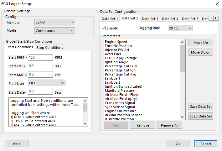
Data Set Configuration
There are 6 data sets that can hold 50 channels each.
Each data set has select-able “Logging Rate” so the user can manage what channels are being recorded at what speeds.